Embed Size (px)
Citation preview
Temposonics® Position Sensors for Industrial Applications
PRODUCT SELECTOR GUIDE

2 3
MEETING THE CHALLENGES OF INDUSTRIAL APPLICATIONSMetal Working • Wood Processing • Testing Machines • Drive Technology • Machine Tools Packaging & Printing Machineries • Paper & Glass Processing • Food & Beverage Plants Plastics & Rubber Processing • Textile Production • Renewable Energy • Power Generation
MTS Sensors also offers solutions for Mobile Hydraulics (off-highway vehicles) and Liquid Level applications
54
R-SERIES V - The new generation + TempoLink smart assistant 26 + 27Measurement Cycle
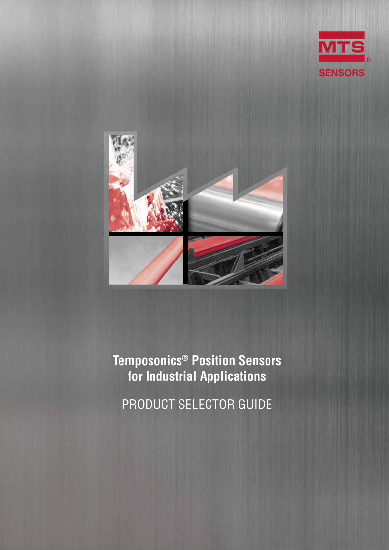
1 Current pulse generates magnetic field
2 Interaction with position magnet field generates torsional strain pulse
3 Torsional strain pulse propagates
4 Strain pulse detected by converter
5 Time-of-flight converted into position
Sensing element (Waveguide)
Position magnet (Magnetic field)
Torsional strain pulse converter
4
5
3
1
2
COMPANY & MEASURING TECHNOLOGY 5SENSORS SOLUTIONS AT A GLANCE 6
QUICK GUIDE & CERTIFICATES 16
TABLE OF CONTENTS
MEASURING TECHNOLOGYThe absolute, linear position sensors provided by MTS Sensors rely on the company’s proprietary Temposonics® magnetostrictive technology, which can determine position with a high level of precision and robustness. Each Temposonics® position sensor consists of a ferromagnetic wave-guide, a position magnet, a strain pulse converter and supporting electronics. The magnet, connected to the object in motion in the applica-tion, generates a magnetic field at its location on the waveguide. A short current pulse is applied to the waveguide. This creates a momentary radial magnetic field and torsional strain on the waveguide. The momentary interaction of the magnetic fields releases a torsional strain pulse that propagates the length of the waveguide. When the ultrasonic wave reaches the end of the waveguide it is converted into an electrical signal. Since the speed of the ultrasonic wave in the waveguide is precisely known, the time required to receive the return signal can be converted into a linear position measurement with both high accuracy and repeatability.
The Temposonics® technology, based on magnetostriction, does not rely on moving parts and is not exposed to mechanical stress. Therefore, the sensors exhibit considerably longer lifespans and much higher reliability when compared to other technologies, even in harsh working conditions. Furthermore, since the output from sensors with Temposonics® technol-ogy corresponds to an absolute position, rather than a relative value, it is not required to recalibrate sensors.
COMPANYMTS Sensors is recognized as an industry leader in sensing technolo-gies and solutions. These sensors permit high-precision and dynamic position and/or speed measurement in state-of-the-art automation and safety-relevant applications.
With a versatile and ever increasing product portfolio, MTS Sensors cooperates closely with customers, to optimize performance and reduce downtimes. Outstanding quality associated with practical know-how ensures that customers achieve utmost productivity and success. Continuous research, development and production of sensor systems constantly enable new solutions for measuring tasks in the industrial, mobile hydraulics as well as process technology fields to be created.
MTS Sensors is a division of MTS Systems Corporation (NASDAQ:MTSC). In July 2016, MTS Systems Corporation (Eden Prairie, USA) purchased PCB Piezotronics Inc. (Depew, USA). The acquisition will continue MTS’ and PCB’s long history of growth. Our customers benefit from an extended, complementary product portfolio, while relying on the unwavering competence and diligence of our support team. MTS Sensors has 1450 employees worldwide who serve our global customers with a focus on superior regional support.
E-SERIES - Compact solutions for limited spaces 20G-SERIES - High durability in harsh environments 22
GB-SERIES - Innovative design for demanding applications 24
R-SERIES - Superior performance solutions for challenging applications 28T-SERIES - Rugged design for hazardous environments 30
HAZARDOUS AREAS 32LOCAL SUPPORT 34
6 7
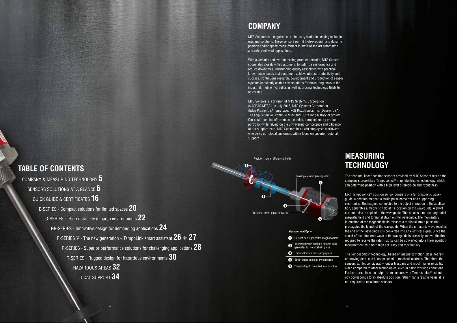
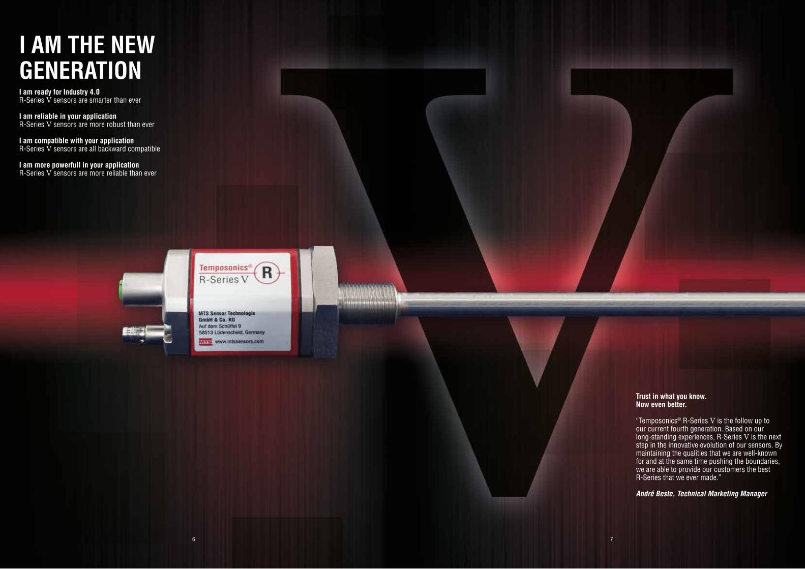
I AM THE NEWGENERATIONI am ready for Industry 4.0R-Series V sensors are smarter than ever
I am reliable in your applicationR-Series V sensors are more robust than ever
I am compatible with your applicationR-Series V sensors are all backward compatible
I am more powerfull in your applicationR-Series V sensors are more reliable than ever
Trust in what you know. Now even better.
“Temposonics® R-Series V is the follow up toour current fourth generation. Based on our long-standing experiences, R-Series V is the next step in the innovative evolution of our sensors. By maintaining the qualities that we are well-known for and at the same time pushing the boundaries, we are able to provide our customers the best R-Series that we ever made.”
André Beste, Technical Marketing Manager
8 9
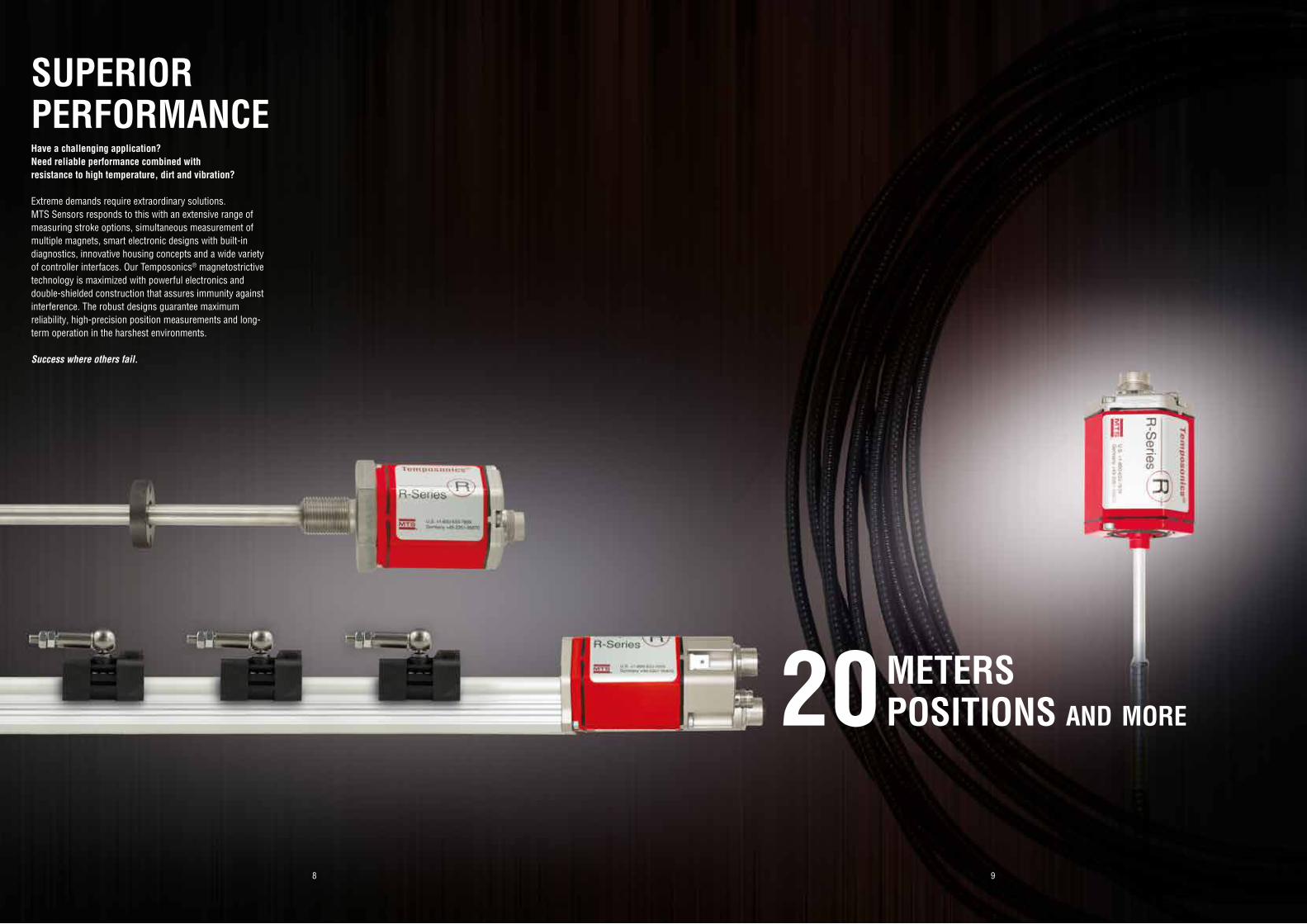
METERSPOSITIONS and more20
SUPERIORPERFORMANCEHave a challenging application? Need reliable performance combined with resistance to high temperature, dirt and vibration?
Extreme demands require extraordinary solutions. MTS Sensors responds to this with an extensive range of measuring stroke options, simultaneous measurement of multiple magnets, smart electronic designs with built-in diagnostics, innovative housing concepts and a wide variety of controller interfaces. Our Temposonics® magnetostrictive technology is maximized with powerful electronics and double-shielded construction that assures immunity against interference. The robust designs guarantee maximum reliability, high-precision position measurements and long-term operation in the harshest environments.
Success where others fail.
10 11
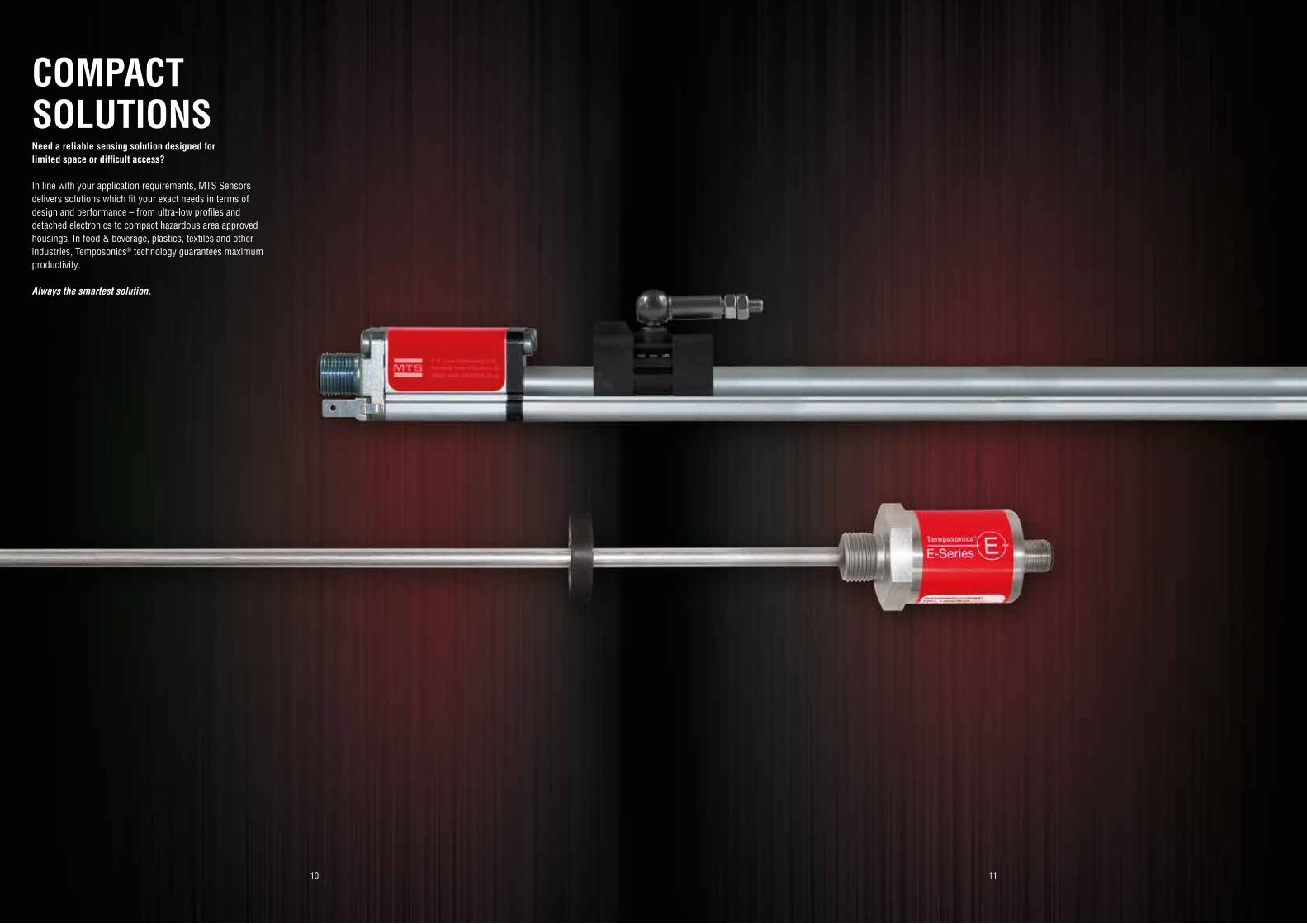
COMPACTSOLUTIONSNeed a reliable sensing solution designed for limited space or difficult access?
In line with your application requirements, MTS Sensors delivers solutions which fit your exact needs in terms of design and performance – from ultra-low profiles and detached electronics to compact hazardous area approved housings. In food & beverage, plastics, textiles and other industries, Temposonics® technology guarantees maximum productivity.
Always the smartest solution.
12 13
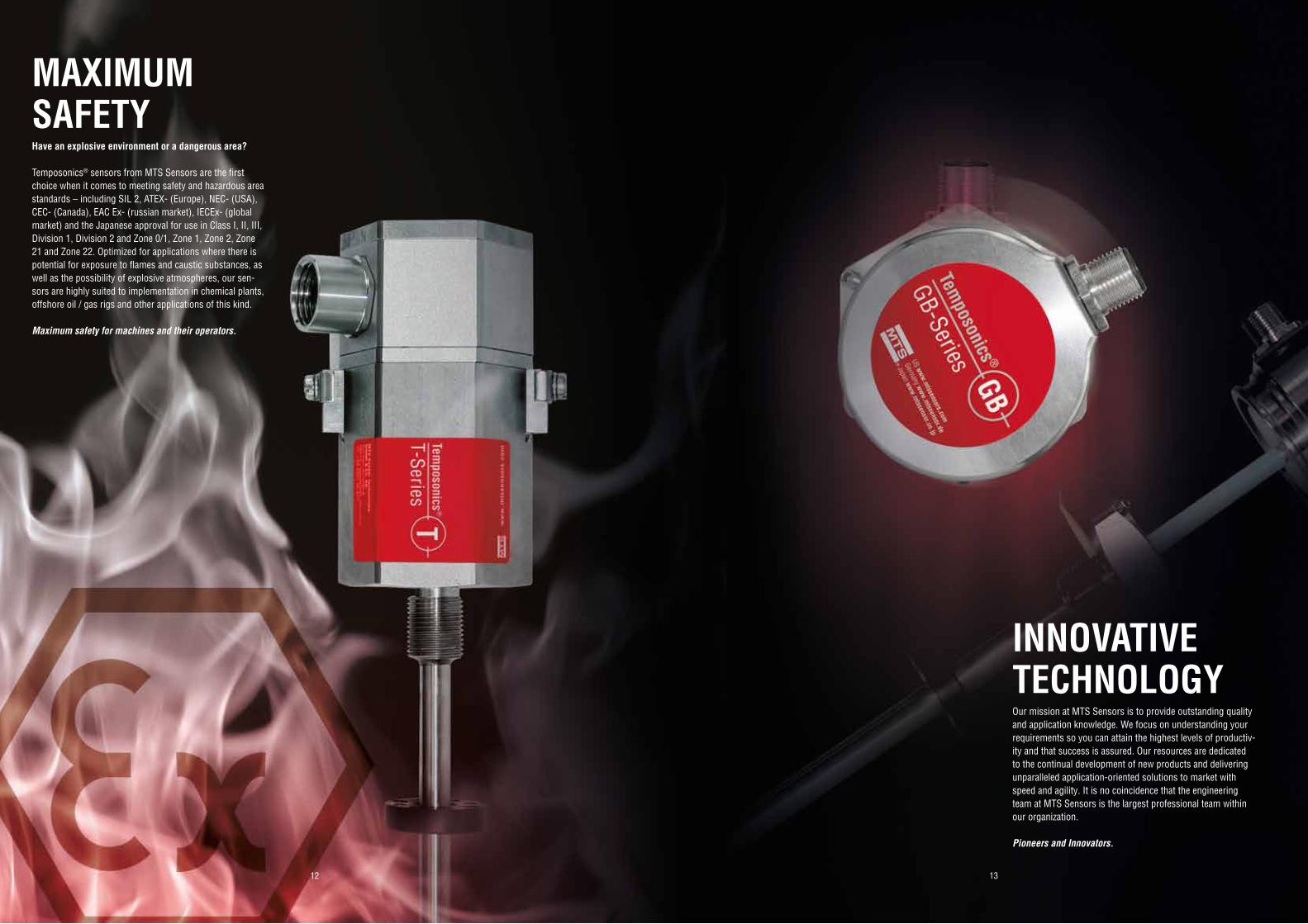
INNOVATIVETECHNOLOGYOur mission at MTS Sensors is to provide outstanding quality and application knowledge. We focus on understanding your requirements so you can attain the highest levels of productiv-ity and that success is assured. Our resources are dedicated to the continual development of new products and delivering unparalleled application-oriented solutions to market with speed and agility. It is no coincidence that the engineering team at MTS Sensors is the largest professional team within our organization.
Pioneers and Innovators.
MAXIMUMSAFETYHave an explosive environment or a dangerous area?
Temposonics® sensors from MTS Sensors are the first choice when it comes to meeting safety and hazardous area standards – including SIL 2, ATEX- (Europe), NEC- (USA), CEC- (Canada), EAC Ex- (russian market), IECEx- (global market) and the Japanese approval for use in Class I, II, III, Division 1, Division 2 and Zone 0/1, Zone 1, Zone 2, Zone 21 and Zone 22. Optimized for applications where there is potential for exposure to flames and caustic substances, as well as the possibility of explosive atmospheres, our sen-sors are highly suited to implementation in chemical plants, offshore oil / gas rigs and other applications of this kind.
Maximum safety for machines and their operators.
1514
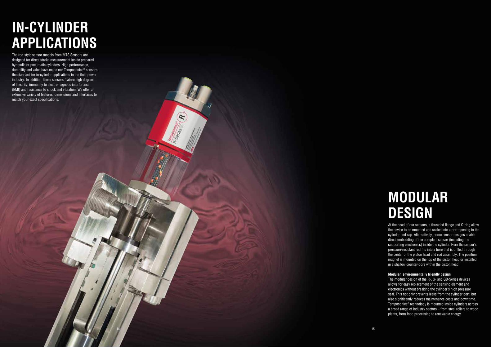
MODULARDESIGNAt the head of our sensors, a threaded flange and O-ring allow the device to be mounted and sealed into a port opening in the cylinder end cap. Alternatively, some sensor designs enable direct embedding of the complete sensor (including the supporting electronics) inside the cylinder. Here the sensor’s pressure-resistant rod fits into a bore that is drilled through the center of the piston head and rod assembly. The position magnet is mounted on the top of the piston head or installed in a shallow counter-bore within the piston head.
Modular, environmentally friendly designThe modular design of the R-, G- and GB-Series devices allows for easy replacement of the sensing element and electronics without breaking the cylinder‘s high pressure seal. This not only prevents leaks from the cylinder port, but also significantly reduces maintenance costs and downtime. Temposonics® technology is mounted inside cylinders across a broad range of industry sectors – from steel rollers to wood plants, from food processing to renewable energy.
IN-CYLINDER APPLICATIONSThe rod-style sensor models from MTS Sensors are designed for direct stroke measurement inside prepared hydraulic or pneumatic cylinders. High performance, durability and value have made our Temposonics® sensors the standard for in-cylinder applications in the fluid power industry. In addition, these sensors feature high degrees of linearity, immunity to electromagnetic interference (EMI) and resistance to shock and vibration. We offer an extensive variety of features, dimensions and interfaces to match your exact specifications.
16 17
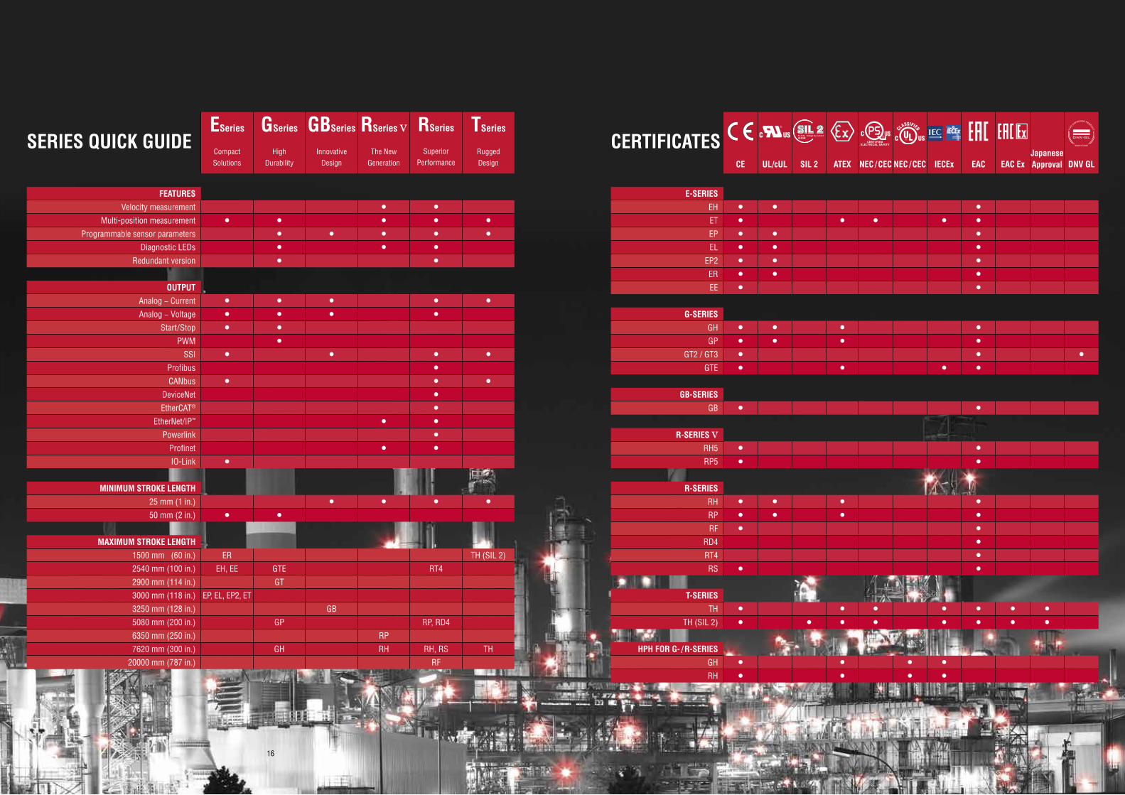
CERTIFICATES S a f e t y I n t e g r i t y L e v e lIEC 61508S a f e t y I n t e g r i t y L e v e lIEC 61508S a f e t y I n t e g r i t y L e v e lIEC 61508
JapaneseApprovalCE UL/cUL SIL 2 ATEX NEC / CEC NEC / CEC IECEx EAC EAC Ex DNV GL
E-SERIESEH • • •ET • • • • •EP • • •EL • • •
EP2 • • •ER • • •EE • •
G-SERIESGH • • • •GP • • • •
GT2 / GT3 • • •GTE • • • •
GB-SERIESGB • •
R-SERIES VRH5 • •RP5 • •
R-SERIESRH • • • •RP • • • •RF • •
RD4 •RT4 •RS • •
T-SERIESTH • • • • • • •
TH (SIL 2) • • • • • • • •
HPH FOR G- / R-SERIESGH • • • •RH • • • •
SERIES QUICK GUIDEESeries
Compact Solutions
GSeries
High Durability
GBSeries
Innovative Design
RSeries V
The New Generation
RSeries
Superior Performance
TSeries
Rugged Design
FEATURESVelocity measurement • •
Multi-position measurement • • • • •Programmable sensor parameters • • • • •
Diagnostic LEDs • • •Redundant version • •
OUTPUTAnalog − Current • • • • •Analog − Voltage • • • •
Start/Stop • •PWM •
SSI • • • •Profibus •CANbus • • •
DeviceNet •EtherCAT® •
EtherNet/IP™ • •Powerlink •
Profinet • •IO-Link •
MINIMUM STROKE LENGTH25 mm (1 in.) • • • •50 mm (2 in.) • •
MAXIMUM STROKE LENGTH 1500 mm (60 in.) ER TH (SIL 2)
2540 mm (100 in.) EH, EE GTE RT4
2900 mm (114 in.) GT
3000 mm (118 in.) EP, EL, EP2, ET
3250 mm (128 in.) GB
5080 mm (200 in.) GP RP, RD4
6350 mm (250 in.) RP
7620 mm (300 in.) GH RH RH, RS TH
20000 mm (787 in.) RF
18 19
100% FOR YOUQUALITY FROM HEAD TO TOE
2120
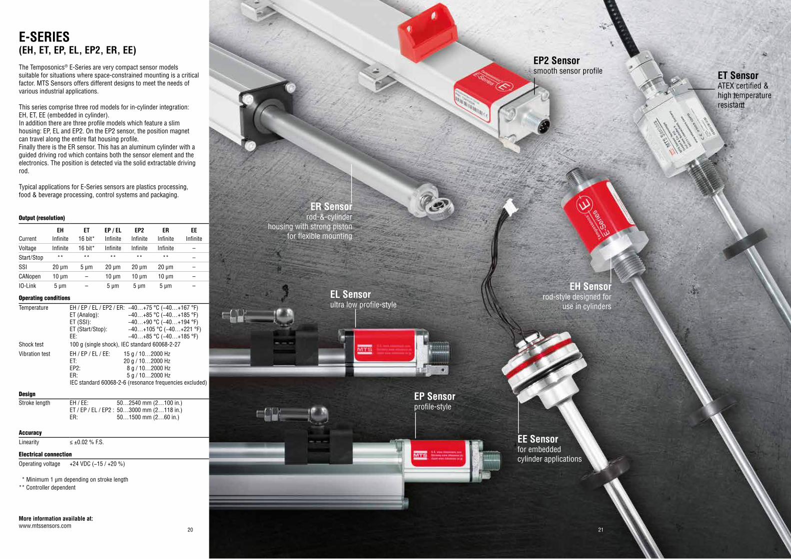
EH Sensorrod-style designed for
use in cylinders
ET SensorATEX certified &high temperature resistant
EP Sensorprofile-style
EE Sensorfor embedded cylinder applications
EP2 Sensorsmooth sensor profile
E-SERIES(EH, ET, EP, EL, EP2, ER, EE)The Temposonics® E-Series are very compact sensor models suitable for situations where space-constrained mounting is a critical factor. MTS Sensors offers different designs to meet the needs of various industrial applications.
This series comprise three rod models for in-cylinder integration: EH, ET, EE (embedded in cylinder).In addition there are three profile models which feature a slim housing: EP, EL and EP2. On the EP2 sensor, the position magnet can travel along the entire flat housing profile.Finally there is the ER sensor. This has an aluminum cylinder with a guided driving rod which contains both the sensor element and the electronics. The position is detected via the solid extractable driving rod.
Typical applications for E-Series sensors are plastics processing, food & beverage processing, control systems and packaging.
EL Sensorultra low profile-style
ER Sensorrod-&-cylinder
housing with strong piston for flexible mounting
Output (resolution)
Operating conditions
Temperature EH / EP / EL / EP2 / ER: −40…+75 °C (−40…+167 °F)ET (Analog): −40…+85 °C (−40…+185 °F)ET (SSI): −40…+90 °C (−40…+194 °F)ET (Start/Stop): −40…+105 °C (−40…+221 °F)EE: −40…+85 °C (−40…+185 °F)
Shock test 100 g (single shock), IEC standard 60068-2-27
Vibration test EH / EP / EL / EE: 15 g / 10…2000 HzET: 20 g / 10…2000 HzEP2: 8 g / 10…2000 Hz ER: 5 g / 10…2000 HzIEC standard 60068-2-6 (resonance frequencies excluded)
DesignStroke length EH / EE: 50…2540 mm (2…100 in.)
ET / EP / EL / EP2 : 50…3000 mm (2…118 in.)ER: 50…1500 mm (2…60 in.)
AccuracyLinearity ≤ ±0.02 % F.S.
Electrical connectionOperating voltage +24 VDC (−15 / +20 %)
EH ET EP / EL EP2 ER EECurrent Infinite 16 bit* Infinite Infinite Infinite Infinite
Voltage Infinite 16 bit* Infinite Infinite Infinite –
Start/Stop ** ** ** ** ** –
SSI 20 μm 5 μm 20 μm 20 μm 20 μm –
CANopen 10 µm – 10 µm 10 μm 10 μm –
IO-Link 5 µm – 5 µm 5 µm 5 µm –
* Minimum 1 µm depending on stroke length** Controller dependent
More information available at:www.mtssensors.com
2322
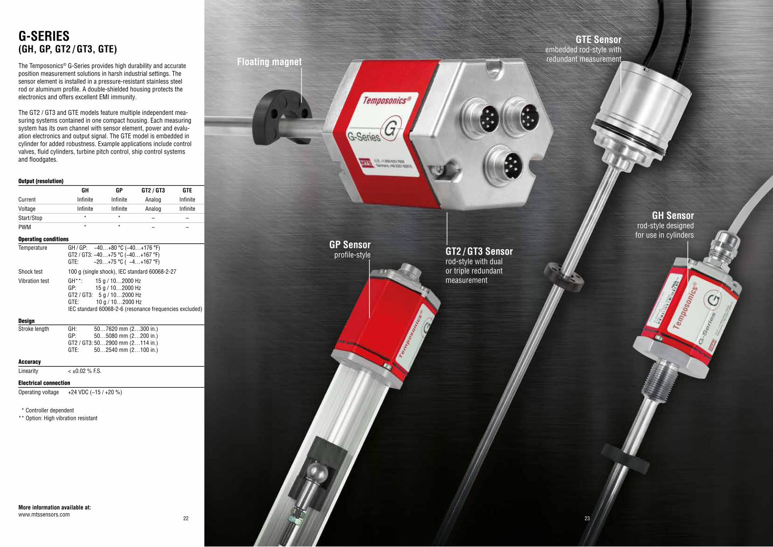
GH Sensorrod-style designed for use in cylinders
GT2 / GT3 Sensorrod-style with dual or triple redundantmeasurement
GTE Sensorembedded rod-style with redundant measurement
G-SERIES(GH, GP, GT2 / GT3, GTE)The Temposonics® G-Series provides high durability and accurate position measurement solutions in harsh industrial settings. The sensor element is installed in a pressure-resistant stainless steel rod or aluminum profile. A double-shielded housing protects the electronics and offers excellent EMI immunity.
The GT2 / GT3 and GTE models feature multiple independent mea-suring systems contained in one compact housing. Each measuring system has its own channel with sensor element, power and evalu-ation electronics and output signal. The GTE model is embedded in cylinder for added robustness. Example applications include control valves, fluid cylinders, turbine pitch control, ship control systems and floodgates.
Output (resolution)
Operating conditionsTemperature GH / GP: −40…+80 °C (−40…+176 °F)
GT2 / GT3: −40…+75 °C (−40…+167 °F)GTE: −20…+75 °C ( −4…+167 °F)
Shock test 100 g (single shock), IEC standard 60068-2-27
Vibration test GH**: 15 g / 10…2000 HzGP: 15 g / 10…2000 HzGT2 / GT3: 5 g / 10…2000 HzGTE: 10 g / 10…2000 HzIEC standard 60068-2-6 (resonance frequencies excluded)
DesignStroke length GH: 50…7620 mm (2…300 in.)
GP: 50…5080 mm (2…200 in.)GT2 / GT3: 50…2900 mm (2…114 in.)GTE: 50…2540 mm (2…100 in.)
AccuracyLinearity < ±0.02 % F.S.
Electrical connectionOperating voltage +24 VDC (−15 / +20 %)
GH GP GT2 / GT3 GTECurrent Infinite Infinite Analog Infinite
Voltage Infinite Infinite Analog Infinite
Start/Stop * * – –
PWM * * – –
GP Sensorprofile-style
Floating magnet
* Controller dependent** Option: High vibration resistant
More information available at:www.mtssensors.com
2524
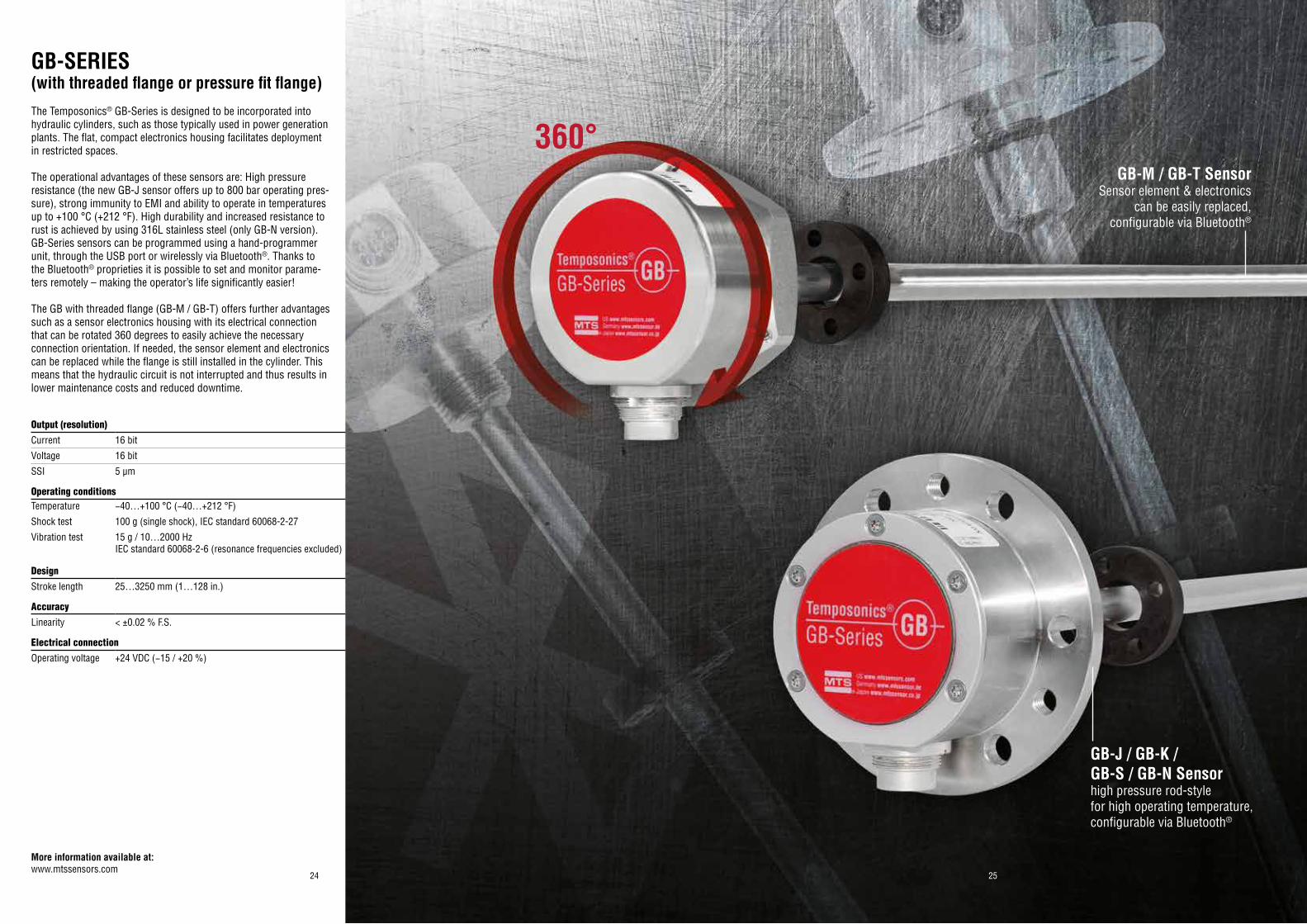
GB-J / GB-K / GB-S / GB-N Sensorhigh pressure rod-stylefor high operating temperature, configurable via Bluetooth®
GB-M / GB-T SensorSensor element & electronics
can be easily replaced, configurable via Bluetooth®
GB-SERIES(with threaded flange or pressure fit flange)The Temposonics® GB-Series is designed to be incorporated into hydraulic cylinders, such as those typically used in power generation plants. The flat, compact electronics housing facilitates deployment in restricted spaces.
The operational advantages of these sensors are: High pressure resistance (the new GB-J sensor offers up to 800 bar operating pres-sure), strong immunity to EMI and ability to operate in temperatures up to +100 °C (+212 °F). High durability and increased resistance to rust is achieved by using 316L stainless steel (only GB-N version).GB-Series sensors can be programmed using a hand-programmer unit, through the USB port or wirelessly via Bluetooth®. Thanks to the Bluetooth® proprieties it is possible to set and monitor parame-ters remotely – making the operator’s life significantly easier!
The GB with threaded flange (GB-M / GB-T) offers further advantages such as a sensor electronics housing with its electrical connection that can be rotated 360 degrees to easily achieve the necessary connection orientation. If needed, the sensor element and electronics can be replaced while the flange is still installed in the cylinder. This means that the hydraulic circuit is not interrupted and thus results in lower maintenance costs and reduced downtime.
Output (resolution)Current 16 bit
Voltage 16 bit
SSI 5 µm
Operating conditionsTemperature −40…+100 °C (−40…+212 °F)
Shock test 100 g (single shock), IEC standard 60068-2-27
Vibration test 15 g / 10…2000 Hz IEC standard 60068-2-6 (resonance frequencies excluded)
DesignStroke length 25…3250 mm (1…128 in.)
AccuracyLinearity < ±0.02 % F.S.
Electrical connectionOperating voltage +24 VDC (−15 / +20 %)
360°
More information available at:www.mtssensors.com
26 27
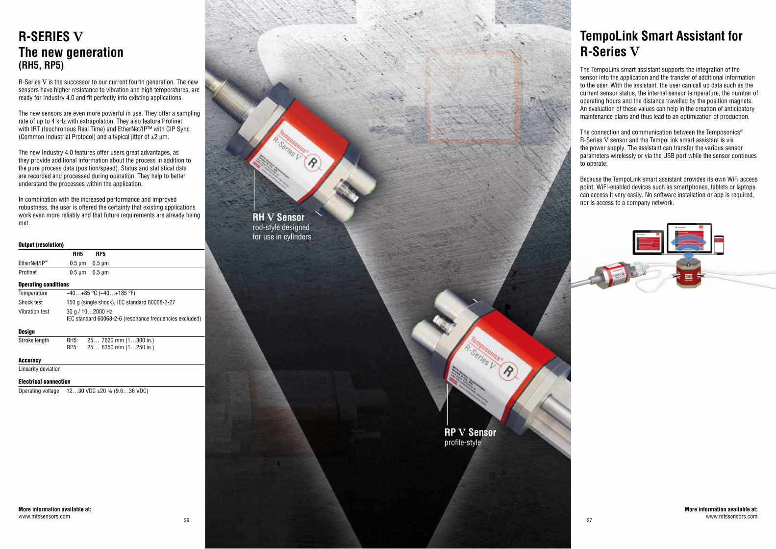
R-SERIES VThe new generation(RH5, RP5)R-Series V is the successor to our current fourth generation. The new sensors have higher resistance to vibration and high temperatures, are ready for Industry 4.0 and fit perfectly into existing applications. The new sensors are even more powerful in use. They offer a sampling rate of up to 4 kHz with extrapolation. They also feature Profinet with IRT (Isochronous Real Time) and EtherNet/IP™ with CIP Sync (Common Industrial Protocol) and a typical jitter of ±2 µm. The new Industry 4.0 features offer users great advantages, as they provide additional information about the process in addition to the pure process data (position/speed). Status and statistical data are recorded and processed during operation. They help to better understand the processes within the application. In combination with the increased performance and improved robustness, the user is offered the certainty that existing applications work even more reliably and that future requirements are already being met.
Output (resolution)
Operating conditionsTemperature −40…+85 °C (−40…+185 °F)
Shock test 150 g (single shock), IEC standard 60068-2-27
Vibration test 30 g / 10…2000 HzIEC standard 60068-2-6 (resonance frequencies excluded)
DesignStroke length RH5: 25… 7620 mm (1…300 in.)
RP5: 25… 6350 mm (1…250 in.)
AccuracyLinearity deviation
Electrical connectionOperating voltage 12…30 VDC ±20 % (9.6…36 VDC)
RH5 RP5EtherNet/IP™ 0.5 µm 0.5 µm
Profinet 0.5 µm 0.5 µm
TempoLink Smart Assistant for R-Series VThe TempoLink smart assistant supports the integration of the sensor into the application and the transfer of additional information to the user. With the assistant, the user can call up data such as the current sensor status, the internal sensor temperature, the number of operating hours and the distance travelled by the position magnets. An evaluation of these values can help in the creation of anticipatory maintenance plans and thus lead to an optimization of production. The connection and communication between the Temposonics® R-Series V sensor and the TempoLink smart assistant is via the power supply. The assistant can transfer the various sensor parameters wirelessly or via the USB port while the sensor continues to operate. Because the TempoLink smart assistant provides its own WiFi access point, WiFI-enabled devices such as smartphones, tablets or laptops can access it very easily. No software installation or app is required, nor is access to a company network.
RH V Sensorrod-style designed for use in cylinders
RP V Sensorprofile-style
More information available at:www.mtssensors.com
More information available at:www.mtssensors.com
*Option: High vibration resistant
2928
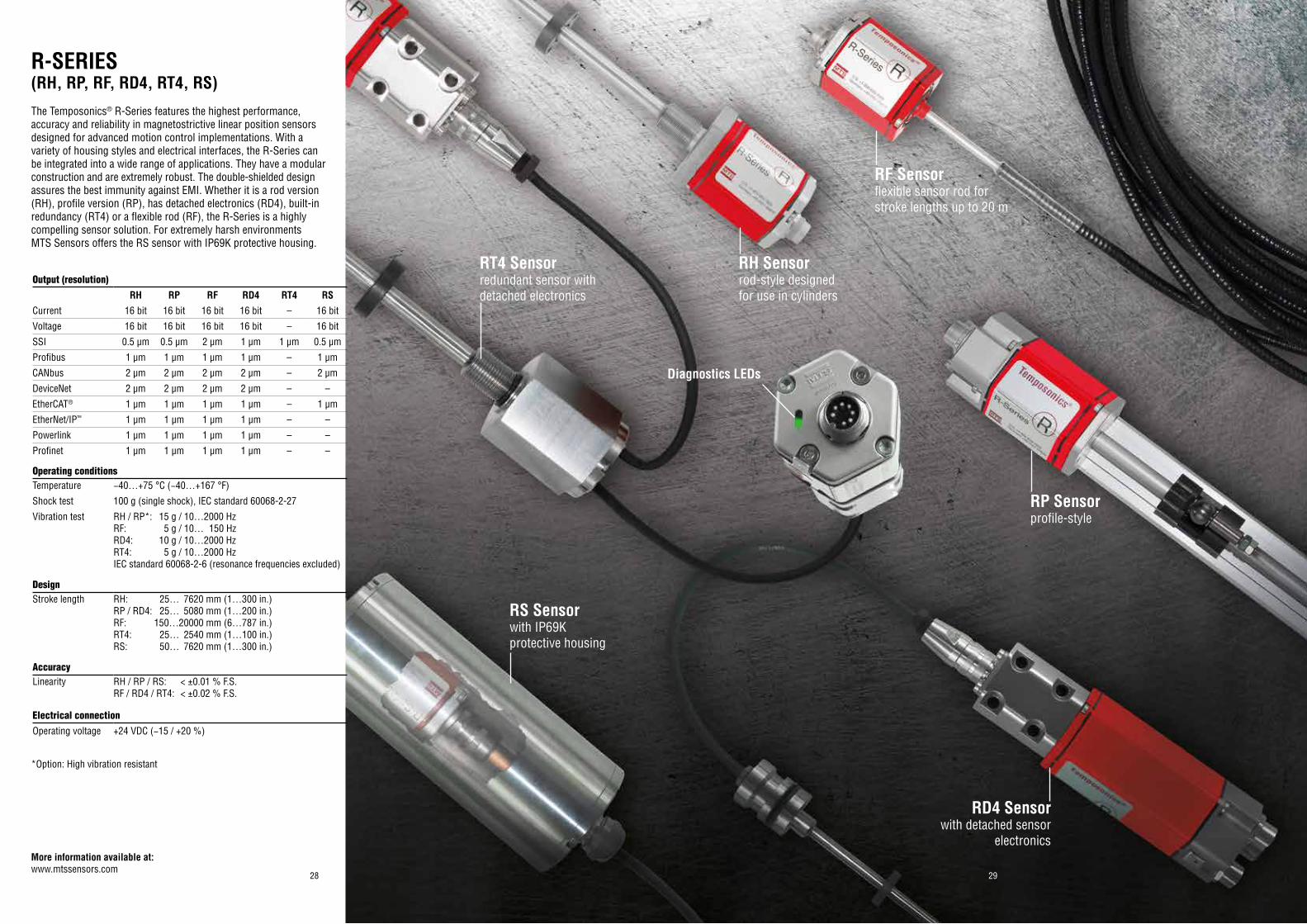
R-SERIES(RH, RP, RF, RD4, RT4, RS)The Temposonics® R-Series features the highest performance, accuracy and reliability in magnetostrictive linear position sensors designed for advanced motion control implementations. With a variety of housing styles and electrical interfaces, the R-Series can be integrated into a wide range of applications. They have a modular construction and are extremely robust. The double-shielded design assures the best immunity against EMI. Whether it is a rod version (RH), profile version (RP), has detached electronics (RD4), built-in redundancy (RT4) or a flexible rod (RF), the R-Series is a highly compelling sensor solution. For extremely harsh environments MTS Sensors offers the RS sensor with IP69K protective housing.
Output (resolution)
Operating conditionsTemperature −40…+75 °C (−40…+167 °F)
Shock test 100 g (single shock), IEC standard 60068-2-27
Vibration test RH / RP*: 15 g / 10…2000 HzRF: 5 g / 10… 150 HzRD4: 10 g / 10…2000 HzRT4: 5 g / 10…2000 HzIEC standard 60068-2-6 (resonance frequencies excluded)
DesignStroke length RH: 25… 7620 mm (1…300 in.)
RP / RD4: 25… 5080 mm (1…200 in.)RF: 150…20000 mm (6…787 in.)RT4: 25… 2540 mm (1…100 in.) RS: 50… 7620 mm (1…300 in.)
AccuracyLinearity RH / RP / RS: < ±0.01 % F.S.
RF / RD4 / RT4: < ±0.02 % F.S.
Electrical connectionOperating voltage +24 VDC (−15 / +20 %)
RH RP RF RD4 RT4 RSCurrent 16 bit 16 bit 16 bit 16 bit – 16 bit
Voltage 16 bit 16 bit 16 bit 16 bit – 16 bit
SSI 0.5 µm 0.5 µm 2 µm 1 µm 1 µm 0.5 µm
Profibus 1 µm 1 µm 1 µm 1 µm – 1 µm
CANbus 2 µm 2 µm 2 µm 2 µm – 2 µm
DeviceNet 2 µm 2 µm 2 µm 2 µm – –
EtherCAT® 1 µm 1 µm 1 µm 1 µm – 1 µm
EtherNet/IP™ 1 µm 1 µm 1 µm 1 µm – –
Powerlink 1 µm 1 µm 1 µm 1 µm – –
Profinet 1 µm 1 µm 1 µm 1 µm – –
RH Sensorrod-style designed for use in cylinders
RP Sensorprofile-style
RF Sensorflexible sensor rod for stroke lengths up to 20 m
RD4 Sensorwith detached sensor
electronics
RS Sensorwith IP69K protective housing
RT4 Sensorredundant sensor with detached electronics
More information available at:www.mtssensors.com
Diagnostics LEDs
3130
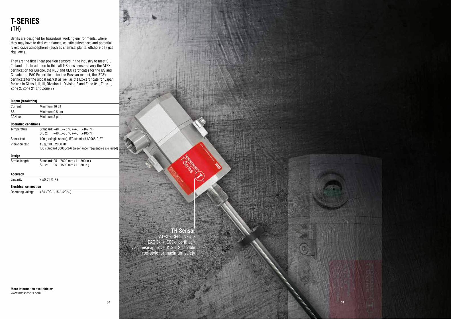
T-SERIES(TH)Series are designed for hazardous working environments, where they may have to deal with flames, caustic substances and potential-ly explosive atmospheres (such as chemical plants, offshore oil / gas rigs, etc.).
They are the first linear position sensors in the industry to meet SIL 2 standards. In addition to this, all T-Series sensors carry the ATEX certification for Europe, the NEC and CEC certificates for the US and Canada, the EAC Ex certificate for the Russian market, the IECEx certificate for the global market as well as the Ex-certificate for Japan for use in Class I, II, III, Division 1, Division 2 and Zone 0/1, Zone 1, Zone 2, Zone 21 and Zone 22.
Output (resolution)Current Minimum 16 bit
SSI Minimum 0.5 µmCANbus Minimum 2 µm
Operating conditionsTemperature Standard: −40…+75 °C (−40…+167 °F)
SIL 2: −40…+85 °C (−40…+185 °F)
Shock test 100 g (single shock), IEC standard 60068-2-27
Vibration test 15 g / 10…2000 Hz IEC standard 60068-2-6 (resonance frequencies excluded)
Design Stroke length Standard: 25…7620 mm (1…300 in.)
SIL 2: 25…1500 mm (1…60 in.)
AccuracyLinearity < ±0.01 % F.S.
Electrical connectionOperating voltage +24 VDC (−15 / +20 %)
TH SensorATEX-/ CEC- /NEC- /
EAC Ex / IECEx- certified /Japanese approval & SIL 2 capable
rod-style for maximum safety
More information available at:www.mtssensors.com
3332
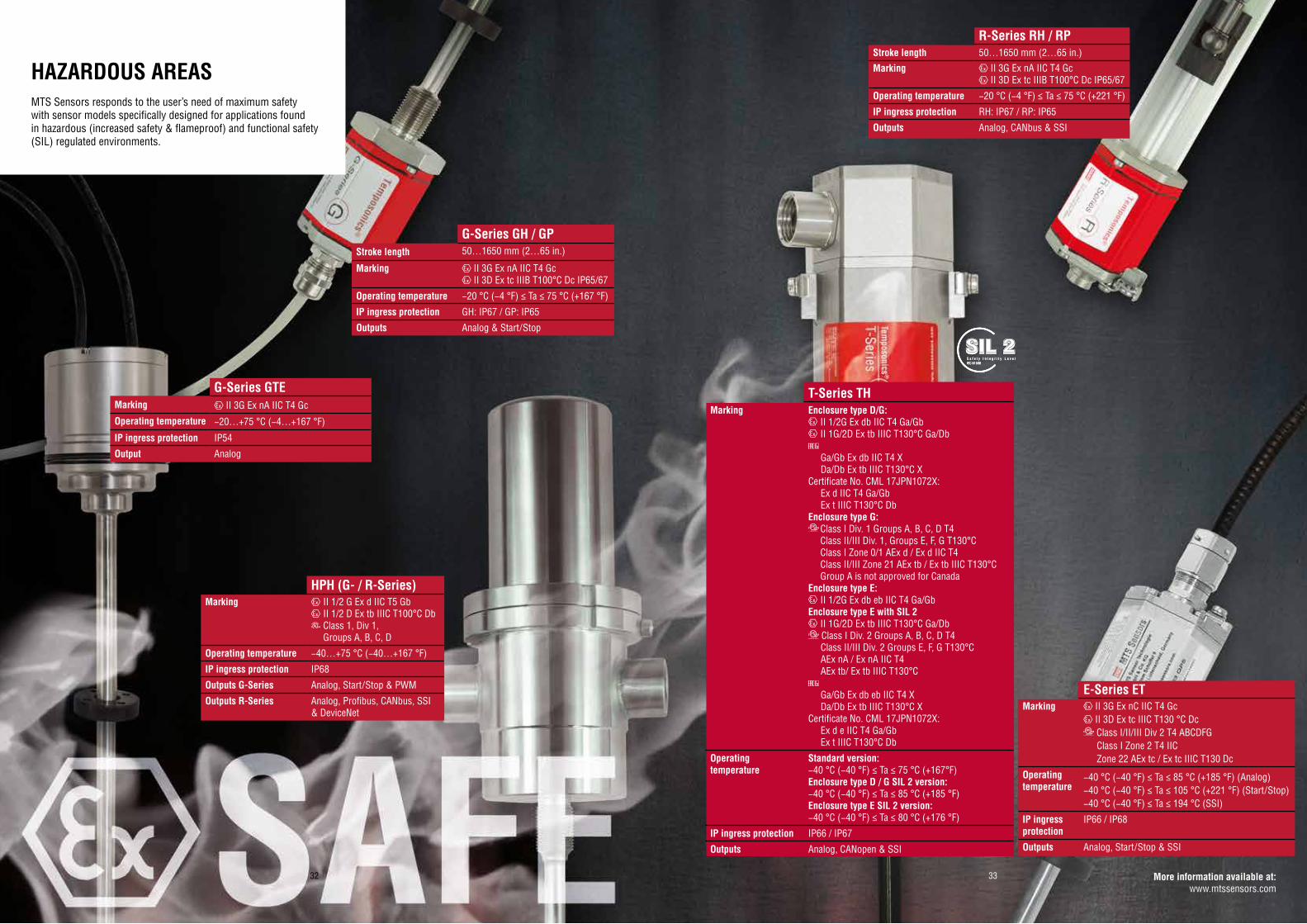
T-Series THMarking Enclosure type D/G:
II 1/2G Ex db IIC T4 Ga/Gb II 1G/2D Ex tb IIIC T130°C Ga/Db
Ga/Gb Ex db IIC T4 X Da/Db Ex tb IIIC T130°C XCertificate No. CML 17JPN1072X: Ex d IIC T4 Ga/Gb Ex t IIIC T130°C DbEnclosure type G:
Class I Div. 1 Groups A, B, C, D T4 Class II/III Div. 1, Groups E, F, G T130°C Class I Zone 0/1 AEx d / Ex d IIC T4 Class II/III Zone 21 AEx tb / Ex tb IIIC T130°C Group A is not approved for CanadaEnclosure type E:
II 1/2G Ex db eb IIC T4 Ga/GbEnclosure type E with SIL 2
II 1G/2D Ex tb IIIC T130°C Ga/Db Class I Div. 2 Groups A, B, C, D T4
Class II/III Div. 2 Groups E, F, G T130°C AEx nA / Ex nA IIC T4 AEx tb/ Ex tb IIIC T130°C
Ga/Gb Ex db eb IIC T4 X Da/Db Ex tb IIIC T130°C XCertificate No. CML 17JPN1072X: Ex d e IIC T4 Ga/Gb Ex t IIIC T130°C Db
Operating temperature
Standard version:−40 °C (−40 °F) ≤ Ta ≤ 75 °C (+167°F)Enclosure type D / G SIL 2 version:−40 °C (−40 °F) ≤ Ta ≤ 85 °C (+185 °F)Enclosure type E SIL 2 version:−40 °C (−40 °F) ≤ Ta ≤ 80 °C (+176 °F)
IP ingress protection IP66 / IP67
Outputs Analog, CANopen & SSI
E-Series ETMarking II 3G Ex nC IIC T4 Gc
II 3D Ex tc IIIC T130 °C Dc Class I/II/III Div 2 T4 ABCDFG
Class I Zone 2 T4 IIC Zone 22 AEx tc / Ex tc IIIC T130 Dc
Operating temperature
−40 °C (−40 °F) ≤ Ta ≤ 85 °C (+185 °F) (Analog)−40 °C (−40 °F) ≤ Ta ≤ 105 °C (+221 °F) (Start/Stop)−40 °C (−40 °F) ≤ Ta ≤ 194 °C (SSI)
IP ingress protection
IP66 / IP68
Outputs Analog, Start/Stop & SSI
G-Series GH / GPStroke length 50…1650 mm (2…65 in.)
Marking II 3G Ex nA IIC T4 Gc II 3D Ex tc IIIB T100°C Dc IP65/67
Operating temperature −20 °C (−4 °F) ≤ Ta ≤ 75 °C (+167 °F)
IP ingress protection GH: IP67 / GP: IP65
Outputs Analog & Start/Stop
G-Series GTEMarking II 3G Ex nA IIC T4 Gc
Operating temperature −20…+75 °C (−4…+167 °F)
IP ingress protection IP54
Output Analog
HPH (G- / R-Series)Marking II 1/2 G Ex d IIC T5 Gb
II 1/2 D Ex tb IIIC T100°C Db Class 1, Div 1,
Groups A, B, C, D
Operating temperature −40…+75 °C (−40…+167 °F)
IP ingress protection IP68
Outputs G-Series Analog, Start/Stop & PWM
Outputs R-Series Analog, Profibus, CANbus, SSI & DeviceNet
R-Series RH / RPStroke length 50…1650 mm (2…65 in.)
Marking II 3G Ex nA IIC T4 Gc II 3D Ex tc IIIB T100°C Dc IP65/67
Operating temperature −20 °C (−4 °F) ≤ Ta ≤ 75 °C (+221 °F)
IP ingress protection RH: IP67 / RP: IP65
Outputs Analog, CANbus & SSI
HAZARDOUS AREASMTS Sensors responds to the user’s need of maximum safety with sensor models specifically designed for applications found in hazardous (increased safety & flameproof) and functional safety (SIL) regulated environments.
More information available at:www.mtssensors.com
S a f e t y I n t e g r i t y L e v e lIEC 61508S a f e t y I n t e g r i t y L e v e lIEC 61508S a f e t y I n t e g r i t y L e v e lIEC 61508
34 35
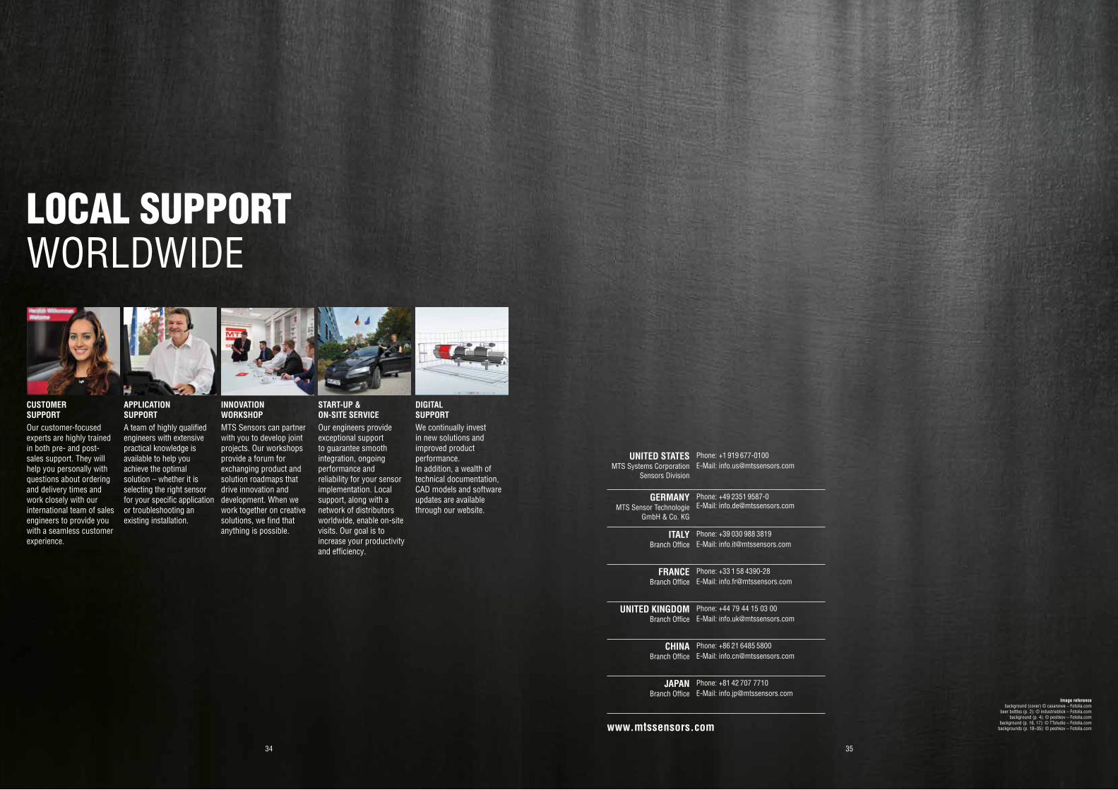
CUSTOMERSUPPORT
APPLICATION SUPPORT
INNOVATIONWORKSHOP
START-UP & ON-SITE SERVICE
DIGITAL SUPPORT
Our customer-focused experts are highly trained in both pre- and post-sales support. They will help you personally with questions about ordering and delivery times and work closely with our international team of sales engineers to provide you with a seamless customer experience.
A team of highly qualified engineers with extensive practical knowledge is available to help you achieve the optimal solution – whether it is selecting the right sensor for your specific application or troubleshooting an existing installation.
MTS Sensors can partner with you to develop joint projects. Our workshops provide a forum for exchanging product and solution roadmaps that drive innovation and development. When we work together on creative solutions, we find that anything is possible.
Our engineers provide exceptional support to guarantee smooth integration, ongoing performance and reliability for your sensor implementation. Local support, along with a network of distributors worldwide, enable on-site visits. Our goal is to increase your productivity and efficiency.
We continually invest in new solutions and improved product performance. In addition, a wealth of technical documentation, CAD models and software updates are available through our website.
LOCAL SUPPORTWORLDWIDE
www.mtssensors.com
Image referencebackground (cover) © casanowe – Fotolia.com
beer bottles (p. 2): © industrieblick – Fotolia.combackground (p. 4): © peshkov – Fotolia.com
background (p. 16, 17): © TTstudio – Fotolia.combackgrounds (p. 18–35): © peshkov – Fotolia.com
UNITED STATESMTS Systems Corporation
Sensors Division
Phone: +1 919 677-0100E-Mail: [email protected]
GERMANYMTS Sensor Technologie
GmbH & Co. KG
Phone: +49 2351 9587-0E-Mail: [email protected]
ITALYBranch Office
Phone: +39 030 988 3819E-Mail: [email protected]
FRANCEBranch Office
Phone: +33 1 58 4390-28E-Mail: [email protected]
UNITED KINGDOMBranch Office
Phone: +44 79 44 15 03 00E-Mail: [email protected]
CHINABranch Office
Phone: +86 21 6485 5800 E-Mail: [email protected]
JAPANBranch Office
Phone: +81 42 707 7710E-Mail: [email protected]

Document Part Number: 551814 Revision D (EN) 03/2018
MTS, Temposonics and Level Plus are registered trademarks of MTS Systems Corporation in the United States; MTS SENSORS and the MTS SENSORS logo are trademarks of MTS Systems Corporation within the United States. These trademarks may be protected in other countries. All other trademarks are the property of their respective owners. Copyright © 2018 MTS Systems Corporation. No license of any intellectual property rights is granted. MTS reserves the right to change the information within this document, change product designs, or withdraw products from availability for purchase without notice. Typographic and graphics errors or omissions are unintentional and subject to correction. Visit www.mtssensors.com for the latest product information.
LEGA
L NO
TICE
S