Embed Size (px)
Citation preview
The Influence of Lumbar Spine Posture on the Neck Range of Motion and the Change in Lumbar Spine Posture during Frontal Impact – A Volunteer Study
Internship at Chalmers University Sweden
Joris Geurts MT05.29
Thesis partner: Marcus Bergqvist Institute: Technische Universiteit Eindhoven Faculteit: Werktuigbouwkunde Afstudeerrichting: AES – Vehicle Safety Student nummer: 461672 Supervisor Chalmers: Mats Svensson Supervisor TU/e: Hans van Dommelen Göteborg, Sweden, June 1st 2005 Crash Safety Division Department of Machine and Vehicle Systems Chalmers University of Technology
Abstract Neck injuries in traffic accidents are not uncommon, and the cost of rehabilitation and loss of productivity connected is a major problem for society. Although a number of hypotheses about injury mechanisms are defined, there are still a lot of uncertainties regarding the occurrence of whiplash injuries, mostly depending on the high amount of complexity of the human spine. This thesis consist of two volunteer studies; A static study aimed at investigating the influence of lumbar spine posture on the neck range of motion, and a dynamic study aimed at finding a description of the change in lumbar spine posture during frontal impacts. The work in the static study is based on the hypothesis that the end of the range of motion of the neck is critical for the occurrence of whiplash injuries. The study is performed with a car seat containing a modified lumbar support. For different degrees of positive and negative lumbar support, the volunteers’ head movements in protraction, retraction, flexion and extension are measured and analysed. The results from the study are difficult to interpret, mainly because of the large influence of human error during the performance and recurrence of the movements. However, the results indicate that a large amount of lumbar support, i.e. increasing lordosis, corresponds to an increasing range of motion for the extension movement and a decreasing ability of flexion movement. The opposite results are found for the case of no lumbar support at all, i.e. a slouched seated position. In the dynamic study, a low speed frontal impact sled is used, where the volunteers experience a frontal impact at approximately 7 km/h. The movement of the volunteers’ lumbar spine is measured and analysed using tracking software and accelerometer transducers. The result of this pilot study is a description of the change in lumbar spine posture during the impact. The results are varying, however, mostly due to the differences of the anatomy of the volunteers’ spines. The resulting outcome of these two studies is showing discrepancies and appears to be difficult to draw unambiguous conclusions from. However, this is expected when working with human volunteers. The anatomy, pain threshold level, and level of commitment all differs between each individual volunteer. These differences are to be viewed upon together with the fact that most of the measurements are done with film markers attached to the skin, whose movements are recorded by cameras and examined by tracking software. Thus, it is evident that this leads to an error in the measurements that in some cases could be larger than the measured change in movement for the different parameters. This makes drawing solid conclusions a difficult task.
II
Contents
ABSTRACT ................................................................................................................................................. II
LIST OF ABBREVIATIONS AND TERMS .............................................................................................V
1 INTRODUCTION ................................................................................................................................. 1
1.1 FACTS AND FIGURES.............................................................................................................................. 1 1.2 THE HUMAN SPINE ................................................................................................................................. 2 1.3 THE PELVIS............................................................................................................................................ 3 1.4 SYMPTOMS, INJURY SITES AND MECHANISMS [1, 5, 7, 12, 15, 16].......................................................... 3 1.5 GOAL..................................................................................................................................................... 6 1.5.1 STATIC STUDY ...................................................................................................................................... 6 1.5.2 DYNAMIC STUDY .................................................................................................................................. 6
2 TEST SET-UP STATIC STUDY: THE LUMBAR SUPPORT TEST.............................................. 7
2.1 DESCRIPTION OF THE TEST..................................................................................................................... 7 2.2 MODIFIED LUMBAR SUPPORT DESIGN .................................................................................................... 7 2.3 SEAT SET-UP.......................................................................................................................................... 8 2.4 VOLUNTEER SET-UP............................................................................................................................... 8 2.4.1 INSTRUCTIONS TO THE VOLUNTEERS ..................................................................................................... 9 2.4.2 VOLUNTEER DATA................................................................................................................................ 9 2.5 THE EXECUTION OF THE TEST .............................................................................................................. 10 2.6 CONDITIONS AND ASSUMPTIONS IN THE STUDY ................................................................................... 10
3 ANALYSIS AND RESULTS STATIC STUDY ................................................................................ 12
3.1 TEMA TRACKEYE® ........................................................................................................................... 12 3.2 RESULTS.............................................................................................................................................. 12 3.3 DISCUSSION OF THE RESULTS .............................................................................................................. 15
4 TEST SET-UP DYNAMIC STUDY: LOW SPEED FRONTAL IMPACT ................................... 16
4.1 DESCRIPTION OF THE TEST................................................................................................................... 16 4.2 THE SLED AND SEAT DESIGN................................................................................................................ 16 4.3 THE SLED SET-UP................................................................................................................................. 17 4.4 VOLUNTEER SET-UP............................................................................................................................. 17 4.4.1 INSTRUCTIONS TO THE VOLUNTEERS ................................................................................................... 18 4.4.2 VOLUNTEER DATA.............................................................................................................................. 18 4.5 THE EXECUTION OF THE TEST .............................................................................................................. 19 4.6 CONDITIONS AND ASSUMPTIONS.......................................................................................................... 19
5 ANALYSIS AND RESULTS DYNAMIC STUDY ........................................................................... 20
5.1 TEMA TRACKEYE® ........................................................................................................................... 20 5.2 RESULTS.............................................................................................................................................. 20 5.3 DISCUSSION OF THE RESULTS .............................................................................................................. 22
III
6 GENERAL DISCUSSION .................................................................................................................. 24
7 CONCLUSIONS.................................................................................................................................. 26
REFERENCES ........................................................................................................................................... 27
APPENDIX A DEPTH SCALING ERROR CALCULATION [21] ..................................................... 30
APPENDIX B DISTORTION TEST ....................................................................................................... 31
APPENDIX C MEASUREMENT ERROR TEMA TRACKEYE® ..................................................... 32
APPENDIX D DATA SHEETS STATIC STUDY.................................................................................. 33
APPENDIX E COMBINED RESULTS STATIC STUDY .................................................................... 48
APPENDIX F EVALUATION PERFORMANCE ERROR STATIC STUDY ................................... 50
APPENDIX G RESULTS DYNAMIC STUDY: LUMBAR SPINE MARKERS ................................ 51
APPENDIX H RESULTS DYNAMIC STUDY: ACCELEROMETER DATA................................... 55
IV
List of abbreviations and terms AIS Abbreviated Injury Scale ASIC Anterior Superior Iliac Crest Atlas C1, 1st cervical vertebra Axis C2, 2nd cervical vertebra C1 – C7 The cervical vertebrae Extension Rearward bending of the neck Flexion Forward bending of the neck G Acceleration of gravity (1G = 9,81 m/s2) Kyphosis Outward curve of the spine L1 – L7 The lumbar vertebrae Lordosis Inward curve of the spine Protraction Forward horizontal displacement of the head relative to the torso,
causing flexion of the lower part of the neck and extension of the upper part of the neck
Retraction Rearward horizontal displacement of the head relative to the torso, causing extension of the lower part of the neck and flexion of the upper part of the neck
Rebound Phase where the body is coming back in the opposite direction of the impact
SAE Society of Automotive Engineers T1 – T12 Thoracic vertebrae WAD Whiplash associated disorders µ Mean σ Standard deviation of a population
V
1 Introduction
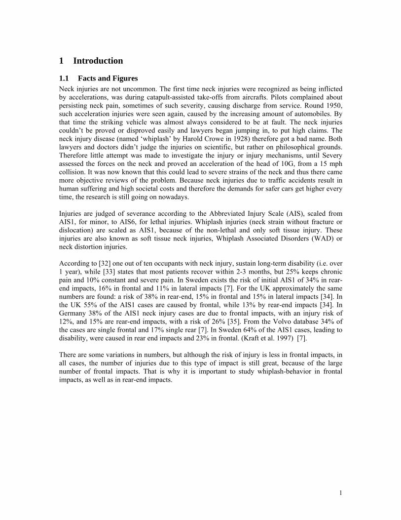
1.1 Facts and Figures Neck injuries are not uncommon. The first time neck injuries were recognized as being inflicted by accelerations, was during catapult-assisted take-offs from aircrafts. Pilots complained about persisting neck pain, sometimes of such severity, causing discharge from service. Round 1950, such acceleration injuries were seen again, caused by the increasing amount of automobiles. By that time the striking vehicle was almost always considered to be at fault. The neck injuries couldn’t be proved or disproved easily and lawyers began jumping in, to put high claims. The neck injury disease (named ‘whiplash’ by Harold Crowe in 1928) therefore got a bad name. Both lawyers and doctors didn’t judge the injuries on scientific, but rather on philosophical grounds. Therefore little attempt was made to investigate the injury or injury mechanisms, until Severy assessed the forces on the neck and proved an acceleration of the head of 10G, from a 15 mph collision. It was now known that this could lead to severe strains of the neck and thus there came more objective reviews of the problem. Because neck injuries due to traffic accidents result in human suffering and high societal costs and therefore the demands for safer cars get higher every time, the research is still going on nowadays. Injuries are judged of severance according to the Abbreviated Injury Scale (AIS), scaled from AIS1, for minor, to AIS6, for lethal injuries. Whiplash injuries (neck strain without fracture or dislocation) are scaled as AIS1, because of the non-lethal and only soft tissue injury. These injuries are also known as soft tissue neck injuries, Whiplash Associated Disorders (WAD) or neck distortion injuries. According to [32] one out of ten occupants with neck injury, sustain long-term disability (i.e. over 1 year), while [33] states that most patients recover within 2-3 months, but 25% keeps chronic pain and 10% constant and severe pain. In Sweden exists the risk of initial AIS1 of 34% in rear-end impacts, 16% in frontal and 11% in lateral impacts [7]. For the UK approximately the same numbers are found: a risk of 38% in rear-end, 15% in frontal and 15% in lateral impacts [34]. In the UK 55% of the AIS1 cases are caused by frontal, while 13% by rear-end impacts [34]. In Germany 38% of the AIS1 neck injury cases are due to frontal impacts, with an injury risk of 12%, and 15% are rear-end impacts, with a risk of 26% [35]. From the Volvo database 34% of the cases are single frontal and 17% single rear [7]. In Sweden 64% of the AIS1 cases, leading to disability, were caused in rear end impacts and 23% in frontal. (Kraft et al. 1997) [7]. There are some variations in numbers, but although the risk of injury is less in frontal impacts, in all cases, the number of injuries due to this type of impact is still great, because of the large number of frontal impacts. That is why it is important to study whiplash-behavior in frontal impacts, as well as in rear-end impacts.
1
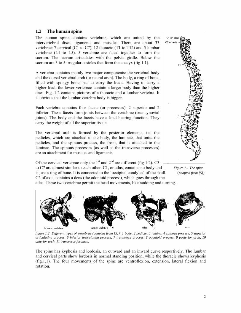
1.2 The human spine The human spine contains vertebrae, which are united by the intervertebral discs, ligaments and muscles. There are about 33 vertebrae: 7 cervical (C1 to C7), 12 thoracic (T1 to T12) and 5 lumbar vertebrae (L1 to L5). 5 vertebrae are fused together to form the sacrum. The sacrum articulates with the pelvic girdle. Below the sacrum are 3 to 5 irregular ossicles that form the coccyx (fig 1.1). A vertebra contains mainly two major components: the vertebral body and the dorsal vertebral arch (or neural arch). The body, a ring of bone, filled with spongy bone, has to carry the loads. Having to carry a higher load, the lower vertebrae contain a larger body than the higher ones. Fig. 1.2 contains pictures of a thoracic and a lumbar vertebra. It is obvious that the lumbar vertebra body is bigger. Each vertebra contains four facets (or processes), 2 superior and 2 inferior. These facets form joints between the vertebrae (true synovial joints). The body and the facets have a load bearing function. They carry the weight of all the superior tissue. The vertebral arch is formed by the posterior elements, i.e. the pedicles, which are attached to the body, the laminae, that unite the pedicles, and the spinous process, the front, that is attached to the laminae. The spinous processes (as well as the transverse processes) are an attachment for muscles and ligaments. Of the cervical vertebrae only the 1st and 2nd are different (fig 1.2). C3 to C7 are almost similar to each other. C1, or atlas, contains no body and Figure 1.1 The spine is just a ring of bone. It is connected to the ‘occipital condyles’ of the skull. (adapted from [5]) C2 of axis, contains a dens (the odontoid process), which goes through the atlas. These two vertebrae permit the head movements, like nodding and turning.
figure 1.2 Different types of vertebrae (adapted from [5]): 1 body, 2 pedicle, 3 lamina, 4 spinous process, 5 superior articulating process, 6 inferior articulating process, 7 transverse process, 8 odontoid process, 9 posterior arch, 10 anterior arch, 11 transverse foramen. The spine has kyphosis and lordosis, an outward and an inward curve respectively. The lumbar and cervical parts show lordosis in normal standing position, while the thoracic shows kyphosis (fig.1.1). The four movements of the spine are ventroflexion, extension, lateral flexion and rotation.
2
1.3 The pelvis The pelvis orientation largely determines the curvature of the lower back, i.e. a more upright rotated pelvis gives more lordosis in the lumbar spine. For defining the pelvic rotation normally a reference plane is used, that appears as a straight line when the pelvis is viewed laterally [5]. The plane is formed by the two ASIC’s (anterior-superior iliac crest, the anchor-points for the belt, that prevent submarining) and pubic symphysis. Standing the angle of this plane with the vertical is around 0 degrees; seated it is about 41 degrees. Because of this rearward rotation flexion of the lumbar spine will occur.
Figure 1.3 The pelvis (adapted from [26]) The ASIC is easy to mark, but the pubic symphysis is hard to find on volunteers, because of soft tissue and privacy reasons. Therefore other reference points can be chosen instead. Possible points are the H-point, (i.e. the hip joint), the trochanter, or the D-point [25], also known as the ischial tuberosity, the lowest point of the pelvis, the bone that carries most of the weight in sitting position. D-point however is also difficult to mark, because it is situated ‘in the seat’.
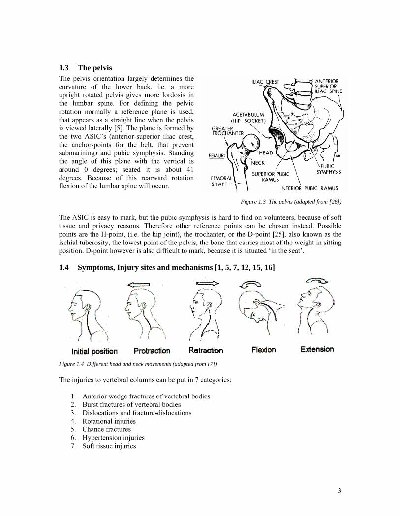
1.4 Symptoms, Injury sites and mechanisms [1, 5, 7, 12, 15, 16]
Figure 1.4 Different head and neck movements (adapted from [7]) The injuries to vertebral columns can be put in 7 categories:
1. Anterior wedge fractures of vertebral bodies 2. Burst fractures of vertebral bodies 3. Dislocations and fracture-dislocations 4. Rotational injuries 5. Chance fractures 6. Hypertension injuries 7. Soft tissue injuries
3
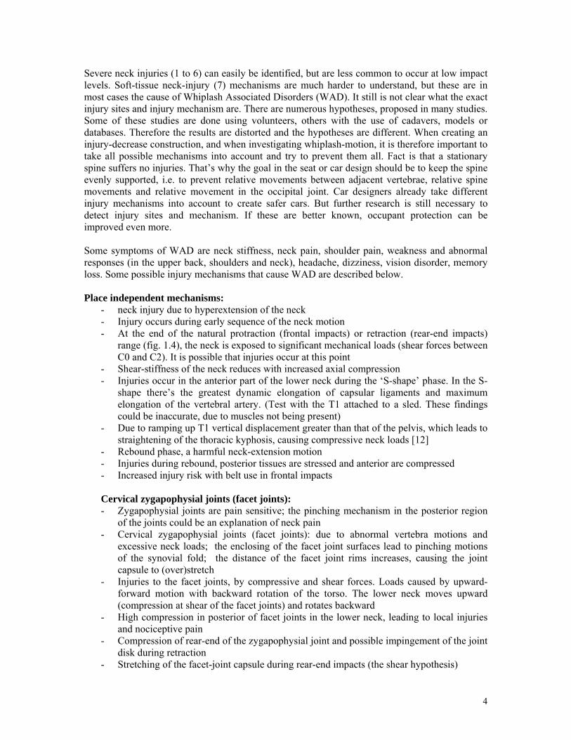
Severe neck injuries (1 to 6) can easily be identified, but are less common to occur at low impact levels. Soft-tissue neck-injury (7) mechanisms are much harder to understand, but these are in most cases the cause of Whiplash Associated Disorders (WAD). It still is not clear what the exact injury sites and injury mechanism are. There are numerous hypotheses, proposed in many studies. Some of these studies are done using volunteers, others with the use of cadavers, models or databases. Therefore the results are distorted and the hypotheses are different. When creating an injury-decrease construction, and when investigating whiplash-motion, it is therefore important to take all possible mechanisms into account and try to prevent them all. Fact is that a stationary spine suffers no injuries. That’s why the goal in the seat or car design should be to keep the spine evenly supported, i.e. to prevent relative movements between adjacent vertebrae, relative spine movements and relative movement in the occipital joint. Car designers already take different injury mechanisms into account to create safer cars. But further research is still necessary to detect injury sites and mechanism. If these are better known, occupant protection can be improved even more. Some symptoms of WAD are neck stiffness, neck pain, shoulder pain, weakness and abnormal responses (in the upper back, shoulders and neck), headache, dizziness, vision disorder, memory loss. Some possible injury mechanisms that cause WAD are described below. Place independent mechanisms:
- neck injury due to hyperextension of the neck - Injury occurs during early sequence of the neck motion - At the end of the natural protraction (frontal impacts) or retraction (rear-end impacts)
range (fig. 1.4), the neck is exposed to significant mechanical loads (shear forces between C0 and C2). It is possible that injuries occur at this point
- Shear-stiffness of the neck reduces with increased axial compression - Injuries occur in the anterior part of the lower neck during the ‘S-shape’ phase. In the S-
shape there’s the greatest dynamic elongation of capsular ligaments and maximum elongation of the vertebral artery. (Test with the T1 attached to a sled. These findings could be inaccurate, due to muscles not being present)
- Due to ramping up T1 vertical displacement greater than that of the pelvis, which leads to straightening of the thoracic kyphosis, causing compressive neck loads [12]
- Rebound phase, a harmful neck-extension motion - Injuries during rebound, posterior tissues are stressed and anterior are compressed - Increased injury risk with belt use in frontal impacts Cervical zygapophysial joints (facet joints): - Zygapophysial joints are pain sensitive; the pinching mechanism in the posterior region
of the joints could be an explanation of neck pain - Cervical zygapophysial joints (facet joints): due to abnormal vertebra motions and
excessive neck loads; the enclosing of the facet joint surfaces lead to pinching motions of the synovial fold; the distance of the facet joint rims increases, causing the joint capsule to (over)stretch
- Injuries to the facet joints, by compressive and shear forces. Loads caused by upward-forward motion with backward rotation of the torso. The lower neck moves upward (compression at shear of the facet joints) and rotates backward
- High compression in posterior of facet joints in the lower neck, leading to local injuries and nociceptive pain
- Compression of rear-end of the zygapophysial joint and possible impingement of the joint disk during retraction
- Stretching of the facet-joint capsule during rear-end impacts (the shear hypothesis)
4
Cervical intervertebral discs:
- Cervical intervertebral discs: avulsion of the disc from vertrebral-end plate and tears of the disk
- Intervertebral disc injury due to excessive neck loads and local hyperextension/flexion, causing (over)stretch
Ligaments:
- Alar ligaments - Ligamentum flavum spanning adjacent vertebra on the inside of the vertebral canal - Capsular ligament surrounding joints between articular processes (facet or zygapophysial
joints) - Ligament, local hyperextension/flexion , causing (over)stretch
Muscles:
- Cervical muscles, due to rapid contraction in response to impact - Deep muscles injury, due to local hyperextension/flexion, causing (over)stretch. - Injury to the sterno cleidomastoid muscle, caused by contraction, leading to stretch.
Neural structures:
- Neural structures are affected by increased tensile forces, possibly induced by flexion in the upper neck. This leads to a neuropathic pain process.
- Cervical nervous system injuries (e.g. the posterior nerve root ganglion), due to pressure pulses in the spinal canal
- Brain, brainstem and cord, due to local hyperextension/flexion and pressure pulses in the spinal canal
Lumbar spine injuries The symptoms of lumbar spine injuries are low back pain and pain radiating down to extremities. The mechanisms that could cause injuries in the lumbar spine are the same as for cervical injuries. Ergonomics [14, 23] Drivers have a higher risk to develop an acute hernital lumbar inter vertebra disc than people that do not drive. This could be caused by the higher pressure within the intervertebral discs for sitting posture, with respect to standing posture. This higher pressure is caused by the decrease in lordosis. The extension of the knees (normal for car-seated-posture), lead to a pull in the hamstring muscles, which will lead to a rotation of the pelvis, causing the lumbar spine to flatten. To maintain lordosis of the lumbar spine, a lumbar support can be added. In 1974 a study shows that using a lumbar support (with a maximum of 50 mm) could reduce the intradiscal pressure. Another study however stated that the support was comfortable if it didn’t exceeded 20 mm. Although the intradiscal pressure in higher, the pull of the hamstring was lower. So for comfort there has to be a compromise.
5
1.5 Goal For this thesis two studies are done. They will be described separately and named ‘static study’ and ‘dynamic study’.
1.5.1 Static study The goal of this study is to investigate the influence of the lumbar spine and pelvis posture on the neck range of motion. This question primarily relates to neck injury risk (whiplash) and neck protection. A test rig including a car seat will be modified to allow controlled lumbar posture adjustment and neck mobility measurements in human volunteers. The results are expected to give new insight into how the requirements on head-support should be related to the lumbar support design as well as how the lumbar posture influences the whiplash injury potential in frontal impacts. The work is based on the hypothesis that the end of the range of retraction-, protraction-, flexion- and extension-motion of the neck is critical for the occurrence of whiplash injuries.
1.5.2 Dynamic study In this study the goal is to find a description of the change in lumbar spine posture during frontal impacts. This is a pilot study, so that in a future study human volunteers and dummies can be compared at lower impact speed, for improvement of the spine behavior of a dummy. The study will include the development of a test set-up as well as some pilot testing and analysis. The results are expected to be of importance for both whiplash- and lumbar spine injuries in frontal impacts.
6
2 Test set-up static study: The lumbar support test
2.1 Description of the test The aim of the lumbar support test is to evaluate the influence of the lumbar spine curvature on the neck range of motion. The demand on the test set-up is to allow a great variance in the lumbar support range. An ordinary lumbar support in a car seat has an adjusting range of about 25-40 mm between its least and most supportive positions. The objective with the modified lumbar support is to have the possibility of attaining maximum lordosis for all of the volunteers, something that can not be done with the original lumbar support. Furthermore, the modified lumbar support has to be able to offer a completely slouched seated position for any volunteer person. A completely slouched position means that the volunteer should be able to let his back sink into the seat without anything obstructing it, leading to a slumped posture, i.e. a flexed spine. The car seat used in the study is a Volvo P2X front seat, production year 2004. This seat model is used in the Volvo S60 and V70 range from year model 2000. The expected result outcome of the tests is data of movement for protraction, retraction, flexion, and extension of the neck for different seated lumbar postures. Protraction is the forward horizontal motion of the head, without tilting it. Retraction is the corresponding rearward horizontal motion. Flexion is the forward bending of the neck (i.e. put the chin against the chest), and extension is the rearward bending of the neck (i.e. look into the roof). Figure 1.4 in Chapter 1 illustrates the different positions. The knee angle of the volunteers will also be altered between a normal driving posture, with the feet at the pedals, and one posture with the feet on the floor, i.e. less knee angle, giving less stretched hamstring muscles. Earlier results (Kelsey and Hardy) have showed that the amount of stretch on the hamstring muscles, i.e. the knee angle, has influence on the ability to achieve an inward curve of the lower part of the back. In this study, skin markers and a still camera are used because of their simplicity and cost efficiency. These types of film targets, attached to the skin with sports tape are accurate enough for this type of study. [27]
2.2 Modified lumbar support design The definition of a lumbar support is: a structure that contacts the lower back around the lumbar spine, with the purpose to bring the spine closer to the standing posture, and thus to improve comfort and postural stability. The demand on the lumbar support design is that it should follow the lumbar lordosis; it should not be to flat, nor too deep. The support should start at a height of the L4 or L5 vertebra, i.e. at or below the top of the pelvis [23]. This gives the position of the lumbar support apex to around the L3 vertebrae. To enable for the large range in lumbar support, the original support together with upholstery, foam, and parts of the supportive metal grid is removed from the seat back. In the place of the original lumbar support a heavily modified support is mounted. This support has a capability of offering a maximum lumbar support of up to 135 mm relative to the neutral position of the original lumbar support, defined as the medium position of the adjustable lumbar support on the reference seat. The way of movement is perpendicular to the seat back frame. The support can also be altered in height, 40 mm downwards and the same amount upwards, to suit most of the volunteers’ preferences according to [23]. The moving part of the support consists of two side panels with position holes, connected by a curved plate which forms the contact surface with the volunteers’ back. The height position of the apex of the curved plate in its intermediate position coincides with the location of the original lumbar support. There are 14 available positions in the
7
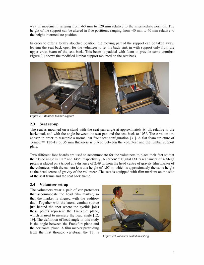
way of movement, ranging from -60 mm to 120 mm relative to the intermediate position. The height of the support can be altered in five positions, ranging from -40 mm to 40 mm relative to the height intermediate position. In order to offer a totally slouched position, the moving part of the support can be taken away, leaving the seat back open for the volunteer to let his back sink in with support only from the upper cross beam of the seat back. This beam is padded with foam to provide some comfort. Figure 2.1 shows the modified lumbar support mounted on the seat back.
Figure 2.1 Modified lumbar support.
2.3 Seat set-up The seat is mounted on a stand with the seat pan angle at approximately 6° tilt relative to the horizontal, and with the angle between the seat pan and the seat back to 103°. These values are chosen in order to resemble a normal car front seat configuration [31]. A flat foam structure of Tempur™ T85-18 of 35 mm thickness is placed between the volunteer and the lumbar support plate. Two different foot boards are used to accommodate for the volunteers to place their feet so that their knee angle is 100° and 145°, respectively. A Canon™ Digital IXUS 40 camera of 4 Mega pixels is placed on a tripod at a distance of 2.49 m from the head centre of gravity film marker of the volunteer, with the camera lens at a height of 1.05 m, which is approximately the same height as the head centre of gravity of the volunteer. The seat is equipped with film markers on the side of the seat frame and the seat back frame.
2.4 Volunteer set-up The volunteers wear a pair of ear protectors that accommodate the head film marker, so that the marker is aligned with the auditory duct. Together with the lateral canthus (tissue just behind the spot where the eyelids join) these points represent the Frankfurt plane, which is used to measure the head angle [12, 19]. The definition of head angle in this study is the angle between the Frankfurt plane and the horizontal plane. A film marker protruding from the first thoracic vertebrae, the T1, is Figure 2.3 Volunteer seated in test rig
8
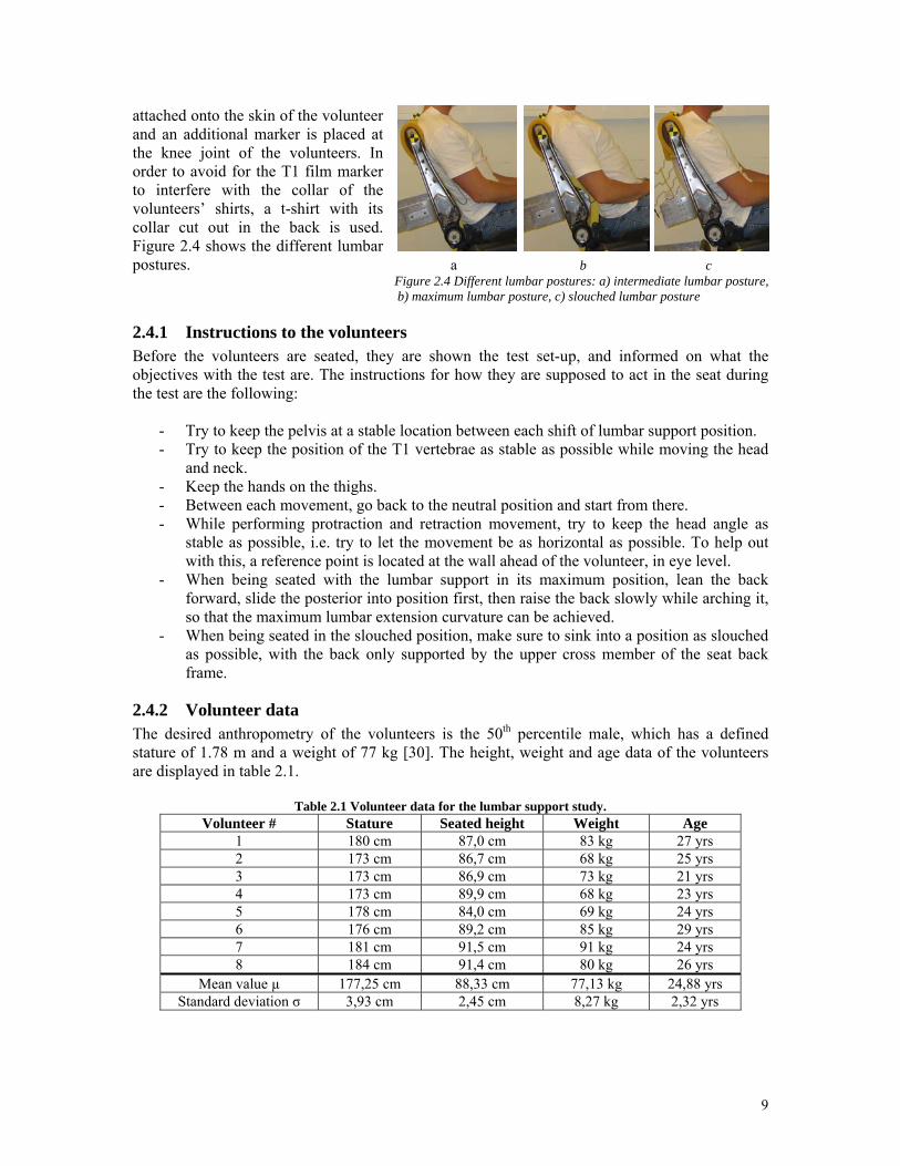
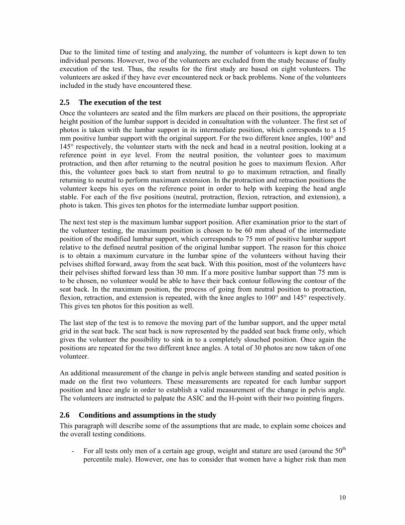
attached onto the skin of the volunteer and an additional marker is placed at the knee joint of the volunteers. In order to avoid for the T1 film marker to interfere with the collar of the volunteers’ shirts, a t-shirt with its collar cut out in the back is used. Figure 2.4 shows the different lumbar postures. a b c
Figure 2.4 Different lumbar postures: a) intermediate lumbar posture, b) maximum lumbar posture, c) slouched lumbar posture
2.4.1 Instructions to the volunteers Before the volunteers are seated, they are shown the test set-up, and informed on what the objectives with the test are. The instructions for how they are supposed to act in the seat during the test are the following:
- Try to keep the pelvis at a stable location between each shift of lumbar support position. - Try to keep the position of the T1 vertebrae as stable as possible while moving the head
and neck. - Keep the hands on the thighs. - Between each movement, go back to the neutral position and start from there. - While performing protraction and retraction movement, try to keep the head angle as
stable as possible, i.e. try to let the movement be as horizontal as possible. To help out with this, a reference point is located at the wall ahead of the volunteer, in eye level.
- When being seated with the lumbar support in its maximum position, lean the back forward, slide the posterior into position first, then raise the back slowly while arching it, so that the maximum lumbar extension curvature can be achieved.
- When being seated in the slouched position, make sure to sink into a position as slouched as possible, with the back only supported by the upper cross member of the seat back frame.
2.4.2 Volunteer data The desired anthropometry of the volunteers is the 50th percentile male, which has a defined stature of 1.78 m and a weight of 77 kg [30]. The height, weight and age data of the volunteers are displayed in table 2.1.
Table 2.1 Volunteer data for the lumbar support study. Volunteer # Stature Seated height Weight Age
1 180 cm 87,0 cm 83 kg 27 yrs 2 173 cm 86,7 cm 68 kg 25 yrs 3 173 cm 86,9 cm 73 kg 21 yrs 4 173 cm 89,9 cm 68 kg 23 yrs 5 178 cm 84,0 cm 69 kg 24 yrs 6 176 cm 89,2 cm 85 kg 29 yrs 7 181 cm 91,5 cm 91 kg 24 yrs 8 184 cm 91,4 cm 80 kg 26 yrs
Mean value µ 177,25 cm 88,33 cm 77,13 kg 24,88 yrs Standard deviation σ 3,93 cm 2,45 cm 8,27 kg 2,32 yrs
9
Due to the limited time of testing and analyzing, the number of volunteers is kept down to ten individual persons. However, two of the volunteers are excluded from the study because of faulty execution of the test. Thus, the results for the first study are based on eight volunteers. The volunteers are asked if they have ever encountered neck or back problems. None of the volunteers included in the study have encountered these.
2.5 The execution of the test Once the volunteers are seated and the film markers are placed on their positions, the appropriate height position of the lumbar support is decided in consultation with the volunteer. The first set of photos is taken with the lumbar support in its intermediate position, which corresponds to a 15 mm positive lumbar support with the original support. For the two different knee angles, 100° and 145° respectively, the volunteer starts with the neck and head in a neutral position, looking at a reference point in eye level. From the neutral position, the volunteer goes to maximum protraction, and then after returning to the neutral position he goes to maximum flexion. After this, the volunteer goes back to start from neutral to go to maximum retraction, and finally returning to neutral to perform maximum extension. In the protraction and retraction positions the volunteer keeps his eyes on the reference point in order to help with keeping the head angle stable. For each of the five positions (neutral, protraction, flexion, retraction, and extension), a photo is taken. This gives ten photos for the intermediate lumbar support position. The next test step is the maximum lumbar support position. After examination prior to the start of the volunteer testing, the maximum position is chosen to be 60 mm ahead of the intermediate position of the modified lumbar support, which corresponds to 75 mm of positive lumbar support relative to the defined neutral position of the original lumbar support. The reason for this choice is to obtain a maximum curvature in the lumbar spine of the volunteers without having their pelvises shifted forward, away from the seat back. With this position, most of the volunteers have their pelvises shifted forward less than 30 mm. If a more positive lumbar support than 75 mm is to be chosen, no volunteer would be able to have their back contour following the contour of the seat back. In the maximum position, the process of going from neutral position to protraction, flexion, retraction, and extension is repeated, with the knee angles to 100° and 145° respectively. This gives ten photos for this position as well. The last step of the test is to remove the moving part of the lumbar support, and the upper metal grid in the seat back. The seat back is now represented by the padded seat back frame only, which gives the volunteer the possibility to sink in to a completely slouched position. Once again the positions are repeated for the two different knee angles. A total of 30 photos are now taken of one volunteer. An additional measurement of the change in pelvis angle between standing and seated position is made on the first two volunteers. These measurements are repeated for each lumbar support position and knee angle in order to establish a valid measurement of the change in pelvis angle. The volunteers are instructed to palpate the ASIC and the H-point with their two pointing fingers.
2.6 Conditions and assumptions in the study This paragraph will describe some of the assumptions that are made, to explain some choices and the overall testing conditions.
- For all tests only men of a certain age group, weight and stature are used (around the 50th percentile male). However, one has to consider that women have a higher risk than men
10
to suffer WAD. Also a thinner neck results in a higher risk, and the risk varies with age weight and stature [7, 19]. Therefore the results may vary when other groups are tested.
- The tests are done during the day. Some volunteers are tested in the morning, while others are tested in the afternoon. It is assumed that this does not influence the behavior of the volunteers.
- Assumed is that WAD occurs at the end of the natural range of head motion. Therefore four positions are evaluated and tested in the static test, i.e. protraction, flexion, retraction and extension. When the range is greater it is probable that the risk of WAD is smaller.
- For this test comfort and ergonomics are not considered. E.g. the maximum lumbar support as used in the static test leads to an uncomfortable seating position and will never be used in a real car.
- More lumbar support leads to a greater pressure and a larger compression of the foam. This leads to slightly less increase of support than prescribed.
- Especially the arms are not in a real driving position. This could influence the neck and spine behavior.
All these conditions and assumption may cause slightly different results, than those that would be found in a real crash situation.
11
3 Analysis and results static study
3.1 TEMA TrackEye® For the analysis of the photographs, as described in chapter 2, the software TEMA TrackEye®, version 2.3, is used. Points are added on the position of the centres of the film markers. 2 steady points, the two at the seat pan, are used as a reference, to define a distance, of about 300 mm. A coordinate system is defined at the rear marker on the seat pan (referred to as point 2). This is defined as a dynamic coordinate system. This means that if point 2 moves, the coordinate system moves along with it. Because not all points are at the same distance from the camera, a dept scaling is done, i.e. defining the distance of the various points to the reference plane. The reference plane is chosen at point 2, because this one is the closest to the camera. For every photograph the points are moved to the new marker positions and the software calculates the new coordinates. The measured coordinates of every volunteer are in Appendix D.
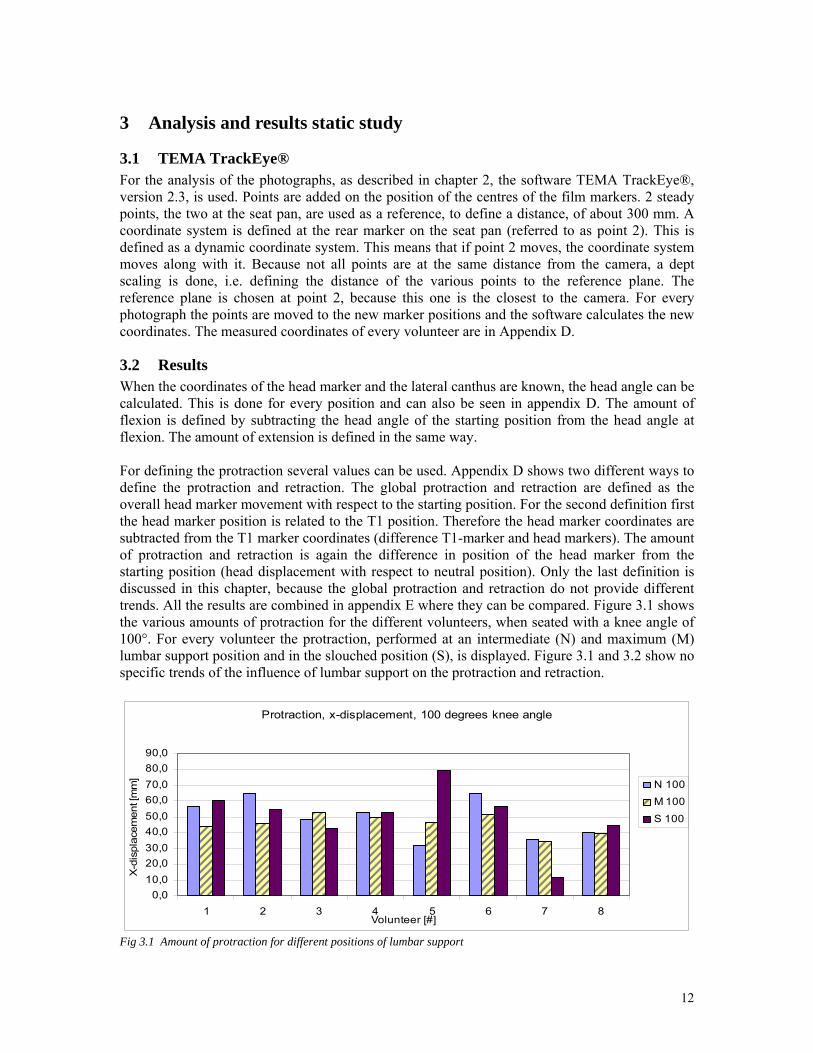
3.2 Results When the coordinates of the head marker and the lateral canthus are known, the head angle can be calculated. This is done for every position and can also be seen in appendix D. The amount of flexion is defined by subtracting the head angle of the starting position from the head angle at flexion. The amount of extension is defined in the same way. For defining the protraction several values can be used. Appendix D shows two different ways to define the protraction and retraction. The global protraction and retraction are defined as the overall head marker movement with respect to the starting position. For the second definition first the head marker position is related to the T1 position. Therefore the head marker coordinates are subtracted from the T1 marker coordinates (difference T1-marker and head markers). The amount of protraction and retraction is again the difference in position of the head marker from the starting position (head displacement with respect to neutral position). Only the last definition is discussed in this chapter, because the global protraction and retraction do not provide different trends. All the results are combined in appendix E where they can be compared. Figure 3.1 shows the various amounts of protraction for the different volunteers, when seated with a knee angle of 100°. For every volunteer the protraction, performed at an intermediate (N) and maximum (M) lumbar support position and in the slouched position (S), is displayed. Figure 3.1 and 3.2 show no specific trends of the influence of lumbar support on the protraction and retraction.
Protraction, x-displacement, 100 degrees knee angle
0,010,020,030,040,050,060,070,080,090,0
1 2 3 4 5 6 7 8Volunteer [#]
X-d
ispl
acem
ent [
mm
] N 100M 100
S 100
Fig 3.1 Amount of protraction for different positions of lumbar support
12
Retraction, x-displacement, 100 degrees knee angle
0,010,020,030,040,050,060,070,080,090,0
100,0
1 2 3 4 5 6 7 8volunteer [#]
X-d
ispl
acem
ent [
mm
] N 100M 100
S 100
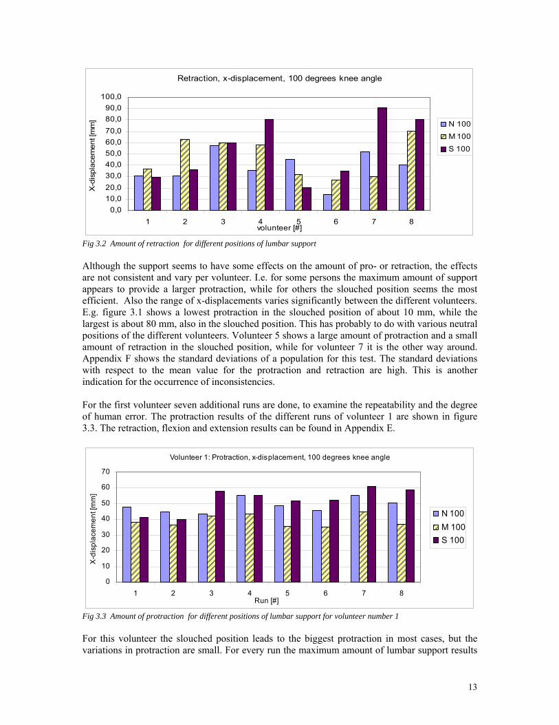
Fig 3.2 Amount of retraction for different positions of lumbar support Although the support seems to have some effects on the amount of pro- or retraction, the effects are not consistent and vary per volunteer. I.e. for some persons the maximum amount of support appears to provide a larger protraction, while for others the slouched position seems the most efficient. Also the range of x-displacements varies significantly between the different volunteers. E.g. figure 3.1 shows a lowest protraction in the slouched position of about 10 mm, while the largest is about 80 mm, also in the slouched position. This has probably to do with various neutral positions of the different volunteers. Volunteer 5 shows a large amount of protraction and a small amount of retraction in the slouched position, while for volunteer 7 it is the other way around. Appendix F shows the standard deviations of a population for this test. The standard deviations with respect to the mean value for the protraction and retraction are high. This is another indication for the occurrence of inconsistencies. For the first volunteer seven additional runs are done, to examine the repeatability and the degree of human error. The protraction results of the different runs of volunteer 1 are shown in figure 3.3. The retraction, flexion and extension results can be found in Appendix E.
Volunteer 1: Protraction, x-displacement, 100 degrees knee angle
0
10
20
30
40
50
60
70
1 2 3 4 5 6 7 8Run [#]
X-d
ispl
acem
ent [
mm
]
N 100M 100S 100
Fig 3.3 Amount of protraction for different positions of lumbar support for volunteer number 1 For this volunteer the slouched position leads to the biggest protraction in most cases, but the variations in protraction are small. For every run the maximum amount of lumbar support results
13
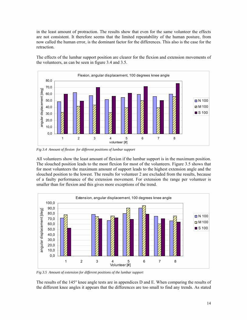
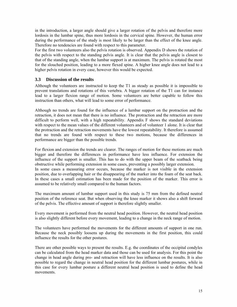
in the least amount of protraction. The results show that even for the same volunteer the effects are not consistent. It therefore seems that the limited repeatability of the human posture, from now called the human error, is the dominant factor for the differences. This also is the case for the retraction. The effects of the lumbar support position are clearer for the flexion and extension movements of the volunteers, as can be seen in figure 3.4 and 3.5.
Flexion, angular displacement, 100 degrees knee angle
0,0
10,0
20,0
30,0
40,0
50,0
60,0
70,0
80,0
1 2 3 4 5 6 7 8volunteer [#]
angu
lar d
ispl
acem
ent [
deg]
N 100
M 100
S 100
Fig 3.4 Amount of flexion for different positions of lumbar support All volunteers show the least amount of flexion if the lumbar support is in the maximum position. The slouched position leads to the most flexion for most of the volunteers. Figure 3.5 shows that for most volunteers the maximum amount of support leads to the highest extension angle and the slouched position to the lowest. The results for volunteer 2 are excluded from the results, because of a faulty performance of the extension movement. For extension the range per volunteer is smaller than for flexion and this gives more exceptions of the trend.
Extension, angular displacement, 100 degrees knee angle
0,010,020,030,040,050,060,070,080,090,0
100,0
1 2 3 4 5 6 7 8Volunteer [#]
angu
lar d
ispl
acem
ent [
deg]
N 100
M 100
S 100
Fig 3.5 Amount of extension for different positions of the lumbar support The results of the 145° knee angle tests are in appendices D and E. When comparing the results of the different knee angles it appears that the differences are too small to find any trends. As stated
14
in the introduction, a larger angle should give a larger rotation of the pelvis and therefore more lordosis in the lumbar spine, thus more lordosis in the cervical spine. However, the human error during the performance of the study is most likely to be larger than the effect of the knee angle. Therefore no tendencies are found with respect to this parameter. For the first two volunteers also the pelvis rotation is observed. Appendix D shows the rotation of the pelvis with respect to the standing pelvis angle. It is clear that the pelvis angle is closest to that of the standing angle, when the lumbar support is at maximum. The pelvis is rotated the most for the slouched position, leading to a more flexed spine. A higher knee angle does not lead to a higher pelvis rotation in every case, however this would be expected.
3.3 Discussion of the results Although the volunteers are instructed to keep the T1 as steady as possible it is impossible to prevent translations and rotations of this vertebra. A bigger rotation of the T1 can for instance lead to a larger flexion range of motion. Some volunteers are better capable to follow this instruction than others, what will lead to some error of performance. Although no trends are found for the influence of a lumbar support on the protraction and the retraction, it does not mean that there is no influence. The protraction and the retraction are more difficult to perform well, with a high repeatability. Appendix F shows the standard deviations with respect to the mean values of the different volunteers and of volunteer 1 alone. It is clear that the protraction and the retraction movements have the lowest repeatability. It therefore is assumed that no trends are found with respect to these two motions, because the differences in performance are bigger than the possible trends. For flexion and extension the trends are clearer. The ranges of motion for these motions are much bigger and therefore the differences in performance have less influence. For extension the influence of the support is smaller. This has to do with the upper beam of the seatback being obstructive while performing extension in some cases, preventing a possibly larger extension. In some cases a measuring error occurs, because the marker is not visible in the extension position, due to overlapping hair or the disappearing of the marker into the foam of the seat back. In these cases a small estimation has been made for the position of the marker. This error is assumed to be relatively small compared to the human factors. The maximum amount of lumbar support used in this study is 75 mm from the defined neutral position of the reference seat. But when observing the knee marker it shows also a shift forward of the pelvis. The effective amount of support is therefore slightly smaller. Every movement is performed from the neutral head position. However, the neutral head position is also slightly different before every movement, leading to a change in the neck range of motion. The volunteers have performed the movements for the different amounts of support in one run. Because the neck possibly loosens up during the movements in the first position, this could influence the results for the other postures. There are other possible ways to present the results. E.g. the coordinates of the occipital condyles can be calculated from the head marker data and those can be used for analysis. For this point the change in head angle during pro- and retraction will have less influence on the results. It is also possible to regard the change in neutral head position for the different lumbar postures, while in this case for every lumbar posture a different neutral head position is used to define the head movements.
15
4 Test set-up dynamic study: Low speed frontal impact
4.1 Description of the test The aim of the low speed frontal impact test is to examine the movement of the lumbar spine of humans in a frontal impact. In order to obtain a safe and well repeatable test, a low speed crash sled is used. This type of sled is used by the Swedish National Society for Road Safety in traffic safety education, stressing the importance of wearing a seat belt. The sled has an impact speed of approximately 7 km/h, which is considered to be a harmless impact speed for a belted person. Appendix H shows sled decelerations of about 16G. This appears to be a high value for a volunteer test. This deceleration however only takes place during a very short amount of time (with a maximum of 20 ms) and is mainly caused by the rigid impact structure. The basic design of the sled is a car seat mounted on a platform with a fixture for a three point seat belt. The platform has wheels that run in tracks arranged in a slope in a larger structure. The desired outcome of the sled test is translational data of the lumbar spine movement, as well as acceleration data for the sled and the volunteers. The seated posture in the sled resembles a driving posture. Accelerometers and film markers are mounted on both the sled and on the volunteers. The accelerometer data is gathered with a data acquisition system and the impact is captured by a high speed video camera.
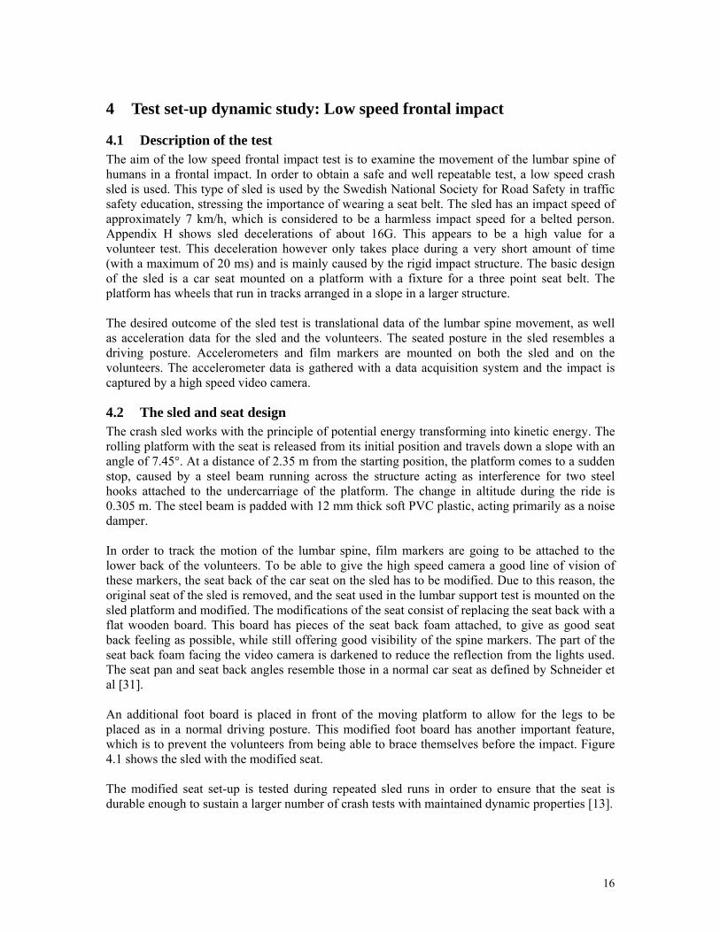
4.2 The sled and seat design The crash sled works with the principle of potential energy transforming into kinetic energy. The rolling platform with the seat is released from its initial position and travels down a slope with an angle of 7.45°. At a distance of 2.35 m from the starting position, the platform comes to a sudden stop, caused by a steel beam running across the structure acting as interference for two steel hooks attached to the undercarriage of the platform. The change in altitude during the ride is 0.305 m. The steel beam is padded with 12 mm thick soft PVC plastic, acting primarily as a noise damper. In order to track the motion of the lumbar spine, film markers are going to be attached to the lower back of the volunteers. To be able to give the high speed camera a good line of vision of these markers, the seat back of the car seat on the sled has to be modified. Due to this reason, the original seat of the sled is removed, and the seat used in the lumbar support test is mounted on the sled platform and modified. The modifications of the seat consist of replacing the seat back with a flat wooden board. This board has pieces of the seat back foam attached, to give as good seat back feeling as possible, while still offering good visibility of the spine markers. The part of the seat back foam facing the video camera is darkened to reduce the reflection from the lights used. The seat pan and seat back angles resemble those in a normal car seat as defined by Schneider et al [31]. An additional foot board is placed in front of the moving platform to allow for the legs to be placed as in a normal driving posture. This modified foot board has another important feature, which is to prevent the volunteers from being able to brace themselves before the impact. Figure 4.1 shows the sled with the modified seat. The modified seat set-up is tested during repeated sled runs in order to ensure that the seat is durable enough to sustain a larger number of crash tests with maintained dynamic properties [13].
16
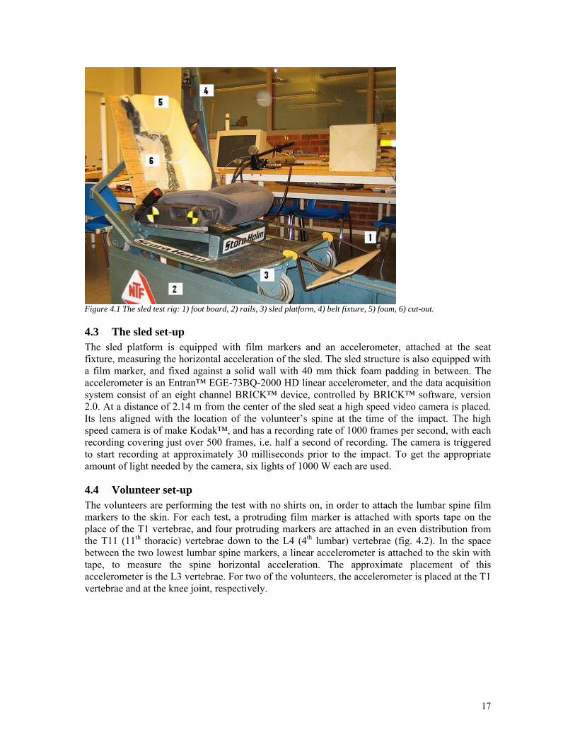
Figure 4.1 The sled test rig: 1) foot board, 2) rails, 3) sled platform, 4) belt fixture, 5) foam, 6) cut-out.
4.3 The sled set-up The sled platform is equipped with film markers and an accelerometer, attached at the seat fixture, measuring the horizontal acceleration of the sled. The sled structure is also equipped with a film marker, and fixed against a solid wall with 40 mm thick foam padding in between. The accelerometer is an Entran™ EGE-73BQ-2000 HD linear accelerometer, and the data acquisition system consist of an eight channel BRICK™ device, controlled by BRICK™ software, version 2.0. At a distance of 2.14 m from the center of the sled seat a high speed video camera is placed. Its lens aligned with the location of the volunteer’s spine at the time of the impact. The high speed camera is of make Kodak™, and has a recording rate of 1000 frames per second, with each recording covering just over 500 frames, i.e. half a second of recording. The camera is triggered to start recording at approximately 30 milliseconds prior to the impact. To get the appropriate amount of light needed by the camera, six lights of 1000 W each are used.
4.4 Volunteer set-up The volunteers are performing the test with no shirts on, in order to attach the lumbar spine film markers to the skin. For each test, a protruding film marker is attached with sports tape on the place of the T1 vertebrae, and four protruding markers are attached in an even distribution from the T11 (11th thoracic) vertebrae down to the L4 (4th lumbar) vertebrae (fig. 4.2). In the space between the two lowest lumbar spine markers, a linear accelerometer is attached to the skin with tape, to measure the spine horizontal acceleration. The approximate placement of this accelerometer is the L3 vertebrae. For two of the volunteers, the accelerometer is placed at the T1 vertebrae and at the knee joint, respectively.
17
Figure 4.2 Volunteer seated in test rig with film markers attached
4.4.1 Instructions to the volunteers At the introduction of the test set-up, the volunteers are informed in how the sled is functioning, and what the objectives with the test are. They are instructed in how to perform the test in the following procedure:
- While seated with the back against the modified seat back and the markers attached to the spine, try to keep as normal seated posture as possible, using the remaining seat back foam as support.
- Try not to exert pressure on the markers against the seat back wooden board. - Keep the hands on the thighs with arms relaxed during the ride. - Keep the mouth closed and look straight ahead during the ride. - Try to be as relaxed as possible during the ride, not tensing any muscles. - Keep the feet placed on the modified foot board during the entire ride.
4.4.2 Volunteer data The desired anthropometry of the volunteers is, just as in the first study of the lumbar support, the 50th percentile male with a stature of 1.78 m and a weight of 77 kg [30]. The number of volunteers is also kept at eight individual persons in this test. Due to the nature of the test, it is verified that the volunteers do not have any medical problems related to the neck or the back. The stature, weight and age data of the volunteers in this test are displayed in table 4.1.
Table 4.1 Volunteer data for the low speed frontal impact study Volunteer # Stature Weight Age
1 180 cm 83 kg 27 yrs 2 173 cm 68 kg 25 yrs 3 178 cm 69 kg 24 yrs 4 181 cm 91 kg 24 yrs 5 184 cm 80 kg 26 yrs 6 183 cm 76 kg 22 yrs 7 185 cm 78 kg 26 yrs 8 183 cm 70 kg 27 yrs
Mean value µ 180,88 cm 76,88 kg 25,13 yrs Standard deviation σ 3,66 cm 7,39 kg 1,62 yrs
18
4.5 The execution of the test With the volunteer seated and instructed, the data acquisition system and the high speed video camera is made ready to record data. After ready signals from both of the systems, the lights are turned on and the volunteer is asked if he is ready. After this the sled is released from its initial starting position, and travels down to the awaiting impact at the end position. The sled platform is then pulled back to the starting position, with the volunteer still seated. After checking the condition of the markers, the volunteer has his seating position readjusted to the same as in the previous run. Then the procedure is repeated and each volunteer goes through three runs of the test.
4.6 Conditions and assumptions This paragraph will describe some of the assumptions that are made, to explain some choices and the testing conditions.
- Again the tests are not all done at the same time, i.e. in the morning or the afternoon. The same assumption is made as for the static test.
- For the second task the end of the rebound phase is not fully correct of even analyzed, because of the invisibility of the markers at the end of the rebound phase in some cases.
- Because of the inclination of the sled rail, there is also a downward speed. This will lead to a spine movement going slightly more downward and being more compressed during impact than it will in a fully horizontal crash.
- Only a full overlap impact is simulated. For impacts under an angle the spine behavior is probably different.
- The instrumentation and the markers are assumed to be light enough to have no influence on the behavior of the volunteers.
- The same seatbelt is used for each test. This could lead to elongation of the belt. Assumed is that this can be neglected.
- Especially the arms are not in a real driving position. This could influence the neck and spine behavior.
- The markers on the spine and the lack of foam prevent the volunteer to sit fully relaxed and force him to sit in a slightly altered seated position. This effect is assumed to be neglectable.
All these conditions and assumption may cause slightly different results, than those that would be found in a real crash situation.
19
5 Analysis and results dynamic study
5.1 TEMA TrackEye® For the analysis of the dynamic study again TEMA TrackEye® is used. The input of the program now is a high speed movie, instead of photographs. The principle of using the software is the same as for the static study. Again two markers at the seat pan are used as a reference, to define a distance, of 234 mm. The coordinate system is defined as static at the starting position of point 2, the rear seat pan marker. The dept scaling is done, as before. The reference plane is chosen at the marker point on the rail. For every frame the new marker positions are tracked by the software. The results are presented in diagrams, shown in appendix G.
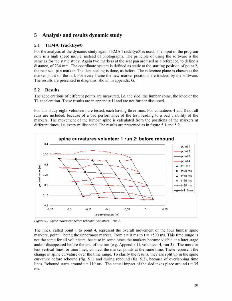
5.2 Results The accelerations of different points are measured, i.e. the sled, the lumbar spine, the knee or the T1 acceleration. These results are in appendix H and are not further discussed. For this study eight volunteers are tested, each having three runs. For volunteers 4 and 8 not all runs are included, because of a bad performance of the test, leading to a bad visibility of the markers. The movement of the lumbar spine is calculated from the positions of the markers at different times, i.e. every millisecond. The results are presented as in figure 5.1 and 5.2.
spine curvatures volunteer 1 run 2: before rebound
0,1
0,15
0,2
0,25
0,3
0,35
0,4
-0,25 -0,2 -0,15 -0,1 -0,05 0 0,05
x-coordinates [m]
y-co
ordi
nate
s [m
]
point 1point 2
point 3point 4t=0 ms
t=20 mst=40 ms
t=60 mst=80 ms
t=110 ms
Figure 5.1 Spine movement before rebound: volunteer 1 run 2 The lines, called point 1 to point 4, represent the overall movement of the four lumbar spine markers, point 1 being the uppermost marker. From t = 0 ms to t = ±500 ms. This time range is not the same for all volunteers, because in some cases the markers became visible at a later stage and/or disappeared before the end of the run (e.g. Appendix G, volunteer 4, run 3). The more or less vertical lines, or time lines, connect the marker points at the same time. These represent the change in spine curvature over the time range. To clarify the results, they are split up in the spine curvature before rebound (fig. 5.1) and during rebound (fig. 5.2), because of overlapping time lines. Rebound starts around t = 110 ms. The actual impact of the sled takes place around t = 35 ms.
20
spine curvatures volunteer 1 run 2: during rebound
0,1
0,15
0,2
0,25
0,3
0,35
0,4
-0,25 -0,2 -0,15 -0,1 -0,05 0 0,05
x-coordinates [m]
y-co
ordi
nate
s [m
]
point 1
point 2
point 3
point 4
t=120 ms
t=190 ms
t=260 ms
t=330 ms
t=400 ms
t=470 ms
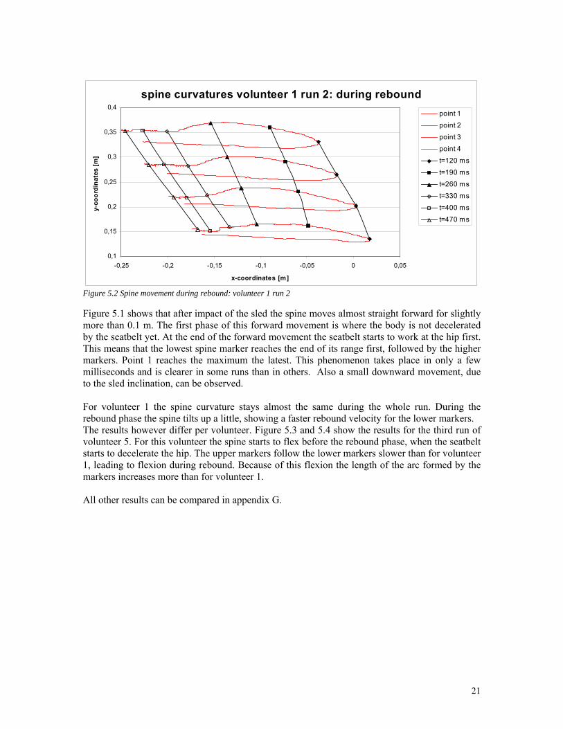
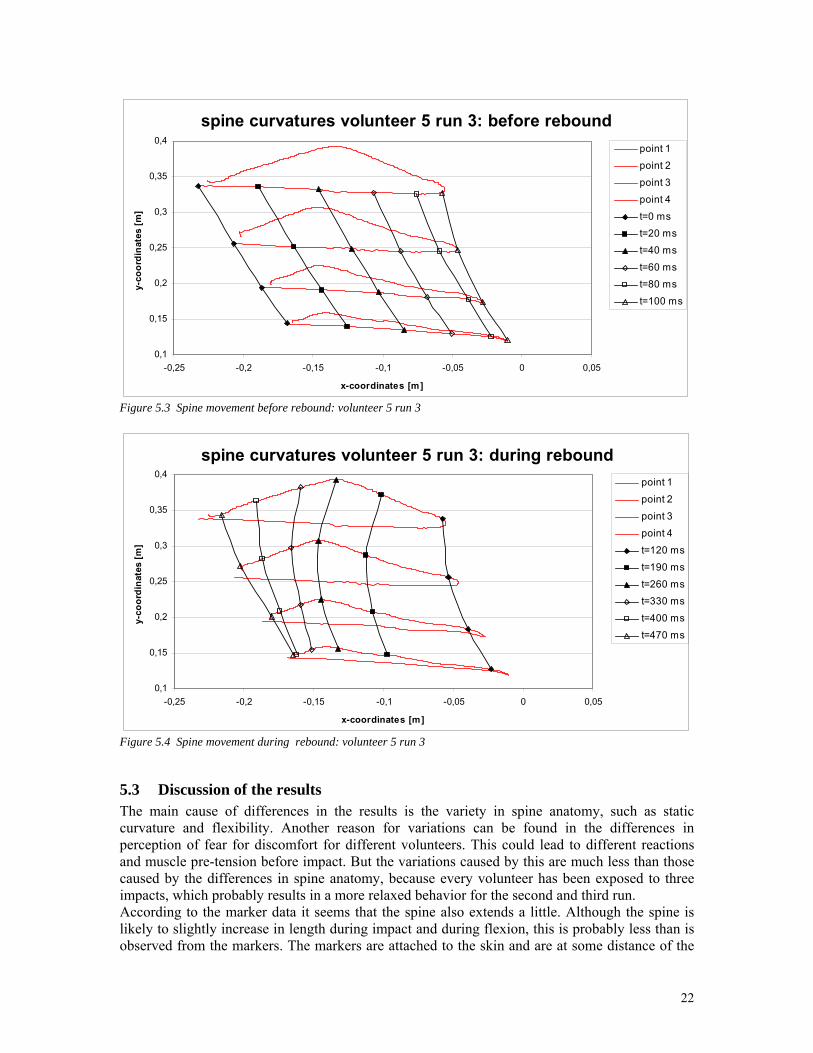
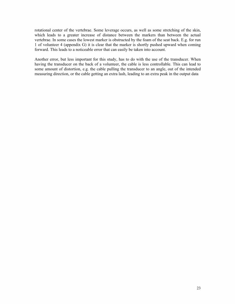
Figure 5.2 Spine movement during rebound: volunteer 1 run 2 Figure 5.1 shows that after impact of the sled the spine moves almost straight forward for slightly more than 0.1 m. The first phase of this forward movement is where the body is not decelerated by the seatbelt yet. At the end of the forward movement the seatbelt starts to work at the hip first. This means that the lowest spine marker reaches the end of its range first, followed by the higher markers. Point 1 reaches the maximum the latest. This phenomenon takes place in only a few milliseconds and is clearer in some runs than in others. Also a small downward movement, due to the sled inclination, can be observed. For volunteer 1 the spine curvature stays almost the same during the whole run. During the rebound phase the spine tilts up a little, showing a faster rebound velocity for the lower markers. The results however differ per volunteer. Figure 5.3 and 5.4 show the results for the third run of volunteer 5. For this volunteer the spine starts to flex before the rebound phase, when the seatbelt starts to decelerate the hip. The upper markers follow the lower markers slower than for volunteer 1, leading to flexion during rebound. Because of this flexion the length of the arc formed by the markers increases more than for volunteer 1. All other results can be compared in appendix G.
21
spine curvatures volunteer 5 run 3: before rebound
0,1
0,15
0,2
0,25
0,3
0,35
0,4
-0,25 -0,2 -0,15 -0,1 -0,05 0 0,05
x-coordinates [m]
y-co
ordi
nate
s [m
]point 1point 2
point 3point 4
t=0 mst=20 mst=40 ms
t=60 mst=80 ms
t=100 ms
Figure 5.3 Spine movement before rebound: volunteer 5 run 3
spine curvatures volunteer 5 run 3: during rebound
0,1
0,15
0,2
0,25
0,3
0,35
0,4
-0,25 -0,2 -0,15 -0,1 -0,05 0 0,05
x-coordinates [m]
y-co
ordi
nate
s [m
]
point 1
point 2
point 3
point 4
t=120 ms
t=190 ms
t=260 mst=330 ms
t=400 ms
t=470 ms
Figure 5.4 Spine movement during rebound: volunteer 5 run 3
5.3 Discussion of the results The main cause of differences in the results is the variety in spine anatomy, such as static curvature and flexibility. Another reason for variations can be found in the differences in perception of fear for discomfort for different volunteers. This could lead to different reactions and muscle pre-tension before impact. But the variations caused by this are much less than those caused by the differences in spine anatomy, because every volunteer has been exposed to three impacts, which probably results in a more relaxed behavior for the second and third run. According to the marker data it seems that the spine also extends a little. Although the spine is likely to slightly increase in length during impact and during flexion, this is probably less than is observed from the markers. The markers are attached to the skin and are at some distance of the
22
rotational center of the vertebrae. Some leverage occurs, as well as some stretching of the skin, which leads to a greater increase of distance between the markers than between the actual vertebrae. In some cases the lowest marker is obstructed by the foam of the seat back. E.g. for run 1 of volunteer 4 (appendix G) it is clear that the marker is shortly pushed upward when coming forward. This leads to a noticeable error that can easily be taken into account. Another error, but less important for this study, has to do with the use of the transducer. When having the transducer on the back of a volunteer, the cable is less controllable. This can lead to some amount of distortion, e.g. the cable pulling the transducer to an angle, out of the intended measuring direction, or the cable getting an extra lash, leading to an extra peak in the output data
23
6 General discussion Working with volunteers is always difficult. This has various causes. First of all the results depend on the dedication of the volunteer and how well he follows the given instructions. For the static test e.g. the maximum protraction will be interpreted different by different volunteers. Some will end the protraction movement when it still feels comfortable, while others will go one step further, beyond a comfortable position. This of course also is the case for all the other movements. Furthermore, there are anatomical differences between the volunteers, what could lead to less movement in one and more movement in another direction compared to other volunteers. Also the pain threshold or rather the level of discomfort differs per person. All these differences will lead to a slightly different execution of the instructions. For the second task the influence of these things are much less. The physical condition of the volunteers is not considered in both studies. The results are possibly different for fitter volunteers, than for volunteers with a lesser condition. Also the kind of sport, performed by a volunteer, could influence the flexibility of the volunteer and therefore the results. For both tasks film markers form an essential part of the analyses. However, the use of markers also leads to errors. Markers are attached to the skin and not to the vertebrae. Because the skin is able to stretch and move with respect to the vertebrae, this gives a slight difference in results. Another problem that occurs because of this is a possible rotation, and therefore a small upward or downward translation, of the markers, due to the stretching or crumbling of the skin. In some cases the markers are slightly obstructed by the seatback or even by the head and neck skin, for extension positions. The positioning of a marker on the T1 or any other place is always estimation. Especially for the second task, the markers are not placed on the exact same vertebrae for all the volunteers, but rather distributed evenly along the spine. The use of the TEMA TrackEye® also leads to several errors. Because the results depend on the given depth scaling in the program, variations of the marker distances to the camera will lead to a calculation error. Although the same configuration and the same depth scaling are used for all volunteers, the exact same distance to the camera is hard to maintain. Some volunteers will be seated a little out of the center of the seat. The error because of the depth scaling is calculated in appendix A and is at maximum about 2% [22]. Another error that occurs when using TEMA TrackEye® is dependent on the accuracy of pointing the location of a marker. In appendix C a calculation is made for the repeatability and accuracy of manually defining the points to be measured. The maximum error found is 1.17%. Further research Some further research is recommended for the near future. This study itself can be enlarged, because of the simplifications made. I.e. only men in a certain age and stature group are tested. In future study the variation in volunteers can be enlarged. Women should be analyzed as well as smaller, larger, older and younger volunteers. Probably there will be slightly different results for the various groups.
24
A second simplification in this study is the use of markers and the assumption that markers represent the vertebrae well enough. It is very hard however to define vertebrae rotation correctly. Therefore x-ray analysis could be done to have a clearer view of these rotations. A different research that could be done in the future is a dynamic study of the static study as described in this report. I.e. various impact tests, frontal and rear-end, for different amounts of lumbar support. This would decrease the human error with respect to the protraction and retraction range and could give a clearer view of the influence of the support on these movements. As mentioned in the introduction, all of these studies can be used for validation or enhancement of the lumbar region on crash dummies.
25
7 Conclusions To study the influence of a lumbar support on the neck range of motion a test rig is developed. This test rig allows a big range of amount of lumbar support, from a slouched seating position to a position with a significant amount of support for the lumbar region. Assuming that WAD occur at the end of the natural neck range of motion, i.e. protraction, flexion, retraction and extension, static tests are done using volunteers to study the influence of this support on these neck motions. Trends are found for the influence of the support on the flexion and extension range of motion performed by the volunteers, taking different seated postures. The maximum amount of lumbar support leads to the smallest range of flexion for every volunteer and in most of the cases to the largest amount of extension. The slouched position provides the largest amount of flexion and smallest amount of extension for most of the volunteers. For extension the ranges of motion are smaller, leading to more inconsistencies. The support does not influence the range of protraction and retraction motion consistently for the different volunteers or even for one volunteer, probably because of human errors while performing these motions that are in the same range of the possible trends. Possibly the support has an effect on the protraction and retraction range of motion, but this should be further investigated in a future study in which these motions are better controlled, with less chance of errors. It seems that the lumbar support can influence the occurrence of neck injuries in traffic accidents. The influence seems positive for rear-end impacts (extension), while a lumbar support has a negative effect during a frontal impact (flexion). Therefore an active lumbar support, changing the lumbar posture to the best suitable one depending on the impact direction, could possibly be a good safety feature in the future. The behavior of the lumbar spine during a frontal collision is also studied. Again a test rig is developed, which included a sled and a car seat, with an adjusted seat back to allow a good visibility of the film markers, attached to the lumbar spine vertebrae. A high speed camera provides a high frequency movie that can be analyzed. Results show differences in spine anatomy at the starting position, as well as different spine motions for the different volunteers. In most of the cases the lumbar spine flexes, starting at the beginning of the rebound phase, or just before that. The results are highly dependent of the initial anatomy and the flexibility of the spine of the volunteer. Errors occur because of the use of markers attached to the skin, leading to an analyzed movement of the skin, rather than of the vertebrae themselves.
26
References [1] Foreman, S.M., Croft, A.C. (1988) Whiplash injuries, the cervical accelleration/deceleration syndrome, Williams & Wilkins, Baltimore, ISBN 0-683-03314-X. [2] Rothman, R.H., Simeone, F.A. (1982) The Spine, W.B. Saunders Company, Philadelphia, ISBN 0-7216-7718-5. [3] Caillet, R. (1985) Neck and arm pain, 2nd edition, F.H. Davis Company, Philadelphia, ISBN 0-8036-1609-0. [4] McMinn, R.M.H., Hutchings, R.T., Logan, B.M. (1985) A colour atlas of head and neck anatomy, Wolfe Medical Publications Ltd, Weert, ISBN 0-7234-0755-X. [5] Nahum, A.M., Melvin, J.W. (1993) Accidental injury, Biomechanics and prevention, Springer Verlag New York Inc, New York, ISBN 3-540-97881-X. [6] Sherk, H.H., Dunn, E.J., Eismont, F.J., Fielding, J.W., Long, D.M., Ono, K., Penning, L., Raynor, R. (1989) The cervical spine, 2nd edition, J.B. Lippincott Company, Philadelphia, ISBN 0-397-50827-1. [7] Jakobsson, L. (2004) Whiplash associated disorders in frontal and rear-end car impacts: Biomechanical guidelines and evaluation criteria based on accident data and occupant modelling, Doctoral thesis for the degree of Doctor of Philosophy, Crash Safety Division, Department of Machine and Vehicle Design, Chalmers University of Technology, Göteborg, Sweden, Serial No. 2091, ISBN 91-7291-409-2. [8] DeSantis Klinich, K., Ebert, S.M., Van Ee, C.A., Flannagan, C.A.C., Prasad, M., Reed, M.P., Schneider, L.W. (2004) Cervical Spine Geometry in the Automotive Seated Posture: Variations with Age, Stature, and Gender, University of Michigan Transportation Research Institute, Paper, Stapp Car Crash Journal, Vol. 48, The Stapp Association. [9] Boström, O., Håland, Y., Fredriksson, R., Svensson, M.Y., Mellander, H. (1998) A sled test procedure proposal to evaluate the risk of neck injury in low speed rear impacts using a new neck injury criterion (NIC), Paper no. 98-S7-O-07, Procs. of the 16th Int. Technical Conf. on the Enhanced Safety of Vehicles, 1579-1585. [10] Cappon H., Philippens, M., Wismans, J. A new test method for the assessment of neck injuries in rear-end collisions, Paper no. 242, TNO Automotive, The Netherlands. [11] Viano, D.C. (2002) Role of the seat in rear crash safety, Society of Automotive Engineers, Inc, Warrendale, ISBN 0-7680-0847-6 [12] Davidsson, J. (2000) Development of a Mechanical Model for Rear Impacts: Evaluation of Volunteer Responses and Validation of the model, Doctoral thesis for the degree of Doctor of Philosophy, Crash Safety Division, Department of Machine and Vehicle Design, Chalmers University of Technology, Göteborg, Sweden, Serial No. 1608, ISBN 91-7197-924-7.
27
[13] Cappon H., Van Ratingen, M., Wismans, J., Hell, W., Lang, D., Svensson, M. Whiplash injuries, not only a problem in rear-end impact, Paper no. 214, TNO Automotive, The Netherlands, German institute for Vehicle safety, Germany, Chalmers University of Technology, Sweden. [14] (1996) Loss of the Lumbar Curve in the Driving Seat, A Twenty Person Study, Paper, British Osteopathic Journal Vol. XIX, pp. 19-23. [15] Eriksson, L. (2004) Neck Injury Risk in Rear-End Impacts, Risk Factors and Neck Injury Criterion Evaluation with Madymo Modelling and Real-Life Data, Doctoral thesis for the degree of Doctor of Philosophy, Crash Safety Division, Department of Machine and Vehicle Design, Chalmers University of Technology, Göteborg, Sweden, ISBN 91-7291-544-7. [16] Svensson, M.Y., Boström, O., Davidsson, J., Hansson, H.-A., Håland, Y., Lövsund, Suneson, A., Säljö, A. (1999) Neck injuries in car collisions – a review covering a possible injury mechanism and the development of a new rear-impact dummy, Paper as presented at The 1999 Whiplash Associated Disrders World Congress, Vancouver. [17] Chabert, L., Ghannouchi, S., Cavallero, C., Geometrical Characterisation of a Seated Occupant, Paper no. 98-S9-P-19. [18] Thunnissen, J., Wismans, J., Ewing, C.L., Thomas, D.J. (1995) Human Volunteer Head-Neck Response in Frontal Flexion: A New Analysis, SAE Paper 952721, Society of Automotive Engineers, Inc. [19] Kroonenberg, A. van den, Philippens, M., Cappon, H., Wismans, J., Hell, W., Langwieder, K. (1998) Human Head-Neck Response During Low-Speed Rear End Impacts, SAE Paper 983158, 42nd Stapp Car Crash Conference Proceedings, Society of Automotive Engineers, Inc., USA. [20] Siegmund, G.P., King, D.J., Lawrence, J.M., and Wheeler, J.B., Brault, J.R., Smith, T.A. (1997) Head/Neck Kinematic response of Human Subjects in Low-Speed Rear-End Collisions, SAE Paper 973341, Proceedings 41th SPAPP Car Crash Conference Proceedings, Society of Automotive Engineers, Inc., USA. [21] Holmqvist, K., Martinsson, J. (2004) Analysis of the range of motion of the shoulder during static loading, Master thesis for the degree of Master of Engineering, Crash Safety Division, Department of Machine and Vehicle Design, Chalmers University of Technology, Göteborg, Sweden.. [22] Walker, L.B., Harris, E.H., Pontius, U.R. (1973) Mass, Volume, Center of Mass, and Mass Moment of Inertia of Head and Head and Neck of Human Body, SAE Paper 730985, 17th Stapp Car Crash Conference, Tulane University. [23] Reed, M.P., Schneider, L.W., Eby, B.A.H. (1995) Some Effects of Lumbar Support Contour on Driver Seated Posture, SAE Paper 950141, Society of Automotive Engineers, Inc., USA. [24] Reed, M.P., Schneider, L.W. (1996) Lumbar Support in Auto Seats: Conclusions from a Study of Preferred Driving Posture, SAE Paper 960478, Society of Automotive Engineers, Inc., USA.
28
[25] Brodeur, R.R., Cui, Y., Reynolds, H.M. (1996) Locating the Pelvis in the Seated Automobile drive, SAE Paper 960481, Society of Automotive Engineers, Inc., USA. [26] Nusholtz, G.S., Alem, N.M., Melvin, J.W. (1982) Pelvic tolerance and protection criteria in side impact, SAE Paper 821159, 26th Stapp Car Crash Conference, Society of Automotive Engineers, Inc., USA. [27] Lee, Y-H, Chiou, W-K, Chen, W-J, Lee, M-Y, Lin, Y-H. (1995) Predictive Model of Intersegmental Mobility of Lumbar Spine in the Saggital Plane From Skin Markers, Clinical Biomechanics, Vol. 10. No. 8, pp 413-420. [28] Society of Automotive Engineers, SAE J211 (1995), Instrumentation for Impact Test. [29] GMH Engineering (1996) Data BRICK System Reference Manual, document version 2.0 [30] Natick Labs (1988) Anthropometric Survey of US Army Personnel – Methods and summary statistics, Natick Technical Report TR-89-044 [31] Schneider, W.L., Foust, D.R., Bowman, B.M., Snyder, R.G., Chaffin, D.B., Abdelnour, T.A., Baum, J.K. (1975) Biomechanical Properties of the Human Neck in Lateral Flexion, SAE Paper 751156, 19th Stapp Car Crash Conference, Society of Automotive Engineers, Inc., USA. [32] Nygren, Å. (1984) Injuries to Car Occupants – Some Aspects of the Interior Safety of Cars – A study of Five-Years Material from an Insurance Company, Acta Oto – Laryngologica – Supppl.395, ISSN 0365-5237. [33] Barnsley, L., Lord, S.M., Bogduk, N. (1994) Clinical Review: Whiplash Injury, Pain 58, pp 283-307 [34] Morris, A.P., Thomas, P. (1996) A Study of Soft Tissue Neck Injuries in the UK, Paper No. 96-S9-O-08, Proc. Of the 15th Int. ESV Conf, pp 1412-1425. [35] Temming, J., Zobel, R. (2000) Neck Distortion Injuries in Road Traffic Crashes (Analyses of the Volkswagen Database), IOS Press, pp 118-133.
29
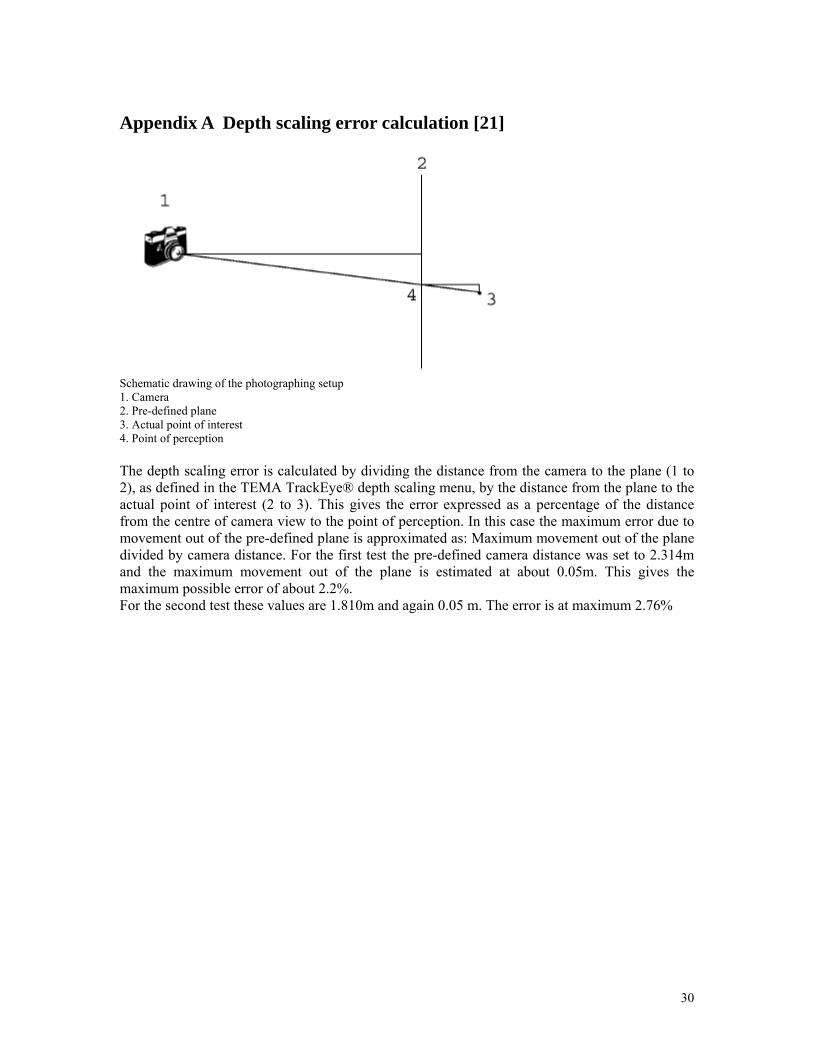
Appendix A Depth scaling error calculation [21]
Schematic drawing of the photographing setup 1. Camera 2. Pre-defined plane 3. Actual point of interest 4. Point of perception The depth scaling error is calculated by dividing the distance from the camera to the plane (1 to 2), as defined in the TEMA TrackEye® depth scaling menu, by the distance from the plane to the actual point of interest (2 to 3). This gives the error expressed as a percentage of the distance from the centre of camera view to the point of perception. In this case the maximum error due to movement out of the pre-defined plane is approximated as: Maximum movement out of the plane divided by camera distance. For the first test the pre-defined camera distance was set to 2.314m and the maximum movement out of the plane is estimated at about 0.05m. This gives the maximum possible error of about 2.2%. For the second test these values are 1.810m and again 0.05 m. The error is at maximum 2.76%
30
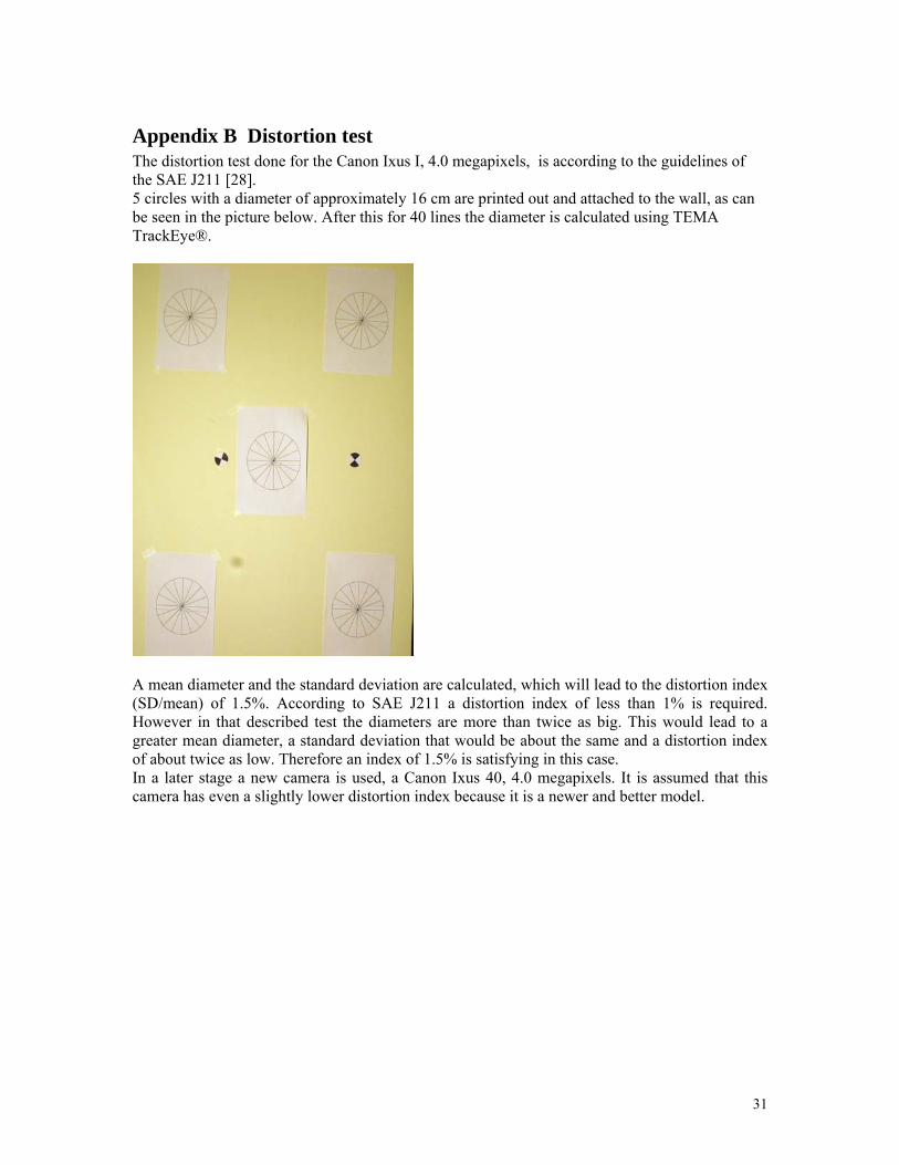
Appendix B Distortion test The distortion test done for the Canon Ixus I, 4.0 megapixels, is according to the guidelines of the SAE J211 [28]. 5 circles with a diameter of approximately 16 cm are printed out and attached to the wall, as can be seen in the picture below. After this for 40 lines the diameter is calculated using TEMA TrackEye®.
A mean diameter and the standard deviation are calculated, which will lead to the distortion index (SD/mean) of 1.5%. According to SAE J211 a distortion index of less than 1% is required. However in that described test the diameters are more than twice as big. This would lead to a greater mean diameter, a standard deviation that would be about the same and a distortion index of about twice as low. Therefore an index of 1.5% is satisfying in this case. In a later stage a new camera is used, a Canon Ixus 40, 4.0 megapixels. It is assumed that this camera has even a slightly lower distortion index because it is a newer and better model.
31
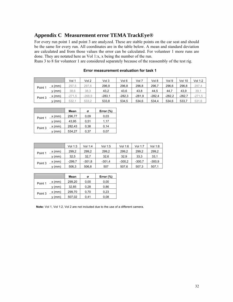
Appendix C Measurement error TEMA TrackEye® For every run point 1 and point 3 are analyzed. These are stable points on the car seat and should be the same for every run. All coordinates are in the table below. A mean and standard deviation are calculated and from those values the error can be calculated. For volunteer 1 more runs are done. They are notated here as Vol 1:x, x being the number of the run. Runs 3 to 8 for volunteer 1 are considered separately because of the reassembly of the test rig.
Error measurement evaluation for task 1
Vol 1 Vol 2 Vol 3 Vol 6 Vol 7 Vol 8 Vol 9 Vol 10 Vol 1:2 x (mm) 297,5 297,6 296,9 296,8 296,8 296,7 296,6 296,8 297,4 Point 1 y (mm) 38,6 38,3 43,2 43,6 43,8 44,5 44,7 43,9 39,1 x (mm) -271,5 -268,9 -283,1 -282,3 -281,9 -282,4 -282,2 -282,7 -271,5 Point 3 y (mm) 532,1 533,2 533,8 534,5 534,6 534,4 534,6 533,7 531,6
Mean σ Error (%)
x (mm) 296,77 0,09 0,03 Point 1 y (mm) 43,95 0,51 1,17 x (mm) 282,43 0,38 0,14 Point 3 y (mm) 534,27 0,37 0,07
Vol 1:3 Vol 1:4 Vol 1:5 Vol 1:6 Vol 1:7 Vol 1:8 x (mm) 299,2 299,2 299,2 299,2 299,2 299,2 Point 1 y (mm) 32,5 32,7 32,6 32,9 33,3 33,1 x (mm) -299,7 -301,8 -301,4 -300,2 -300,7 -300,9 Point 3 y (mm) 506,3 506,8 507 507,6 507,3 507,1
Mean σ Error (%)
x (mm) 299,20 0,00 0,00 Point 1 y (mm) 32,85 0,28 0,86 x (mm) 299,70 0,70 0,23 Point 3 y (mm) 507,02 0,41 0,08
Note: Vol 1, Vol 1:2, Vol 2 are not included due to the use of a different camera.
32
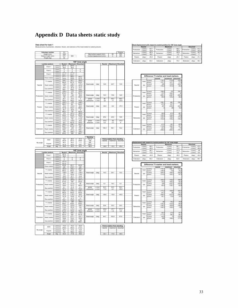
Appendix D Data sheets static study
x (mm) 47,7 x (mm) 38,2 x (mm) 41,3y (mm) -33,4 y (mm) -20,4 y (mm) -24,9
1.1 Position x (mm) -60,3 x (mm) -44,9 x (mm) -34,31805 60 0F5 y (mm) 18,2 y (mm) 1,3 y (mm) 7870 920 0 0F382
Neutral Maximum Slouched Neutral Maximum Slouchedx (mm) 297,5 297,5y (mm) 38,6 38,4x (mm) 0 0 0y (mm) 0 0 0x (mm) -271,5 -271,4y (mm) 532,1 532,1x (mm) 471,1 496,5 450,2y (mm) 233,4 230,5 221,5 neutral maximum slouchedx (mm) -244,7 -281,1 -260,8 x (mm) -119,1 -112,8 -123,4y (mm) 662,9 647,6 635,9 y(mm) -107,1 -121,1 -71,9x (mm) -125,6 -168,3 -137,4 Head angle (deg) 16,9 20,7 13,9 x (mm) -205 -193,6 -209,7y (mm) 770 768,7 707,8 y(mm) -133,2 -151,6 -93,3x (mm) -39,7 -87,5 -51,1y (mm) 796,1 799,2 729,2x (mm) -226,4 -273 -253,6 x (mm) -166,8 -151 -164,7y (mm) 674,3 657 637,3 y(mm) -73,7 -100,7 -47x (mm) -59,6 -122 -88,9 Head angle (deg) 10,4 15,6 12,9 x (mm) -255,1 -238,7 -250,6y (mm) 748 757,7 684,3 y(mm) -89,9 -125,2 -66,6x (mm) 28,7 -34,3 -3 global x (mm) 66 46,3 48,5y (mm) 764,2 782,2 703,9 protraction y (mm) -22 -11 -23,5x (mm) -220,3 -270 -248,5 x (mm) -185,1 -86,1 -182,2y (mm) 680,3 661 640,4 y(mm) -47,5 -91,7 -28x (mm) -35,2 -183,9 -66,3 Head angle (deg) -34,0 -8,4 -37,3 x (mm) -251 -239,5 -244,5y (mm) 727,8 752,7 668,4 y(mm) -3 -69 19,5x (mm) 30,7 -30,5 -4y (mm) 683,3 730 620,9x (mm) -272 -291,2 -263,9 x (mm) -58,8 -67,9 -89,1y (mm) 649,2 642,6 634,9 y(mm) -125,3 -122,4 -78,9x (mm) -213,2 -223,3 -174,8 Head angle (deg) 25,2 24,0 19,8 x (mm) -140,7 -150,4 -173,5y (mm) 774,5 765 713,8 y(mm) -163,8 -159,2 -109,3x (mm) -131,3 -140,8 -90,4 global x (mm) -87,6 -55 -37,4y (mm) 813 801,8 744,2 retraction y (mm) 4,5 -3,7 6x (mm) -280,3 -298,7 -281,2 x (mm) -41,5 -39,7 -82,9y (mm) 625,7 631,6 625 y(mm) -113,4 -109,7 -81,1x (mm) -238,8 -259 -198,3 Head angle (deg) 100,3 96,1 72,2 x (mm) -24,3 -29,4 -113y (mm) 739,1 741,3 706,1 y(mm) -208,5 -206,4 -175,1x (mm) -256 -269,3 -168,2y (mm) 834,2 838 800,1
Standingx (mm) -8,2 28,3 -61,3 551,3y (mm) 262,8 287,5 208,6 749 neutral maximum slouchedx (mm) 48,3 40,6 -1,1 540y (mm) 161,6 183,5 136,7 630,7
Angle deg. -60,8 -83,3 -50,1 -95,5 -34,6 -12,2 -45,4 x (mm) 48,3 x (mm) 36,1 x (mm) 47,5y (mm) -29,3 y (mm) -13,7 y (mm) -28,8x (mm) -50,1 x (mm) -31,9 x (mm) -45
Neutral Maximum Slouched Neutral Maximum Slouched y (mm) 11,5 y (mm) 0,5 y (mm) 6,4x (mm) 297,5y (mm) 38,9x (mm) 0 0 0y (mm) 0 0 0x (mm) -271,5y (mm) 531,5x (mm) 455,8 481,7 442,9y (mm) 245 275,7 230 neutral maximum slouchedx (mm) -263,9 -292,2 -260,3 x (mm) -115,1 -106,1 -121,9y (mm) 663,2 640,4 640 y(mm) -108,8 -123 -79,2x (mm) -148,8 -186,1 -138,4 Head angle (deg) 14,3 20,1 12,2 x (mm) -204,4 -194,5 -205,9y (mm) 772 763,4 719,2 y(mm) -131,6 -155,3 -97,3x (mm) -59,5 -97,7 -54,4y (mm) 794,8 795,7 737,3x (mm) -247,9 -283,8 -251,4 x (mm) -163,4 -142,2 -169,4y (mm) 674,9 648 642,9 y(mm) -79,5 -109,3 -50,4x (mm) -84,5 -141,6 -82 Head angle (deg) 8,1 16,3 8,1 x (mm) -254 -232,3 -255,5y (mm) 754,4 757,3 693,3 y(mm) -92,4 -135,7 -62,6x (mm) 6,1 -51,5 4,1 global x (mm) 64,3 44,5 56,4y (mm) 767,3 783,7 705,5 protraction y (mm) -17,6 -6,1 -25,9x (mm) -244,7 -279,2 -245,7 x (mm) -177,2 -159,9 -187,5y (mm) 680,6 654,8 644,6 y(mm) -67,2 -96 -27,2x (mm) -67,5 -119,3 -58,2 Head angle (deg) -30,6 -15,9 -40,5 x (mm) -248,4 -237,9 -246,9y (mm) 747,8 750,8 671,8 y(mm) -25,1 -73,8 23,5x (mm) 3,7 -41,3 1,2y (mm) 705,7 728,6 621,1x (mm) -277,6 -298 -266,6 x (mm) -65 -74,2 -76,9y (mm) 654,2 638,4 638,4 y(mm) -120,3 -123,5 -85,6x (mm) -212,6 -223,8 -189,7 Head angle (deg) 25,6 20,3 24,5 x (mm) -148,3 -160,8 -156,6y (mm) 774,5 761,9 724 y(mm) -160,3 -155,5 -122x (mm) -129,3 -137,2 -110 global x (mm) -63,8 -37,7 -51,3y (mm) 814,5 793,9 760,4 retraction y (mm) 2,5 -1,5 4,8x (mm) -287,9 -304,7 -278,6 x (mm) -50,5 -27,6 -87,5y (mm) 637,4 624 631,8 y(mm) -111,4 -98,2 -89,1x (mm) -237,4 -277,1 -191,1 Head angle (deg) 94,7 102,6 67,9 x (mm) -42,6 -5 -123,6y (mm) 748,8 722,2 720,9 y(mm) -208 -199,5 -177,9x (mm) -245,3 -299,7 -155y (mm) 845,4 823,5 809,7
x (mm) -15,5 16,2 -62,4y (mm) 248,9 282,9 212,4 neutral maximum slouchedx (mm) 34,1 41,6 12,5y (mm) 154 165,2 126,3
Angle deg. -62,4 -77,8 -49,0 -33,1 -17,6 -46,5
Pelvis rotation from standing
Pelvis rotation from standing
(deg) 55,7
Flexion (deg) -52,6
(deg) 82,5 Extension
-44,9 Flexion (deg) -36,0
80,4 Extension
(deg)
-51,3
58,3
Displacement with respect to neutral position for 145° knee angle
Extension
(deg)
(deg)
-50,9
83,4
(deg)
(deg)
-29,1
75,4
Retraction: Retraction:
Head displacement with respect to neutral position for 100° knee angle
Flexion Flexion Flexion (deg)
Maximum Slouched
Protraction: Protraction: Protraction:
Retraction
Extension
Difference T1-marker and head markers.
Neutral Maximum
Extension
Neutral
Protraction
Protraction:
Data sheet for task 1Measurements of protraction, retraction, flexion, and extension of the head related to seated postures
Extension Extension100° knee angle
Volunteer numberHeight (mm)
Seated height (mm)Max lumbar support (mm):
Vertical displacement (mm):
Flexion
Retraction:
Flexion
Neutral
Protraction
Flexion
Retraction
Extension
Protraction:
head
eye
(deg)
head
eye
eye
head
(deg)
eye
head
eye
head
head
eye
Point 1
Head marker
T1 marker
Head marker
T1 marker
Eye position
T1 marker
Weight (kg)
head
eye
head
eye
T1 marker
eye
Retraction:
Neutral
Eye position
Lumbar posture:
Knee marker
Point 3
Point 2
145° knee angle
T1 marker
Head marker
Retraction:
Difference T1-marker and head markers.
Neutral
Retraction:
Slouched
head
eye
head
Protraction:
Protraction
T1 marker
Point 3
Knee marker
T1 marker
Neutral
Flexion
Eye position
Lumbar posture:
Head marker
Head marker
T1 marker
Head marker
Head marker
T1 marker
Eye position
Head marker
Eye position
Retraction
Eye position
Extension
Flexion
Retraction
Extension
Eye position
Eye position
Eye position
Eye position
Protraction
T1 marker
Head marker
Hip angle
Hip angle
ASIC
H-point
Head marker
ASIC
H-point
Point 1
Point 2
33
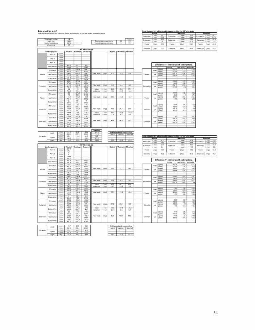
x (mm) 45 x (mm) 36,3 x (mm) 40,1y (mm) -32,8 y (mm) -21,6 y (mm) -17,5
1.2 Position x (mm) -44,5 x (mm) -52,9 x (mm) -41,61805 60 0F5 y (mm) 4 y (mm) -3,6 y (mm) 11,7887,4 937,4 0 0F3
82
Neutral Maximum Slouched Neutral Maximum Slouchedx (mm)y (mm)x (mm)y (mm)x (mm)y (mm)x (mm) 466,8 492,2 452y (mm) 240,9 231,1 224,2 neutral maximum slouchedx (mm) -260,7 -289,4 -264,1 x (mm) -114,2 -111,2 -115,4y (mm) 655,9 641,9 635,5 y(mm) -116,6 -127,8 -85,3x (mm) -146,5 -178,2 -148,7 Head angle (deg) 17,7 15,6 17,6 x (mm) -201,8 -196,1 -202,4y (mm) 772,5 769,7 720,8 y(mm) -144,6 -151,5 -112,9x (mm) -58,9 -93,3 -61,7y (mm) 800,5 793,4 748,4x (mm) -239,1 -279,9 -257,1 x (mm) -159,2 -147,5 -155,5y (mm) 670,3 651,4 638,4 y(mm) -83,8 -106,2 -67,8x (mm) -79,9 -132,4 -101,6 Head angle (deg) 16,6 16,3 14,8 x (mm) -247,3 -235,9 -241y (mm) 754,1 757,6 706,2 y(mm) -110,1 -132 -90,4x (mm) 8,2 -44 -16,1 global x (mm) 66,6 45,8 47,1y (mm) 780,4 783,4 728,8 protraction y (mm) -18,4 -12,1 -14,6x (mm) -233 -276,9 -246,1 x (mm) -180,1 -162,1 -185,3y (mm) 678 655,3 643,8 y(mm) -56,9 -98 -27,4x (mm) -52,9 -114,8 -60,8 Head angle (deg) -35,9 -16,1 -43,7 x (mm) -245,1 -237,8 -242,1y (mm) 734,9 753,3 671,2 y(mm) -9,9 -76,2 26,9x (mm) 12,1 -39,1 -4y (mm) 687,9 731,5 616,9x (mm) -269,3 -296 -270,3 x (mm) -69,7 -58,3 -73,8y (mm) 650,6 637,1 633,3 y(mm) -120,6 -124,2 -97x (mm) -199,6 -237,7 -196,5 Head angle (deg) 23,9 25,6 23,9 x (mm) -151,5 -141 -155y (mm) 771,2 761,3 730,3 y(mm) -156,9 -163,9 -132,9x (mm) -117,8 -155 -115,3 global x (mm) -53,1 -59,5 -47,8y (mm) 807,5 801 766,2 retraction y (mm) -1,3 -8,4 9,5x (mm) -277,4 -301,8 -278,2 x (mm) -52 -32,6 -69,2y (mm) 638,9 628,1 628,4 y(mm) -107,2 -102,8 -86,9x (mm) -225,4 -269,2 -209 Head angle (deg) 90,4 98,9 73,1 x (mm) -51,3 -17,4 -97y (mm) 746,1 730,9 715,3 y(mm) -207,2 -199,7 -178,5x (mm) -226,1 -284,4 -181,2y (mm) 846,1 827,8 806,9
Standingx (mm) -14,2 57,1 -33,4 564,8y (mm) 252,2 275,7 236,3 744,9 neutral maximum slouchedx (mm) 63,3 114,2 56,2 540y (mm) 156,6 171,5 132,5 612,6
Angle deg. -51,0 -61,3 -49,2 -100,6 -49,6 -39,3 -51,4 x (mm) 42,1 x (mm) 40,4 x (mm) 35,6y (mm) -29,9 y (mm) -16,8 y (mm) -22,2x (mm) -31,6 x (mm) -46,4 x (mm) -44,3
Neutral Maximum Slouched Neutral Maximum Slouched y (mm) 6,4 y (mm) -7,6 y (mm) 8,8x (mm) 297,4y (mm) 39,1x (mm) 0y (mm) 0x (mm) -271,5y (mm) 531,6x (mm) 461,7 483,9 443,2y (mm) 231,4 259,6 244,7 neutral maximum slouchedx (mm) -270 -298,7 -263,7 x (mm) -117,1 -100,1 -123,1y (mm) 661,3 637,9 639,3 y(mm) -116,8 -130,2 -83,5x (mm) -152,9 -198,6 -140,6 Head angle (deg) 14,7 17,7 18,9 x (mm) -203,3 -187,7 -206,8y (mm) 778,1 768,1 722,8 y(mm) -139,4 -158,1 -112,1x (mm) -66,7 -111 -56,9y (mm) 800,7 796 751,4x (mm) -249,3 -290,4 -253,7 x (mm) -159,2 -140,5 -158,7y (mm) 674,5 644,4 642,5 y(mm) -86,9 -113,4 -61,3x (mm) -90,1 -149,9 -95 Head angle (deg) 13,4 18,3 16,2 x (mm) -246,8 -229,2 -243,7y (mm) 761,4 757,8 703,8 y(mm) -107,7 -142,7 -86x (mm) -2,5 -61,2 -10 global x (mm) 62,8 48,7 45,6y (mm) 782,2 787,1 728,5 protraction y (mm) -16,7 -10,3 -19x (mm) -240,9 -289,2 -243,2 x (mm) -186 -156,9 -188,4y (mm) 683,4 648,7 646,8 y(mm) -59,2 -105,4 -22,6x (mm) -54,9 -132,3 -54,8 Head angle (deg) -35,1 -13,5 -45,4 x (mm) -248,9 -236,5 -242,9y (mm) 742,6 754,1 669,4 y(mm) -15 -86,3 32,6x (mm) 8 -52,7 -0,3y (mm) 698,4 735 614,2x (mm) -281,2 -305,1 -266,2 x (mm) -85,5 -53,7 -78,8y (mm) 657,7 636,2 638,6 y(mm) -123,2 -122,6 -92,3x (mm) -195,7 -251,4 -187,4 Head angle (deg) 17,2 27,3 16,7 x (mm) -168,9 -135 -169y (mm) 780,9 758,8 730,9 y(mm) -149 -164,6 -119,4x (mm) -112,3 -170,1 -97,2 global x (mm) -42,8 -52,8 -46,8y (mm) 806,7 800,8 758 retraction y (mm) 2,8 -9,3 8,1x (mm) -287 -311 -277,5 x (mm) -47,6 -25,3 -84,8y (mm) 645,6 628,4 631,1 y(mm) -106,7 -98,8 -86,6x (mm) -239,4 -285,7 -192,7 Head angle (deg) 86,7 102,3 68,2 x (mm) -53,3 -3,7 -119,6y (mm) 752,3 727,2 717,7 y(mm) -205,6 -197,8 -173,8x (mm) -233,7 -307,3 -157,9y (mm) 851,2 826,2 804,9
x (mm) -19,7 53,8 -59,1y (mm) 261,2 258,4 212,7 neutral maximum slouchedx (mm) 55,6 95,8 38,3y (mm) 151,7 158,7 132,9
Angle deg. -55,5 -67,2 -39,3 -45,1 -33,5 -61,3
Pelvis rotation from standing
(deg) 49,4
Flexion (deg) -64,2
(deg) 84,6 Extension
-49,8 Flexion (deg) -31,2
72,0 Extension
(deg)
-61,3
55,5
Head displacement with respect to neutral position for 145° knee angle
Extension
(deg)
(deg)
-53,6
72,7
(deg)
(deg)
-31,7
83,3
Retraction:
Extension
Retraction:
Head displacement with respect to neutral position for 100° knee angle
Flexion Flexion Flexion (deg)
Maximum Slouched
Protraction: Protraction: Protraction:
Retraction
Extension
Difference T1-marker and head markers.
Neutral Maximum
Extension
Neutral
Protraction
Protraction:
100° knee angle
Volunteer numberHeight (mm)
Seated height (mm)Max lumbar support (mm):
Vertical displacement (mm):
Extension
Data sheet for task 1Measurements of protraction, retraction, flexion, and extension of the head related to seated postures
Extension
Retraction:
Flexion
Neutral
Protraction
Flexion
Retraction
Pelvis rotation from standing
head
eye
eye
eye
head
Flexion
(deg)
head
eye
head
(deg)
eye
head
head
eye
eye
T1 marker
Weight (kg)
Neutral
Eye position
Lumbar posture:
Knee marker
Point 3
Point 2
Retraction: Retraction:
Difference T1-marker and head markers.
Neutral
Retraction:
Slouched
head
eye
head
Head marker
head
eye
145° knee angle
T1 marker
Head marker
Head marker
T1 marker
head
eye
Lumbar posture:
Head marker
T1 marker
Head marker
Eye position
Head marker
T1 marker
Extension
Retraction
Eye position
Point 1
Eye position
Protraction
Flexion
Eye position
Extension
Eye position
Eye position
Eye position
Eye position
Protraction
T1 marker
T1 marker
Point 1
Point 2
Point 3
Knee marker
Flexion
Retraction
Eye position
Neutral
T1 marker
Head marker
Head marker
T1 marker
Head marker
T1 marker
Protraction:Protraction:
Hip angle
Hip angle
ASIC
H-point
Head marker
ASIC
H-point
34

x (mm) 43,8 x (mm) 41,9 x (mm) 57,8y (mm) -27,1 y (mm) -13,7 y (mm) -22,3
1.3 Position x (mm) -37,3 x (mm) -34,3 x (mm) -34,61800 75 mm 0F5 y (mm) 4,6 y (mm) -6,9 y (mm) 2,9870 920 0 mm 0F383
Neutral Maximum Slouched Neutral Maximum Slouchedx (mm) 229,2y (mm) 32,5x (mm) 0 0 0y (mm) 0 0 0x (mm) -299,7y (mm) 506,3x (mm) 510,5 517,9 492y (mm) 212,5 238 218,4 neutral maximum slouchedx (mm) -319,2 -339,2 -317 x (mm) -131,5 -113,5 -116,9y (mm) 619 605,6 612,6 y(mm) -124,1 -137,3 -85,4x (mm) -187,7 -225,7 -200,1 Head angle (deg) 21,8 23,2 24,4 x (mm) -214,7 -197,9 -198,4y (mm) 743,1 742,9 698 y(mm) -157,4 -173,5 -122,3x (mm) -104,5 -141,3 -118,6y (mm) 776,4 779,1 734,9x (mm) -308,2 -334,8 -309,5 x (mm) -175,3 -155,4 -174,7y (mm) 631,5 610,6 614 y(mm) -97 -123,6 -63,1x (mm) -132,9 -179,4 -134,8 Head angle (deg) 20,9 23,4 18,5 x (mm) -259,1 -238,8 -260,7y (mm) 728,5 734,2 677,1 y(mm) -129 -159,7 -91,8x (mm) -49,1 -96 -48,8 global x (mm) 54,8 46,3 65,3y (mm) 760,5 770,3 705,8 protraction y (mm) -14,6 -8,7 -20,9x (mm) -305,9 -330,2 -302,9 x (mm) -190,3 -164,8 -195,6y (mm) 638,9 618,8 620,8 y(mm) -76,1 -108,9 -35,9x (mm) -115,6 -165,4 -107,3 Head angle (deg) -24,2 -9,5 -37,1 x (mm) -259,2 -244,4 -256,7y (mm) 715 727,7 656,7 y(mm) -45,1 -95,6 10,3x (mm) -46,7 -85,8 -46,2y (mm) 684 714,4 610,5x (mm) -326,8 -342,9 -327,1 x (mm) -94,2 -79,2 -82,3y (mm) 614,9 606,3 611,1 y(mm) -128,7 -130,4 -88,3x (mm) -232,6 -263,7 -244,8 Head angle (deg) 23,3 26,2 26,9 x (mm) -174,1 -162,7 -163,6y (mm) 743,6 736,7 699,4 y(mm) -163,1 -171,4 -129,6x (mm) -152,7 -180,2 -163,5 global x (mm) -44,9 -38 -44,7y (mm) 778 777,7 740,7 retraction y (mm) 0,5 -6,2 1,4x (mm) -330,4 -347,5 -331,9 x (mm) -59,3 -41,1 -89,1y (mm) 601,6 598,7 607,3 y(mm) -115,2 -107,4 -84,9x (mm) -271,1 -306,4 -242,8 Head angle (deg) 99,6 103,4 79,2 x (mm) -43,1 -18,1 -106,4y (mm) 716,8 706,1 692,2 y(mm) -211 -204,2 -176x (mm) -287,3 -329,4 -225,5y (mm) 812,6 802,9 783,3
Standingx (mm)y (mm)x (mm)y (mm)
Angle deg. #DIV/0! #DIV/0! #DIV/0! #DIV/0! x (mm) 48,1 x (mm) 36,7 x (mm) 52,6y (mm) -27,4 y (mm) -15,1 y (mm) -19,4x (mm) -30 x (mm) -38 x (mm) -32,4
Neutral Maximum Slouched Neutral Maximum Slouched y (mm) 1 y (mm) -7,1 y (mm) -0,6x (mm)y (mm)x (mm) 0 0 0y (mm) 0 0 0x (mm)y (mm)x (mm) 490,1 507,8 473,1y (mm) 250,5 264,2 248,9 neutral maximum slouchedx (mm) -320,9 -339,8 -324,5 x (mm) -124,3 -119,1 -117,6y (mm) 616,9 606,2 601,5 y(mm) -126,1 -137,7 -92,4x (mm) -196,6 -220,7 -206,9 Head angle (deg) 22,6 21,5 23,3 x (mm) -207,7 -205,9 -201,9y (mm) 743 743,9 693,9 y(mm) -160,9 -171,9 -128,7x (mm) -113,2 -133,9 -122,6y (mm) 777,8 778,1 730,2x (mm) -310,6 -335,9 -320,7 x (mm) -172,4 -155,8 -170,2y (mm) 628,8 611,1 602,1 y(mm) -98,7 -122,6 -73x (mm) -138,2 -180,1 -150,5 Head angle (deg) 23,2 23,7 20,9 x (mm) -253,8 -239,5 -254,6y (mm) 727,5 733,7 675,1 y(mm) -133,6 -159,3 -105,2x (mm) -56,8 -96,4 -66,1 global x (mm) 58,4 40,6 56,4y (mm) 762,4 770,4 707,3 protraction y (mm) -15,5 -10,2 -18,8x (mm) -300,7 -331,4 -316 x (mm) -191,6 -165,8 -176,4y (mm) 641,1 620,2 605,6 y(mm) -68,2 -109,9 -66x (mm) -109,1 -165,6 -139,6 Head angle (deg) -28,1 -12,5 -29,3 x (mm) -259,7 -244,5 -249,2y (mm) 709,3 730,1 671,6 y(mm) -31,8 -92,4 -25,2x (mm) -41 -86,9 -66,8y (mm) 672,9 712,6 630,8x (mm) -327,4 -345,2 -326,6 x (mm) -94,3 -81,1 -85,2y (mm) 612,9 607 601,3 y(mm) -127,1 -130,6 -91,8x (mm) -233,1 -264,1 -241,4 Head angle (deg) 23,2 23,2 23,0 x (mm) -173,1 -163,4 -167,5y (mm) 740 737,6 693,1 y(mm) -160,8 -165,9 -126,7x (mm) -154,3 -181,8 -159,1 global x (mm) -36,5 -43,4 -34,5y (mm) 773,7 772,9 728 retraction y (mm) -3 -6,3 -0,8x (mm) -329 -344 -329,8 x (mm) -64,9 -20,2 -79,8y (mm) 601,2 598,6595 y(mm) -118,4 -102,2 -83,3x (mm) -264,1 -323,8 -250 Head angle (deg) 96,5 108,4 78,7 x (mm) -54,3 10,9 -98,5y (mm) 719,6 697,2 681,9 y(mm) -211,4 -195,5 -176,8x (mm) -274,7 -354,9 -231,3y (mm) 812,6 790,5 775,4
x (mm)y (mm)x (mm)y (mm)
Angle deg. #DIV/0! #DIV/0! #DIV/0!
Protraction:Protraction:Protraction:
Hip angle
Hip angle
ASIC
H-point
Head marker
ASIC
H-point
Point 1
Point 2
Flexion
Neutral
T1 marker
Head marker
Point 3
Knee marker
Eye position
Retraction
Extension
Eye position
Eye position
Eye position
Eye position
Protraction
T1 marker
Head marker
T1 marker
Extension
Eye position
Protraction
Retraction
Eye position
Flexion
Eye position
Head marker
T1 marker
Lumbar posture:
Knee marker
Point 3
Point 2
Point 1
Head marker
T1 marker
Head marker
Neutral
Eye position
Lumbar posture:
Head marker
T1 marker
Head marker
Eye position
T1 marker
T1 marker
head
Extension
Neutral
Protraction
Retraction:
Flexion
Head displacement with respect to neutral position for 145° knee angle
Neutral
Retraction:
Slouched
head
eye
head
head
eye
eye
Weight (kg)
Retraction: Retraction:
Difference T1-marker and head markers.
145° knee angle
T1 marker
Head marker
Head marker
T1 marker
head
head
eye
head
eye
head
eye
head
eye
Data sheet for task 1Measurements of protraction, retraction, flexion, and extension of the head related to seated postures
Extension Extension100° knee angle
Volunteer numberHeight (mm)
Seated height (mm)Max lumbar support (mm):
Vertical displacement (mm):
Neutral
Protraction
Flexion
Retraction
Retraction
Extension
Difference T1-marker and head markers.
Neutral Maximum
Flexion
Extension
head
eye
Head displacement with respect to neutral position for 100° knee angle
Flexion Flexion Flexion (deg)
Maximum Slouched
Protraction: Protraction: Protraction:
Retraction:
(deg)
-61,5
54,9
Retraction:
(deg)
-32,7
80,2 Extension
(deg)
(deg) 86,9
(deg)
(deg)
-46,0
77,8
eye
(deg)
73,9 Extension
eye
(deg)
-50,8 Flexion (deg) -34,0
(deg) 55,4
Flexion (deg) -52,6
Extension
35
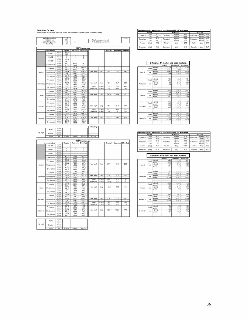
x (mm) 55,1 x (mm) 43,3 x (mm) 55,5y (mm) -30 y (mm) -21,6 y (mm) -18,1
1.4 Position x (mm) -31,8 x (mm) -39,8 x (mm) -41,61800 y (mm) 2,2 y (mm) -3,4 y (mm) 1,4870 92083
Neutral Maximum Slouched Neutral Maximum Slouchedx (mm) 299,2y (mm) 32,7x (mm) 0 0 0y (mm) 0 0 0x (mm) -301,8y (mm) 506,8x (mm) 486,4 521,3 475,3y (mm) 211,2 218,4 223,7 neutral maximum slouchedx (mm) -322 -340,6 -326,3 x (mm) -123,6 -119,3 -117,9y (mm) 630,3 612,1 598,7 y(mm) -121,7 -134 -93x (mm) -198,4 -221,3 -208,4 Head angle (deg) 22,9 23,2 24,0 x (mm) -204,9 -200,6 -201,6y (mm) 752 746,1 691,7 y(mm) -156 -168,8 -130,3x (mm) -117,1 -140 -124,7y (mm) 786,3 780,9 729x (mm) -306,9 -331,7 -320,6 x (mm) -178,7 -162,6 -173,4y (mm) 645,3 622,5 600 y(mm) -91,7 -112,4 -74,9x (mm) -128,2 -169,1 -147,2 Head angle (deg) 19,7 21,7 23,0 x (mm) -262 -245,5 -256,5y (mm) 737 734,9 674,9 y(mm) -121,5 -145,4 -110,1x (mm) -44,9 -86,2 -64,1 global x (mm) 70,2 52,2 61,2y (mm) 766,8 767,9 710,1 protraction y (mm) -15 -11,2 -16,8x (mm) -309 -328,7 -310,5 x (mm) -190,4 -166,6 -201,1y (mm) 648,2 625,1 605,8 y(mm) -79,4 -106,9 -36,8x (mm) -118,6 -162,1 -109,4 Head angle (deg) -26,0 -10,8 -40,7 x (mm) -258,6 -243,4 -258,6y (mm) 727,6 732 642,6 y(mm) -46,1 -92,2 12,6x (mm) -50,4 -85,3 -51,9y (mm) 694,3 717,3 593,2x (mm) -327,3 -342 -328,9 x (mm) -91,8 -79,5 -76,3y (mm) 625,2 608,5 595,1 y(mm) -123,9 -130,6 -94,4x (mm) -235,5 -262,5 -252,6 Head angle (deg) 25,2 25,4 30,1 x (mm) -170,5 -158,6 -153,7y (mm) 749,1 739,1 689,5 y(mm) -160,9 -168,2 -139,2x (mm) -156,8 -183,4 -175,2 global x (mm) -37,1 -41,2 -44,2y (mm) 786,1 776,7 734,3 retraction y (mm) -2,9 -7 -2,2x (mm) -331,6 -345,4 -334,4 x (mm) -77,6 -32,5 -79,5y (mm) 612,7 601,2 590,3 y(mm) -123,7 -106,5 -95,4x (mm) -254 -312,9 -254,9 Head angle (deg) 90,2 104,1 77,7 x (mm) -77,3 -9,5 -99,1y (mm) 736,4 707,7 685,7 y(mm) -214,6 -198,3 -185,6x (mm) -254,3 -335,9 -235,3y (mm) 827,3 799,5 775,9
Standingx (mm)y (mm)x (mm)y (mm)
Angle deg. #DIV/0! #DIV/0! #DIV/0! #DIV/0! x (mm) 50,4 x (mm) 34,4 x (mm) 52,1y (mm) -27,8 y (mm) -11,3 y (mm) -22x (mm) -24,2 x (mm) -52,6 x (mm) -32,5
Neutral Maximum Slouched Neutral Maximum Slouched y (mm) -1,2 y (mm) -3,6 y (mm) 1,1x (mm)y (mm)x (mm) 0 0 0y (mm) 0 0 0x (mm)y (mm)x (mm) 470,4 510,2 463,5y (mm) 234,8 254,3 239,1 neutral maximum slouchedx (mm) -330,3 -341,2 -326,6 x (mm) -122,6 -119,2 -121,1y (mm) 628,8 608,9 598,8 y(mm) -125,5 -131,7 -93,4x (mm) -207,7 -222 -205,5 Head angle (deg) 21,7 22,1 23,7 x (mm) -204,7 -204,3 -202,8y (mm) 754,3 740,6 692,2 y(mm) -158,1 -166,2 -129,2x (mm) -125,6 -136,9 -123,8y (mm) 786,9 775,1 728x (mm) -315,9 -334,5 -320,7 x (mm) -173 -153,6 -173,2y (mm) 642,8 615,1 601,7 y(mm) -97,7 -120,4 -71,4x (mm) -142,9 -180,9 -147,5 Head angle (deg) 20,6 21,6 20,1 x (mm) -257,4 -237,6 -258,3y (mm) 740,5 735,5 673,1 y(mm) -129,4 -153,7 -102,5x (mm) -58,5 -96,9 -62,4 global x (mm) 64,8 41,1 58y (mm) 772,2 768,8 704,2 protraction y (mm) -13,8 -5,1 -19,1x (mm) -310,4 -330,9 -313,1 x (mm) -188,6 -163,1 -196y (mm) 648,7 620,4 607 y(mm) -77,5 -111,7 -43,3x (mm) -121,8 -167,8 -117,1 Head angle (deg) -23,6 -11,9 -34,9 x (mm) -258,8 -240,6 -258,9y (mm) 726,2 732,1 650,3 y(mm) -46,8 -95,3 0,6x (mm) -51,6 -90,3 -54,2y (mm) 695,5 715,7 606,4x (mm) -332,1 -345,3 -328,7 x (mm) -98,4 -66,6 -88,6y (mm) 627,7 606 599 y(mm) -124,3 -128,1 -94,5x (mm) -233,7 -278,7 -240,1 Head angle (deg) 23,0 27,6 22,3 x (mm) -181 -146,7 -171,6y (mm) 752 734,1 693,5 y(mm) -159,4 -169,9 -128,5x (mm) -151,1 -198,6 -157,1 global x (mm) -26 -56,7 -34,6y (mm) 787,1 775,9 727,5 retraction y (mm) -2,3 -6,5 1,3x (mm) -337,9 -347 -335 x (mm) -73,5 -25,1 -76,9y (mm) 613,6 595,8 593,9 y(mm) -117 -104,1 -83,8x (mm) -264,4 -321,9 -258,1 Head angle (deg) 90,2 105,7 77,8 x (mm) -73,2 1 -96,9y (mm) 730,6 699,9 677,7 y(mm) -213,1 -197,1 -176x (mm) -264,7 -348 -238,1y (mm) 826,7 792,9 769,9
x (mm)y (mm)x (mm)y (mm)
Angle deg. #DIV/0! #DIV/0! #DIV/0!
Protraction:Protraction:Protraction:
Hip angle
Hip angle
ASIC
H-point
Head marker
ASIC
H-point
Point 1
Point 2
Flexion
Neutral
T1 marker
Head marker
Point 3
Knee marker
Eye position
Retraction
Extension
Eye position
Eye position
Eye position
Eye position
Protraction
T1 marker
Head marker
T1 marker
Extension
Eye position
Protraction
Retraction
Eye position
Flexion
Eye position
Head marker
T1 marker
Lumbar posture:
Knee marker
Point 3
Point 2
Point 1
Head marker
T1 marker
Head marker
Neutral
Eye position
Lumbar posture:
Head marker
T1 marker
Head marker
Eye position
T1 marker
T1 marker
head
Extension
Neutral
Protraction
Retraction:
Flexion
Head displacement with respect to neutral position for 145° knee angle
Retraction:
Slouched
head
eye
head
head
eye
eye
Weight (kg)
Retraction: Retraction:
Difference T1-marker and head markers.
145° knee angle
T1 marker
Head marker
Head marker
T1 marker
head
Vertical displacement (mm):
eye
eye
(deg)
(deg)
head
eye
eye
head
eye
head
Data sheet for task 1Measurements of protraction, retraction, flexion, and extension of the head related to seated postures
Extension Extension100° knee angle
Volunteer numberHeight (mm)
Seated height (mm)Max lumbar support (mm):
Head displacement with respect to neutral position for 100° knee angle
Neutral
Protraction
Flexion
Retraction
Retraction
Extension
Difference T1-marker and head markers.
Neutral Maximum
Flexion
Extension
head
eye
Flexion Flexion Flexion (deg)(deg)
Maximum Slouched
Protraction: Protraction: Protraction:
Neutral
Retraction:
(deg)
-64,7
53,7
Retraction:
(deg)
-34,0
80,9 Extension
(deg)
(deg) 83,6
(deg)
-48,9
67,3
head
68,5 Extension
eye
-45,3 Flexion (deg) -34,0
(deg) 54,1
Flexion (deg) -58,6
Extension
36

x (mm) 48,9 x (mm) 35,3 x (mm) 52y (mm) -27,4 y (mm) -17,4 y (mm) -16,9
1.5 Position x (mm) -36,1 x (mm) -38,8 x (mm) -281800 y (mm) 1,5 y (mm) 0,6 y (mm) 1,6870 92083
Neutral Maximum Slouched Neutral Maximum Slouchedx (mm) 299,2y (mm) 32,6x (mm) 0 0 0y (mm) 0 0 0x (mm) -301,4y (mm) 507x (mm) 499,3 516,4 500,4y (mm) 216,6 216,9 229,4 neutral maximum slouchedx (mm) -323,6 -336,9 -323,8 x (mm) -124,9 -123,5 -115,2y (mm) 624,6 614,6 590,5 y(mm) -123,8 -132,5 -89,5x (mm) -198,7 -213,4 -208,6 Head angle (deg) 21,6 23,5 22,0 x (mm) -207,1 -203,4 -195,5y (mm) 748,4 747,1 680 y(mm) -156,3 -167,2 -122x (mm) -116,5 -133,5 -128,3y (mm) 780,9 781,8 712,5x (mm) -310,6 -329,7 -320,1 x (mm) -173,8 -158,8 -167,2y (mm) 637 623,9 593,3 y(mm) -96,4 -115,1 -72,6x (mm) -136,8 -170,9 -152,9 Head angle (deg) 18,7 20,8 20,4 x (mm) -257,8 -242,9 -248,8y (mm) 733,4 739 665,9 y(mm) -124,8 -147 -102,9x (mm) -52,8 -86,8 -71,3 global x (mm) 61,9 42,5 55,7y (mm) 761,8 770,9 696,2 protraction y (mm) -15 -8,1 -14,1x (mm) -307,5 -327,1 -317,6 x (mm) -186,1 -164,8 -190,5y (mm) 644,1 627,8 592,9 y(mm) -76,6 -108,1 -46,4x (mm) -121,4 -162,3 -127,1 Head angle (deg) -26,0 -11,2 -33,2 x (mm) -257,1 -239,8 -256,9y (mm) 720,7 735,9 639,3 y(mm) -42 -93,2 -3x (mm) -50,4 -87,3 -60,7y (mm) 686,1 721 595,9x (mm) -332,8 -342,8 -327,9 x (mm) -88,8 -84,7 -87,2y (mm) 619,6 610,1 588,9 y(mm) -125,3 -133,1 -91,1x (mm) -244 -258,1 -240,7 Head angle (deg) 23,5 25,7 24,7 x (mm) -171,2 -165 -165,8y (mm) 744,9 743,2 680 y(mm) -161,1 -171,8 -127,3x (mm) -161,6 -177,8 -162,1 global x (mm) -45,3 -44,7 -32,1y (mm) 780,7 781,9 716,2 retraction y (mm) -3,5 -3,9 0x (mm) -338,8 -343,8 -330,3 x (mm) -58,9 -40,8 -79,6y (mm) 602,6 601,2 584,9 y(mm) -112,2 -111,4 -88,2x (mm) -279,9 -303 -250,7 Head angle (deg) 95,8 100,8 71,8 x (mm) -48,6 -22,7 -108,9y (mm) 714,8 712,6 673,1 y(mm) -213,3 -205,9 -177,3x (mm) -290,2 -321,1 -221,4y (mm) 815,9 807,1 762,2
Standingx (mm)y (mm)x (mm)y (mm)
Angle deg. #DIV/0! #DIV/0! #DIV/0! #DIV/0! x (mm) 43,4 x (mm) 41,3 x (mm) 50,6y (mm) -34 y (mm) -23,2 y (mm) -17,1x (mm) -33,8 x (mm) -26,8 x (mm) -33
Neutral Maximum Slouched Neutral Maximum Slouched y (mm) 3,6 y (mm) -5,6 y (mm) 1,3x (mm)y (mm)x (mm) 0 0 0y (mm) 0 0 0x (mm)y (mm)x (mm) 486,5 574,3 484,6y (mm) 235,4 208,7 249,3 neutral maximum slouchedx (mm) -317 -335 -323,3 x (mm) -130,1 -119,1 -115,1y (mm) 627,2 613,2 589,8 y(mm) -117,6 -135 -93,8x (mm) -186,9 -215,9 -208,2 Head angle (deg) 21,7 23,0 20,0 x (mm) -215,1 -202,1 -199,4y (mm) 744,8 748,2 683,6 y(mm) -151,4 -170,2 -124,4x (mm) -101,9 -132,9 -123,9y (mm) 778,6 783,4 714,2x (mm) -299,6 -326,2 -321,5 x (mm) -173,5 -160,4 -165,7y (mm) 641,8 624,4 591,4 y(mm) -83,6 -111,8 -76,7x (mm) -126,1 -165,8 -155,8 Head angle (deg) 18,8 22,1 21,6 x (mm) -261,5 -245,2 -249,2y (mm) 725,4 736,2 668,1 y(mm) -113,6 -146,3 -109,8x (mm) -38,1 -81 -72,3 global x (mm) 60,8 50,1 52,4y (mm) 755,4 770,7 701,2 protraction y (mm) -19,4 -12 -15,5x (mm) -295,6 -321,1 -317,8 x (mm) -186,7 -171,1 -194,5y (mm) 648,2 629 593,8 y(mm) -64,5 -101,2 -49,1x (mm) -108,9 -150 -123,3 Head angle (deg) -27,2 -11,9 -32,8 x (mm) -256,7 -248,1 -259,4y (mm) 712,7 730,2 642,9 y(mm) -28,6 -85 -7,3x (mm) -38,9 -73 -58,4y (mm) 676,8 714 601,1x (mm) -321,9 -339 -328 x (mm) -96,3 -92,3 -82,1y (mm) 621,3 611,1 588,5 y(mm) -121,2 -129,4 -95,1x (mm) -225,6 -246,7 -245,9 Head angle (deg) 21,8 24,6 23,6 x (mm) -180,4 -173,1 -163,3y (mm) 742,5 740,5 683,6 y(mm) -154,9 -166,4 -130,6x (mm) -141,5 -165,9 -164,7 global x (mm) -38,7 -30,8 -37,7y (mm) 776,2 777,5 719,1 retraction y (mm) -2,3 -7,7 0x (mm) -322,8 -340,1 -330,7 x (mm) -78,3 -51,5 -71,6y (mm) 608,9 598,9 584,2 y(mm) -114,8 -114,7 -89,8x (mm) -244,5 -288,6 -259,1 Head angle (deg) 87,5 100,4 75,6 x (mm) -82,5 -33,5 -95y (mm) 723,7 713,6 674 y(mm) -212,1 -212,3 -181,1x (mm) -240,3 -306,6 -235,7y (mm) 821 811,2 765,3
x (mm)y (mm)x (mm)y (mm)
Angle deg. #DIV/0! #DIV/0! #DIV/0!
(deg) 55,7
Flexion (deg) -52,7
Extension
-48,8 Flexion (deg) -34,9
65,8 Extension
eye
(deg) 77,5
(deg)
(deg)
-47,6
74,2
Retraction:
(deg)
-55,2
49,8
Retraction:
(deg)
-34,7
77,4 Extension
(deg)
Head displacement with respect to neutral position for 100° knee angle
Flexion Flexion Flexion (deg)
Maximum Slouched
Protraction: Protraction: Protraction:
Retraction
Extension
Difference T1-marker and head markers.
Neutral Maximum
Flexion
Extension
head
eye
Neutral
Protraction
Flexion
Retraction
Data sheet for task 1Measurements of protraction, retraction, flexion, and extension of the head related to seated postures
Extension Extension100° knee angle
Volunteer numberHeight (mm)
Seated height (mm)Max lumbar support (mm):
Vertical displacement (mm):
eye
head
eye
head
eye
eye
(deg)
(deg)
head
eye
head
Weight (kg)
Retraction: Retraction:
Difference T1-marker and head markers.
145° knee angle
T1 marker
Head marker
Head marker
T1 marker
head
Neutral
Retraction:
Slouched
head
eye
head
head
eye
eye
T1 marker
T1 marker
head
Extension
Neutral
Protraction
Retraction:
Flexion
Head displacement with respect to neutral position for 145° knee angle
Head marker
T1 marker
Head marker
Neutral
Eye position
Lumbar posture:
Head marker
T1 marker
Head marker
Eye position
Lumbar posture:
Knee marker
Point 3
Point 2
Point 1
Extension
Eye position
Protraction
Retraction
Eye position
Flexion
Eye position
Head marker
T1 marker
Retraction
Extension
Eye position
Eye position
Eye position
Eye position
Protraction
T1 marker
Head marker
T1 marker
Point 1
Point 2
Flexion
Neutral
T1 marker
Head marker
Point 3
Knee marker
Eye position
Protraction:Protraction:Protraction:
Hip angle
Hip angle
ASIC
H-point
Head marker
ASIC
H-point
37
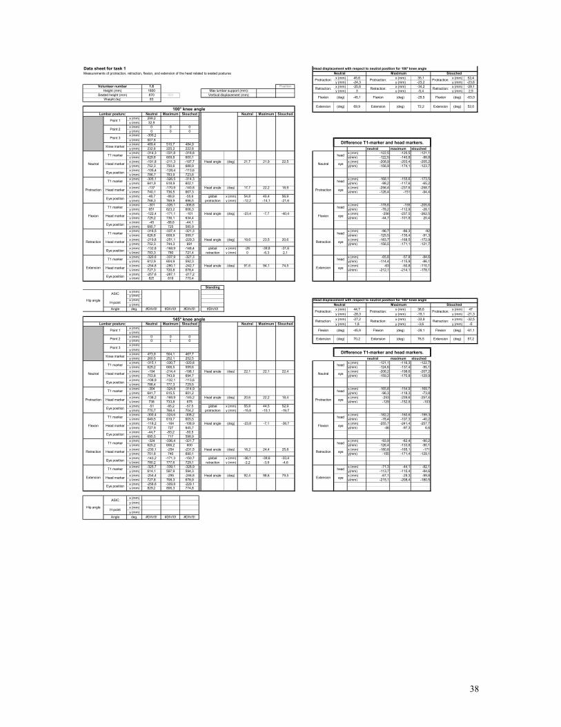
x (mm) 45,6 x (mm) 35,1 x (mm) 52,4y (mm) -24,3 y (mm) -23,2 y (mm) -23,6
1.6 Position x (mm) -25,8 x (mm) -34,2 x (mm) -29,11800 y (mm) 3 y (mm) -5,4 y (mm) 2,5870 92083
Neutral Maximum Slouched Neutral Maximum Slouchedx (mm) 299,2y (mm) 32,9x (mm) 0 0 0y (mm) 0 0 0x (mm) -300,2y (mm) 507,6x (mm) 489,4 510,7 484,9y (mm) 232,6 225,2 222,8 neutral maximum slouchedx (mm) -314,3 -331,8 -318,8 x (mm) -122,5 -120,5 -121,1y (mm) 629,8 609,8 600,1 y(mm) -122,5 -140,8 -88,8x (mm) -191,8 -211,3 -197,7 Head angle (deg) 21,7 21,9 22,5 x (mm) -208,9 -203,4 -205,2y (mm) 752,3 750,6 688,9 y(mm) -156,9 -174,1 -123,7x (mm) -105,4 -128,4 -113,6y (mm) 786,7 783,9 723,8x (mm) -305,1 -326,5 -314,3 x (mm) -168,1 -155,6 -173,5y (mm) 641,9 618,9 602,1 y(mm) -98,2 -117,6 -65,2x (mm) -137 -170,9 -140,8 Head angle (deg) 17,7 22,2 18,9 x (mm) -256,4 -237,6 -258,7y (mm) 740,1 736,5 667,3 y(mm) -126,4 -151 -94,4x (mm) -48,7 -88,9 -55,6 global x (mm) 54,8 40,4 56,9y (mm) 768,3 769,9 696,5 protraction y (mm) -12,2 -14,1 -21,6x (mm) -301 -326,1 -306,6 x (mm) -178,6 -155 -205,6y (mm) 651 623,2 606,3 y(mm) -78,2 -112,9 -28,1x (mm) -122,4 -171,1 -101 Head angle (deg) -23,4 -7,7 -40,4 x (mm) -256 -237,5 -262,5y (mm) 729,2 736,1 634,4 y(mm) -44,7 -101,8 20,4x (mm) -45 -88,6 -44,1y (mm) 695,7 725 585,9x (mm) -316,5 -337,4 -321,3 x (mm) -96,7 -86,3 -92y (mm) 626,8 608,9 599,7 y(mm) -125,5 -135,4 -91,3x (mm) -219,8 -251,1 -229,3 Head angle (deg) 19,6 23,5 20,6 x (mm) -183,7 -168,5 -172,9y (mm) 752,3 744,3 691 y(mm) -156,5 -171,1 -121,7x (mm) -132,8 -168,9 -148,4 global x (mm) -28 -39,8 -31,6y (mm) 783,3 780 721,4 retraction y (mm) 0 -6,3 2,1x (mm) -320,6 -337,9 -327,3 x (mm) -65,8 -57,8 -84,6y (mm) 612,9 604,9 592,3 y(mm) -114,4 -115,9 -86,1x (mm) -254,8 -280,1 -242,7 Head angle (deg) 91,6 94,1 74,5 x (mm) -63 -50,8 -110,1y (mm) 727,3 720,8 678,4 y(mm) -212,1 -214,1 -178,1x (mm) -257,6 -287,1 -217,2y (mm) 825 819 770,4
Standingx (mm)y (mm)x (mm)y (mm)
Angle deg. #DIV/0! #DIV/0! #DIV/0! #DIV/0! x (mm) 44,7 x (mm) 38,6 x (mm) 47y (mm) -28,3 y (mm) -19,1 y (mm) -21,3x (mm) -27,2 x (mm) -33,9 x (mm) -32,5
Neutral Maximum Slouched Neutral Maximum Slouched y (mm) 1,8 y (mm) -3,6 y (mm) -5x (mm)y (mm)x (mm) 0 0 0y (mm) 0 0 0x (mm)y (mm)x (mm) 473,9 504,1 467,7y (mm) 260,5 252,1 252,5 neutral maximum slouchedx (mm) -315,1 -330,7 -320,8 x (mm) -121,1 -116,3 -122,7y (mm) 629,2 606,5 599,6 y(mm) -124,6 -137,4 -95,1x (mm) -194 -214,4 -198,1 Head angle (deg) 22,1 22,1 22,4 x (mm) -206,2 -198,6 -207,2y (mm) 753,8 743,9 694,7 y(mm) -159,2 -170,8 -129,9x (mm) -108,9 -132,1 -113,6y (mm) 788,4 777,3 729,5x (mm) -304 -324,8 -314,9 x (mm) -165,8 -154,9 -169,7y (mm) 641,7 615,5 601,2 y(mm) -96,3 -118,3 -73,8x (mm) -138,2 -169,9 -145,2 Head angle (deg) 20,6 22,2 18,4 x (mm) -253 -239,6 -257,4y (mm) 738 733,8 675 y(mm) -129 -152,9 -103x (mm) -51 -85,2 -57,5 global x (mm) 55,8 44,5 52,9y (mm) 770,7 768,4 704,2 protraction y (mm) -15,8 -10,1 -19,7x (mm) -300,4 -324,6 -308,2 x (mm) -182,2 -160,6 -199,3y (mm) 649,5 619,7 605,5 y(mm) -78,4 -107,3 -40,2x (mm) -118,2 -164 -108,9 Head angle (deg) -23,8 -7,1 -38,7 x (mm) -255,7 -241,4 -257,7y (mm) 727,9 727 645,7 y(mm) -46 -97,3 6,6x (mm) -44,7 -83,2 -50,5y (mm) 695,5 717 598,9x (mm) -324 -336,4 -321,7 x (mm) -93,9 -82,4 -90,2y (mm) 625,2 606,2 600 y(mm) -126,4 -133,8 -90,1x (mm) -230,1 -254 -231,5 Head angle (deg) 18,2 24,4 25,8 x (mm) -180,8 -165,1 -171y (mm) 751,6 740 690,1 y(mm) -155 -171,4 -129,1x (mm) -143,2 -171,3 -150,7 global x (mm) -36,1 -39,6 -33,4y (mm) 780,2 777,6 729,1 retraction y (mm) -2,2 -3,9 -4,6x (mm) -325,7 -339,1 -328,9 x (mm) -71,3 -44,1 -82,1y (mm) 614,1 597,9 594,3 y(mm) -113,7 -110,4 -84,6x (mm) -254,4 -295 -246,8 Head angle (deg) 92,4 98,6 79,5 x (mm) -67,1 -29,3 -99,8y (mm) 727,8 708,3 678,9 y(mm) -215,1 -208,4 -180,5x (mm) -258,6 -309,8 -229,1y (mm) 829,2 806,3 774,8
x (mm)y (mm)x (mm)y (mm)
Angle deg. #DIV/0! #DIV/0! #DIV/0!
(deg) 57,2
Flexion (deg) -61,1
Extension
-45,9 Flexion (deg) -29,1
70,2 Extension
eye
(deg) 76,5
(deg)
(deg)
-45,1
69,9
Retraction:
(deg)
-63,0
52,0
Retraction:
(deg)
-29,5
72,2 Extension
(deg)
Head displacement with respect to neutral position for 100° knee angle
Flexion Flexion Flexion (deg)
Maximum Slouched
Protraction: Protraction: Protraction:
Retraction
Extension
Difference T1-marker and head markers.
Neutral Maximum
Flexion
Extension
head
eye
Neutral
Protraction
Flexion
Retraction
Data sheet for task 1Measurements of protraction, retraction, flexion, and extension of the head related to seated postures
Extension Extension100° knee angle
Volunteer numberHeight (mm)
Seated height (mm)Max lumbar support (mm):
Vertical displacement (mm):
eye
head
eye
head
eye
eye
(deg)
(deg)
head
eye
head
Weight (kg)
Retraction: Retraction:
Difference T1-marker and head markers.
145° knee angle
T1 marker
Head marker
Head marker
T1 marker
head
Neutral
Retraction:
Slouched
head
eye
head
head
eye
eye
T1 marker
T1 marker
head
Extension
Neutral
Protraction
Retraction:
Flexion
Head displacement with respect to neutral position for 145° knee angle
Head marker
T1 marker
Head marker
Neutral
Eye position
Lumbar posture:
Head marker
T1 marker
Head marker
Eye position
Lumbar posture:
Knee marker
Point 3
Point 2
Point 1
Extension
Eye position
Protraction
Retraction
Eye position
Flexion
Eye position
Head marker
T1 marker
Retraction
Extension
Eye position
Eye position
Eye position
Eye position
Protraction
T1 marker
Head marker
T1 marker
Point 1
Point 2
Flexion
Neutral
T1 marker
Head marker
Point 3
Knee marker
Eye position
Protraction:Protraction:Protraction:
Hip angle
Hip angle
ASIC
H-point
Head marker
ASIC
H-point
38

x (mm) 54,9 x (mm) 44,7 x (mm) 61,1y (mm) -29,1 y (mm) -21,4 y (mm) -24,2
1.7 Position x (mm) -22,5 x (mm) -30,3 x (mm) -21,51800 y (mm) 4,1 y (mm) -6,5 y (mm) -1,2870 92083
Neutral Maximum Slouched Neutral Maximum Slouchedx (mm)y (mm)x (mm) 0 0 0y (mm) 0 0 0x (mm)y (mm)x (mm) 489,7 501,7 478,6y (mm) 232,4 241,3 231,7 neutral maximum slouchedx (mm) -314,5 -335,6 -322,3 x (mm) -116,9 -111,5 -108,8y (mm) 621,2 607,7 600,4 y(mm) -119,3 -138,4 -90,7x (mm) -197,6 -224,1 -213,5 Head angle (deg) 24,0 22,5 23,3 x (mm) -201,4 -197,5 -191,1y (mm) 740,5 746,1 691,1 y(mm) -156,9 -174,1 -126,2x (mm) -113,1 -138,1 -131,2y (mm) 778,1 781,8 726,6x (mm) -302,5 -330,8 -318,5 x (mm) -171,8 -156,2 -169,9y (mm) 634,2 620,2 601,4 y(mm) -90,2 -117 -66,5x (mm) -130,7 -174,6 -148,6 Head angle (deg) 20,6 23,4 22,0 x (mm) -257,9 -241,4 -255,7y (mm) 724,4 737,2 667,9 y(mm) -122,5 -153,9 -101,2x (mm) -44,6 -89,4 -62,8 global x (mm) 66,9 49,5 64,9y (mm) 756,7 774,1 702,6 protraction y (mm) -16,1 -8,9 -23,2x (mm) -294,6 -328,2 -310,5 x (mm) -191,2 -167,4 -198,4y (mm) 645,8 622,8 605,1 y(mm) -63,6 -110,2 -30,9x (mm) -103,4 -160,8 -112,1 Head angle (deg) -30,2 -10,7 -36,2 x (mm) -258,7 -246,5 -259,7y (mm) 709,4 733 636 y(mm) -24,3 -95,2 13,9x (mm) -35,9 -81,7 -50,8y (mm) 670,1 718 591,2x (mm) -320,9 -339,7 -323,7 x (mm) -94,4 -81,2 -87,3y (mm) 617,7 610 599,1 y(mm) -123,4 -131,9 -89,5x (mm) -226,5 -258,5 -236,4 Head angle (deg) 22,9 23,7 23,8 x (mm) -177,3 -162,6 -169,1y (mm) 741,1 741,9 688,6 y(mm) -158,5 -167,7 -125,5x (mm) -143,6 -177,1 -154,6 global x (mm) -28,9 -34,4 -22,9y (mm) 776,2 777,7 724,6 retraction y (mm) 0,6 -4,2 -2,5x (mm) -326,8 -342,8 -330,6 x (mm) -59 -36,8 -89,1y (mm) 603,6 598,9 594,4 y(mm) -107,4 -105,7 -83,5x (mm) -267,8 -306 -241,5 Head angle (deg) 94,5 102,1 72,1 x (mm) -51,1 -15,8 -118,7y (mm) 711 704,6 677,9 y(mm) -207,6 -203,4 -175,4x (mm) -275,7 -327 -211,9y (mm) 811,2 802,3 769,8
Standingx (mm)y (mm)x (mm)y (mm)
Angle deg. #DIV/0! #DIV/0! #DIV/0! #DIV/0! x (mm) 45,5 x (mm) 39,3 x (mm) 40,3y (mm) -33,9 y (mm) -22,6 y (mm) -33,4x (mm) -25,5 x (mm) -41,6 x (mm) -46,5
Neutral Maximum Slouched Neutral Maximum Slouched y (mm) 3,2 y (mm) -6,1 y (mm) -5,1x (mm) 299,2y (mm) 33,3x (mm) 0 0 0y (mm) 0 0 0x (mm) -300,7y (mm) 507,3x (mm) 467 493,2 456,7y (mm) 249 247,3 238,7 neutral maximum slouchedx (mm) -313,9 -338,8 -321,4 x (mm) -130,4 -118,4 -138,3y (mm) 632 609,3 606,2 y(mm) -121,6 -140,8 -93,6x (mm) -183,5 -220,4 -183,1 Head angle (deg) 21,4 21,3 16,1 x (mm) -213,8 -203,9 -223,6y (mm) 753,6 750,1 699,8 y(mm) -154,3 -174,1 -118,2x (mm) -100,1 -134,9 -97,8y (mm) 786,3 783,4 724,4x (mm) -299,8 -331,2 -313,1 x (mm) -175,9 -157,7 -178,6y (mm) 645,6 621,7 607 y(mm) -87,7 -118,2 -60,2x (mm) -123,9 -173,5 -134,5 Head angle (deg) 18,0 22,1 17,2 x (mm) -260,8 -243,1 -263,8y (mm) 733,3 739,9 667,2 y(mm) -115,3 -152,9 -86,6x (mm) -39 -88,1 -49,3 global x (mm) 59,6 46,9 48,6y (mm) 760,9 774,6 693,6 protraction y (mm) -20,3 -10,2 -32,6x (mm) -298,8 -329,5 -305 x (mm) -190 -171,9 -204,3y (mm) 653,7 627,2 611,2 y(mm) -65,4 -107,2 -24,4x (mm) -108,8 -157,6 -100,7 Head angle (deg) -25,6 -11,0 -42,9 x (mm) -262,4 -248,5 -260,3y (mm) 719,1 734,4 635,6 y(mm) -30,7 -92,3 27,7x (mm) -36,4 -81 -44,7y (mm) 684,4 719,5 583,5x (mm) -321,7 -343,1 -326,2 x (mm) -104,9 -76,8 -91,8y (mm) 628,1 609,9 603,9 y(mm) -124,8 -134,7 -88,5x (mm) -216,8 -266,3 -234,4 Head angle (deg) 19,9 26,4 25,7 x (mm) -189 -156,2 -172,5y (mm) 752,9 744,6 692,4 y(mm) -155,2 -174,1 -127,3x (mm) -132,7 -186,9 -153,7 global x (mm) -33,3 -45,9 -51,3y (mm) 783,3 784 731,2 retraction y (mm) -0,7 -5,5 -7,4x (mm) -327,4 -346,6 -330 x (mm) -64,4 -30,1 -78,5y (mm) 615,7 597,1 597,5 y(mm) -108,4 -107,3 -81x (mm) -263 -316,5 -251,5 Head angle (deg) 92,1 104,0 78,0 x (mm) -60,7 -6,4 -98,9y (mm) 724,1 704,4 678,5 y(mm) -207,8 -202,6 -176,8x (mm) -266,7 -340,2 -231,1y (mm) 823,5 799,7 774,3
x (mm)y (mm)x (mm)y (mm)
Angle deg. #DIV/0! #DIV/0! #DIV/0!
Protraction:Protraction:Protraction:
Hip angle
Hip angle
ASIC
H-point
Head marker
ASIC
H-point
Point 1
Point 2
Flexion
Neutral
T1 marker
Head marker
Point 3
Knee marker
Eye position
Retraction
Extension
Eye position
Eye position
Eye position
Eye position
Protraction
T1 marker
Head marker
T1 marker
Extension
Eye position
Protraction
Retraction
Eye position
Flexion
Eye position
Head marker
T1 marker
Lumbar posture:
Knee marker
Point 3
Point 2
Point 1
Head marker
T1 marker
Head marker
Neutral
Eye position
Lumbar posture:
Head marker
T1 marker
Head marker
Eye position
T1 marker
T1 marker
head
Extension
Neutral
Protraction
Retraction:
Flexion
Head displacement with respect to neutral position for 145° knee angle
Retraction:
Slouched
head
eye
head
head
eye
eye
Weight (kg)
Retraction: Retraction:
Difference T1-marker and head markers.
145° knee angle
T1 marker
Head marker
Head marker
T1 marker
head
Vertical displacement (mm):
eye
eye
(deg)
(deg)
head
eye
eye
head
eye
head
Data sheet for task 1Measurements of protraction, retraction, flexion, and extension of the head related to seated postures
Extension Extension100° knee angle
Volunteer numberHeight (mm)
Seated height (mm)Max lumbar support (mm):
Head displacement with respect to neutral position for 100° knee angle
Neutral
Protraction
Flexion
Retraction
Retraction
Extension
Difference T1-marker and head markers.
Neutral Maximum
Flexion
Extension
head
eye
Flexion Flexion Flexion (deg)(deg)
Maximum Slouched
Protraction: Protraction: Protraction:
Neutral
Retraction:
(deg)
-59,5
48,8
Retraction:
(deg)
-33,3
79,6 Extension
(deg)
(deg) 82,7
(deg)
-54,2
70,5
head
70,7 Extension
eye
-47,0 Flexion (deg) -32,3
(deg) 61,9
Flexion (deg) -59,0
Extension
39

x (mm) 50,3 x (mm) 37 x (mm) 58,4y (mm) -24,8 y (mm) -17,4 y (mm) -19,8
1.8 Position x (mm) -29,9 x (mm) -42,1 x (mm) -18,21800 y (mm) -2,7 y (mm) -7,7 y (mm) -2,3870 92083
Neutral Maximum Slouched Neutral Maximum Slouchedx (mm) 299,2y (mm) 33,1x (mm) 0 0 0y (mm) 0 0 0x (mm) -300,9y (mm) 507,1x (mm) 483,4 496,4 480y (mm) 226,7 229,5 226,8 neutral maximum slouchedx (mm) -323,7 -335,8 -321,9 x (mm) -116,1 -120 -108,7y (mm) 621,4 611,8 595,6 y(mm) -124,8 -137,3 -85,6x (mm) -207,6 -215,8 -213,2 Head angle (deg) 25,4 21,0 23,0 x (mm) -196,4 -203,1 -190,2y (mm) 746,2 749,1 681,2 y(mm) -162,9 -169,2 -120,2x (mm) -127,3 -132,7 -131,7y (mm) 784,3 781 715,8x (mm) -313,2 -328,9 -317,6 x (mm) -166,4 -157 -167,1y (mm) 632 619,7 595,5 y(mm) -100 -119,9 -65,8x (mm) -146,8 -171,9 -150,5 Head angle (deg) 25,6 21,2 20,5 x (mm) -246 -241,9 -251y (mm) 732 739,6 661,3 y(mm) -138,2 -152,8 -97,2x (mm) -67,2 -87 -66,6 global x (mm) 60,8 43,9 62,7y (mm) 770,2 772,5 692,7 protraction y (mm) -14,2 -9,5 -19,9x (mm) -305,4 -328,1 -314,7 x (mm) -188,7 -166,5 -194,9y (mm) 643 623,3 596,6 y(mm) -64,2 -108,3 -33,5x (mm) -116,7 -161,6 -119,8 Head angle (deg) -24,0 -9,3 -34,3 x (mm) -259,8 -245,5 -257,8y (mm) 707,2 731,6 630,1 y(mm) -32,6 -95,4 9,4x (mm) -45,6 -82,6 -56,9y (mm) 675,6 718,7 587,2x (mm) -328 -340 -323,8 x (mm) -86,2 -77,9 -90,5y (mm) 618,8 609,8 594,1 y(mm) -122,1 -129,6 -83,3x (mm) -241,8 -262,1 -233,3 Head angle (deg) 27,5 25,1 22,7 x (mm) -164,7 -159,7 -174,3y (mm) 740,9 739,4 677,4 y(mm) -163 -167,9 -118,3x (mm) -163,3 -180,3 -149,5 global x (mm) -34,2 -46,3 -20,1y (mm) 781,8 777,7 712,4 retraction y (mm) -5,3 -9,7 -3,8x (mm) -335 -342,9 -329 x (mm) -55,4 -44,8 -71,2y (mm) 605,9 602,8 588,1 y(mm) -107 -107,3 -80x (mm) -279,6 -298,1 -257,8 Head angle (deg) 97,9 99,9 79,3 x (mm) -41,7 -27,3 -89,3y (mm) 712,9 710,1 668,1 y(mm) -205,5 -207,5 -175,9x (mm) -293,3 -315,6 -239,7y (mm) 811,4 810,3 764
Standingx (mm)y (mm)x (mm)y (mm)
Angle deg. #DIV/0! #DIV/0! #DIV/0! #DIV/0! x (mm) 47,3 x (mm) 40,9 x (mm) 49,5y (mm) -32,5 y (mm) -20,5 y (mm) -16,9x (mm) -32,1 x (mm) -37,5 x (mm) -31,3
Neutral Maximum Slouched Neutral Maximum Slouched y (mm) -0,1 y (mm) -4,2 y (mm) -0,6x (mm)y (mm)x (mm) 0 0 0y (mm) 0 0 0x (mm)y (mm)x (mm) 464 480,5 460,3y (mm) 248,6 243,5 233,7 neutral maximum slouchedx (mm) -323,4 -338,2 -320,1 x (mm) -125,2 -115,6 -126,8y (mm) 623,9 610,4 603,2 y(mm) -124,7 -141,1 -87,9x (mm) -198,2 -222,6 -193,3 Head angle (deg) 22,8 22,1 18,9 x (mm) -207,6 -199,9 -205,3y (mm) 748,6 751,5 691,1 y(mm) -159,4 -175,4 -114,8x (mm) -115,8 -138,3 -114,8y (mm) 783,3 785,8 718x (mm) -311,6 -334,9 -320 x (mm) -172,5 -156,5 -176,3y (mm) 637,2 620,1 596,3 y(mm) -92,2 -120,6 -71x (mm) -139,1 -178,4 -143,7 Head angle (deg) 21,3 23,7 21,2 x (mm) -256,6 -238 -259y (mm) 729,4 740,7 667,3 y(mm) -125 -156,3 -103x (mm) -55 -96,9 -61 global x (mm) 59,1 44,2 49,6y (mm) 762,2 776,4 699,3 protraction y (mm) -19,2 -10,8 -23,8x (mm) -307,4 -334 -313,5 x (mm) -189,9 -166,4 -203,1y (mm) 644,5 623,3 602,5 y(mm) -70,6 -112,5 -30,3x (mm) -117,5 -167,6 -110,4 Head angle (deg) -25,4 -4,8 -36,9 x (mm) -260,1 -244,2 -264,6y (mm) 715,1 735,8 632,8 y(mm) -37,2 -106 15,9x (mm) -47,3 -89,8 -48,9y (mm) 681,7 729,3 586,6x (mm) -328 -343,9 -324 x (mm) -93,1 -78,1 -95,5y (mm) 622 610,3 597,4 y(mm) -124,6 -136,9 -87,3x (mm) -234,9 -265,8 -228,5 Head angle (deg) 24,4 24,0 23,3 x (mm) -171,7 -158,9 -178,8y (mm) 746,6 747,2 684,7 y(mm) -160,2 -172,9 -123,1x (mm) -156,3 -185 -145,2 global x (mm) -36,7 -43,2 -35,2y (mm) 782,2 783,2 720,5 retraction y (mm) -2 -4,3 -6,4x (mm) -335,2 -347,4 -329,6 x (mm) -51,3 -37,1 -74,9y (mm) 607,2 596,9 592,9 y(mm) -109,2 -113 -81,3x (mm) -283,9 -310,3 -254,7 Head angle (deg) 99,4 103,9 77,6 x (mm) -35,1 -12,9 -95,8y (mm) 716,4 709,9 674,2 y(mm) -207,3 -210,5 -176,7x (mm) -300,1 -334,5 -233,8y (mm) 814,5 807,4 769,6
x (mm)y (mm)x (mm)y (mm)
Angle deg. #DIV/0! #DIV/0! #DIV/0!
Protraction:Protraction:Protraction:
Hip angle
Hip angle
ASIC
H-point
Head marker
ASIC
H-point
Point 1
Point 2
Flexion
Neutral
T1 marker
Head marker
Point 3
Knee marker
Eye position
Retraction
Extension
Eye position
Eye position
Eye position
Eye position
Protraction
T1 marker
Head marker
T1 marker
Extension
Eye position
Protraction
Retraction
Eye position
Flexion
Eye position
Head marker
T1 marker
Lumbar posture:
Knee marker
Point 3
Point 2
Point 1
Head marker
T1 marker
Head marker
Neutral
Eye position
Lumbar posture:
Head marker
T1 marker
Head marker
Eye position
T1 marker
T1 marker
head
Extension
Neutral
Protraction
Retraction:
Flexion
Head displacement with respect to neutral position for 145° knee angle
Retraction:
Slouched
head
eye
head
head
eye
eye
Weight (kg)
Retraction: Retraction:
Difference T1-marker and head markers.
145° knee angle
T1 marker
Head marker
Head marker
T1 marker
head
Vertical displacement (mm):
eye
eye
(deg)
(deg)
head
eye
eye
head
eye
head
Data sheet for task 1Measurements of protraction, retraction, flexion, and extension of the head related to seated postures
Extension Extension100° knee angle
Volunteer numberHeight (mm)
Seated height (mm)Max lumbar support (mm):
Head displacement with respect to neutral position for 100° knee angle
Neutral
Protraction
Flexion
Retraction
Retraction
Extension
Difference T1-marker and head markers.
Neutral Maximum
Flexion
Extension
head
eye
Flexion Flexion Flexion (deg)(deg)
Maximum Slouched
Protraction: Protraction: Protraction:
Neutral
Retraction:
(deg)
-57,3
56,3
Retraction:
(deg)
-30,3
78,9 Extension
(deg)
(deg) 81,8
(deg)
-49,3
72,5
head
76,5 Extension
eye
-48,3 Flexion (deg) -26,9
(deg) 58,7
Flexion (deg) -55,8
Extension
40
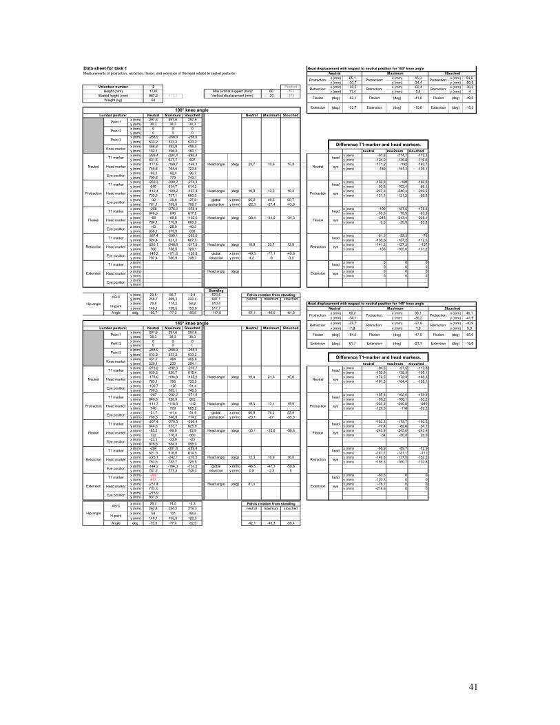
x (mm) 65,1 x (mm) 45,3 x (mm) 54,6y (mm) -30,7 y (mm) -34,4 y (mm) -50,5
2 Position x (mm) -30,5 x (mm) -62,4 x (mm) -36,31730 60 -1F5 y (mm) 11,4 y (mm) 0,4 y (mm) -4867,2 917,2 -20 -1F3
64
Neutral Maximum Slouched Neutral Maximum Slouchedx (mm) 297,6 297,6 297,6y (mm) 38,3 38,3 38,3x (mm) 0 0 0y (mm) 0 0 0x (mm) -268,9 -268,9 -268,9y (mm) 533,2 533,2 533,2x (mm) 466,8 483,9 406,5y (mm) 182,1 196,2 180,1 neutral maximum slouchedx (mm) -269,4 -284,4 -280,4 x (mm) -91,8 -114,7 -112,3y (mm) 631,6 627,7 607 y (mm) -124,2 -136,8 -116,6x (mm) -177,6 -169,7 -168,1 Head angle (deg) 23,7 10,6 15,3 x (mm) -171,2 -192 -183,7y (mm) 755,8 764,5 723,6 y (mm) -159 -151,3 -136,1x (mm) -98,2 -92,4 -96,7y (mm) 790,6 779 743,1x (mm) -269,3 -280,2 -274,3 x (mm) -156,9 -160 -166,9y (mm) 640 634,7 614,2 y (mm) -93,5 -102,4 -66,1x (mm) -112,4 -120,2 -107,4 Head angle (deg) 18,9 13,2 18,3 x (mm) -237,3 -240,4 -246,5y (mm) 733,5 737,1 680,3 y (mm) -121,1 -121,2 -92,5x (mm) -32 -39,8 -27,8 global x (mm) 65,2 49,5 60,7y (mm) 761,1 755,9 706,7 protraction y (mm) -22,3 -27,4 -43,3x (mm) -258 -276,3 -278,4 x (mm) -190 -187,5 -175,8y (mm) 648,6 640 617,2 y (mm) -55,5 -75,9 -63,3x (mm) -68 -88,8 -102,6 Head angle (deg) -38,4 -31,0 -34,3 x (mm) -248 -247,4 -238,1y (mm) 704,1 715,9 680,5 y (mm) -9,5 -39,9 -20,8x (mm) -10 -28,9 -40,3y (mm) 658,1 679,9 638x (mm) -287,4 -299,1 -293,9 x (mm) -61,3 -52,3 -76y (mm) 624,4 621,3 607,5 y (mm) -135,6 -137,2 -112,6x (mm) -226,1 -246,8 -217,9 Head angle (deg) 18,9 20,7 12,9 x (mm) -141,2 -127,3 -157y (mm) 760 758,5 720,1 y (mm) -163 -165,6 -131,2x (mm) -146,2 -171,8 -136,9 global x (mm) -48,5 -77,1 -49,8y (mm) 787,4 786,9 738,7 retraction y (mm) 4,2 -6 -3,5x (mm) x (mm) 0 0 0y (mm) y (mm) 0 0 0x (mm) Head angle (deg) x (mm) 0 0 0y (mm) y (mm) 0 0 0x (mm)y (mm)
Standingx (mm) 29,5 85,7 -0,4 578,5y (mm) 256,7 265,3 220,4 647,1 neutral maximum slouchedx (mm) 79,8 114,2 56,8 510,4y (mm) 140,1 139,5 133,9 517,7
Angle deg. -66,7 -77,2 -56,5 -117,8 -51,1 -40,5 -61,2 x (mm) 60,7 x (mm) 66,1 x (mm) 46,1y (mm) -34,7 y (mm) -35,2 y (mm) -41,9x (mm) -25,7 x (mm) -37,8 x (mm) -40,9
Neutral Maximum Slouched Neutral Maximum Slouched y (mm) 7,8 y (mm) 1,8 y (mm) 5,9x (mm) 297,6 297,6 297,6y (mm) 38,3 38,3 38,3x (mm) 0 0 0y (mm) 0 0 0x (mm) -268,9 -268,9 -268,9y (mm) 533,2 533,2 533,2x (mm) 451,7 464 435,6y (mm) 220,1 233 204,1 neutral maximum slouchedx (mm) -273,2 -292,3 -279,7 x (mm) -94,6 -97,5 -113,8y (mm) 629,2 620,7 615,4 y (mm) -133,9 -135,3 -105,1x (mm) -178,6 -194,8 -165,9 Head angle (deg) 19,4 21,3 15,0 x (mm) -172,5 -172,3 -188,3y (mm) 763,1 756 720,5 y (mm) -161,3 -164,4 -125,1x (mm) -100,7 -120 -91,4y (mm) 790,5 785,1 740,5x (mm) -267 -282,2 -271,9 x (mm) -155,3 -163,6 -159,9y (mm) 640,8 628,9 622 y (mm) -99,2 -100,1 -63,2x (mm) -111,7 -118,6 -112 Head angle (deg) 19,5 13,1 19,9 x (mm) -235,3 -240,8 -240y (mm) 740 729 685,2 y (mm) -127,5 -118 -92,2x (mm) -31,7 -41,4 -31,9 global x (mm) 66,9 76,2 53,9y (mm) 768,3 746,9 714,2 protraction y (mm) -23,1 -27 -35,3x (mm) -267,4 -279,5 -266,4 x (mm) -182,2 -179,7 -193,5y (mm) 644,6 633,7 625,9 y (mm) -77,4 -82,6 -34,1x (mm) -85,2 -99,8 -72,9 Head angle (deg) -35,1 -25,8 -50,6 x (mm) -243,9 -245,6 -243,4y (mm) 722 716,3 660 y (mm) -34 -50,8 26,6x (mm) -23,5 -33,9 -23y (mm) 678,6 684,5 599,3x (mm) -294 -301,8 -289,4 x (mm) -68,9 -59,7 -72,9y (mm) 621,9 616,6 614,5 y (mm) -141,7 -137,1 -111x (mm) -225,1 -242,1 -216,5 Head angle (deg) 12,3 16,9 16,0 x (mm) -149,8 -137,5 -152,2y (mm) 763,6 753,7 725,5 y (mm) -159,3 -160,7 -133,8x (mm) -144,2 -164,3 -137,2 global x (mm) -46,5 -47,3 -50,6y (mm) 781,2 777,3 748,3 retraction y (mm) 0,5 -2,3 5x (mm) -292
613x (mm) -60,6 0 0
y (mm) y (mm) -120,3 0 0x (mm) -231,4 Head angle (deg) 81,0 x (mm) -76,1 0 0y (mm) 733,3 y (mm) -218,6 0 0x (mm) -215,9y (mm) 831,6
x (mm) 26,7 74,5 -2,3y (mm) 262,4 254,2 219,3 neutral maximum slouchedx (mm) 58 101 49,6y (mm) 140,1 135,3 120,3
Angle deg. -75,6 -77,4 -62,3 -42,1 -40,3 -55,4
Hip angle
Hip angle
ASIC
H-point
Head marker
ASIC
H-point
Point 1
Point 2
Retraction
Extension
Eye position
Eye position
Eye position
Eye position
Protraction
T1 marker
Head marker
T1 marker
Flexion
Eye position
Lumbar posture:
Head marker
T1 marker
Head marker
Eye position
Retraction Head marker
T1 marker
Head marker
Head marker
Point 3
Knee marker
T1 marker
Eye position
T1 marker
Extension
T1 marker
Head marker
Eye position
145° knee angle
Neutral
Flexion
head
(deg)
Eye position
Protraction
T1 marker
Head marker
Head marker
T1 marker
Retraction:
Difference T1-marker and head markers.
Neutral
Retraction:
Slouched
head
eye
head
head
Vertical displacement (mm):
eye
head
eye
T1 marker
Weight (kg)
Lumbar posture:
Knee marker
Point 3
Point 2
Point 1
Neutral
Eye position
eye
head
eye
head
head
eye
(deg)
head
eye
eye
Flexion
Retraction:
Flexion
Neutral
Protraction
Flexion
Retraction
Extension
Extension
Neutral
Data sheet for task 1Measurements of protraction, retraction, flexion, and extension of the head related to seated postures
Extension Extension100° knee angle
Volunteer numberHeight (mm)
Seated height (mm)Max lumbar support (mm):
Protraction:
Protraction
Retraction:
head
eye
Retraction:
eye
Head displacement with respect to neutral position for 100° knee angle
Flexion Flexion Flexion (deg)
Maximum Slouched
Protraction: Protraction:
(deg)
-41,6
-10,6
Retraction:
(deg)
-49,6
-15,3
Head displacement with respect to neutral position for 145° knee angle
Extension
(deg)
(deg)
-62,1
-23,7
(deg)
-15,0
Flexion (deg) -65,6
Extension (deg)(deg) -21,3
-54,5 Flexion (deg) -47,0
61,7 Extension
Pelvis rotation from standing
Pelvis rotation from standing
Protraction:Protraction:Protraction:
Retraction
Extension
Difference T1-marker and head markers.
Neutral Maximum
41
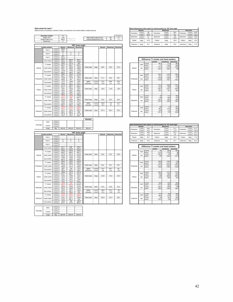
x (mm) 48 x (mm) 52,4 x (mm) 42,8y (mm) -23,6 y (mm) -6,1 y (mm) -10,1
3 Position x (mm) -57,1 x (mm) -60 x (mm) -59,91730 60 -1F5 y (mm) -5 y (mm) -32,9 y (mm) 3,5869,2 919,2 -20 -1F3
71
Neutral Maximum Slouched Neutral Maximum Slouchedx (mm) 296,9y (mm) 43,2x (mm) 0 0 0y (mm) 0 0 0x (mm) -283,1y (mm) 533,8x (mm) 443,1 464,8 405,1y (mm) 225,6 234,1 235,8 neutral maximum slouchedx (mm) -294,2 -321,8 -287 x (mm) -94,1 -71,4 -96,5y (mm) 649,1 630,1 639,7 y(mm) -111 -118,5 -69,9x (mm) -200,1 -250,4 -190,5 Head angle (deg) 28,6 29,0 24,3 x (mm) -171,4 -147,4 -176,6y (mm) 760,1 748,6 709,6 y(mm) -153,1 -160,7 -106x (mm) -122,8 -174,4 -110,4y (mm) 802,2 790,8 745,7x (mm) -268,7 -305,4 -273,6 x (mm) -142,1 -123,8 -139,3y (mm) 662,2 638,6 643,5 y(mm) -87,4 -112,4 -59,8x (mm) -126,6 -181,6 -134,3 Head angle (deg) 31,2 28,5 29,7 x (mm) -216,8 -198,8 -217y (mm) 749,6 751 703,3 y(mm) -132,6 -153,1 -104,2x (mm) -51,9 -106,6 -56,6 global x (mm) 73,5 68,8 56,2y (mm) 794,8 791,7 747,7 protraction y (mm) -10,5 2,4 -6,3x (mm) -271,3 -305,3 -257,1 x (mm) -171,2 -142,8 -174,7y (mm) 672,7 643,1 649,4 y(mm) -61,8 -95,6 -13,8x (mm) -100,1 -162,5 -82,4 Head angle (deg) -29,2 -14,8 -45,8 x (mm) -235,1 -216,7 -229,5y (mm) 734,5 738,7 663,2 y(mm) -26,1 -76,1 42,5x (mm) -36,2 -88,6 -27,6y (mm) 698,8 719,2 606,9x (mm) -329,6 -339,8 -318,8 x (mm) -37 -11,4 -36,6y (mm) 637,4 629 641,3 y(mm) -106 -85,6 -73,4x (mm) -292,6 -328,4 -282,2 Head angle (deg) 43,6 52,2 46,3 x (mm) -101,4 -66,2 -99,4y (mm) 743,4 714,6 714,7 y(mm) -167,3 -156,3 -139,1x (mm) -228,2 -273,6 -219,4 global x (mm) -92,5 -78 -91,7y (mm) 804,7 785,3 780,4 retraction y (mm) -16,7 -34 5,1x (mm) -330,9 -336,2 -326,8 x (mm) 0,2 7,3 -23,7y (mm) 630,2 622,3 626,2 y(mm) -65,2 -61,6 -69,8x (mm) -331,1 -343,5 -303,1 Head angle (deg) 107,7 104,1 95,2 x (mm) 30,9 31,2 -14,9y (mm) 695,4 683,9 696 y(mm) -161,3 -157 -165,9x (mm) -361,8 -367,4 -311,9y (mm) 791,5 779,3 792,1
Standingx (mm)y (mm)x (mm)y (mm)
Angle deg. #DIV/0! #DIV/0! #DIV/0! #DIV/0! x (mm) 53,6 x (mm) 71,7 x (mm) 51,7y (mm) -15,7 y (mm) -11,9 y (mm) -23,3x (mm) -44,4 x (mm) -34,7 x (mm) -37,7
Neutral Maximum Slouched Neutral Maximum Slouched y (mm) -2,2 y (mm) -15 y (mm) 22,5x (mm)y (mm)x (mm) 0 0 0y (mm) 0 0 0x (mm)y (mm)x (mm) 431,1 446 376,4y (mm) 243,7 273,8 251,8 neutral maximum slouchedx (mm) -304,9 -330,4 -296,2 x (mm) -87 -59,2 -80,3y (mm) 650,3 628,4 641,3 y(mm) -113,3 -113,2 -82x (mm) -217,9 -271,2 -215,9 Head angle (deg) 29,2 33,3 25,8 x (mm) -165,3 -134 -163y (mm) 763,6 741,6 723,3 y(mm) -157 -162,4 -121,9x (mm) -139,6 -196,4 -133,2y (mm) 807,3 790,8 763,2x (mm) -285,2 -308,4 -282,9 x (mm) -140,6 -130,9 -132y (mm) 663,2 639,9 647,2 y(mm) -97,6 -101,3 -58,7x (mm) -144,6 -177,5 -150,9 Head angle (deg) 26,2 29,1 29,7 x (mm) -215,5 -206,4 -210,5y (mm) 760,8 741,2 705,9 y(mm) -134,4 -143,4 -103,5x (mm) -69,7 -102 -72,4 global x (mm) 73,3 93,7 65y (mm) 797,6 783,3 750,7 protraction y (mm) -2,8 -0,4 -17,4x (mm) -288,6 -307,5 -267,9 x (mm) -163,2 -147,9 -175,5y (mm) 670,7 644,7 651,9 y(mm) -76,6 -89,9 -20,4x (mm) -125,4 -159,6 -92,4 Head angle (deg) -23,5 -16,4 -45,7 x (mm) -230 -220,2 -228,4y (mm) 747,3 734,6 672,3 y(mm) -47,5 -68,6 33,8x (mm) -58,6 -87,3 -39,5y (mm) 718,2 713,3 618,1x (mm) -330,4 -343 -317,5 x (mm) -42,6 -24,5 -42,6y (mm) 642,2 628,6 613,9 y(mm) -111,1 -98,2 -104,5x (mm) -287,8 -318,5 -274,9 Head angle (deg) 42,5 45,5 43,3 x (mm) -105,1 -85,9 -108y (mm) 753,3 726,8 718,4 y(mm) -168,3 -160,6 -166,1x (mm) -225,3 -257,1 -209,5 global x (mm) -69,9 -47,3 -59y (mm) 810,5 789,2 780 retraction y (mm) -10,3 -14,8 -4,9x (mm) -332,8 -340,3 -320,4 x (mm) -14,7 10,8 -30,6y (mm) 634,4 623,4 630,5 y(mm) -80,2 -57,9 -72,5x (mm) -318,1 -351,1 -289,8 Head angle (deg) 100,0 107,4 90,0 x (mm) 2,8 39,7 -30,6y (mm) 714,6 681,3 703 y(mm) -179,1 -150 -171,8x (mm) -335,6 -380 -289,8y (mm) 813,5 773,4 802,3
x (mm)y (mm)x (mm)y (mm)
Angle deg. #DIV/0! #DIV/0! #DIV/0!
(deg) 64,2
Flexion (deg) -71,5
(deg) 74,1 Extension
-52,7 Flexion (deg) -49,8
70,9 Extension
(deg)
-70,0
71,0
Head displacement with respect to neutral position for 145° knee angle
Extension
(deg)
(deg)
-57,8
79,1
(deg)
Protraction: Protraction:
(deg)
-43,8
75,0
Retraction:
Flexion Flexion
Extension
(deg)
Maximum Slouched
Retraction
Protraction
Retraction:
Retraction:
Flexion
Neutral
Protraction
Extension
Difference T1-marker and head markers.
Neutral Maximum
Flexion
Extension
head
eye
Neutral
Data sheet for task 1Measurements of protraction, retraction, flexion, and extension of the head related to seated postures
Extension100° knee angle
Volunteer numberHeight (mm)
Seated height (mm)
Protraction:
Neutral
Retraction:
head
Max lumbar support (mm):
Head displacement with respect to neutral position for 100° knee angle
(deg)
head
eye
Vertical displacement (mm):
head
eye
(deg)
head
eye
eye
eye
head
eye
head
Weight (kg)
head
eye
Flexion
Flexion
Lumbar posture:
Knee marker
Point 3
Retraction:145° knee angle
T1 marker
Head marker
Head marker
T1 marker
Head marker
Difference T1-marker and head markers.
Extension
Slouched
head
eye
head
eye
T1 marker
Retraction:
Protraction:
Extension
Retraction
Eye position
Eye position
Protraction
Retraction
Eye position
Flexion
Head marker
T1 marker
Head marker
Head marker
Point 2
Point 1
Lumbar posture:
Head marker
T1 marker
Head marker
Eye position
T1 marker
Neutral
Eye position
Eye position
Retraction
Extension
Eye position
Eye position
Eye position
Eye position
Protraction
T1 marker
Hip angle
Hip angle
ASIC
H-point
Head marker
ASIC
H-point
T1 marker
Point 1
Point 2
T1 marker
Protraction:Protraction:
Flexion
Neutral
T1 marker
Head marker
Point 3
Knee marker
42
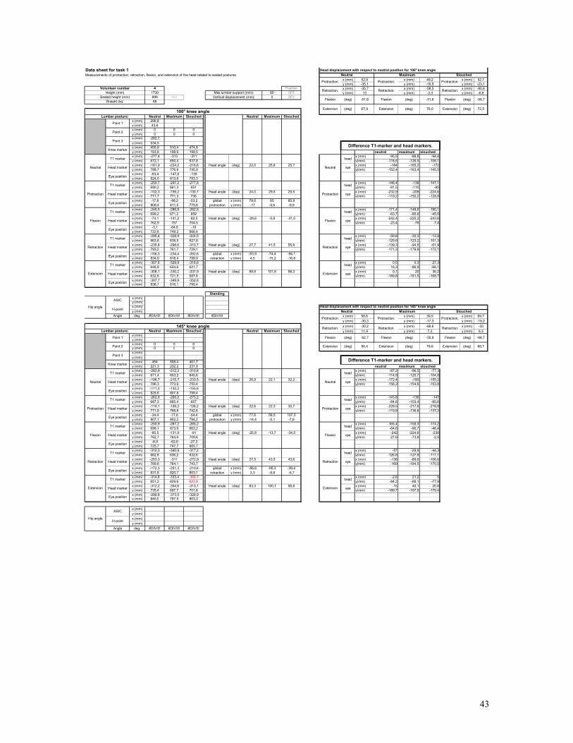
x (mm) 52,9 x (mm) 49,2 x (mm) 52,7y (mm) -35,1 y (mm) -16,5 y (mm) -23,1
4 Position x (mm) -35,7 x (mm) -58,5 x (mm) -80,61730 60 0F5 y (mm) 13 y (mm) -3,3 y (mm) -6,8899 949 0 0F368
Neutral Maximum Slouched Neutral Maximum Slouchedx (mm) 296,8y (mm) 43,6x (mm) 0 0 0y (mm) 0 0 0x (mm) -282,3y (mm) 534,5x (mm) 455,9 510,4 474,8y (mm) 193,8 198,6 199,5 neutral maximum slouchedx (mm) -277,4 -313 -311 x (mm) -95,5 -88,8 -94,4y (mm) 672,1 650,4 637,8 y(mm) -116,6 -126,5 -108,1x (mm) -181,9 -224,2 -216,6 Head angle (deg) 22,0 25,8 25,7 x (mm) -184 -165,2 -172y (mm) 788,7 776,9 745,9 y(mm) -152,4 -163,4 -145,5x (mm) -93,4 -147,8 -139y (mm) 824,5 813,8 783,3x (mm) -250,7 -297,2 -277,8 x (mm) -148,4 -138 -147,1y (mm) 690,2 661,3 651 y(mm) -81,5 -110 -85x (mm) -102,3 -159,2 -130,7 Head angle (deg) 24,0 29,5 29,5 x (mm) -232,9 -209 -224,6y (mm) 771,7 771,3 736 y(mm) -119,2 -150,2 -128,8x (mm) -17,8 -88,2 -53,2 global x (mm) 79,6 65 85,9y (mm) 809,4 811,5 779,8 protraction y (mm) -17 -5,6 -9,9x (mm) -245,5 -289,8 -262,6 x (mm) -171,4 -148,6 -180,1y (mm) 699,2 671,2 659 y(mm) -63,7 -85,8 -45,5x (mm) -74,1 -141,2 -82,5 Head angle (deg) -29,6 -5,8 -31,0 x (mm) -242,4 -225,2 -243,6y (mm) 762,9 757 704,5 y(mm) -23,4 -78 -7,4x (mm) -3,1 -64,6 -19y (mm) 722,6 749,2 666,4x (mm) -295,6 -328,9 -324,5 x (mm) -59,8 -30,3 -13,8y (mm) 663,6 638,5 627,8 y(mm) -129,6 -123,2 -101,3x (mm) -235,8 -298,6 -310,7 Head angle (deg) 27,7 41,5 55,8 x (mm) -139,3 -94,5 -61,9y (mm) 793,2 761,7 729,1 y(mm) -171,3 -179,9 -172,1x (mm) -156,3 -234,4 -262,6 global x (mm) -53,9 -74,4 -94,1y (mm) 834,9 818,4 799,9 retraction y (mm) 4,5 -15,2 -16,8x (mm) -307,6 -329,9 -316,6 x (mm) 0,5 0,3 21,3y (mm) 648,9 634,6 621,7 y(mm) 16,3 -86,9 -66,1x (mm) -308,1 -330,2 -337,9 Head angle (deg) 89,9 101,8 98,3 x (mm) 0,1 20 36,2y (mm) 632,6 721,5 687,8 y(mm) -189,8 -181,5 -168,7x (mm) -307,7 -349,9 -352,8y (mm) 838,7 816,1 790,4
Standingx (mm)y (mm)x (mm)y (mm)
Angle deg. #DIV/0! #DIV/0! #DIV/0! #DIV/0! x (mm) 56,6 x (mm) 39,5 x (mm) 69,7y (mm) -30,3 y (mm) -17,3 y (mm) -19,2x (mm) -30,2 x (mm) -66,6 x (mm) -33
Neutral Maximum Slouched Neutral Maximum Slouched y (mm) 11,9 y (mm) 7,2 y (mm) 6,3x (mm)y (mm)x (mm) 0 0 0y (mm) 0 0 0x (mm)y (mm)x (mm) 454 508,4 461,7y (mm) 221,3 232,2 231,9 neutral maximum slouchedx (mm) -283,9 -312,2 -310,8 x (mm) -87,2 -96,5 -77,3y (mm) 671,4 653,2 645,6 y(mm) -114,9 -120,7 -104,8x (mm) -196,7 -215,7 -233,5 Head angle (deg) 26,9 22,1 32,2 x (mm) -172,4 -180 -155,2y (mm) 786,3 773,9 750,4 y(mm) -158,2 -154,6 -153,8x (mm) -111,5 -132,2 -155,6y (mm) 829,6 807,8 799,4x (mm) -262,9 -295,2 -273,2 x (mm) -143,8 -136 -147y (mm) 687,3 665,4 657 y(mm) -84,6 -103,4 -85,6x (mm) -119,1 -159,2 -126,2 Head angle (deg) 22,6 22,3 35,7 x (mm) -228,5 -217,6 -218,8y (mm) 771,9 768,8 742,6 y(mm) -119,8 -136,8 -137,2x (mm) -34,4 -77,6 -54,4 global x (mm) 77,6 56,5 107,3y (mm) 807,1 802,2 794,2 protraction y (mm) -14,4 -5,1 -7,8x (mm) -250,9 -287,2 -265,2 x (mm) -165,4 -155,3 -174,2y (mm) 698,1 673,9 663,2 y(mm) -64,6 -90,7 -46,4x (mm) -85,5 -131,9 -91 Head angle (deg) -25,8 -13,7 -34,5 x (mm) -242 -224,6 -238y (mm) 762,7 764,6 709,6 y(mm) -27,6 -73,8 -2,5x (mm) -8,9 -62,6 -27,2y (mm) 725,7 747,7 665,7x (mm) -310,3 -340,9 -317,2 x (mm) -57 -29,9 -44,3y (mm) 662,8 636,2 632,6 y(mm) -126,8 -127,9 -111,1x (mm) -253,3 -311 -272,9 Head angle (deg) 27,5 43,5 43,6 x (mm) -138 -89,6 -106,6y (mm) 789,6 764,1 743,7 y(mm) -169 -184,5 -170,5x (mm) -172,3 -251,3 -210,6 global x (mm) -56,6 -95,3 -39,4y (mm) 831,8 820,7 803,1 retraction y (mm) 3,3 -9,8 -6,7x (mm) -314,8 -333,4 -308,1 x (mm) -2,6 21,2 5y (mm) 651,2 629,6 623,9 y(mm) -84,2 -68,1 -77,9x (mm) -312,2 -354,6 -313,1 Head angle (deg) 83,3 100,7 98,8 x (mm) -15 40,1 20,8y (mm) 735,4 697,7 701,8 y(mm) -189,7 -167,9 -179,4x (mm) -299,8 -373,5 -328,9y (mm) 840,9 797,5 803,3
x (mm)y (mm)x (mm)y (mm)
Angle deg. #DIV/0! #DIV/0! #DIV/0!
Protraction:Protraction:Protraction:
Hip angle
Hip angle
ASIC
H-point
Head marker
ASIC
H-point
Point 1
Point 2
Flexion
Neutral
T1 marker
Head marker
Point 3
Knee marker
Eye position
Retraction
Extension
Eye position
Eye position
Eye position
Eye position
Protraction
T1 marker
Head marker
T1 marker
Extension
Eye position
Protraction
Retraction
Eye position
Flexion
Eye position
Head marker
T1 marker
Lumbar posture:
Knee marker
Point 3
Point 2
Point 1
Head marker
T1 marker
Head marker
Neutral
Eye position
Lumbar posture:
Head marker
T1 marker
Head marker
Eye position
T1 marker
T1 marker
head
Extension
Neutral
Protraction
Retraction:
Flexion
Head displacement with respect to neutral position for 145° knee angle
Retraction:
Slouched
head
eye
head
head
eye
eye
Weight (kg)
Retraction: Retraction:
Difference T1-marker and head markers.
145° knee angle
T1 marker
Head marker
Head marker
T1 marker
head
Vertical displacement (mm):
eye
eye
(deg)
(deg)
head
eye
eye
head
eye
head
Data sheet for task 1Measurements of protraction, retraction, flexion, and extension of the head related to seated postures
Extension Extension100° knee angle
Volunteer numberHeight (mm)
Seated height (mm)Max lumbar support (mm):
Head displacement with respect to neutral position for 100° knee angle
Neutral
Protraction
Flexion
Retraction
Retraction
Extension
Difference T1-marker and head markers.
Neutral Maximum
Flexion
Extension
head
eye
Flexion Flexion Flexion (deg)(deg)
Maximum Slouched
Protraction: Protraction: Protraction:
Neutral
Retraction:
(deg)
-56,7
72,5
Retraction:
(deg)
-31,6
76,0 Extension
(deg)
(deg) 78,6
(deg)
-51,6
67,9
head
56,4 Extension
eye
-52,7 Flexion (deg) -35,8
(deg) 66,7
Flexion (deg) -66,7
Extension
43
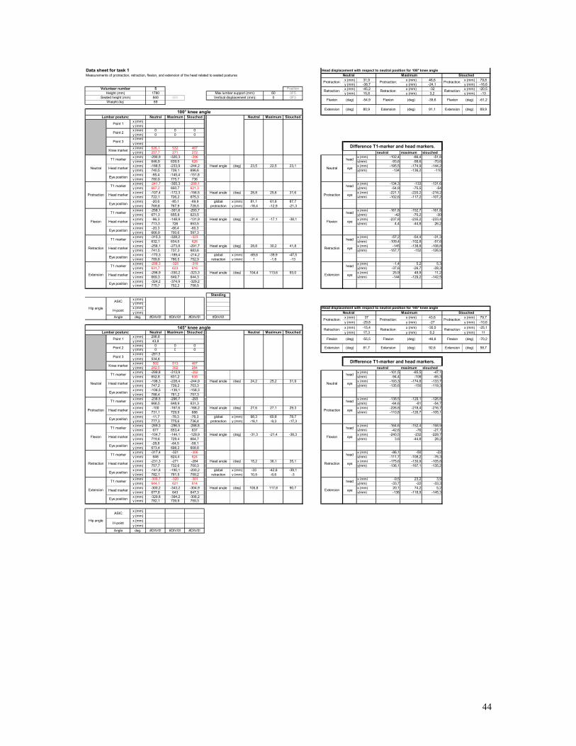
x (mm) 31,9 x (mm) 46,6 x (mm) 79,8y (mm) -38,7 y (mm) -24,1 y (mm) -16,6
5 Position x (mm) -45,2 x (mm) -32 x (mm) -20,51780 60 0F5 y (mm) 15,8 y (mm) 3,2 y (mm) -13840 890 0 0F369
Neutral Maximum Slouched Neutral Maximum Slouchedx (mm)y (mm)x (mm) 0 0 0y (mm) 0 0 0x (mm)y (mm)x (mm) 526,1 532 467y (mm) 257,7 271 272 neutral maximum slouchedx (mm) -290,9 -320,3 x -296 (mm) -102,4 -86,4 -51,8y (mm) 646,9 639,5 626 y(mm) -93,6 -99,6 -70,6x (mm) -188,5 -233,9 -244,2 Head angle (deg) 23,5 22,5 23,1 x (mm) -195,5 -174,9 -144,2y (mm) 740,5 739,1 696,6 y(mm) -134 -136,2 -110x (mm) -95,4 -145,4 -151,8y (mm) 780,9 736775,7x (mm) -241,7 -288,1-305,3 x (mm) -134,3 -133 -131,6y (mm) 667,2 621,3650,7 y(mm) -54,9 -75,5 -54x (mm) -107,4 -172,3 -156,5 Head angle (deg) 28,8 25,6 31,6 x (mm) -221,1 -220,2 -218,2y (mm) 722,1 726,2 675,3 y(mm) -102,6 -117,2 -107,2x (mm) -20,6 -85,1 -69,9 global x (mm) 81,1 61,6 87,7y (mm) 769,8 767,9 728,5 protraction y (mm) -18,4 -12,9 -21,3x (mm) -258,1 -301,6 -293,7 x (mm) -161,8 -152,7 -161,8y (mm) 671,3 655,8 623,5 y(mm) -42 -70,2 -30x (mm) -96,3 -148,9 -131,9 Head angle (deg) -31,4 -17,1 -38,1 x (mm) -237,8 -235,2 -233,4y (mm) 713,3 726 653,5 y(mm) 4,4 -44,8 26,2x (mm) -20,3 -66,4 -60,3y (mm) 666,9 700,6x
597,3(mm) -315,3 -328,2 x -323 (mm) -57,2 -54,4 -31,3
y (mm) 632,1 634,5 626 y(mm) -109,4 -102,8 -57,6x (mm) -258,1 -273,8 -291,7 Head angle (deg) 28,8 30,2 41,8 x (mm) -145 -138,8 -108,8y (mm) 741,5 737,3 683,6 y(mm) -157,7 -152 -126,9x (mm) -170,3 -189,4 -214,2 global x (mm) -69,6 -39,9 -47,5y (mm) 789,8 786,5 752,9 retraction y (mm) 1 -1,8 -13x (mm) -298,3 -325 -318 x (mm) -1,4 5,2 5,3y (mm) 631,7 623 616 y(mm) -37,6 -26,7 -28,3x (mm) -296,9 -330,2 -323,3 Head angle (deg) 104,4 113,6 93,0 x (mm) 25,9 49,9 11,2y (mm) 669,3 649,7 644,3 y(mm) -144 -129,2 -142,5x (mm) -324,2 -374,9 -329,2y (mm) 775,7 752,2 758,5
Standingx (mm)y (mm)x (mm)y (mm)
Angle deg. #DIV/0! #DIV/0! #DIV/0! #DIV/0! x (mm) 37 x (mm) 43,6 x (mm) 79,7y (mm) -29,8 y (mm) -27 y (mm) -10,6x (mm) -15,4 x (mm) -35,5 x (mm) -25,1
Neutral Maximum Slouched Neutral Maximum Slouched y (mm) 17,3 y (mm) 0,2 y (mm) 11x (mm) 296,8y (mm) 43,8x (mm) 0 0 0y (mm) 0 0 0x (mm) -281,9y (mm) 534,x
6(mm) 502 513 467
y (mm) 282,5 302 284 neutral maximum slouchedx (mm) -299,8 -313,9 x -292 (mm) -101,5 -85,5 -47,1y (mm) 652,8 631,2 638 y(mm) -94,4 -108 -65,3x (mm) -198,3 -228,4 -244,9 Head angle (deg) 24,2 25,2 31,9 x (mm) -193,3 -174,8 -133,7y (mm) 747,2 739,2 703,3 y(mm) -135,6 -150 -119,3x (mm) -106,5 -139,1 -158,3y (mm) 788,4 781,2 757,3x (mm) -238,5 -296,7 -293 x (mm) -138,5 -129,1 -126,8y (mm) 666,5 648,9 631,3 y(mm) -64,6 -81 -54,7x (mm) -100 -167,6 -166,2 Head angle (deg) 27,6 27,1 29,3 x (mm) -226,8 -218,4 -216,7y (mm) 731,1 729,9 686 y(mm) -110,8 -126,7 -105,1x (mm) -11,7 -78,3 -76,3 global x (mm) 98,3 60,8 78,7y (mm) 777,3 775,6 736,4 protraction y (mm) -16,1 -9,3 -17,3x (mm) -269,3 -296,5 -288,8 x (mm) -164,6 -152,4 -158,9y (mm) 677 653,4 637 y(mm) -42,6 -76 -27,7x (mm) -104,7 -144,1 -129,9 Head angle (deg) -31,3 -21,4 -38,3 x (mm) -240,5 -232 -229,7y (mm) 719,6 729,4 664,7 y(mm) 3,6 -44,8 28,2x (mm) -28,8 -64,5 -59,1y (mm) 673,4 698,2x
608,8(mm) -317,4 -321 x -306 (mm) -86,1 -50 -22
y (mm) 646 624,4 624 y(mm) -111,7 -108,2 -76,3x (mm) -231,3 -271 -284 Head angle (deg) 15,2 36,1 35,1 x (mm) -175,6 -130,9 -105,8y (mm) 757,7 732,6 700,3 y(mm) -136,1 -167,1 -135,2x (mm) -141,8 -190,1 -200,2 global x (mm) -33 -42,6 -39,1y (mm) 782,1 791,5 759,2 retraction y (mm) 10,5 -6,6 -3x (mm) -309,7 -320 -301 x (mm) -9,5 23,2 3,9y (mm) 644,1 621 614 y(mm) -33,7 -22 -33,3x (mm) -300,2 -343,2 -304,9 Head angle (deg) 105,8 117,8 90,7 x (mm) 20,1 74,2 5,2y (mm) 677,8 643 647,3 y(mm) -138 -118,9 -145,3x (mm) -329,8 -394,2 -306,2y (mm) 782,1 739,9 759,3
x (mm)y (mm)x (mm)y (mm)
Angle deg. #DIV/0! #DIV/0! #DIV/0!
(deg) 58,7
Flexion (deg) -70,2
Extension
-55,5 Flexion (deg) -46,6
81,7 Extension
eye
(deg) 92,6
(deg)
(deg)
-54,9
80,9
Retraction:
(deg)
-61,2
69,9
Retraction:
(deg)
-39,6
91,1 Extension
(deg)
Head displacement with respect to neutral position for 100° knee angle
Flexion Flexion Flexion (deg)
Maximum Slouched
Protraction: Protraction: Protraction:
Retraction
Extension
Difference T1-marker and head markers.
Neutral Maximum
Flexion
Extension
head
eye
Neutral
Protraction
Flexion
Retraction
Data sheet for task 1Measurements of protraction, retraction, flexion, and extension of the head related to seated postures
Extension Extension100° knee angle
Volunteer numberHeight (mm)
Seated height (mm)Max lumbar support (mm):
Vertical displacement (mm):
eye
head
eye
head
eye
eye
(deg)
(deg)
head
eye
head
Weight (kg)
Retraction: Retraction:
Difference T1-marker and head markers.
145° knee angle
T1 marker
Head marker
Head marker
T1 marker
head
Neutral
Retraction:
Slouched
head
eye
head
head
eye
eye
T1 marker
T1 marker
head
Extension
Neutral
Protraction
Retraction:
Flexion
Head displacement with respect to neutral position for 145° knee angle
Head marker
T1 marker
Head marker
Neutral
Eye position
Lumbar posture:
Head marker
T1 marker
Head marker
Eye position
Lumbar posture:
Knee marker
Point 3
Point 2
Point 1
Extension
Eye position
Protraction
Retraction
Eye position
Flexion
Eye position
Head marker
T1 marker
Retraction
Extension
Eye position
Eye position
Eye position
Eye position
Protraction
T1 marker
Head marker
T1 marker
Point 1
Point 2
Flexion
Neutral
T1 marker
Head marker
Point 3
Knee marker
Eye position
Protraction:Protraction:Protraction:
Hip angle
Hip angle
ASIC
H-point
Head marker
ASIC
H-point
44
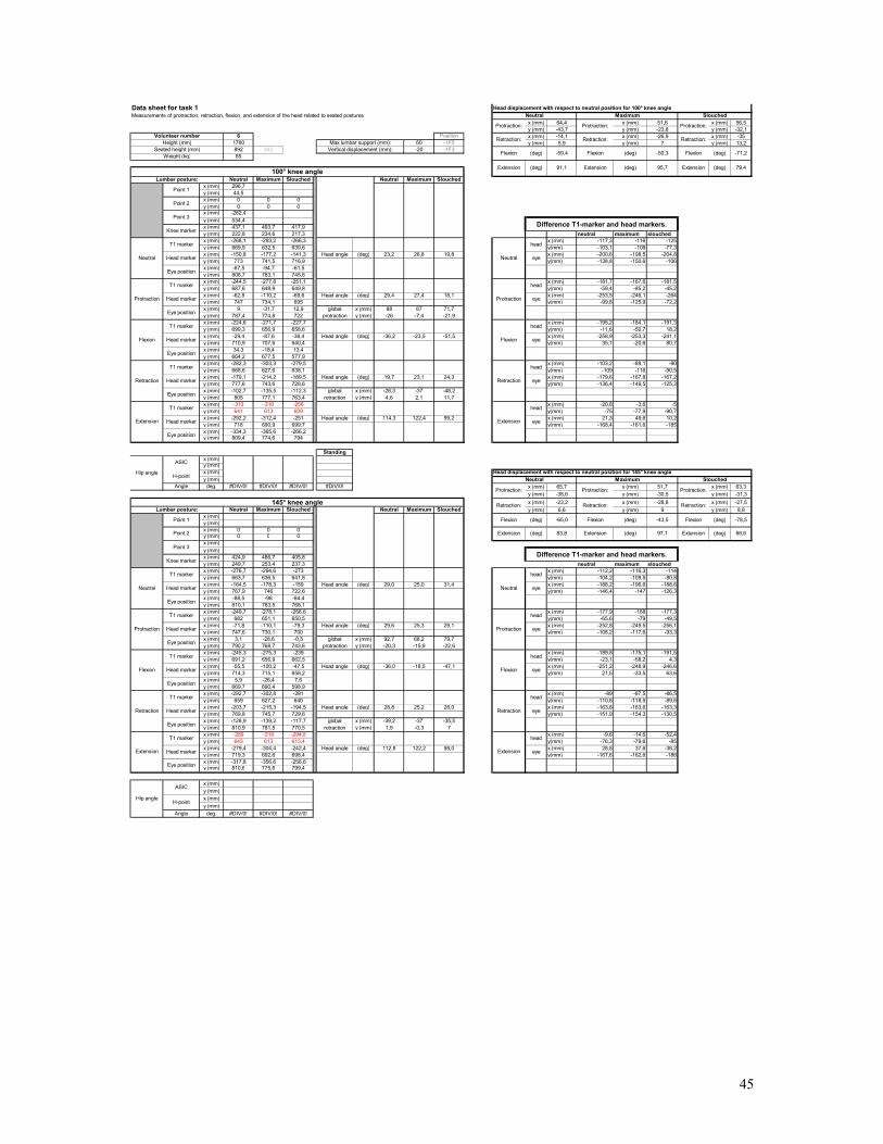
x (mm) 64,4 x (mm) 51,6 x (mm) 56,5y (mm) -43,7 y (mm) -23,8 y (mm) -32,1
6 Position x (mm) -14,1 x (mm) -26,9 x (mm) -351760 60 -1F5 y (mm) 5,9 y (mm) 7 y (mm) 13,2892 942 -20 -1F385
Neutral Maximum Slouched Neutral Maximum Slouchedx (mm) 296,7y (mm) 44,5x (mm) 0 0 0y (mm) 0 0 0x (mm) -282,4y (mm) 534,4x (mm) 437,1 493,7 417,9y (mm) 222,8 234,6 217,3 neutral maximum slouchedx (mm) -268,1 -293,2 -266,3 x (mm) -117,3 -116 -125y (mm) 669,9 632,5 639,6 y(mm) -103,1 -109 -77,3x (mm) -150,8 -177,2 -141,3 Head angle (deg) 23,2 26,8 19,8 x (mm) -200,6 -198,5 -204,8y (mm) 773 741,5 716,9 y(mm) -138,8 -150,6 -106x (mm) -67,5 -94,7 -61,5y (mm) 808,7 783,1 745,6x (mm) -244,5 -277,8 -251,1 x (mm) -181,7 -167,6 -181,5y (mm) 687,6 648,9 649,8 y(mm) -59,4 -85,2 -45,2x (mm) -62,8 -110,2 -69,6 Head angle (deg) 29,4 27,4 18,1 x (mm) -253,5 -246,1 -264y (mm) 747 734,1 695 y(mm) -99,8 -125,9 -72,2x (mm) 9 -31,7 12,9 global x (mm) 88 67 71,7y (mm) 787,4 774,8 722 protraction y (mm) -26 -7,4 -21,9x (mm) -224,6 -271,7 -227,7 x (mm) -195,2 -184,1 -191,3y (mm) 699,3 656,9 658,6 y(mm) -11,6 -50,7 18,2x (mm) -29,4 -87,6 -36,4 Head angle (deg) -36,2 -23,5 -51,5 x (mm) -258,9 -253,3 -241,1y (mm) 710,9 707,6 640,4 y(mm) 35,1 -20,6 80,7x (mm) 34,3 -18,4 13,4y (mm) 664,2 677,5 577,9x (mm) -282,3 -303,3 -279,5 x (mm) -103,2 -89,1 -90y (mm) 668,6 627,6 638,1 y(mm) -109 -116 -90,5x (mm) -179,1 -214,2 -189,5 Head angle (deg) 19,7 23,1 24,3 x (mm) -179,6 -167,8 -167,2y (mm) 777,6 743,6 728,6 y(mm) -136,4 -149,5 -125,3x (mm) -102,7 -135,5 -112,3 global x (mm) -28,3 -37 -48,2y (mm) 805 777,1 763,4 retraction y (mm) 4,6 2,1 11,7x (mm) -313 -316 -256 x (mm) -20,8 -3,6 -5y (mm) 641 613 609 y(mm) -75 -77,9 -90,7x (mm) -292,2 -312,4 -251 Head angle (deg) 114,3 122,4 99,2 x (mm) 21,3 49,6 10,2y (mm) 716 690,9 699,7 y(mm) -168,4 -161,6 -185x (mm) -334,3 -365,6 -266,2y (mm) 809,4 774,6 794
Standingx (mm)y (mm)x (mm)y (mm)
Angle deg. #DIV/0! #DIV/0! #DIV/0! #DIV/0! x (mm) 65,7 x (mm) 51,7 x (mm) 63,3y (mm) -38,6 y (mm) -30,5 y (mm) -31,3x (mm) -23,2 x (mm) -28,8 x (mm) -27,5
Neutral Maximum Slouched Neutral Maximum Slouched y (mm) 6,6 y (mm) 9 y (mm) 8,8x (mm)y (mm)x (mm) 0 0 0y (mm) 0 0 0x (mm)y (mm)x (mm) 424,9 486,7 405,8y (mm) 249,7 253,4 237,3 neutral maximum slouchedx (mm) -276,7 -294,6 -273 x (mm) -112,2 -116,3 -114y (mm) 663,7 636,5 641,8 y(mm) -104,2 -109,5 -80,8x (mm) -164,5 -178,3 -159 Head angle (deg) 29,0 25,0 31,4 x (mm) -188,2 -196,6 -188,6y (mm) 767,9 746 722,6 y(mm) -146,4 -147 -126,3x (mm) -88,5 -98 -84,4y (mm) 810,1 783,5 768,1x (mm) -249,7 -278,1 -256,6 x (mm) -177,9 -168 -177,3y (mm) 682 651,1 650,5 y(mm) -65,6 -79 -49,5x (mm) -71,8 -110,1 -79,3 Head angle (deg) 29,6 25,3 29,1 x (mm) -252,8 -249,5 -256,1y (mm) 747,6 730,1 700 y(mm) -108,2 -117,6 -93,3x (mm) 3,1 -28,6 -0,5 global x (mm) 92,7 68,2 79,7y (mm) 790,2 768,7 743,8 protraction y (mm) -20,3 -15,9 -22,6x (mm) -245,3 -275,3 -239 x (mm) -189,8 -175,1 -191,5y (mm) 691,2 656,9 662,5 y(mm) -23,1 -58,2 4,3x (mm) -55,5 -100,2 -47,5 Head angle (deg) -36,0 -18,5 -47,1 x (mm) -251,2 -248,9 -246,6y (mm) 714,3 715,1 658,2 y(mm) 21,5 -33,5 63,6x (mm) 5,9 -26,4 7,6y (mm) 669,7 690,4 598,9x (mm) -292,7 -302,8 -281 x (mm) -89 -87,5 -86,5y (mm) 659 627,2 640 y(mm) -110,8 -118,5 -89,6x (mm) -203,7 -215,3 -194,5 Head angle (deg) 28,8 25,2 28,0 x (mm) -163,8 -163,6 -163,3y (mm) 769,8 745,7 729,6 y(mm) -151,9 -154,3 -130,5x (mm) -128,9 -139,2 -117,7 global x (mm) -39,2 -37 -35,5y (mm) 810,9 781,5 770,5 retraction y (mm) 1,9 -0,3 7x (mm) -289 -319 -294,8 x (mm) -9,6 -14,6 -52,4y (mm) 643 613 613,4 y(mm) -76,3 -79,6 -85x (mm) -279,4 -304,4 -242,4 Head angle (deg) 112,8 122,2 98,0 x (mm) 28,8 37,6 -38,2y (mm) 719,3 692,6 698,4 y(mm) -167,6 -162,6 -186x (mm) -317,8 -356,6 -256,6y (mm) 810,6 775,6 799,4
x (mm)y (mm)x (mm)y (mm)
Angle deg. #DIV/0! #DIV/0! #DIV/0!
Protraction:Protraction:Protraction:
Hip angle
Hip angle
ASIC
H-point
Head marker
ASIC
H-point
Point 1
Point 2
Flexion
Neutral
T1 marker
Head marker
Point 3
Knee marker
Eye position
Retraction
Extension
Eye position
Eye position
Eye position
Eye position
Protraction
T1 marker
Head marker
T1 marker
Extension
Eye position
Protraction
Retraction
Eye position
Flexion
Eye position
Head marker
T1 marker
Lumbar posture:
Knee marker
Point 3
Point 2
Point 1
Head marker
T1 marker
Head marker
Neutral
Eye position
Lumbar posture:
Head marker
T1 marker
Head marker
Eye position
T1 marker
T1 marker
head
Extension
Neutral
Protraction
Retraction:
Flexion
Head displacement with respect to neutral position for 145° knee angle
Retraction:
Slouched
head
eye
head
head
eye
eye
Weight (kg)
Retraction: Retraction:
Difference T1-marker and head markers.
145° knee angle
T1 marker
Head marker
Head marker
T1 marker
head
Vertical displacement (mm):
eye
eye
(deg)
(deg)
head
eye
eye
head
eye
head
Data sheet for task 1Measurements of protraction, retraction, flexion, and extension of the head related to seated postures
Extension Extension100° knee angle
Volunteer numberHeight (mm)
Seated height (mm)Max lumbar support (mm):
Head displacement with respect to neutral position for 100° knee angle
Neutral
Protraction
Flexion
Retraction
Retraction
Extension
Difference T1-marker and head markers.
Neutral Maximum
Flexion
Extension
head
eye
Flexion Flexion Flexion (deg)(deg)
Maximum Slouched
Protraction: Protraction: Protraction:
Neutral
Retraction:
(deg)
-71,2
79,4
Retraction:
(deg)
-50,3
95,7 Extension
(deg)
(deg) 97,1
(deg)
-59,4
91,1
head
83,8 Extension
eye
-65,0 Flexion (deg) -43,5
(deg) 66,6
Flexion (deg) -78,5
Extension
45
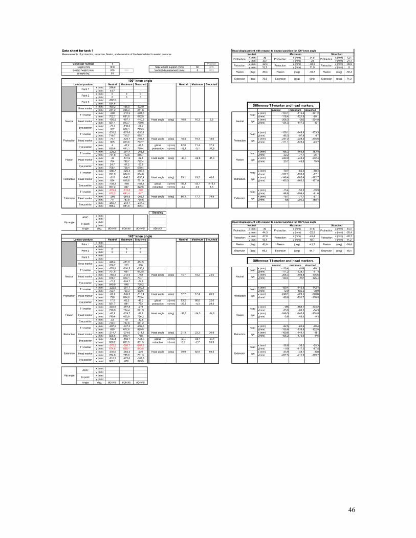
x (mm) 36 x (mm) 34,5 x (mm) 12,1y (mm) -33,1 y (mm) -24 y (mm) -21,1
7 Position x (mm) -52,4 x (mm) -30,2 x (mm) -90,81810 60 0F5 y (mm) 13,7 y (mm) 11,9 y (mm) 9915 965 0 0F391
Neutral Maximum Slouched Neutral Maximum Slouchedx (mm) 296,6y (mm) 44,7x (mm) 0 0 0y (mm) 0 0 0x (mm) -282,2y (mm) 534,6x (mm) 460,2 466,9 422,9y (mm) 241,2 256,3 241,6 neutral maximum slouchedx (mm) -280 -312,5 -281,5 x (mm) -123,1 -115,4 -141,2y (mm) 702,7 691,8 672,5 y(mm) -118,4 -121,9 -88,1x (mm) -156,9 -197,1 -140,3 Head angle (deg) 10,8 16,3 8,8 x (mm) -206,3 -202 -224,8y (mm) 821,1 813,7 760,6 y(mm) -134,3 -147,3 -101x (mm) -73,7 -110,5 -56,7y (mm) 837 839,1 773,5x (mm) -233,2 -275,6 -256,1 x (mm) -159,1 -149,9 -153,3y (mm) 719,7 715,7 675,7 y(mm) -85,3 -97,9 -67x (mm) -74,1 -125,7 -102,8 Head angle (deg) 18,3 19,3 18,0 x (mm) -237,2 -228,4 -235,6y (mm) 805 813,6 742,7 y(mm) -111,1 -125,4 -93,7x (mm) 4 -47,2 -20,5 global x (mm) 82,8 71,4 37,5y (mm) 830,8 841,1 769,4 protraction y (mm) -16,1 -0,1 -17,9x (mm) -225,2 -297,4 -266,3 x (mm) -195,2 -165,8 -183,8y (mm) 731,8 712,6 685,7 y(mm) -32,2 -77,1 -36,7x (mm) -30 -131,6 -82,5 Head angle (deg) -45,6 -22,8 -41,6 x (mm) -249,9 -240,2 -242,4y (mm) 764 789,7 722,4 y(mm) 23,7 -45,8 15,3x (mm) 24,7 -57,2 -23,9y (mm) 708,1 758,4 670,4x (mm) -286,7 -325,4 -305,8 x (mm) -70,7 -85,2 -50,4y (mm) 691,9 684,8 664,8 y(mm) -132,1 -133,8 -97,1x (mm) -216 -240,2 -255,4 Head angle (deg) 23,1 19,5 40,0 x (mm) -148,4 -165,4 -122,7y (mm) 824 818,6 761,9 y(mm) -165,3 -162,2 -157,8x (mm) -138,3 -160 -183,1 global x (mm) -59,1 -43,1 -115,1y (mm) 857,2 847 822,6 retraction y (mm) 2,9 4,9 1,3x (mm) -279,4 -315,8 -305 x (mm) -13,4 -50,3 -39,9y (mm) 672,2 681,4 647 y(mm) -98,8 -106,4 -91,6x (mm) -266 -265,5 -265,1 Head angle (deg) 86,3 77,1 79,9 x (mm) -19,7 -71,7 -57,1y (mm) 771 787,8 738,6 y(mm) -196 -200,2 -188,4x (mm) -259,7 -244,1 -247,9y (mm) 868,2 881,6 835,4
Standingx (mm)y (mm)x (mm)y (mm)
Angle deg. #DIV/0! #DIV/0! #DIV/0! #DIV/0! x (mm) 39 x (mm) 37,8 x (mm) 43,3y (mm) -44,3 y (mm) -22,6 y (mm) -20,4x (mm) -37,9 x (mm) -45,4 x (mm) -20,7
Neutral Maximum Slouched Neutral Maximum Slouched y (mm) 18,4 y (mm) 10,7 y (mm) 11,2x (mm)y (mm)x (mm) 0 0 0y (mm) 0 0 0x (mm)y (mm)x (mm) 446,4 461,9 414,5y (mm) 256,7 273 206 neutral maximum slouchedx (mm) -276,8 -320,5 -250,1 x (mm) -120,4 -108 -99,1y (mm) 701,5 691 612,8 y(mm) -117,2 -128,1 -91,3x (mm) -156,4 -212,5 -151 Head angle (deg) 14,7 18,2 24,0 x (mm) -205,3 -195,8 -175,6y (mm) 818,7 819,1 704,1 y(mm) -139,4 -157 -125,4x (mm) -71,5 -124,7 -74,5y (mm) 840,9 848 738,2x (mm) -222,6 -291,7 -260,8 x (mm) -159,4 -145,8 -142,4y (mm) 723,1 709,3 662,5 y(mm) -72,9 -105,5 -70,9x (mm) -63,2 -145,9 -118,4 Head angle (deg) 17,7 17,4 26,9 x (mm) -240,1 -229,5 -220,6y (mm) 796 814,8 733,4 y(mm) -98,6 -131,7 -110,5x (mm) 17,5 -62,2 -40,2 global x (mm) 93,2 66,6 32,6y (mm) 821,7 841 773 protraction y (mm) -22,7 -4,3 29,3x (mm) -246,9 -297,8 -271 x (mm) -186 -168,1 -173,2y (mm) 726,9 714,4 671,9 y(mm) -53,9 -86,5 -54,3x (mm) -60,9 -129,7 -97,8 Head angle (deg) -38,3 -24,5 -34,6 x (mm) -249,5 -240,8 -238,5y (mm) 780,8 800,9 726,2 y(mm) -3,8 -53,4 -9,3x (mm) 2,6 -57 -32,5y (mm) 730,7 767,8 681,2x (mm) -297,2 -337,2 -292,5 x (mm) -82,5 -62,6 -78,4y (mm) 690 677,6 655,5 y(mm) -135,6 -138,8 -102,5x (mm) -214,7 -274,6 -214,1 Head angle (deg) 21,3 23,3 30,9 x (mm) -160,8 -144,1 -151y (mm) 825,6 816,4 758 y(mm) -166,2 -173,9 -146x (mm) -136,4 -193,1 -141,5 global x (mm) -58,3 -62,1 -63,1y (mm) 856,2 851,5 801,5 retraction y (mm) 6,9 -2,7 53,9x (mm) -272,2 -320,7 -287,3 x (mm) -36,6 -36,3 -65,3y (mm) 674,6 668,1 643,8 y(mm) -110 -117,5 -87,5x (mm) -235,6 -284,4 -222 Head angle (deg) 79,9 82,9 69,4 x (mm) -53,9 -48,1 -100y (mm) 784,6 785,6 731,3 y(mm) -207,5 -211,9 -179,7x (mm) -218,3 -272,6 -187,3y (mm) 882,1 880 823,5
x (mm)y (mm)x (mm)y (mm)
Angle deg. #DIV/0! #DIV/0! #DIV/0!
Protraction:Protraction:Protraction:
Hip angle
Hip angle
ASIC
H-point
Head marker
ASIC
H-point
Point 1
Point 2
Flexion
Neutral
T1 marker
Head marker
Point 3
Knee marker
Eye position
Retraction
Extension
Eye position
Eye position
Eye position
Eye position
Protraction
T1 marker
Head marker
T1 marker
Extension
Eye position
Protraction
Retraction
Eye position
Flexion
Eye position
Head marker
T1 marker
Lumbar posture:
Knee marker
Point 3
Point 2
Point 1
Head marker
T1 marker
Head marker
Neutral
Eye position
Lumbar posture:
Head marker
T1 marker
Head marker
Eye position
T1 marker
T1 marker
head
Extension
Neutral
Protraction
Retraction:
Flexion
Head displacement with respect to neutral position for 145° knee angle
Neutral
Retraction:
Slouched
head
eye
head
head
eye
eye
Weight (kg)
Retraction: Retraction:
Difference T1-marker and head markers.
145° knee angle
T1 marker
Head marker
Head marker
T1 marker
head
head
eye
head
eye
head
eye
head
eye
Data sheet for task 1Measurements of protraction, retraction, flexion, and extension of the head related to seated postures
Extension Extension100° knee angle
Volunteer numberHeight (mm)
Seated height (mm)Max lumbar support (mm):
Vertical displacement (mm):
Neutral
Protraction
Flexion
Retraction
Retraction
Extension
Difference T1-marker and head markers.
Neutral Maximum
Flexion
Extension
head
eye
Head displacement with respect to neutral position for 100° knee angle
Flexion Flexion Flexion (deg)
Maximum Slouched
Protraction: Protraction: Protraction:
Retraction:
(deg)
-50,4
71,2
Retraction:
(deg)
-39,2
60,8 Extension
(deg)
(deg) 64,7
(deg)
(deg)
-56,4
75,5
eye
(deg)
65,3 Extension
eye
(deg)
-52,9 Flexion (deg) -42,7
(deg) 45,4
Flexion (deg) -58,6
Extension
46

x (mm) 40 x (mm) 39,8 x (mm) 44,6y (mm) -33 y (mm) -34,4 y (mm) -37,7
8 Position x (mm) -40 x (mm) -70,4 x (mm) -81184 60 0F5 y (mm) 19,6 y (mm) 18,5 y (mm) -4,3914 964 0 0F380
Neutral Maximum Slouched Neutral Maximum Slouchedx (mm)y (mm)x (mm) 0 0 0y (mm) 0 0 0x (mm)y (mm)x (mm) 493,7 530 432,6y (mm) 240,8 236,8 235,9 neutral maximum slouchedx (mm) -262,1 -277,8 -269,5 x (mm) -131,7 -134,6 -125,6y (mm) 697,9 697,8 680 y(mm) -98,8 -97 -88,4x (mm) -130,4 -143,2 -143,9 Head angle (deg) 14,6 12,4 16,9 x (mm) -223,2 -225,8 -216,5y (mm) 796,7 794,8 768,4 y(mm) -122,7 -117,1 -116x (mm) -38,9 -52 -53y (mm) 820,6 814,9 796x (mm) -245,1 -259,5 -251,6 x (mm) -171,7 -174,4 -170,2y (mm) 706,4 710,9 685,7 y(mm) -65,8 -62,6 -50,7x (mm) -73,4 -85,1 -81,4 Head angle (deg) 14,9 8,0 12,7 x (mm) -260,2 -267,2 -260,5y (mm) 772,2 773,5 736,4 y(mm) -89,4 -75,7 -71,1x (mm) 15,1 7,7 8,9 global x (mm) 57 58,1 62,5y (mm) 795,8 786,6 756,8 protraction y (mm) -24,5 -21,3 -32x (mm) -226,6 -246,2 -220,6 x (mm) -199,2 -205,5 -205,2y (mm) 719 721 695 y(mm) -11,3 -16,4 20,3x (mm) -27,4 -40,7 -15,4 Head angle (deg) -45,3 -44,1 -59,1 x (mm) -259,1 -263,3 -247y (mm) 730,3 737,4 674,7 y(mm) 49,3 39,6 90,1x (mm) 32,5 17,1 26,4y (mm) 669,7 681,4 604,9x (mm) -288,8 -305,3 -292,3 x (mm) -91,7 -64,2 -44,6y (mm) 688,2 682,4 670,8 y(mm) -118,4 -115,5 -84,1x (mm) -197,1 -241,1 -247,7 Head angle (deg) 18,2 41,8 55,1 x (mm) -181 -133,8 -102,7y (mm) 806,6 797,9 754,9 y(mm) -147,8 -177,7 -167,3x (mm) -107,8 -171,5 -189,6 global x (mm) -66,7 -97,9 -103,8y (mm) 836 860,1 838,1 retraction y (mm) 9,9 3,1 -13,5x (mm) -305,9 -315,2 -300,8 x (mm) -23,7 -26,2 -41,2y (mm) 673,1 669,5 664,9 y(mm) -87,1 -92,9 -80,8x (mm) -282,2 -289 -259,6 Head angle (deg) 81,5 88,4 81,5 x (mm) -38,8 -28,9 -56,5y (mm) 760,2 762,4 745,7 y(mm) -188,2 -191,8 -182,8x (mm) -267,1 -286,3 -244,3y (mm) 861,3 861,3 847,7
Standingx (mm)y (mm)x (mm)y (mm)
Angle deg. #DIV/0! #DIV/0! #DIV/0! #DIV/0! x (mm) 43,3 x (mm) 30,4 x (mm) 31,7y (mm) -40,1 y (mm) -28,7 y (mm) -28,3x (mm) -63,3 x (mm) -72,8 x (mm) -96,3
Neutral Maximum Slouched Neutral Maximum Slouched y (mm) 10,5 y (mm) 15,6 y (mm) 9,5x (mm) 296,8y (mm) 43,9x (mm) 0 0 0y (mm) 0 0 0x (mm) -282,7y (mm) 533,7x (mm) 481,2 503,7 424,3y (mm) 271,3 282,9 248,2 neutral maximum slouchedx (mm) -264,1 -288,1 -256,2 x (mm) -127 -140,4 -143,3y (mm) 700 687,4 677,2 y(mm) -101,7 -100,4 -77,3x (mm) -137,1 -147,7 -112,9 Head angle (deg) 16,1 13,7 5,0 x (mm) -218 -229,5 -231,4y (mm) 801,7 787,8 754,5 y(mm) -127,9 -122,1 -85x (mm) -46,1 -58,6 -24,8y (mm) 827,9 809,5 762,2x (mm) -229 -272,2 -238,1 x (mm) -170,3 -170,8 -175y (mm) 712,7 699,4 679,1 y(mm) -61,6 -71,7 -49x (mm) -58,7 -101,4 -63,1 Head angle (deg) 21,5 13,4 1,9 x (mm) -255 -261,3 -267,9y (mm) 774,3 771,1 728,1 y(mm) -94,9 -93,2 -52,1x (mm) 26 -10,9 29,8 global x (mm) 78,4 46,3 49,8y (mm) 807,6 792,6 731,2 protraction y (mm) -27,4 -16,7 -26,4x (mm) -202,9 -260 -204,7 x (mm) -202,9 -196,9 -205y (mm) 725,9 709,4 688,8 y(mm) 14,4 -38,5 41,3x (mm) 0 -63,1 0,3 Head angle (deg) -51,8 -35,6 -64,8 x (mm) -251,9 -269 -242,7y (mm) 711,5 747,9 647,5 y(mm) 76,6 13,2 121,3x (mm) 49 9 38y (mm) 649,3 696,2 567,5x (mm) -294,8 -312,3 -290,2 x (mm) -63,7 -67,6 -47y (mm) 688,7 674,6 673,4 y(mm) -112,2 -116 -86,8x (mm) -231,1 -244,7 -243,2 Head angle (deg) 42,6 35,7 48,5 x (mm) -134,5 -148,4 -115,1y (mm) 800,9 790,6 760,2 y(mm) -177,4 -174 -163,7x (mm) -160,3 -163,9 -175,1 global x (mm) -94 -97 -130,3y (mm) 866,1 848,6 837,1 retraction y (mm) -0,8 2,8 5,7x (mm) -304,9 -325,3 -302,8 x (mm) -29,6 -16,2 -38,1y (mm) 676,7 658,5 666,2 y(mm) -92,9 -83,5 -80,7x (mm) -275,3 -309,1 -264,7 Head angle (deg) 91,2 89,1 80,7 x (mm) -27,5 -17,8 -54,6y (mm) 769,6 742 746,9 y(mm) -192,8 -190,9 -181,7x (mm) -277,4 -307,5 -248,2y (mm) 869,5 849,4 847,9
x (mm)y (mm)x (mm)y (mm)
Angle deg. #DIV/0! #DIV/0! #DIV/0!
Protraction:Protraction:Protraction:
Hip angle
Hip angle
ASIC
H-point
Head marker
ASIC
H-point
Point 1
Point 2
Flexion
Neutral
T1 marker
Head marker
Point 3
Knee marker
Eye position
Retraction
Extension
Eye position
Eye position
Eye position
Eye position
Protraction
T1 marker
Head marker
T1 marker
Extension
Eye position
Protraction
Retraction
Eye position
Flexion
Eye position
Head marker
T1 marker
Lumbar posture:
Knee marker
Point 3
Point 2
Point 1
Head marker
T1 marker
Head marker
Neutral
Eye position
Lumbar posture:
Head marker
T1 marker
Head marker
Eye position
T1 marker
T1 marker
head
Extension
Neutral
Protraction
Retraction:
Flexion
Head displacement with respect to neutral position for 145° knee angle
Neutral
Retraction:
Slouched
head
eye
head
head
eye
eye
Weight (kg)
Retraction: Retraction:
Difference T1-marker and head markers.
145° knee angle
T1 marker
Head marker
Head marker
T1 marker
head
head
eye
head
eye
head
eye
head
eye
Data sheet for task 1Measurements of protraction, retraction, flexion, and extension of the head related to seated postures
Extension Extension100° knee angle
Volunteer numberHeight (mm)
Seated height (mm)Max lumbar support (mm):
Vertical displacement (mm):
Neutral
Protraction
Flexion
Retraction
Retraction
Extension
Difference T1-marker and head markers.
Neutral Maximum
Flexion
Extension
head
eye
Head displacement with respect to neutral position for 100° knee angle
Flexion Flexion Flexion (deg)
Maximum Slouched
Protraction: Protraction: Protraction:
Retraction:
(deg)
-76,0
64,6
Retraction:
(deg)
-56,5
76,0 Extension
(deg)
(deg) 75,5
(deg)
(deg)
-60,0
66,9
eye
(deg)
75,1 Extension
eye
(deg)
-67,8 Flexion (deg) -49,3
(deg) 75,7
Flexion (deg) -69,8
Extension
47
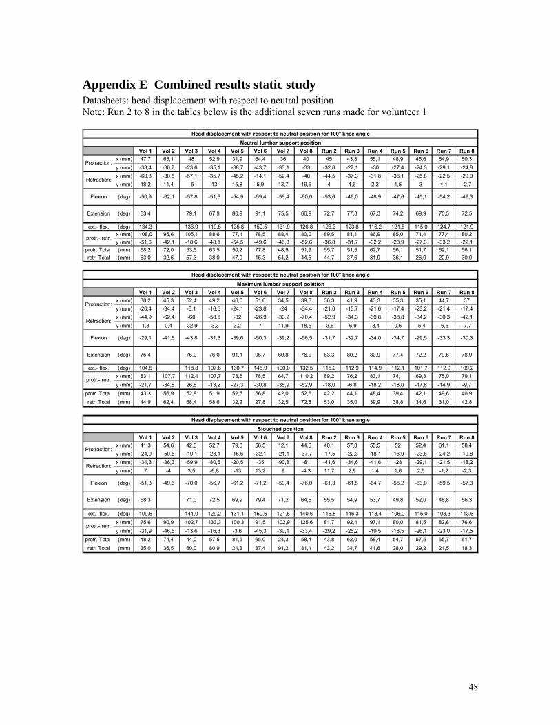
Appendix E Combined results static study Datasheets: head displacement with respect to neutral position Note: Run 2 to 8 in the tables below is the additional seven runs made for volunteer 1
Vol 1 Vol 2 Vol 3 Vol 4 Vol 5 Vol 6 Vol 7 Vol 8 Run 2 Run 3 Run 4 Run 5 Run 6 Run 7 Run 8x (mm) 47,7 65,1 48 52,9 31,9 64,4 36 40 45 43,8 55,1 48,9 45,6 54,9 50,3y (mm) -33,4 -30,7 -23,6 -35,1 -38,7 -43,7 -33,1 -33 -32,8 -27,1 -30 -27,4 -24,3 -29,1 -24,8x (mm) -60,3 -30,5 -57,1 -35,7 -45,2 -14,1 -52,4 -40 -44,5 -37,3 -31,8 -36,1 -25,8 -22,5 -29,9y (mm) 18,2 11,4 -5 13 15,8 5,9 13,7 19,6 4 4,6 2,2 1,5 3 4,1 -2,7
ext.- flex. (deg) 134,3 136,9 119,5 135,8 150,5 131,9 126,8 126,3 123,8 116,2 121,8 115,0 124,7 121,9x (mm) 108,0 95,6 105,1 88,6 77,1 78,5 88,4 80,0 89,5 81,1 86,9 85,0 71,4 77,4 80,2y (mm) -51,6 -42,1 -18,6 -48,1 -54,5 -49,6 -46,8 -52,6 -36,8 -31,7 -32,2 -28,9 -27,3 -33,2 -22,1
protr. Total (mm) 58,2 72,0 53,5 63,5 50,2 77,8 48,9 51,9 55,7 51,5 62,7 56,1 51,7 62,1 56,1retr. Total (mm) 63,0 32,6 57,3 38,0 47,9 15,3 54,2 44,5 44,7 37,6 31,9 36,1 26,0 22,9 30,0
Vol 1 Vol 2 Vol 3 Vol 4 Vol 5 Vol 6 Vol 7 Vol 8 Run 2 Run 3 Run 4 Run 5 Run 6 Run 7 Run 8x (mm) 38,2 45,3 52,4 49,2 46,6 51,6 34,5 39,8 36,3 41,9 43,3 35,3 35,1 44,7 37y (mm) -20,4 -34,4 -6,1 -16,5 -24,1 -23,8 -24 -34,4 -21,6 -13,7 -21,6 -17,4 -23,2 -21,4 -17,4x (mm) -44,9 -62,4 -60 -58,5 -32 -26,9 -30,2 -70,4 -52,9 -34,3 -39,8 -38,8 -34,2 -30,3 -42,1y (mm) 1,3 0,4 -32,9 -3,3 3,2 7 11,9 18,5 -3,6 -6,9 -3,4 0,6 -5,4 -6,5 -7,7
ext.- flex. (deg) 104,5 118,8 107,6 130,7 145,9 100,0 132,5 115,0 112,9 114,9 112,1 101,7 112,9 109,2x (mm) 83,1 107,7 112,4 107,7 78,6 78,5 64,7 110,2 89,2 76,2 83,1 74,1 69,3 75,0 79,1y (mm) -21,7 -34,8 26,8 -13,2 -27,3 -30,8 -35,9 -52,9 -18,0 -6,8 -18,2 -18,0 -17,8 -14,9 -9,7
protr. Total (mm) 43,3 56,9 52,8 51,9 52,5 56,8 42,0 52,6 42,2 44,1 48,4 39,4 42,1 49,6 40,9retr. Total (mm) 44,9 62,4 68,4 58,6 32,2 27,8 32,5 72,8 53,0 35,0 39,9 38,8 34,6 31,0 42,8
Vol 1 Vol 2 Vol 3 Vol 4 Vol 5 Vol 6 Vol 7 Vol 8 Run 2 Run 3 Run 4 Run 5 Run 6 Run 7 Run 8x (mm) 41,3 54,6 42,8 52,7 79,8 56,5 12,1 44,6 40,1 57,8 55,5 52 52,4 61,1 58,4y (mm) -24,9 -50,5 -10,1 -23,1 -16,6 -32,1 -21,1 -37,7 -17,5 -22,3 -18,1 -16,9 -23,6 -24,2 -19,8x (mm) -34,3 -36,3 -59,9 -80,6 -20,5 -35 -90,8 -81 -41,6 -34,6 -41,6 -28 -29,1 -21,5 -18,2y (mm) 7 -4 3,5 -6,8 -13 13,2 9 -4,3 11,7 2,9 1,4 1,6 2,5 -1,2 -2,3
ext.- flex. (deg) 109,6 141,0 129,2 131,1 150,6 121,5 140,6 116,8 116,3 118,4 105,0 115,0 108,3 113,6x (mm) 75,6 90,9 102,7 133,3 100,3 91,5 102,9 125,6 81,7 92,4 97,1 80,0 81,5 82,6 76,6y (mm) -31,9 -46,5 -13,6 -16,3 -3,6 -45,3 -30,1 -33,4 -29,2 -25,2 -19,5 -18,5 -26,1 -23,0 -17,5
protr. Total (mm) 48,2 74,4 44,0 57,5 81,5 65,0 24,3 58,4 43,8 62,0 58,4 54,7 57,5 65,7 61,7retr. Total (mm) 35,0 36,5 60,0 80,9 24,3 37,4 91,2 81,1 43,2 34,7 41,6 28,0 29,2 21,5 18,3
protr.- retr.
Extension
protr.- retr.
(deg)Flexion
Extension
Protraction:
Retraction:
Head displacement with respect to neutral position for 100° knee angleSlouched position
54,9(deg)
-49,6 -70,0 -56,7 -61,2 -71,2-51,3 -61,3 -61,5
53,7 49,8 52,0
-64,7
58,3 55,5
Retraction:
(deg)
(deg)
Protraction:
Flexion
Retraction:
Flexion
Maximum lumbar support position
-29,1 -31,7 -32,7-43,8 -31,6
Protraction:
77,4 78,980,2 80,9 79,6
Head displacement with respect to neutral position for 100° knee angle
-46,0 -48,9
77,8
56,3
-55,2 -63,0 -59,5 -57,3
48,8
67,3
-54,2 -49,3
70,5
-47,6
74,2 72,5
-34,0
75,4 83,3
-41,6
72,2
-29,5-34,7 -30,3-39,2
Head displacement with respect to neutral position for 100° knee angle
-50,9
83,4
-53,6
72,7
(deg)
Extension
Neutral lumbar support position
-33,3
protr.- retr.
66,9 69,9
-45,1
91,180,967,9(deg) 79,1
-60,0-56,4-59,4-54,9-51,6-57,8-62,1
75,5
-56,5
75,0 76,0 91,1 95,7 60,8 76,0
-39,6 -50,3
-76,0
71,0 72,5 69,9 79,4 71,2 64,6
-50,4
48
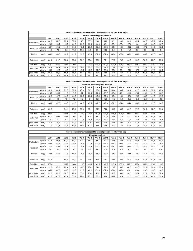
Vol 1 Vol 2 Vol 3 Vol 6 Vol 7 Vol 8 Vol 9 Vol 10 Run 2 Run 3 Run 4 Run 5 Run 6 Run 7 Run 8x (mm) 48,3 60,7 53,6 56,6 37 65,7 39 43,3 42,1 48,1 50,4 43,4 44,7 45,5 47,3y (mm) -29,3 -34,7 -15,7 -30,3 -29,8 -38,6 -44,3 -40,1 -29,9 -27,4 -27,8 -34 -28,3 -33,9 -32,5x (mm) -50,1 -25,7 -44,4 -30,2 -15,4 -23,2 -37,9 -63,3 -31,6 -30 -24,2 -33,8 -27,2 -25,5 -32,1y (mm) 11,5 7,8 -2,2 11,9 17,3 6,6 18,4 10,5 6,4 1 -1,2 3,6 1,8 3,2 -0,1
ext.- flex. (deg) 125,3 116,2 123,6 109,1 137,2 148,8 118,2 143,0 121,8 124,6 113,8 114,7 116,2 117,7 124,8x (mm) 98,4 86,4 98,0 86,8 52,4 88,9 76,9 106,6 73,7 78,1 74,6 77,2 71,9 71,0 79,4y (mm) -40,8 -42,5 -13,5 -42,2 -47,1 -45,2 -62,7 -50,6 -36,3 -28,4 -26,6 -37,6 -30,1 -37,1 -32,4
protr. Total (mm) 56,5 69,9 55,9 64,2 47,5 76,2 59,0 59,0 51,6 55,4 57,6 55,1 52,9 56,7 57,4retr. Total (mm) 51,4 26,9 44,5 32,5 23,2 24,1 42,1 64,2 32,2 30,0 24,2 34,0 27,3 25,7 32,1
Vol 1 Vol 2 Vol 3 Vol 6 Vol 7 Vol 8 Vol 9 Vol 10 Run 2 Run 3 Run 4 Run 5 Run 6 Run 7 Run 8x (mm) 36,1 66,1 71,7 39,5 43,6 51,7 37,8 30,4 40,4 36,7 34,4 41,3 38,6 39,3 40,9y (mm) -13,7 -35,2 -11,9 -17,3 -27 -30,5 -22,6 -28,7 -16,8 -15,1 -11,3 -23,2 -19,1 -22,6 -20,5x (mm) -31,9 -37,8 -34,7 -66,6 -35,5 -28,8 -45,4 -72,8 -46,4 -38 -52,6 -26,8 -33,9 -41,6 -37,5y (mm) 0,5 1,8 -15 7,2 0,2 9 10,7 15,6 -7,6 -7,1 -3,6 -5,6 -3,6 -6,1 -4,2
ext.- flex. (deg) 118,5 123,8 114,4 139,2 140,7 107,4 124,8 115,8 121,0 117,6 112,3 105,6 115,0 108,7x (mm) 68,0 103,9 106,4 106,1 79,1 80,5 83,2 103,2 86,8 74,7 87,0 68,1 72,5 80,9 78,4y (mm) -14,2 -37,0 3,1 -24,5 -27,2 -39,5 -33,3 -44,3 -9,2 -8,0 -7,7 -17,6 -15,5 -16,5 -16,3
protr. Total (mm) 38,6 74,9 72,7 43,1 51,3 60,0 44,0 41,8 43,8 39,7 36,2 47,4 43,1 45,3 45,7retr. Total (mm) 31,9 37,8 37,8 67,0 35,5 30,2 46,6 74,5 47,0 38,7 52,7 27,4 34,1 42,0 37,7
Vol 1 Vol 2 Vol 3 Vol 6 Vol 7 Vol 8 Vol 9 Vol 10 Run 2 Run 3 Run 4 Run 5 Run 6 Run 7 Run 8x (mm) 47,5 46,1 51,7 69,7 79,7 63,3 43,3 31,7 35,6 52,6 52,1 50,6 47 40,3 49,5y (mm) -28,8 -41,9 -23,3 -19,2 -10,6 -31,3 -20,4 -28,3 -22,2 -19,4 -22 -17,1 -21,3 -33,4 -16,9x (mm) -45 -40,9 -37,7 -33 -25,1 -27,5 -20,7 -96,3 -44,3 -32,4 -32,5 -33 -32,5 -46,5 -31,3y (mm) 6,4 5,9 22,5 6,3 11 8,8 11,2 9,5 8,8 -0,6 1,1 1,3 -5 -5,1 -0,6
Ext.- Flex. (deg) 108,4 135,7 133,4 129,0 145,1 103,9 145,5 113,6 108,0 112,7 108,4 118,3 120,9 114,6x (mm) 92,5 87,0 89,4 102,7 104,8 90,8 64,0 128,0 79,9 85,0 84,6 83,6 79,5 86,8 80,8y (mm) -35,2 -47,8 -45,8 -25,5 -21,6 -40,1 -31,6 -37,8 -31,0 -18,8 -23,1 -18,4 -16,3 -28,3 -16,3
protr. Total (mm) 55,5 62,3 56,7 72,3 80,4 70,6 47,9 42,5 42,0 56,1 56,6 53,4 51,6 52,3 52,3retr. Total (mm) 45,5 41,3 43,9 33,6 27,4 28,9 23,5 96,8 45,2 32,4 32,5 33,0 32,9 46,8 31,3
protr.- retr.
Extension
protr.- retr.
(deg)Flexion
Extension
Protraction:
Retraction:
Head displacement with respect to neutral position for 145° knee angleSlouched position
55,4(deg)
-65,6 -71,5 -66,7 -70,2 -78,5-52,6 -64,2 -52,6
54,1 55,7 57,2
-58,6
55,7 49,4
Retraction:
(deg)
(deg)
Protraction:
Flexion
Retraction:
Flexion
Maximum lumbar support position
-36,0 -31,2 -34,0-49,8 -35,8
Protraction:
77,5 81,886,9 83,6 82,7
Head displacement with respect to neutral position for 145° knee angle
-50,8 -45,3
73,9
58,7
-52,7 -61,1 -59,0 -55,8
61,9
68,5
-47,0 -48,3
70,7
-48,8
65,8 76,5
-34,0
82,5 84,6
-47,0
76,5
-29,1-34,9 -26,9-42,7
Head displacement with respect to neutral position for 145° knee angle
-44,9
80,4
-49,8
72,0
(deg)
Extension
Neutral lumbar support position
-32,3
protr.- retr.
75,1 70,2
-45,9
83,881,756,4(deg) 70,961,7
-67,8-52,9-65,0-55,5-52,7-52,7-54,5
65,3
-49,3
74,1 78,6 92,6 97,1 64,7 75,5
-46,6 -43,5
-69,8
64,2 66,7 58,7 66,6 45,4 75,7
-58,6
49
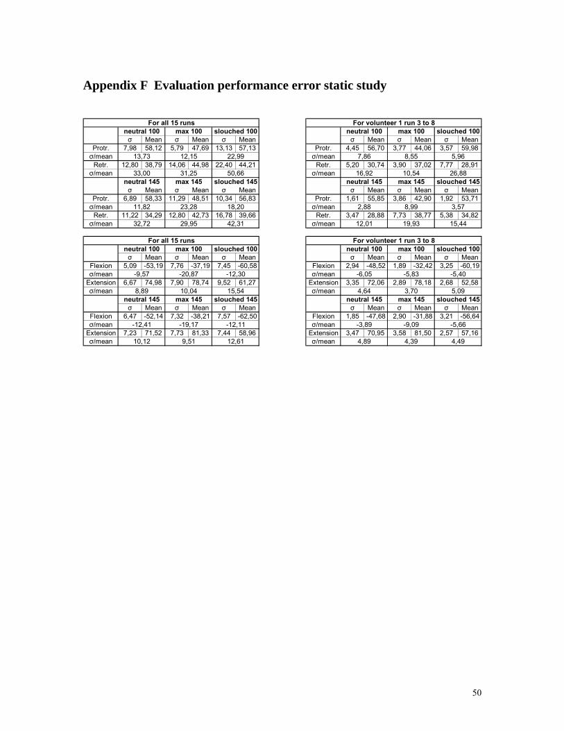
Appendix F Evaluation performance error static study
σ Mean σ Mean σ Mean σ Mean σ Mean σ MeanProtr. 7,98 58,12 5,79 47,69 13,13 57,13 Protr. 4,45 56,70 3,77 44,06 3,57 59,98σ/mean σ/mean
Retr. 12,80 38,79 14,06 44,98 22,40 44,21 Retr. 5,20 30,74 3,90 37,02 7,77 28,91σ/mean σ/mean
σ Mean σ Mean σ Mean σ Mean σ Mean σ MeanProtr. 6,89 58,33 11,29 48,51 10,34 56,83 Protr. 1,61 55,85 3,86 42,90 1,92 53,71σ/mean σ/mean
Retr. 11,22 34,29 12,80 42,73 16,78 39,66 Retr. 3,47 28,88 7,73 38,77 5,38 34,82σ/mean σ/mean
σ Mean σ Mean σ Mean σ Mean σ Mean σ MeanFlexion 5,09 -53,19 7,76 -37,19 7,45 -60,58 Flexion 2,94 -48,52 1,89 -32,42 3,25 -60,19σ/mean σ/mean
Extension 6,67 74,98 7,90 78,74 9,52 61,27 Extension 3,35 72,06 2,89 78,18 2,68 52,58σ/mean σ/mean
σ Mean σ Mean σ Mean σ Mean σ Mean σ MeanFlexion 6,47 -52,14 7,32 -38,21 7,57 -62,50 Flexion 1,85 -47,68 2,90 -31,88 3,21 -56,64σ/mean σ/mean
Extension 7,23 71,52 7,73 81,33 7,44 58,96 Extension 3,47 70,95 3,58 81,50 2,57 57,16σ/mean σ/mean
-3,89 -9,09 -5,66
4,89 4,39 4,49
4,64 3,70 5,09neutral 145 max 145 slouched 145
neutral 100 max 100 slouched 100
-6,05 -5,83 -5,40
12,01 19,93 15,44
For volunteer 1 run 3 to 8
neutral 145 max 145 slouched 145
2,88 8,99 3,57
7,86 8,55 5,96
16,92 10,54 26,88
For volunteer 1 run 3 to 8neutral 100 max 100 slouched 100
-12,41 -19,17 -12,11
10,12 9,51 12,61
8,89 10,04 15,54neutral 145 max 145 slouched 145
neutral 100 max 100 slouched 100
-9,57 -20,87 -12,30
32,72 29,95 42,31
For all 15 runs
neutral 145 max 145 slouched 145
11,82 23,28 18,20
13,73 12,15 22,99
33,00 31,25 50,66
For all 15 runsneutral 100 max 100 slouched 100
50
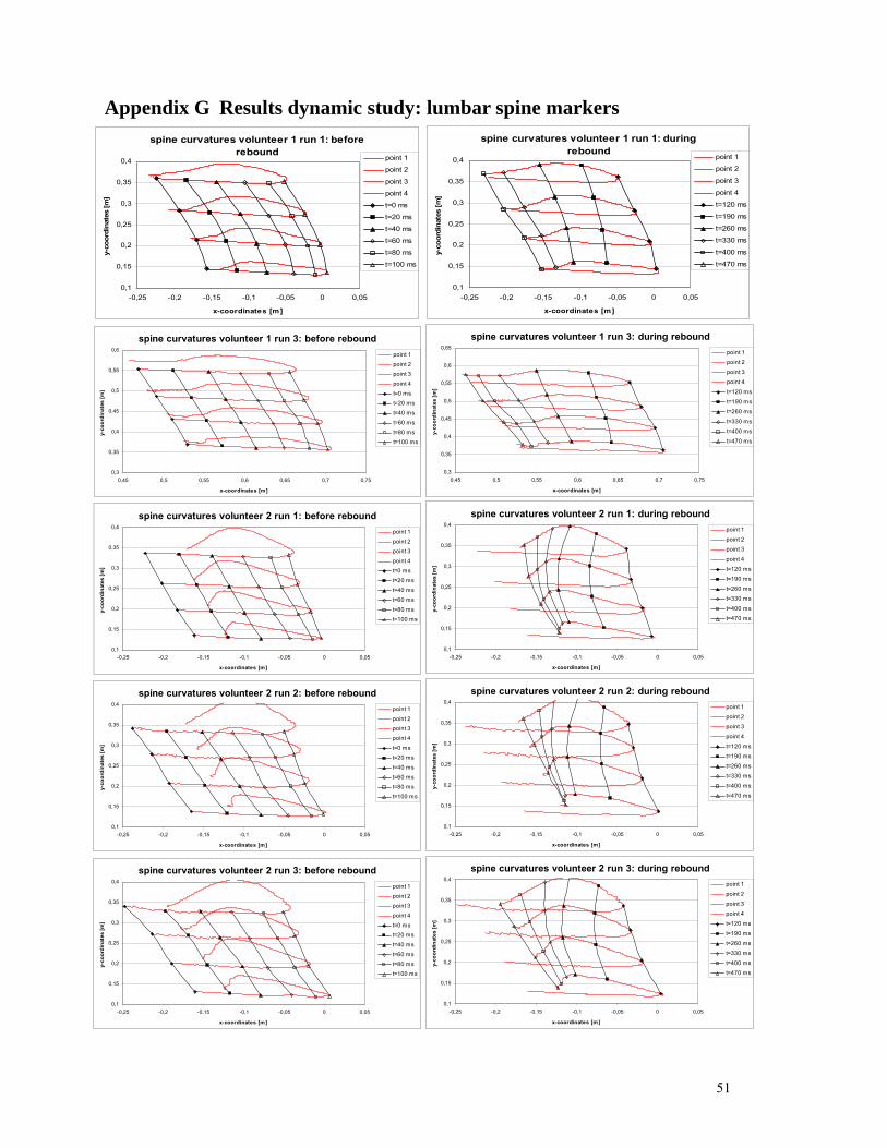
Appendix G Results dynamic study: lumbar spine markers spine curvatures volunteer 1 run 1: before
rebound
0,1
0,15
0,2
0,25
0,3
0,35
0,4
-0,25 -0,2 -0,15 -0,1 -0,05 0 0,05
x-coordinates [m]
y-co
ordi
nate
s [m
]
point 1
point 2
point 3
point 4
t=0 ms
t=20 ms
t=40 ms
t=60 ms
t=80 ms
t=100 ms
spine curvatures volunteer 1 run 1: during rebound
0,1
0,15
0,2
0,25
0,3
0,35
0,4
-0,25 -0,2 -0,15 -0,1 -0,05 0 0,05
x-coordinates [m]
y-co
ordi
nate
s [m
]
point 1
point 2
point 3
point 4
t=120 ms
t=190 ms
t=260 ms
t=330 ms
t=400 ms
t=470 ms
spine curvatures volunteer 1 run 3: before rebound
0,3
0,35
0,4
0,45
0,5
0,55
0,6
0,45 0,5 0,55 0,6 0,65 0,7 0,75
x-coordinates [m]
y-co
ordi
nate
s [m
]
point 1
point 2point 3
point 4
t=0 mst=20 ms
t=40 ms
t=60 ms
t=80 mst=100 ms
spine curvatures volunteer 1 run 3: during rebound
0,3
0,35
0,4
0,45
0,5
0,55
0,6
0,65
0,45 0,5 0,55 0,6 0,65 0,7 0,75
x-coordinates [m]
y-co
ordi
nate
s [m
]
point 1point 2
point 3point 4
t=120 mst=190 mst=260 ms
t=330 mst=400 ms
t=470 ms
spine curvatures volunteer 2 run 1: before rebound
0,1
0,15
0,2
0,25
0,3
0,35
0,4
-0,25 -0,2 -0,15 -0,1 -0,05 0 0,05
x-coordinates [m]
y-co
ordi
nate
s [m
]
point 1
point 2point 3
point 4
t=0 mst=20 ms
t=40 ms
t=60 ms
t=80 mst=100 ms
spine curvatures volunteer 2 run 1: during rebound
0,1
0,15
0,2
0,25
0,3
0,35
0,4
-0,25 -0,2 -0,15 -0,1 -0,05 0 0,05
x-coordinates [m]
y-co
ordi
nate
s [m
]
point 1
point 2point 3
point 4t=120 mst=190 ms
t=260 mst=330 ms
t=400 mst=470 ms
spine curvatures volunteer 2 run 2: before rebound
0,1
0,15
0,2
0,25
0,3
0,35
0,4
-0,25 -0,2 -0,15 -0,1 -0,05 0 0,05
x-coordinates [m]
y-co
ordi
nate
s [m
]
point 1
point 2point 3
point 4
t=0 mst=20 ms
t=40 ms
t=60 ms
t=80 mst=100 ms
spine curvatures volunteer 2 run 2: during rebound
0,1
0,15
0,2
0,25
0,3
0,35
0,4
-0,25 -0,2 -0,15 -0,1 -0,05 0 0,05
x-coordinates [m]
y-co
ordi
nate
s [m
]
point 1point 2
point 3point 4
t=120 mst=190 mst=260 ms
t=330 mst=400 ms
t=470 ms
spine curvatures volunteer 2 run 3: before rebound
0,1
0,15
0,2
0,25
0,3
0,35
0,4
-0,25 -0,2 -0,15 -0,1 -0,05 0 0,05
x-coordinates [m]
y-co
ordi
nate
s [m
]
point 1
point 2point 3
point 4
t=0 mst=20 ms
t=40 ms
t=60 ms
t=80 mst=100 ms
spine curvatures volunteer 2 run 3: during rebound
0,1
0,15
0,2
0,25
0,3
0,35
0,4
-0,25 -0,2 -0,15 -0,1 -0,05 0 0,05
x-coordinates [m]
y-co
ordi
nate
s [m
]
point 1
point 2point 3
point 4t=120 mst=190 ms
t=260 mst=330 ms
t=400 mst=470 ms
51
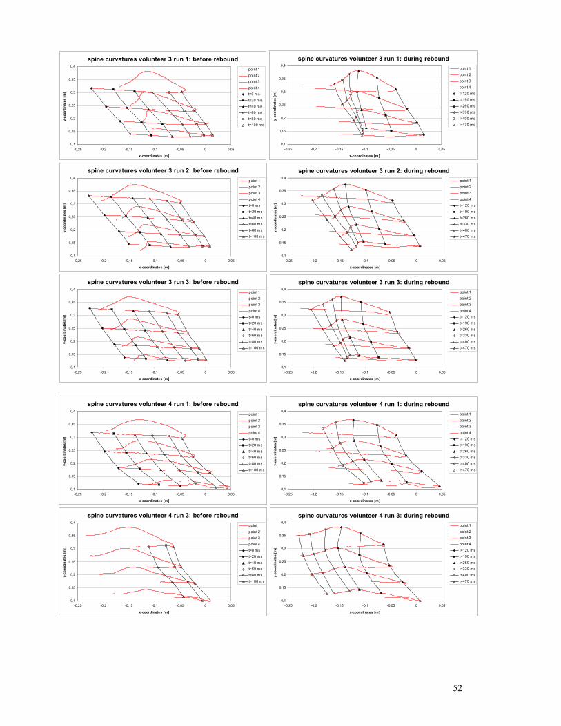
spine curvatures volunteer 3 run 1: before rebound
0,1
0,15
0,2
0,25
0,3
0,35
0,4
-0,25 -0,2 -0,15 -0,1 -0,05 0 0,05
x-coordinates [m]
y-co
ordi
nate
s [m
]point 1point 2
point 3point 4
t=0 mst=20 ms
t=40 mst=60 mst=80 ms
t=100 ms
spine curvatures volunteer 3 run 1: during rebound
0,1
0,15
0,2
0,25
0,3
0,35
0,4
-0,25 -0,2 -0,15 -0,1 -0,05 0 0,05
x-coordinates [m]
y-co
ordi
nate
s [m
]
point 1point 2
point 3point 4
t=120 mst=190 mst=260 ms
t=330 mst=400 ms
t=470 ms
spine curvatures volunteer 3 run 2: before rebound
0,1
0,15
0,2
0,25
0,3
0,35
0,4
-0,25 -0,2 -0,15 -0,1 -0,05 0 0,05
x-coordinates [m]
y-co
ordi
nate
s [m
]
point 1point 2
point 3point 4
t=0 mst=20 ms
t=40 mst=60 mst=80 ms
t=100 ms
spine curvatures volunteer 3 run 2: during rebound
0,1
0,15
0,2
0,25
0,3
0,35
0,4
-0,25 -0,2 -0,15 -0,1 -0,05 0 0,05
x-coordinates [m]
y-co
ordi
nate
s [m
]
point 1point 2
point 3
point 4t=120 ms
t=190 ms
t=260 mst=330 ms
t=400 ms
t=470 ms
spine curvatures volunteer 3 run 3: before rebound
0,1
0,15
0,2
0,25
0,3
0,35
0,4
-0,25 -0,2 -0,15 -0,1 -0,05 0 0,05
x-coordinates [m]
y-co
ordi
nate
s [m
]
point 1point 2
point 3point 4
t=0 mst=20 ms
t=40 mst=60 mst=80 ms
t=100 ms
spine curvatures volunteer 3 run 3: during rebound
0,1
0,15
0,2
0,25
0,3
0,35
0,4
-0,25 -0,2 -0,15 -0,1 -0,05 0 0,05
x-coordinates [m]
y-co
ordi
nate
s [m
]
point 1point 2
point 3
point 4t=120 ms
t=190 ms
t=260 mst=330 ms
t=400 ms
t=470 ms
spine curvatures volunteer 4 run 1: before rebound
0,1
0,15
0,2
0,25
0,3
0,35
0,4
-0,25 -0,2 -0,15 -0,1 -0,05 0 0,05
x-coordinates [m]
y-co
ordi
nate
s [m
]
point 1point 2
point 3point 4
t=0 mst=20 ms
t=40 mst=60 mst=80 ms
t=100 ms
spine curvatures volunteer 4 run 1: during rebound
0,1
0,15
0,2
0,25
0,3
0,35
0,4
-0,25 -0,2 -0,15 -0,1 -0,05 0 0,05
x-coordinates [m]
y-co
ordi
nate
s [m
]
point 1
point 2point 3
point 4
t=120 mst=190 ms
t=260 ms
t=330 ms
t=400 mst=470 ms
spine curvatures volunteer 4 run 3: before rebound
0,1
0,15
0,2
0,25
0,3
0,35
0,4
-0,25 -0,2 -0,15 -0,1 -0,05 0 0,05
x-coordinates [m]
y-co
ordi
nate
s [m
]
point 1point 2
point 3point 4
t=0 mst=20 ms
t=40 mst=60 mst=80 ms
t=100 ms
spine curvatures volunteer 4 run 3: during rebound
0,1
0,15
0,2
0,25
0,3
0,35
0,4
-0,25 -0,2 -0,15 -0,1 -0,05 0 0,05
x-coordinates [m]
y-co
ordi
nate
s [m
]
point 1
point 2point 3
point 4
t=120 mst=190 ms
t=260 ms
t=330 ms
t=400 mst=470 ms
52
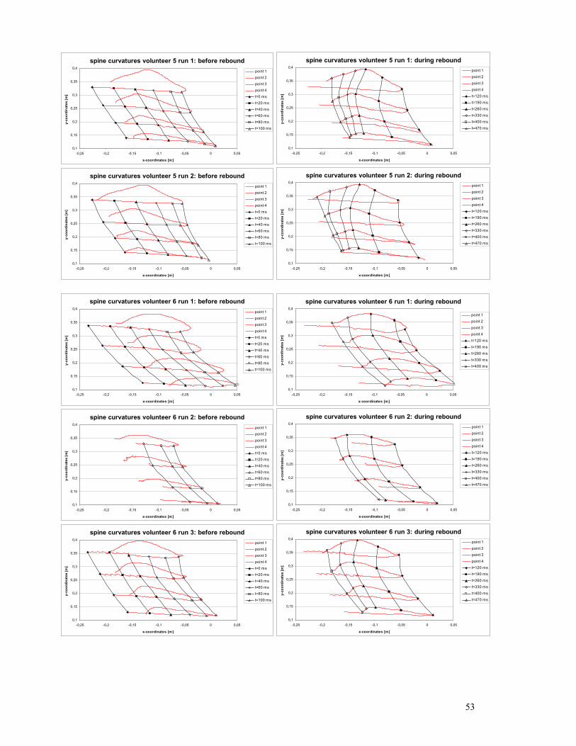
spine curvatures volunteer 5 run 1: before rebound
0,1
0,15
0,2
0,25
0,3
0,35
0,4
-0,25 -0,2 -0,15 -0,1 -0,05 0 0,05
x-coordinates [m]
y-co
ordi
nate
s [m
]point 1point 2
point 3point 4
t=0 mst=20 ms
t=40 mst=60 mst=80 ms
t=100 ms
spine curvatures volunteer 5 run 1: during rebound
0,1
0,15
0,2
0,25
0,3
0,35
0,4
-0,25 -0,2 -0,15 -0,1 -0,05 0 0,05
x-coordinates [m]
y-co
ordi
nate
s [m
]
point 1point 2
point 3point 4
t=120 mst=190 mst=260 ms
t=330 mst=400 ms
t=470 ms
spine curvatures volunteer 5 run 2: before rebound
0,1
0,15
0,2
0,25
0,3
0,35
0,4
-0,25 -0,2 -0,15 -0,1 -0,05 0 0,05
x-coordinates [m]
y-co
ordi
nate
s [m
]
point 1point 2
point 3point 4
t=0 mst=20 ms
t=40 mst=60 mst=80 ms
t=100 ms
spine curvatures volunteer 5 run 2: during rebound
0,1
0,15
0,2
0,25
0,3
0,35
0,4
-0,25 -0,2 -0,15 -0,1 -0,05 0 0,05
x-coordinates [m]
y-co
ordi
nate
s [m
]
point 1
point 2point 3
point 4t=120 mst=190 ms
t=260 mst=330 ms
t=400 mst=470 ms
spine curvatures volunteer 6 run 1: before rebound
0,1
0,15
0,2
0,25
0,3
0,35
0,4
-0,25 -0,2 -0,15 -0,1 -0,05 0 0,05
x-coordinates [m]
y-co
ordi
nate
s [m
]
point 1point 2point 3
point 4t=0 mst=20 mst=40 ms
t=60 mst=80 mst=100 ms
spine curvatures volunteer 6 run 1: during rebound
0,1
0,15
0,2
0,25
0,3
0,35
0,4
-0,25 -0,2 -0,15 -0,1 -0,05 0 0,05
x-coordinates [m]
y-co
ordi
nate
s [m
]
point 1point 2
point 3point 4t=120 ms
t=190 mst=260 ms
t=330 mst=400 ms
spine curvatures volunteer 6 run 2: before rebound
0,1
0,15
0,2
0,25
0,3
0,35
0,4
-0,25 -0,2 -0,15 -0,1 -0,05 0 0,05
x-coordinates [m]
y-co
ordi
nate
s [m
]
point 1point 2
point 3point 4
t=0 mst=20 ms
t=40 mst=60 mst=80 ms
t=100 ms
spine curvatures volunteer 6 run 2: during rebound
0,1
0,15
0,2
0,25
0,3
0,35
0,4
-0,25 -0,2 -0,15 -0,1 -0,05 0 0,05
x-coordinates [m]
y-co
ordi
nate
s [m
]
point 1point 2
point 3point 4
t=120 mst=190 mst=260 ms
t=330 mst=400 ms
t=470 ms
spine curvatures volunteer 6 run 3: before rebound
0,1
0,15
0,2
0,25
0,3
0,35
0,4
-0,25 -0,2 -0,15 -0,1 -0,05 0 0,05
x-coordinates [m]
y-co
ordi
nate
s [m
]
point 1point 2
point 3point 4
t=0 mst=20 ms
t=40 mst=60 mst=80 ms
t=100 ms
spine curvatures volunteer 6 run 3: during rebound
0,1
0,15
0,2
0,25
0,3
0,35
0,4
-0,25 -0,2 -0,15 -0,1 -0,05 0 0,05
x-coordinates [m]
y-co
ordi
nate
s [m
]
point 1
point 2point 3
point 4t=120 mst=190 ms
t=260 mst=330 ms
t=400 mst=470 ms
53
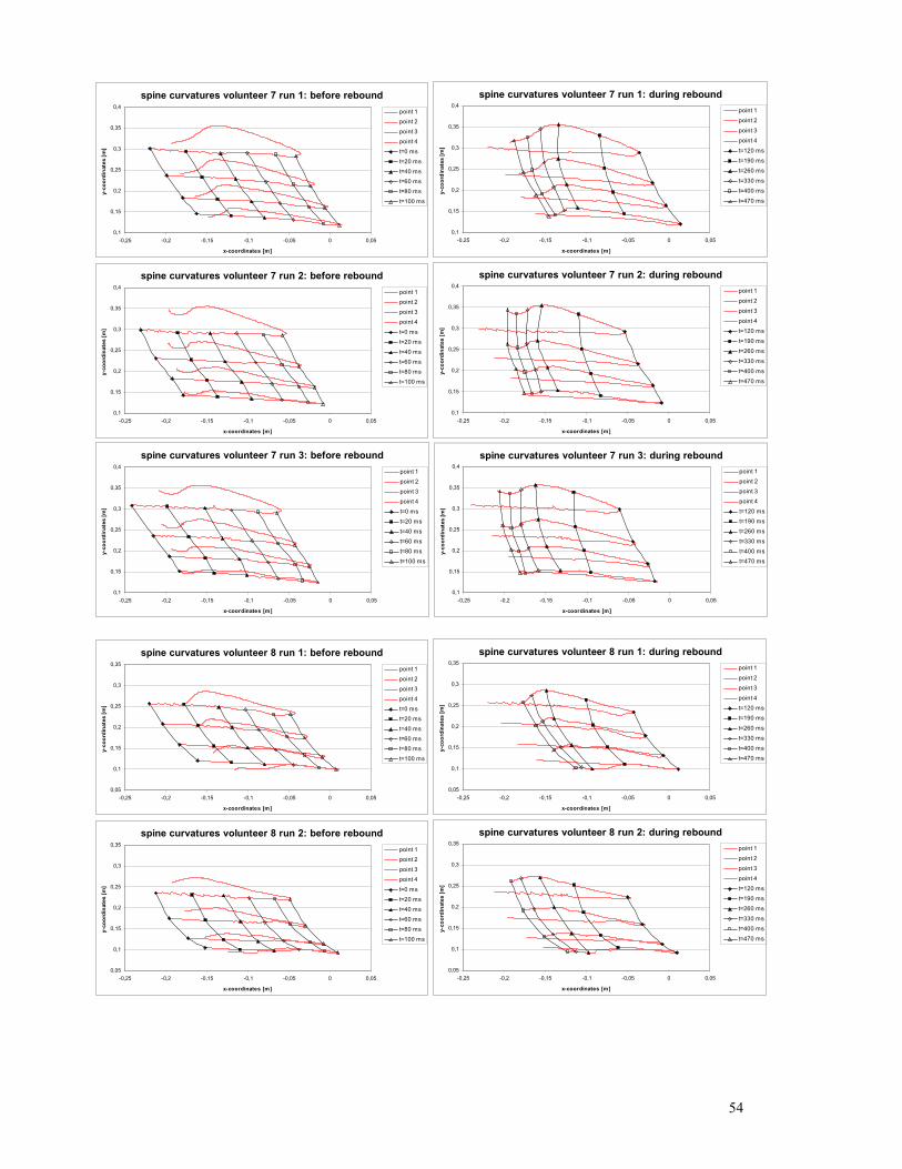
spine curvatures volunteer 7 run 1: before rebound
0,1
0,15
0,2
0,25
0,3
0,35
0,4
-0,25 -0,2 -0,15 -0,1 -0,05 0 0,05
x-coordinates [m]
y-co
ordi
nate
s [m
]point 1point 2
point 3point 4
t=0 mst=20 ms
t=40 mst=60 mst=80 ms
t=100 ms
spine curvatures volunteer 7 run 1: during rebound
0,1
0,15
0,2
0,25
0,3
0,35
0,4
-0,25 -0,2 -0,15 -0,1 -0,05 0 0,05
x-coordinates [m]
y-co
ordi
nate
s [m
]
point 1point 2
point 3point 4
t=120 mst=190 mst=260 ms
t=330 mst=400 ms
t=470 ms
spine curvatures volunteer 7 run 2: before rebound
0,1
0,15
0,2
0,25
0,3
0,35
0,4
-0,25 -0,2 -0,15 -0,1 -0,05 0 0,05
x-coordinates [m]
y-co
ordi
nate
s [m
]
point 1point 2
point 3point 4
t=0 mst=20 ms
t=40 mst=60 mst=80 ms
t=100 ms
spine curvatures volunteer 7 run 2: during rebound
0,1
0,15
0,2
0,25
0,3
0,35
0,4
-0,25 -0,2 -0,15 -0,1 -0,05 0 0,05
x-coordinates [m]
y-co
ordi
nate
s [m
]
point 1
point 2point 3
point 4t=120 mst=190 ms
t=260 mst=330 ms
t=400 mst=470 ms
spine curvatures volunteer 7 run 3: before rebound
0,1
0,15
0,2
0,25
0,3
0,35
0,4
-0,25 -0,2 -0,15 -0,1 -0,05 0 0,05
x-coordinates [m]
y-co
ordi
nate
s [m
]
point 1point 2
point 3point 4
t=0 mst=20 ms
t=40 mst=60 mst=80 ms
t=100 ms
spine curvatures volunteer 7 run 3: during rebound
0,1
0,15
0,2
0,25
0,3
0,35
0,4
-0,25 -0,2 -0,15 -0,1 -0,05 0 0,05
x-coordinates [m]
y-co
ordi
nate
s [m
]
point 1
point 2point 3
point 4
t=120 mst=190 ms
t=260 ms
t=330 ms
t=400 mst=470 ms
spine curvatures volunteer 8 run 1: before rebound
0,05
0,1
0,15
0,2
0,25
0,3
0,35
-0,25 -0,2 -0,15 -0,1 -0,05 0 0,05
x-coordinates [m]
y-co
ordi
nate
s [m
]
point 1point 2
point 3point 4
t=0 mst=20 ms
t=40 mst=60 mst=80 ms
t=100 ms
spine curvatures volunteer 8 run 1: during rebound
0,05
0,1
0,15
0,2
0,25
0,3
0,35
-0,25 -0,2 -0,15 -0,1 -0,05 0 0,05
x-coordinates [m]
y-co
ordi
nate
s [m
]
point 1
point 2point 3
point 4t=120 mst=190 ms
t=260 mst=330 ms
t=400 mst=470 ms
spine curvatures volunteer 8 run 2: before rebound
0,05
0,1
0,15
0,2
0,25
0,3
0,35
-0,25 -0,2 -0,15 -0,1 -0,05 0 0,05
x-coordinates [m]
y-co
ordi
nate
s [m
]
point 1point 2
point 3point 4
t=0 mst=20 ms
t=40 mst=60 mst=80 ms
t=100 ms
spine curvatures volunteer 8 run 2: during rebound
0,05
0,1
0,15
0,2
0,25
0,3
0,35
-0,25 -0,2 -0,15 -0,1 -0,05 0 0,05
x-coordinates [m]
y-co
ordi
nate
s [m
]
point 1point 2
point 3point 4
t=120 mst=190 mst=260 ms
t=330 mst=400 ms
t=470 ms
54
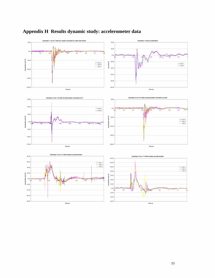
Appendix H Results dynamic study: accelerometer data
volunteer 1 run 5-7 with acc.meter mounted on sled seat frame
-200,00
-150,00
-100,00
-50,00
0,00
50,00
0 0,1 0,2 0,3 0,4 0,5 0,6 0,7 0,8
Time (s)
Acc
eler
atio
n (m
/s^2
)
Run 5Run 6Run 7
volunteer 1 knee acceleration
-100,00
-80,00
-60,00
-40,00
-20,00
0,00
20,00
40,00
0,2 0,3 0,4 0,5 0,6 0,7 0,8 0,9 1
Time (s)
Acc
(m/s
^2)
Run 1Run 2
volunteer 2 run 1-2 with accelerometer mounted at T1
-150,00
-100,00
-50,00
0,00
50,00
100,00
150,00
0,25 0,35 0,45 0,55 0,65 0,75 0,85 0,95
Time (s)
Acc
eler
atio
n (m
/s^2
)
Run 1Run 2
volunteer 2 run 3-5 with accelerometer mounted on sled
-200,00
-150,00
-100,00
-50,00
0,00
50,00
0,2 0,3 0,4 0,5 0,6 0,7 0,8 0,9 1
Time (s)
Acc
eler
atio
n (m
/s^2
)
Run 3Run 4Run 5
Volunteer 3 run 1-3 with lumbar accelerometer
-80,00
-60,00
-40,00
-20,00
0,00
20,00
40,00
60,00
80,00
0,3 0,4 0,5 0,6 0,7 0,8 0,9 1 1,1
Time (s)
Acc
eler
atio
n (m
/s^2
)
Run 1Run 2Run 3
volunteer 4 run 1-3 with lumbar accelerometer
-60,00
-40,00
-20,00
0,00
20,00
40,00
60,00
80,00
100,00
120,00
140,00
0,4 0,5 0,6 0,7 0,8 0,9 1 1,1 1,2
Time (s)
Acc
eler
atio
n (m
/s^2
)
Run 1Run 2Run 3
55
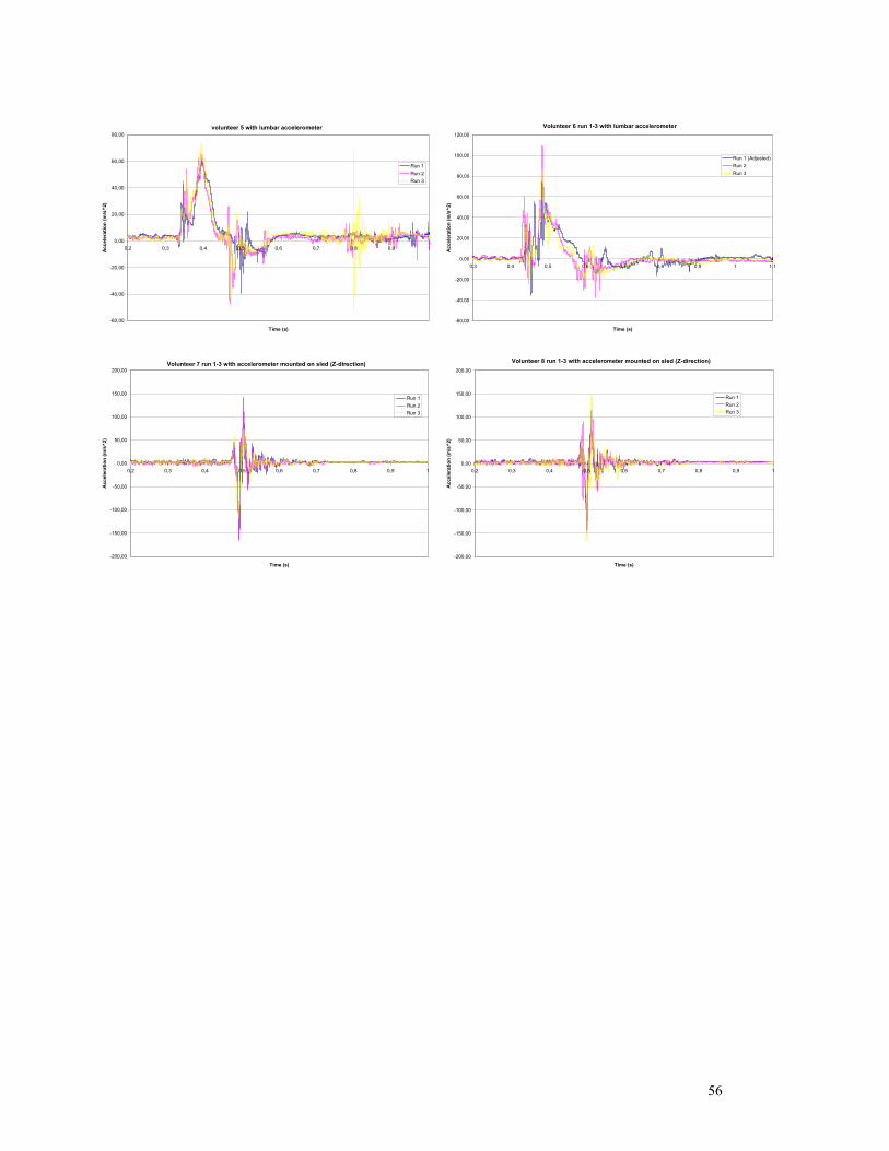
volunteer 5 with lumbar accelerometer
-60,00
-40,00
-20,00
0,00
20,00
40,00
60,00
80,00
0,2 0,3 0,4 0,5 0,6 0,7 0,8 0,9 1
Time (s)
Acc
eler
atio
n (m
/s^2
)
Run 1Run 2Run 3
Volunteer 6 run 1-3 with lumbar accelerometer
-60,00
-40,00
-20,00
0,00
20,00
40,00
60,00
80,00
100,00
120,00
0,3 0,4 0,5 0,6 0,7 0,8 0,9 1 1,1
Time (s)
Acc
eler
atio
n (m
/s^2
)
Run 1 (Adjusted)Run 2Run 3
Volunteer 7 run 1-3 with accelerometer mounted on sled (Z-direction)
-200,00
-150,00
-100,00
-50,00
0,00
50,00
100,00
150,00
200,00
0,2 0,3 0,4 0,5 0,6 0,7 0,8 0,9 1
Time (s)
Acc
eler
atio
n (m
/s^2
)
Run 1Run 2Run 3
Volunteer 8 run 1-3 with accelerometer mounted on sled (Z-direction)
-200,00
-150,00
-100,00
-50,00
0,00
50,00
100,00
150,00
200,00
0,2 0,3 0,4 0,5 0,6 0,7 0,8 0,9 1
Time (s)
Acc
eler
atio
n (m
/s^2
)
Run 1Run 2Run 3
56