Embed Size (px)
Citation preview
• Introduction to Torsion(扭转简介)
• Examples of Torsion Shafts(扭转轴示例)
• Sign Convention of Torque(扭矩符号规则)
• Torque Diagram(扭矩图)
• Power & Torque(功率与扭矩)
• Internal Torque & Stress - Static Indeterminacy(内力扭矩和应力-超静定概念的引入)
• General Relations Involved in Deformable Solids(分析可变形固体的几大基本关系)
• Kinematics(几何关系)
• Hooke’s Law for Shearing Deformation(剪切变形物理关系)
• Static Equivalency(静力等效关系)
• Torsional Stress & Angle of Twist(圆轴扭转的应力与扭转角)
Contents
2
• Nonuniform Torsion of Circular Shafts(圆轴的非均匀扭转)
• Strength & Stiffness Analysis(强度和刚度条件)
• Strain Energy and its Density(扭转应变能与应变能密度)
• Polar Moments of Inertia & Section Modulus(圆截面的极惯性矩与扭转截面系数)
• Theorem of Conjugate Shearing Stress(切应力互等定理)
• Stresses on Oblique Cross Sections(扭转轴斜截面上的应力)
• Failure Modes of Torsional Shafts(扭转轴的失效模式)
• Stress Concentrations(扭转轴的应力集中)
• Torsion of Noncircular Members(非圆截面杆的扭转)
• Membrane Analogy(薄膜比拟)
• Torsion of Thin-walled Open Shafts(薄壁开口截面杆的扭转)
• Torsion of Thin-walled Hollow Shafts(薄壁空心截面杆的扭转)
Contents
3
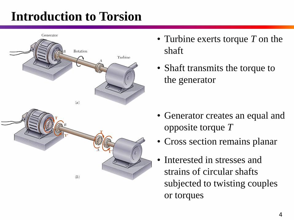
• Interested in stresses and
strains of circular shafts
subjected to twisting couples
or torques
• Generator creates an equal and
opposite torque T
• Cross section remains planar
• Turbine exerts torque T on the
shaft
Introduction to Torsion
• Shaft transmits the torque to
the generator
4
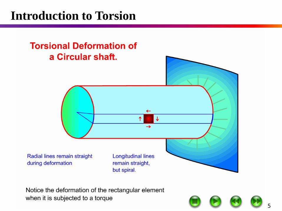
Introduction to Torsion
5
6
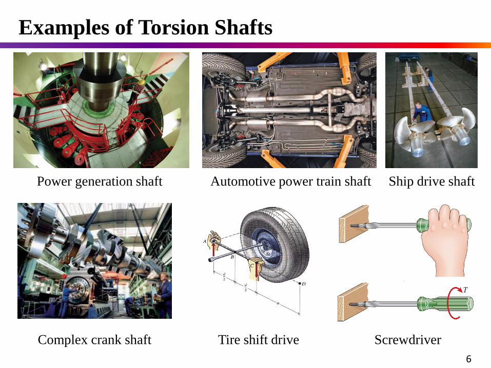
Ship drive shaft
Complex crank shaft
Automotive power train shaft
Screwdriver
Power generation shaft
Tire shift drive
Examples of Torsion Shafts
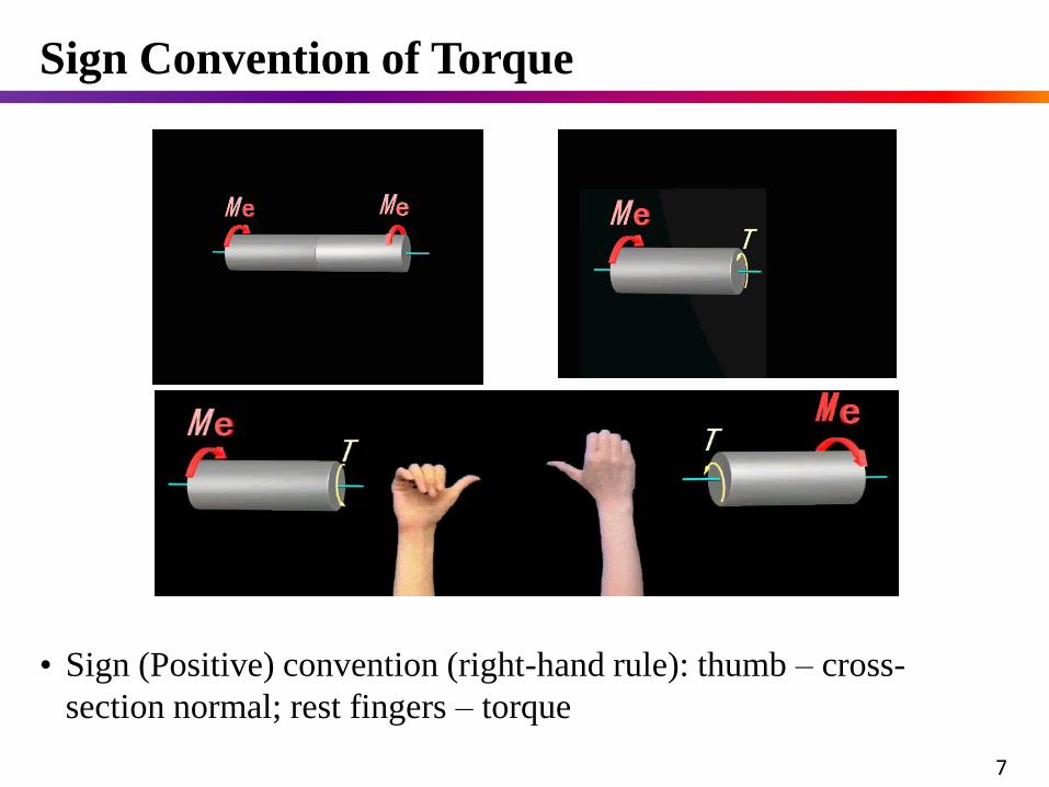
• Sign (Positive) convention (right-hand rule): thumb – cross-
section normal; rest fingers – torque
Sign Convention of Torque
7
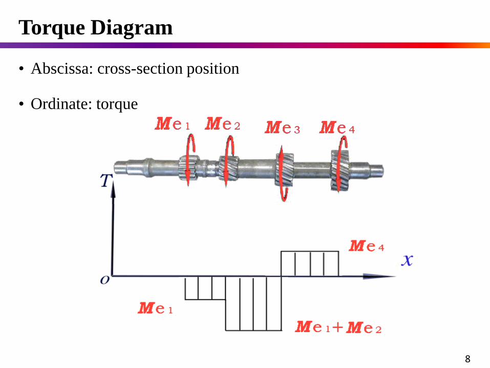
• Abscissa: cross-section position
• Ordinate: torque
Torque Diagram
8
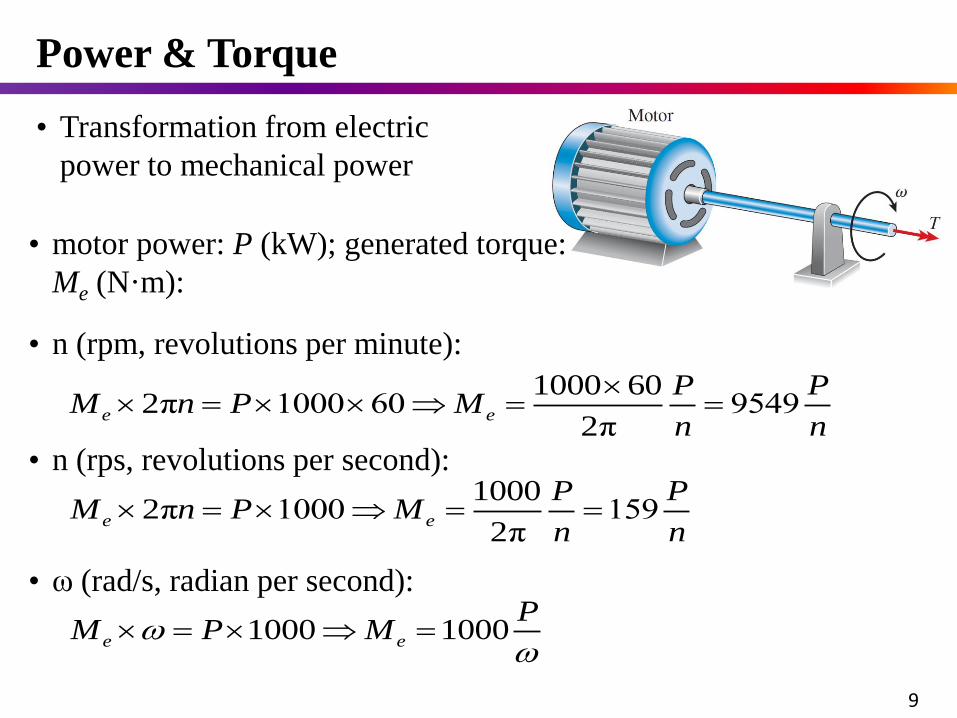
• Transformation from electric
power to mechanical power
Power & Torque
9
1000 602π 1000 60 9549
2πe e
P PM n P M
n n
• motor power: P (kW); generated torque:
Me (N·m):
• n (rpm, revolutions per minute):
10002π 1000 159
2πe e
P PM n P M
n n
1000 1000e e
PM P M
• n (rps, revolutions per second):
• ω (rad/s, radian per second):
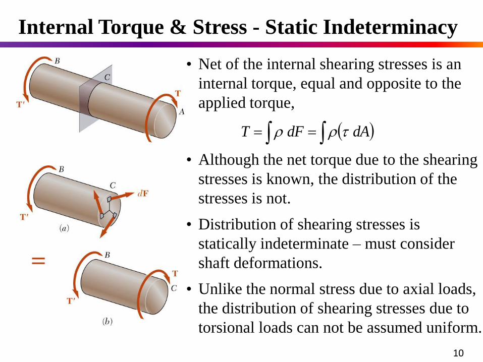
dAdFT
• Net of the internal shearing stresses is an
internal torque, equal and opposite to the
applied torque,
• Although the net torque due to the shearing
stresses is known, the distribution of the
stresses is not.
• Unlike the normal stress due to axial loads,
the distribution of shearing stresses due to
torsional loads can not be assumed uniform.
• Distribution of shearing stresses is
statically indeterminate – must consider
shaft deformations.
Internal Torque & Stress - Static Indeterminacy
10
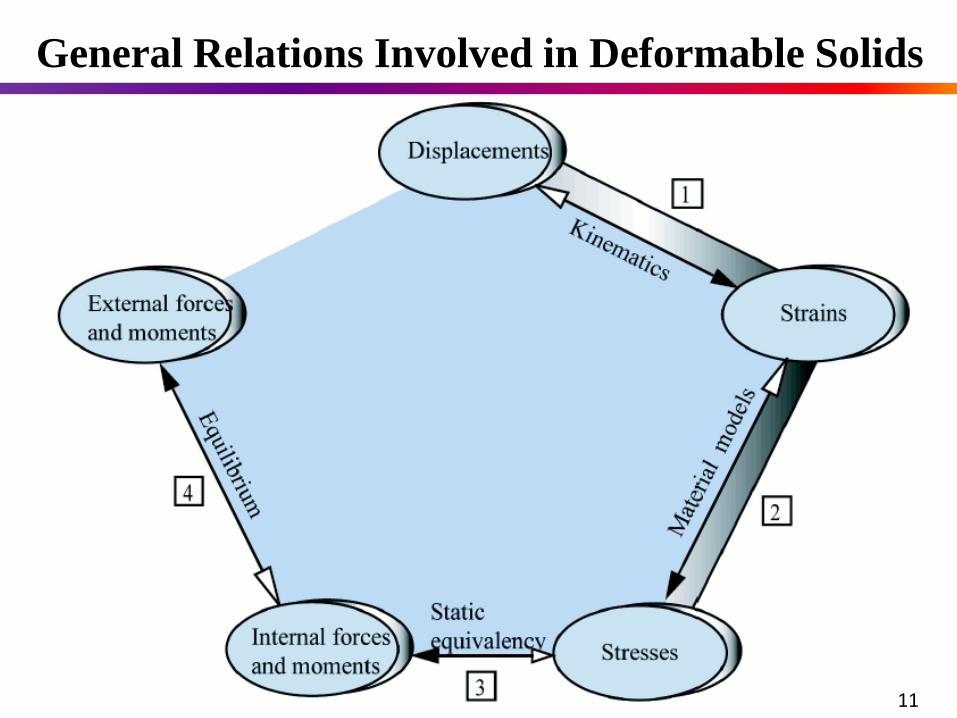
General Relations Involved in Deformable Solids
11
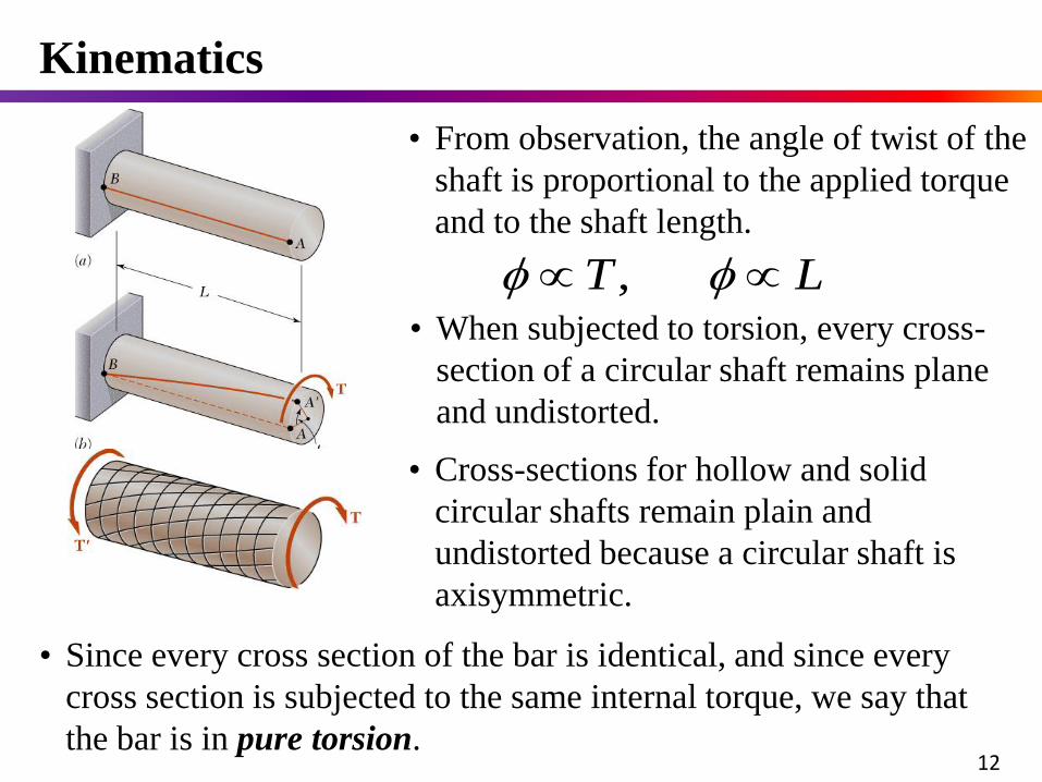
• From observation, the angle of twist of the
shaft is proportional to the applied torque
and to the shaft length.
LT ,• When subjected to torsion, every cross-
section of a circular shaft remains plane
and undistorted.
• Cross-sections for hollow and solid
circular shafts remain plain and
undistorted because a circular shaft is
axisymmetric.
Kinematics
12
• Since every cross section of the bar is identical, and since every
cross section is subjected to the same internal torque, we say that
the bar is in pure torsion.
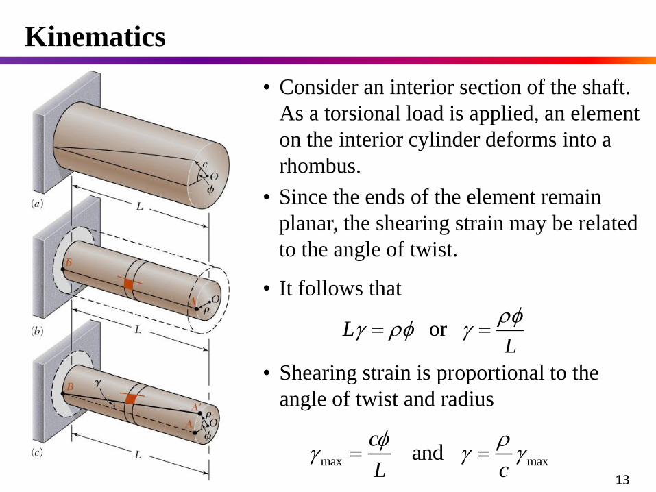
• Consider an interior section of the shaft.
As a torsional load is applied, an element
on the interior cylinder deforms into a
rhombus.
• Shearing strain is proportional to the
angle of twist and radius
max max and c
L c
LL
or
• It follows that
• Since the ends of the element remain
planar, the shearing strain may be related
to the angle of twist.
13
Kinematics
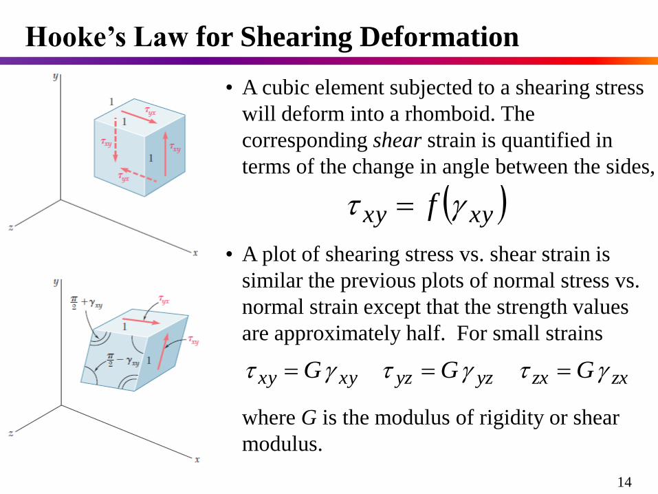
• A cubic element subjected to a shearing stress
will deform into a rhomboid. The
corresponding shear strain is quantified in
terms of the change in angle between the sides,
xyxy f
• A plot of shearing stress vs. shear strain is
similar the previous plots of normal stress vs.
normal strain except that the strength values
are approximately half. For small strains
zxzxyzyzxyxy GGG
where G is the modulus of rigidity or shear
modulus.
Hooke’s Law for Shearing Deformation
14
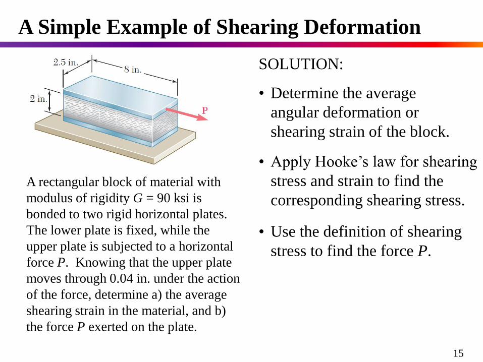
A Simple Example of Shearing Deformation
A rectangular block of material with
modulus of rigidity G = 90 ksi is
bonded to two rigid horizontal plates.
The lower plate is fixed, while the
upper plate is subjected to a horizontal
force P. Knowing that the upper plate
moves through 0.04 in. under the action
of the force, determine a) the average
shearing strain in the material, and b)
the force P exerted on the plate.
SOLUTION:
• Determine the average
angular deformation or
shearing strain of the block.
• Use the definition of shearing
stress to find the force P.
• Apply Hooke’s law for shearing
stress and strain to find the
corresponding shearing stress.
15
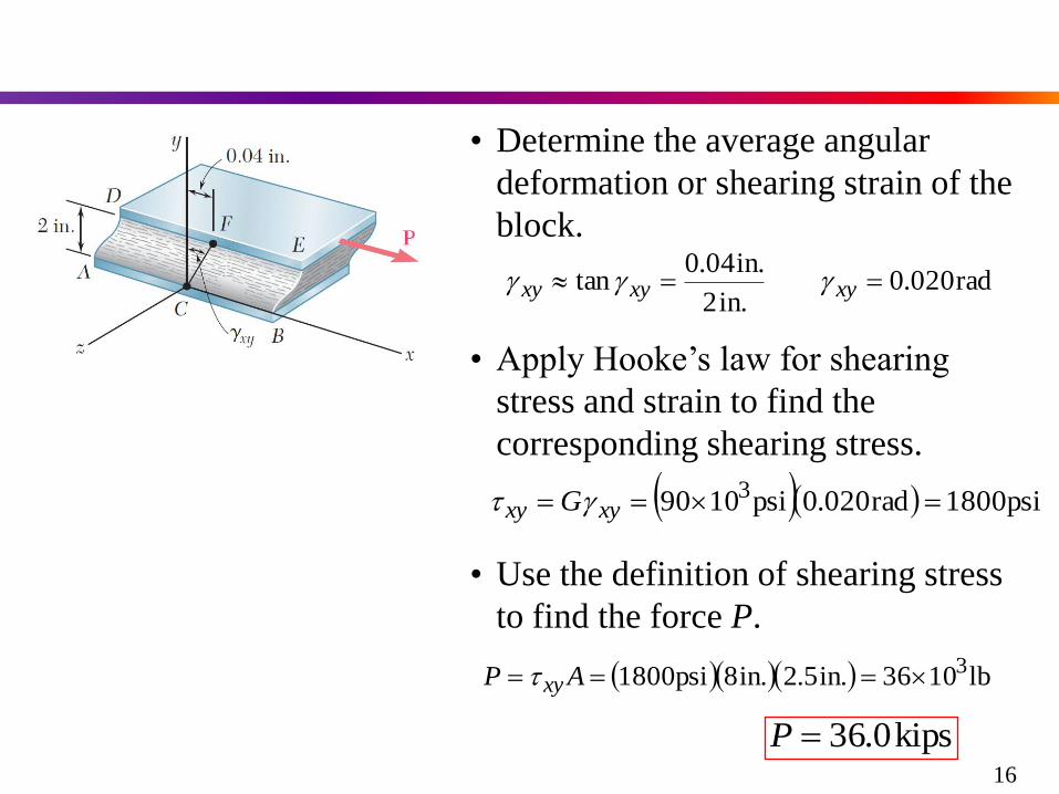
• Determine the average angular
deformation or shearing strain of the
block.
rad020.0in.2
in.04.0tan xyxyxy
• Apply Hooke’s law for shearing
stress and strain to find the
corresponding shearing stress.
psi1800rad020.0psi1090 3 xyxy G
• Use the definition of shearing stress
to find the force P.
lb1036in.5.2in.8psi1800 3 AP xy
kips0.36P16
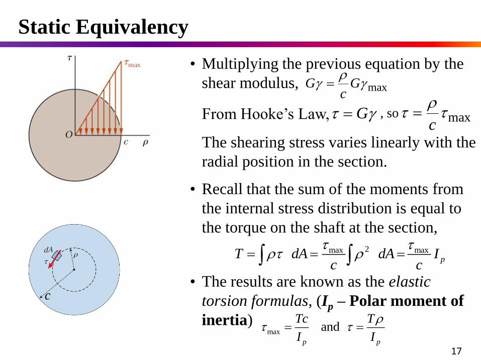
2max maxpT dA dA I
c c
• Recall that the sum of the moments from
the internal stress distribution is equal to
the torque on the shaft at the section,
max and p p
Tc T
I I
• The results are known as the elastic
torsion formulas, (Ip – Polar moment of
inertia)
• Multiplying the previous equation by the
shear modulus, max
Gc
G
max
c
From Hooke’s Law, G , so
The shearing stress varies linearly with the
radial position in the section.
Static Equivalency
17
c
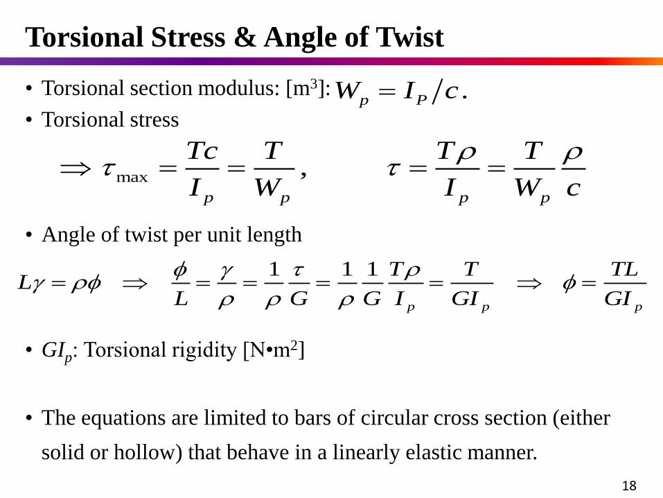
.p PW I c
max ,p p p p
Tc T T T
I W I W c
• Torsional section modulus: [m3]:
1 1 1
p p p
T T TLL
L G G I GI GI
• Angle of twist per unit length
• Torsional stress
• GIp: Torsional rigidity [N•m2]
Torsional Stress & Angle of Twist
18
• The equations are limited to bars of circular cross section (either
solid or hollow) that behave in a linearly elastic manner.
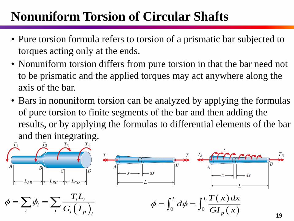
• Pure torsion formula refers to torsion of a prismatic bar subjected to
torques acting only at the ends.
• Nonuniform torsion differs from pure torsion in that the bar need not
to be prismatic and the applied torques may act anywhere along the
axis of the bar.
• Bars in nonuniform torsion can be analyzed by applying the formulas
of pure torsion to finite segments of the bar and then adding the
results, or by applying the formulas to differential elements of the bar
and then integrating.
Nonuniform Torsion of Circular Shafts
0 0
L L
p
T x dxd
GI x
i ii
i i i p i
T L
G I
19
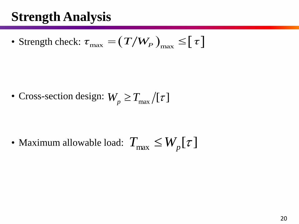
max maxPτ T W τ • Strength check:
• Cross-section design:
• Maximum allowable load:
max [ ]pW T
][max pWT
Strength Analysis
20
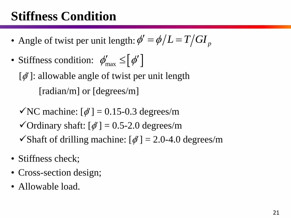
• Stiffness condition:
pL T GI • Angle of twist per unit length:
[]: allowable angle of twist per unit length
[radian/m] or [degrees/m]
NC machine: [] = 0.15-0.3 degrees/m
Ordinary shaft: [] = 0.5-2.0 degrees/m
Shaft of drilling machine: [] = 2.0-4.0 degrees/m
• Stiffness check;
• Cross-section design;
• Allowable load.
max
Stiffness Condition
21
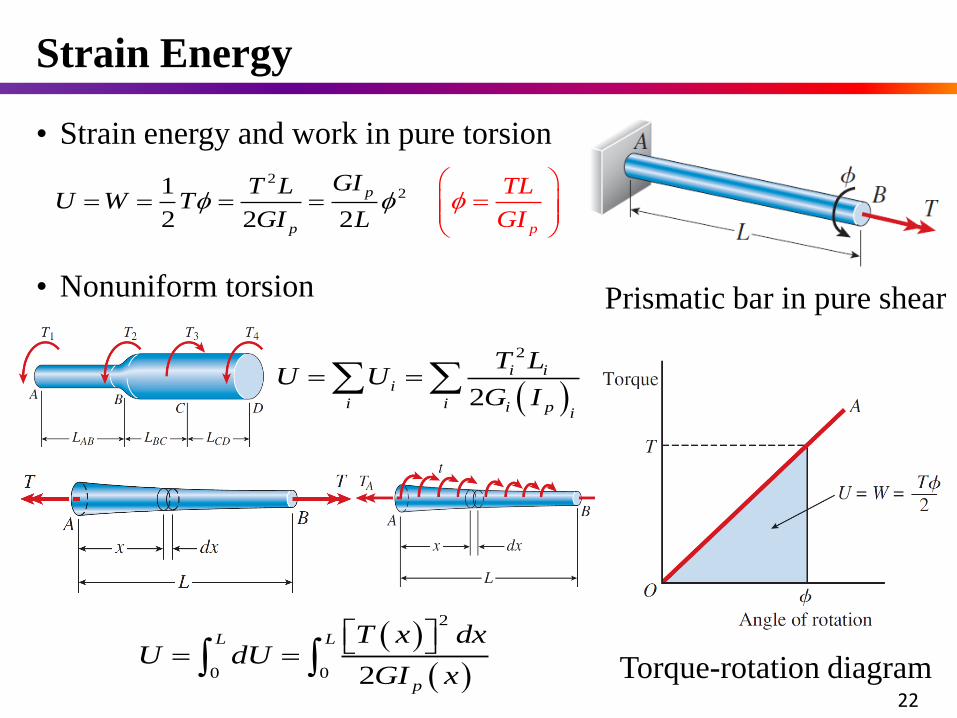
Strain Energy
Torque-rotation diagram
Prismatic bar in pure shear
• Strain energy and work in pure torsion
221
2 2 2
p
p p
TL
G
GIT LU W T
GI L I
2
0 0 2
L L
p
T x dxU dU
GI x
2
2
i ii
i i i p i
T LU U
G I
• Nonuniform torsion
22
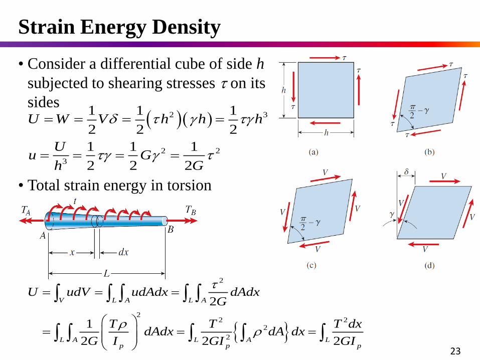
Strain Energy Density
• Consider a differential cube of side h
subjected to shearing stresses on its
sides 2 3
2 2
3
1 1 1
2 2 2
1 1 1
2 2 2
U W V h h h
Uu G
h G
• Total strain energy in torsion
2
22 2
2
2
2
1
2 2 2
V L A L A
L A L A Lp p p
U udV udAdx dAdxG
T T T dxdAdx dA dx
G I GI GI
23
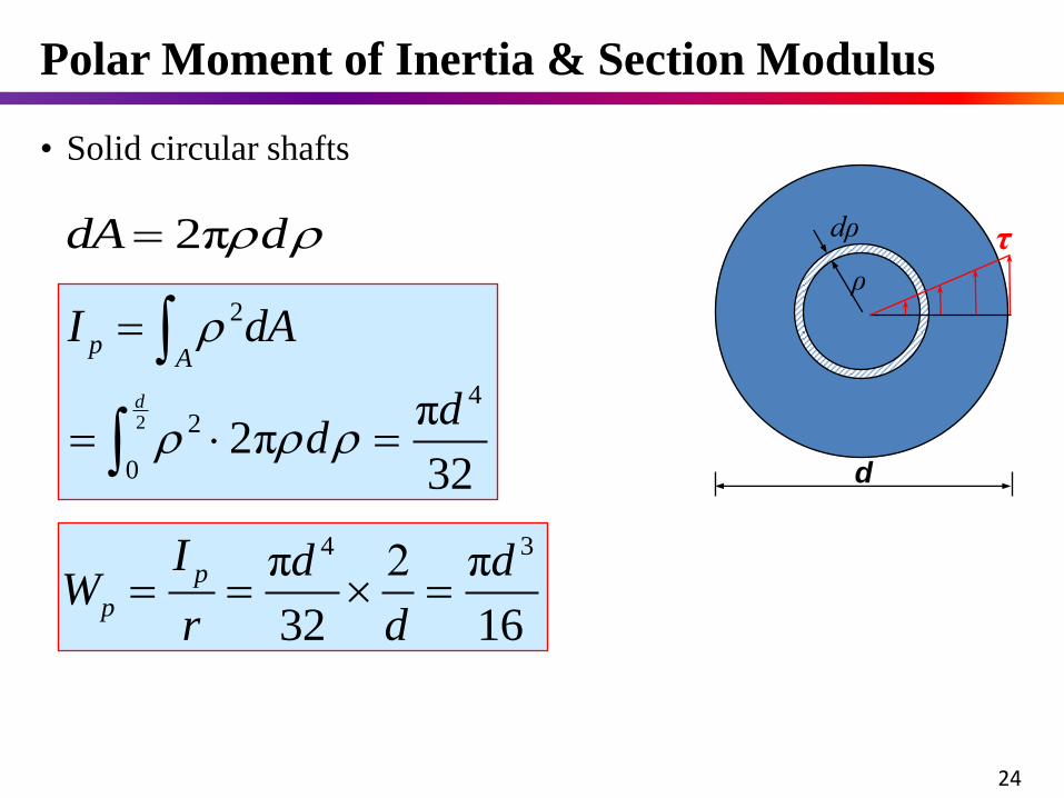
• Solid circular shafts
2
2
42
0
π2π
32
d
pA
I dA
dd
4 3π 2 π
32 16
p
p
I d dW
r d
2πdA d
d
ρ
dρ τ
Polar Moment of Inertia & Section Modulus
24
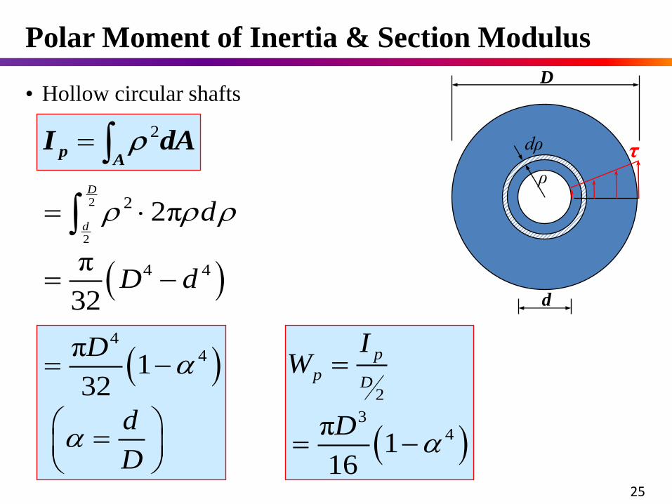
• Hollow circular shafts
dAIA
p 2
2
34π
116
p
pD
IW
D
2
2
2 2πD
dd
4 4π
32D d
4
4π1
32
D
d
D
d
ρ
dρ
D
τ
25
Polar Moment of Inertia & Section Modulus
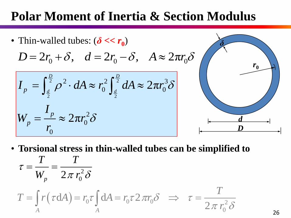
• Thin-walled tubes: (δ << r0)
0 0 02 , 2 , 2πD r d r A r
2 2
2 2
2 2 3
0 0
2
0
0
2π
2π
D D
d dp
p
p
I dA r dA r
IW r
r
d
r0
δ
D
26
0 0 0 2
0
2
0
d d 2 2
2
A A
p
TT r A r A
T T
W
r rr
r
• Torsional stress in thin-walled tubes can be simplified to
Polar Moment of Inertia & Section Modulus
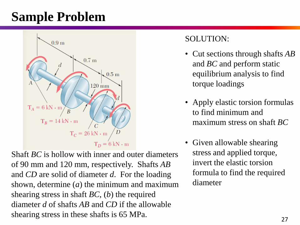
Shaft BC is hollow with inner and outer diameters
of 90 mm and 120 mm, respectively. Shafts AB
and CD are solid of diameter d. For the loading
shown, determine (a) the minimum and maximum
shearing stress in shaft BC, (b) the required
diameter d of shafts AB and CD if the allowable
shearing stress in these shafts is 65 MPa.
SOLUTION:
• Cut sections through shafts AB
and BC and perform static
equilibrium analysis to find
torque loadings
• Given allowable shearing
stress and applied torque,
invert the elastic torsion
formula to find the required
diameter
• Apply elastic torsion formulas
to find minimum and
maximum stress on shaft BC
Sample Problem
27
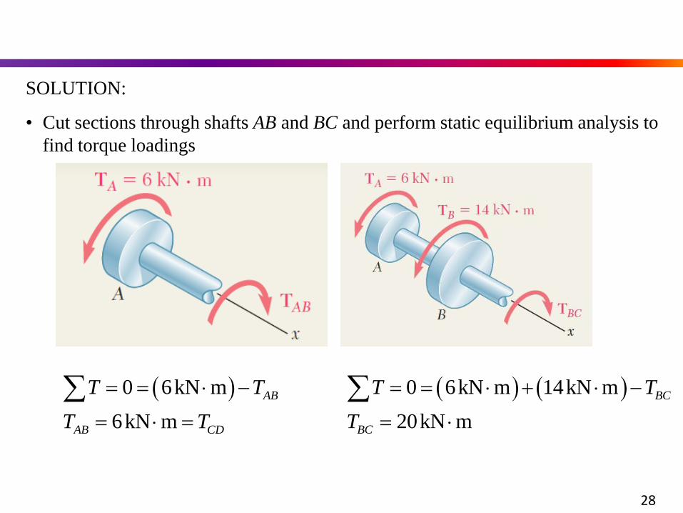
SOLUTION:
• Cut sections through shafts AB and BC and perform static equilibrium analysis to
find torque loadings
0 6kN m
6kN m
AB
AB CD
T T
T T
28
0 6kN m 14kN m
20kN m
BC
BC
T T
T
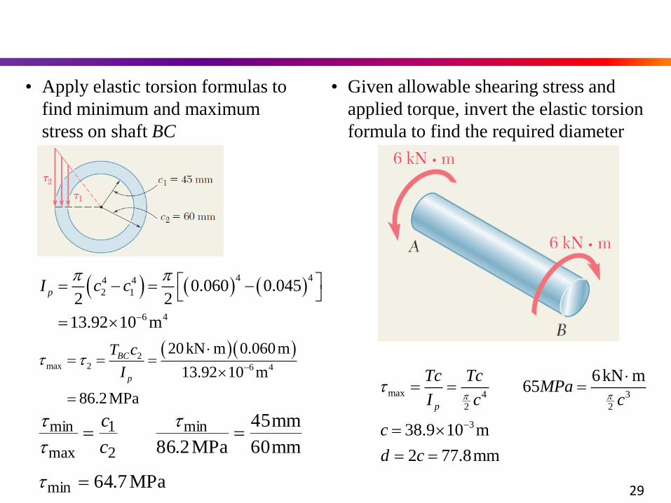
• Apply elastic torsion formulas to
find minimum and maximum
stress on shaft BC
4 44 4
2 1
6 4
0.060 0.0452 2
13.92 10 m
pI c c
2max 2 6 4
20kN m 0.060m
13.92 10 m
86.2MPa
BC
p
T c
I
MPa7.64
mm60
mm45
MPa2.86
min
min
2
1
max
min
c
c
• Given allowable shearing stress and
applied torque, invert the elastic torsion
formula to find the required diameter
max 4 3
2 2
3
6kN m65
38.9 10 m
2 77.8mm
p
Tc TcMPa
I c c
c
d c
29
Sample Problem
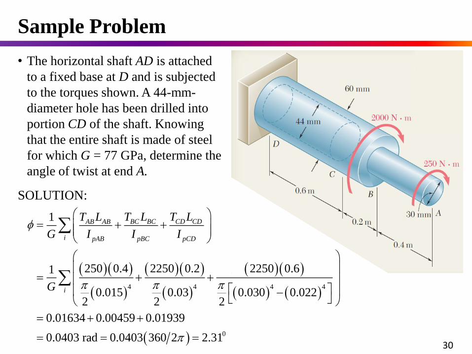
• The horizontal shaft AD is attached
to a fixed base at D and is subjected
to the torques shown. A 44-mm-
diameter hole has been drilled into
portion CD of the shaft. Knowing
that the entire shaft is made of steel
for which G = 77 GPa, determine the
angle of twist at end A.
SOLUTION:
4 4 4 4
0
1
250 0.4 2250 0.2 2250 0.61
0.015 0.03 0.030 0.0222 2 2
0.01634 0.00459 0.01939
0.0403 rad 0.0403 360 2 2.31
BC BC CD CDAB AB
i pAB pBC pCD
i
T L T LT L
G I I I
G
30
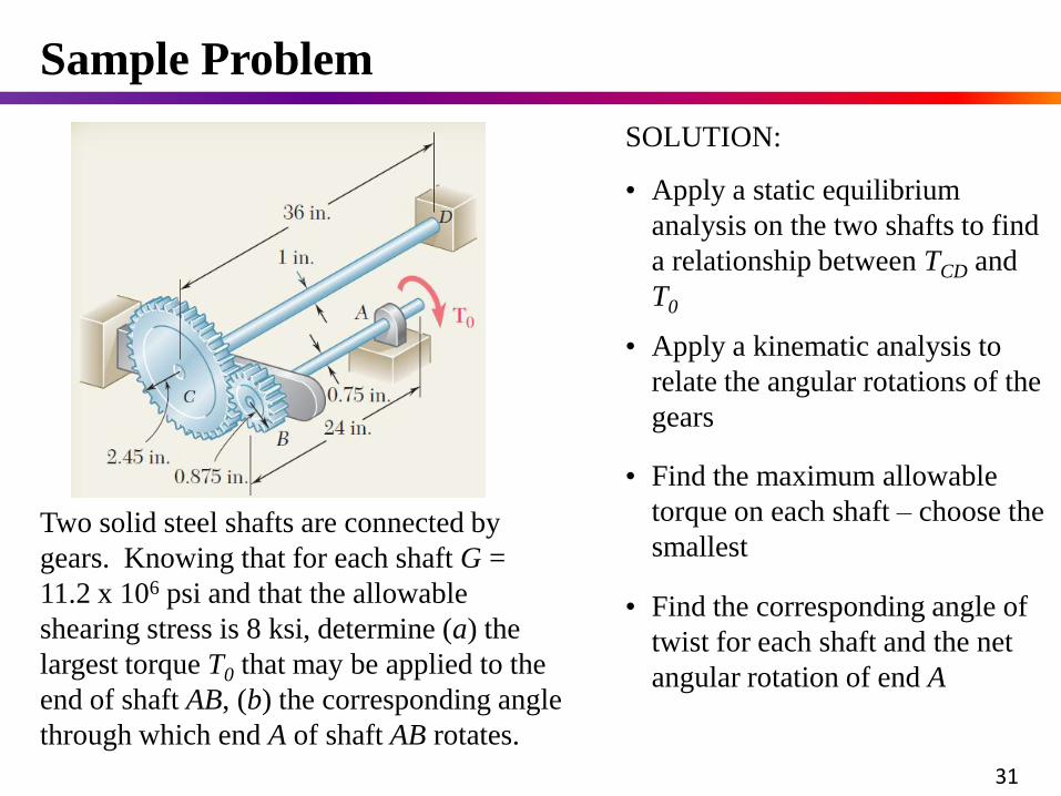
Two solid steel shafts are connected by
gears. Knowing that for each shaft G =
11.2 x 10⁶ psi and that the allowable
shearing stress is 8 ksi, determine (a) the
largest torque T0 that may be applied to the
end of shaft AB, (b) the corresponding angle
through which end A of shaft AB rotates.
SOLUTION:
• Apply a static equilibrium
analysis on the two shafts to find
a relationship between TCD and
T0
• Find the corresponding angle of
twist for each shaft and the net
angular rotation of end A
• Find the maximum allowable
torque on each shaft – choose the
smallest
• Apply a kinematic analysis to
relate the angular rotations of the
gears
Sample Problem
31
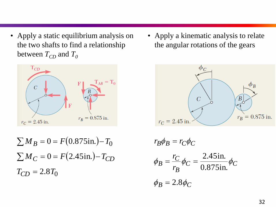
• Apply a static equilibrium analysis on
the two shafts to find a relationship
between TCD and T0
0
0
8.2
in.45.20
in.875.00
TT
TFM
TFM
CD
CDC
B
• Apply a kinematic analysis to relate
the angular rotations of the gears
CB
CCB
CB
CCBB
r
r
rr
8.2
in.875.0
in.45.2
32
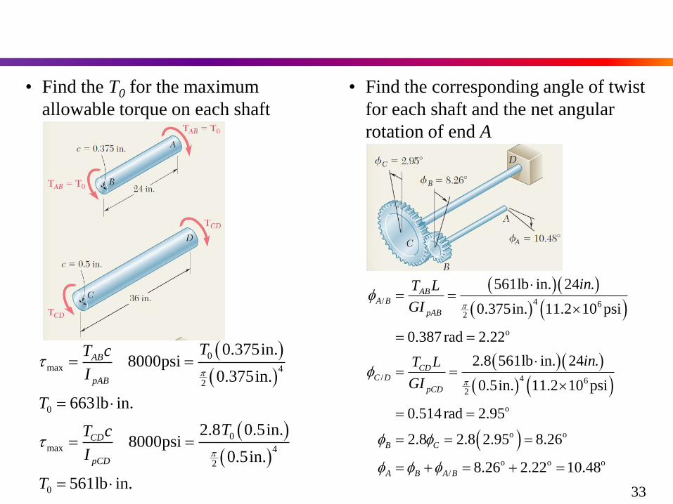
• Find the T0 for the maximum
allowable torque on each shaft
0
max 4
2
0
0
max 4
2
0
0.375in.8000psi
0.375in.
663lb in.
2.8 0.5in.8000psi
0.5in.
561lb in.
AB
pAB
CD
pCD
TT c
I
T
TT c
I
T
• Find the corresponding angle of twist
for each shaft and the net angular
rotation of end A
/ 4 6
2
o
/ 4 6
2
o
o o
o o o
/
561lb in. 24 .
0.375in. 11.2 10 psi
0.387 rad 2.22
2.8 561lb in. 24 .
0.5in. 11.2 10 psi
0.514rad 2.95
2.8 2.8 2.95 8.26
8.26 2.22 10.48
ABA B
pAB
CDC D
pCD
B C
A B A B
inT L
GI
inT L
GI
33
Sample Problem
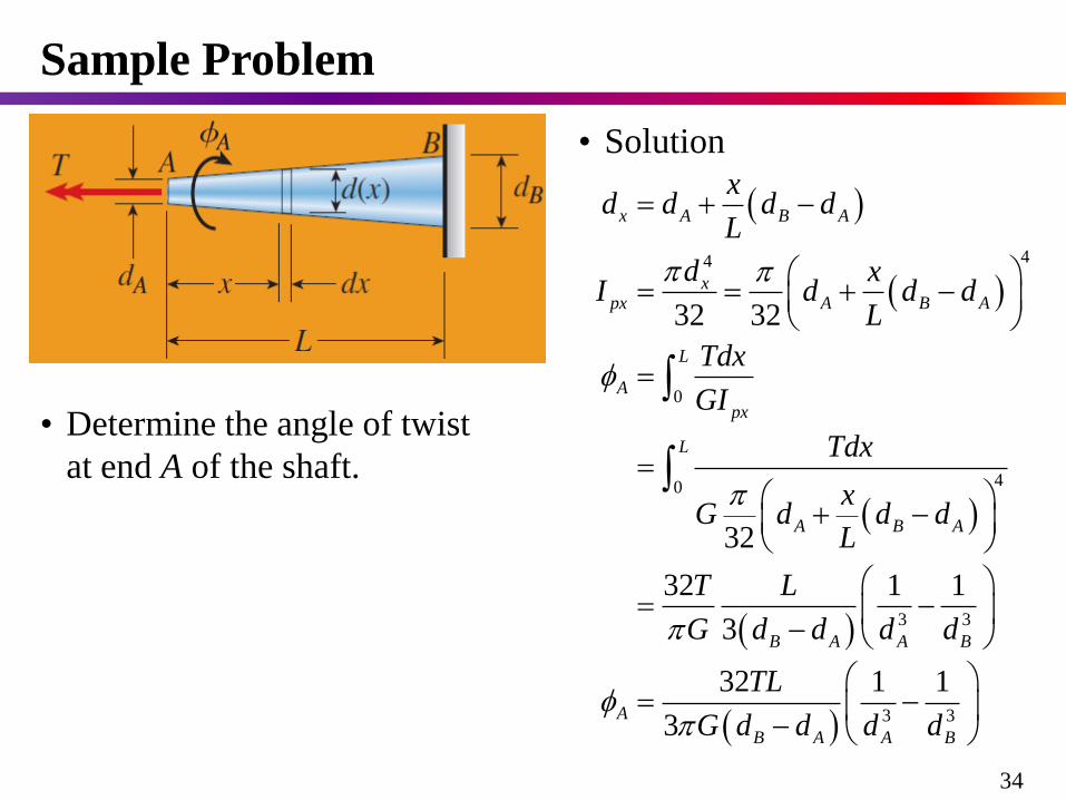
• Determine the angle of twist
at end A of the shaft.
44
0
40
3 3
3 3
32 32
32
32 1 1
3
32 1 1
3
x A B A
xpx A B A
L
A
px
L
A B A
B A A B
A
B A A B
xd d d d
L
d xI d d d
L
Tdx
GI
Tdx
xG d d d
L
T L
G d d d d
TL
G d d d d
• Solution
34
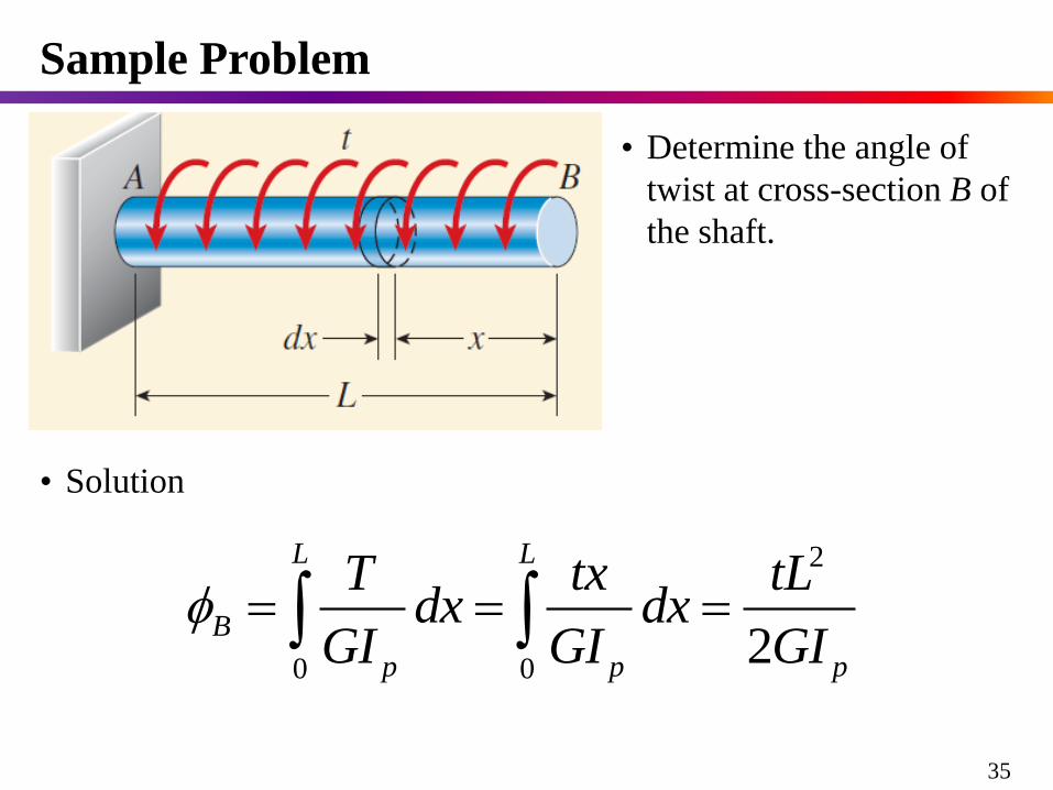
• Determine the angle of
twist at cross-section B of
the shaft.
2
0 02
L L
B
p p p
T tx tLdx dx
GI GI GI
Sample Problem
• Solution
35
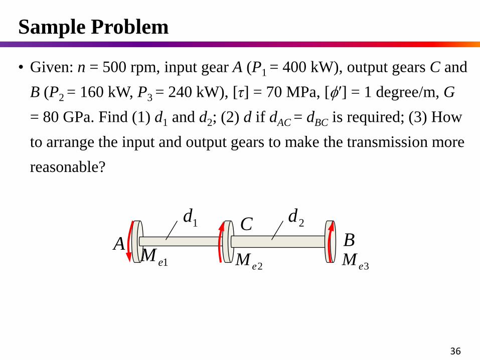
• Given: n = 500 rpm, input gear A (P1 = 400 kW), output gears C and
B (P2 = 160 kW, P3 = 240 kW), [τ] = 70 MPa, [′] = 1 degree/m, G
= 80 GPa. Find (1) d1 and d2; (2) d if dAC = dBC is required; (3) How
to arrange the input and output gears to make the transmission more
reasonable?
1eMA B
C
2eM 3eM
1d 2d
Sample Problem
36
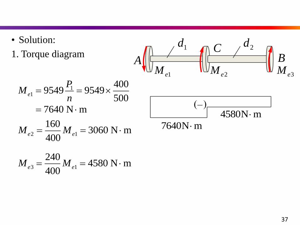
11
4009549 9549
5007640 N m
e
PM
n
2 1
1603060 N m
400e eM M
3 1
2404580 N m
400e eM M
• Solution:
mN7640
mN4580
1eMA B
C
2eM 3eM
1d 2d1. Torque diagram
37
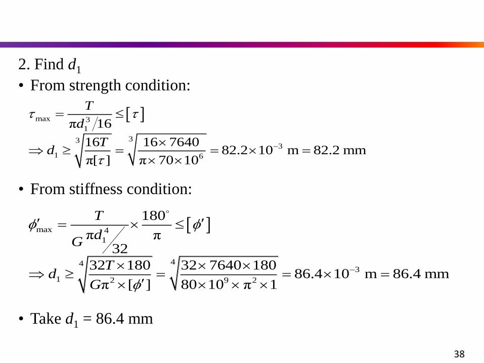
• From stiffness condition:
2. Find d1
• From strength condition:
max 3
1
333
1 6
π 16
16 16 764082.2 10 m 82.2 mm
π[ ] π 70 10
T
d
Td
max 4
1
443
1 2 9 2
180
π π32
32 180 32 7640 18086.4 10 m 86.4 mm
π [ ] 80 10 π 1
T
dG
Td
G
• Take d1 = 86.4 mm
38
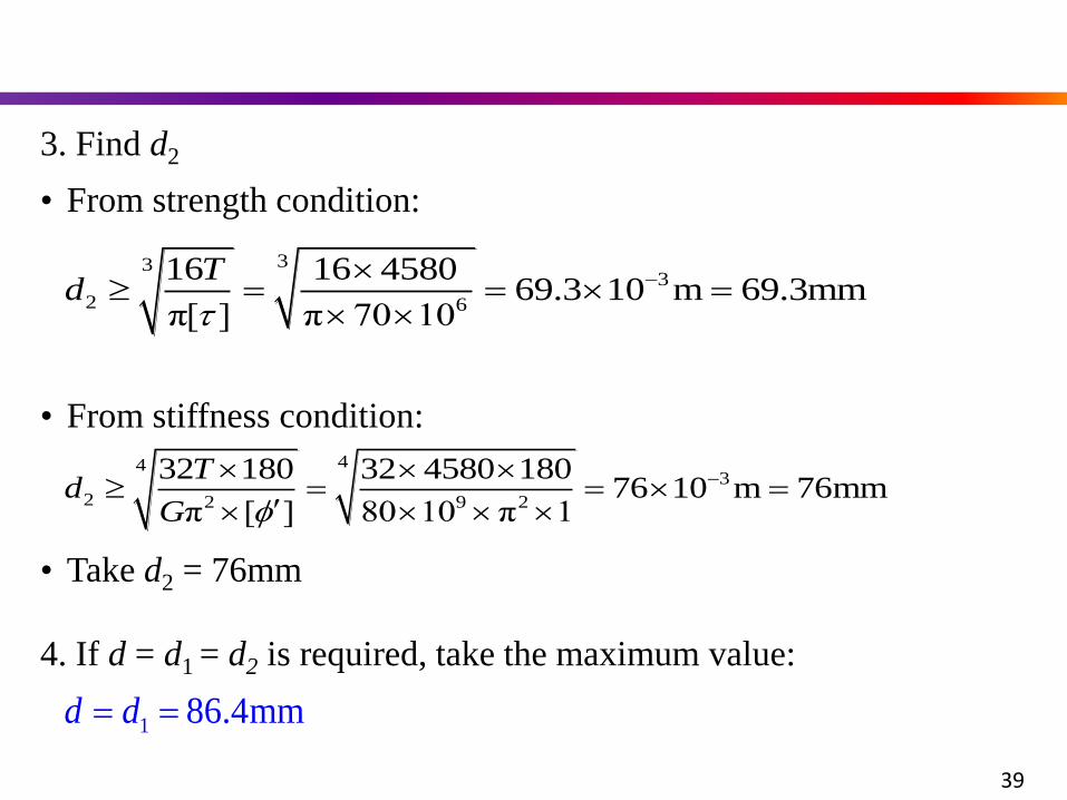
• From stiffness condition:
3. Find d2
• From strength condition:
333
2 6
16 16 458069.3 10 m 69.3mm
π[ ] π 70 10
Td
443
2 2 9 2
32 180 32 4580 18076 10 m 76mm
π [ ] 80 10 π 1
Td
G
4. If d = d1 = d2 is required, take the maximum value:
1 86.4mmd d
• Take d2 = 76mm
39
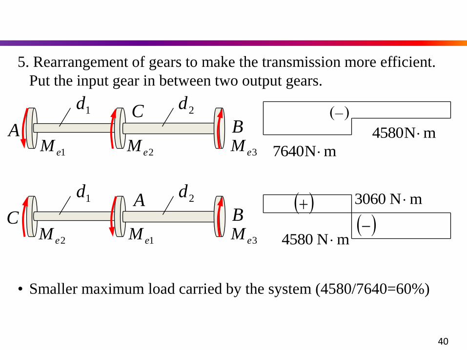
5. Rearrangement of gears to make the transmission more efficient.
Put the input gear in between two output gears.
1eMA B
C
2eM 3eM
1d 2d
mN7640
mN4580
2eMC B
A
1eM 3eM
1d 2d
• Smaller maximum load carried by the system (4580/7640=60%)
3060 N m
4580 N m
40
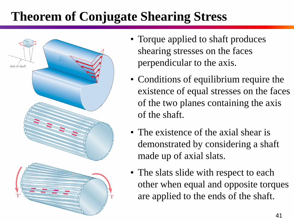
• Torque applied to shaft produces
shearing stresses on the faces
perpendicular to the axis.
• Conditions of equilibrium require the
existence of equal stresses on the faces
of the two planes containing the axis
of the shaft.
• The slats slide with respect to each
other when equal and opposite torques
are applied to the ends of the shaft.
• The existence of the axial shear is
demonstrated by considering a shaft
made up of axial slats.
Theorem of Conjugate Shearing Stress
41
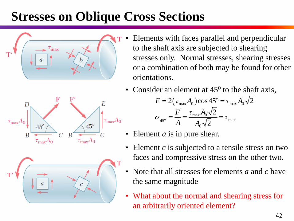
• Note that all stresses for elements a and c have
the same magnitude
• Element c is subjected to a tensile stress on two
faces and compressive stress on the other two.
• Elements with faces parallel and perpendicular
to the shaft axis are subjected to shearing
stresses only. Normal stresses, shearing stresses
or a combination of both may be found for other
orientations.
o
max 0 max 0
max 0max45
0
2 cos 45 2
2
2
F A A
AF
A A
• Consider an element at 450 to the shaft axis,
• Element a is in pure shear.
• What about the normal and shearing stress for
an arbitrarily oriented element?
Stresses on Oblique Cross Sections
42
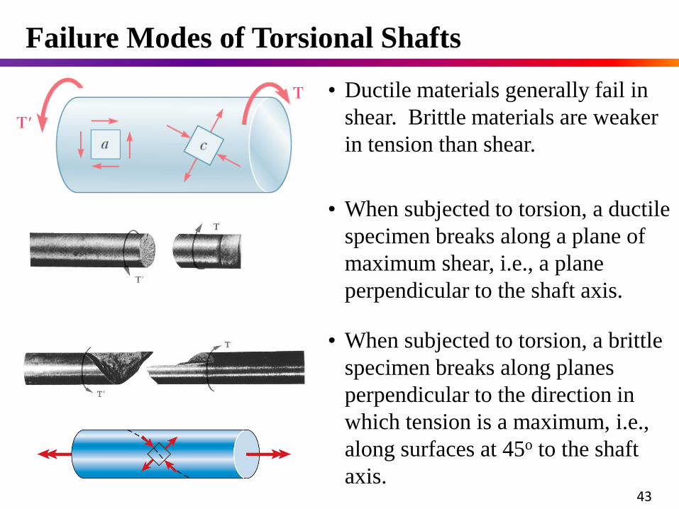
• Ductile materials generally fail in
shear. Brittle materials are weaker
in tension than shear.
• When subjected to torsion, a ductile
specimen breaks along a plane of
maximum shear, i.e., a plane
perpendicular to the shaft axis.
• When subjected to torsion, a brittle
specimen breaks along planes
perpendicular to the direction in
which tension is a maximum, i.e.,
along surfaces at 45o to the shaft
axis.
Failure Modes of Torsional Shafts
43
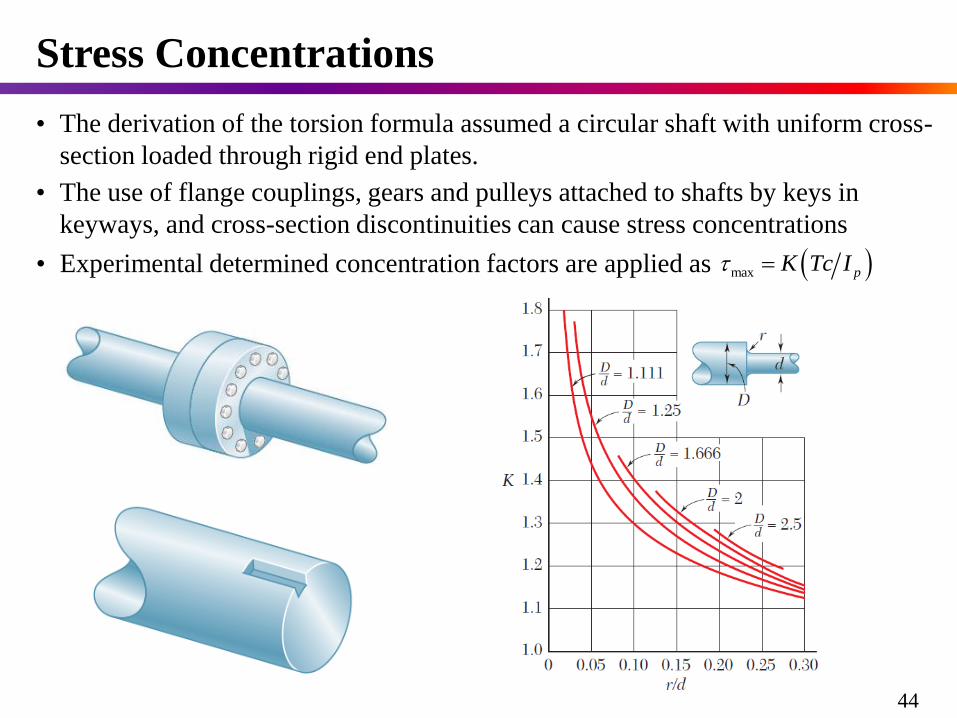
• The derivation of the torsion formula assumed a circular shaft with uniform cross-
section loaded through rigid end plates.
max pK Tc I • Experimental determined concentration factors are applied as
• The use of flange couplings, gears and pulleys attached to shafts by keys in
keyways, and cross-section discontinuities can cause stress concentrations
Stress Concentrations
44
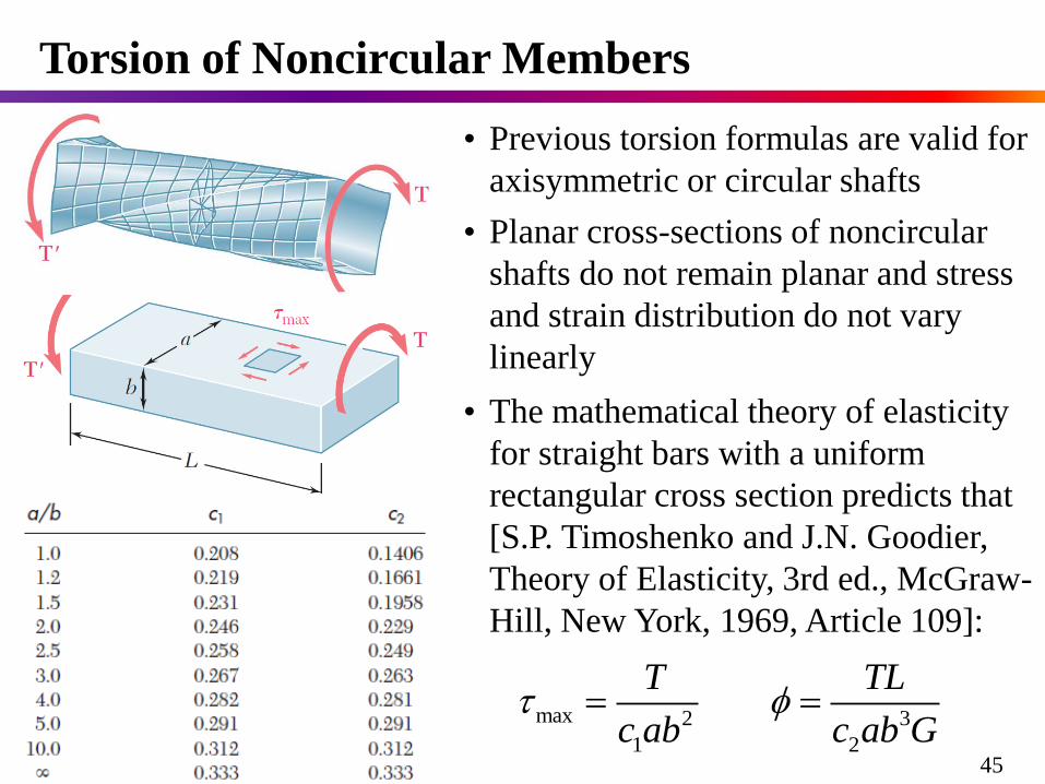
Torsion of Noncircular Members
max 2 3
1 2
T TL
c ab c ab G
• The mathematical theory of elasticity
for straight bars with a uniform
rectangular cross section predicts that
[S.P. Timoshenko and J.N. Goodier,
Theory of Elasticity, 3rd ed., McGraw-
Hill, New York, 1969, Article 109]:
• Previous torsion formulas are valid for
axisymmetric or circular shafts
• Planar cross-sections of noncircular
shafts do not remain planar and stress
and strain distribution do not vary
linearly
45
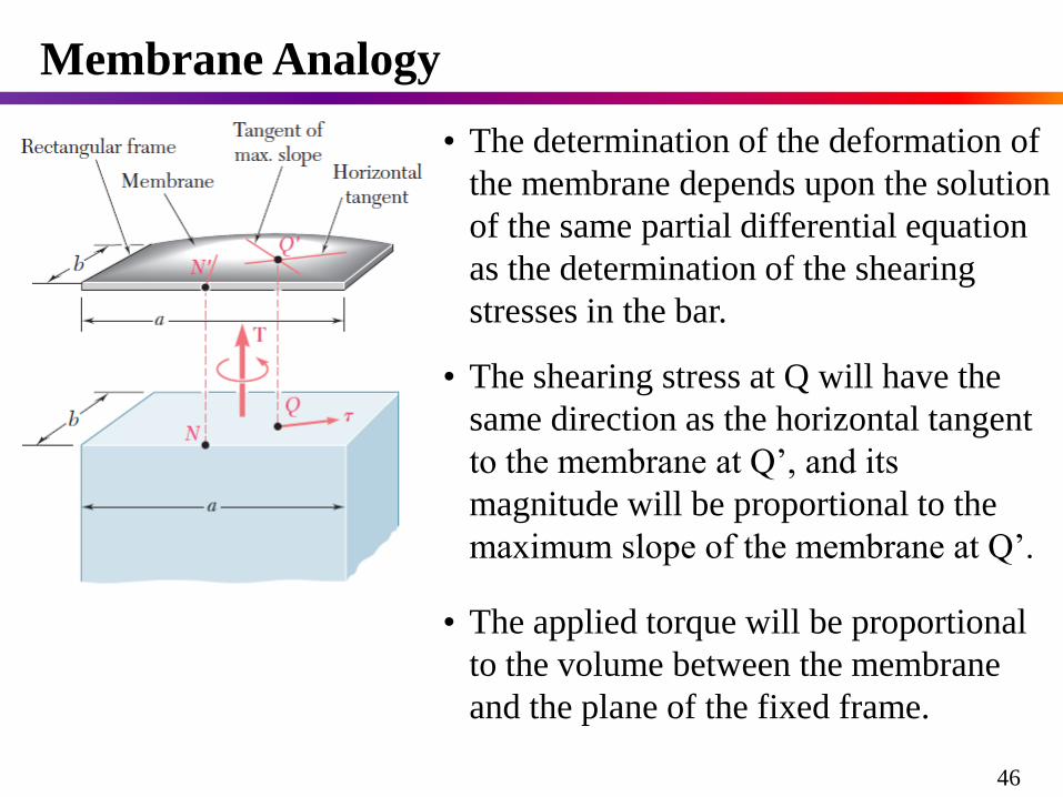
• The determination of the deformation of
the membrane depends upon the solution
of the same partial differential equation
as the determination of the shearing
stresses in the bar.
Membrane Analogy
46
• The shearing stress at Q will have the
same direction as the horizontal tangent
to the membrane at Q’, and its
magnitude will be proportional to the
maximum slope of the membrane at Q’.
• The applied torque will be proportional
to the volume between the membrane
and the plane of the fixed frame.
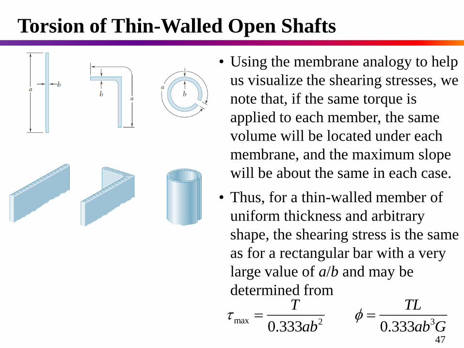
• Using the membrane analogy to help
us visualize the shearing stresses, we
note that, if the same torque is
applied to each member, the same
volume will be located under each
membrane, and the maximum slope
will be about the same in each case.
max 2 30.333 0.333
T TL
ab ab G
Torsion of Thin-Walled Open Shafts
47
• Thus, for a thin-walled member of
uniform thickness and arbitrary
shape, the shearing stress is the same
as for a rectangular bar with a very
large value of a/b and may be
determined from
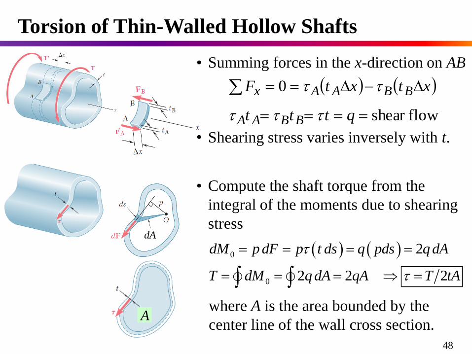
Torsion of Thin-Walled Hollow Shafts
• Summing forces in the x-direction on AB
flowshear
0
qttt
xtxtF
BBAA
BBAAx
0
0
2
2 2 2
dM p dF p t ds q pds q dA
T dM q dA qA T tA
• Compute the shaft torque from the
integral of the moments due to shearing
stress
48
• Shearing stress varies inversely with t.
where A is the area bounded by the
center line of the wall cross section.
dA
A
49
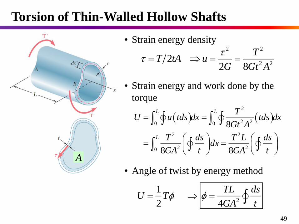
Torsion of Thin-Walled Hollow Shafts
• Strain energy density2 2
2 22
2 8
TT tA u
G Gt A
A
• Angle of twist by energy method
• Strain energy and work done by the
torque
2
2 20 0
2 2
2 20
8
8 8
L L
L
TU u tds dx tds dx
Gt A
T ds T L dsdx
GA t GA t
2
1
2 4
TL dsU T
GA t
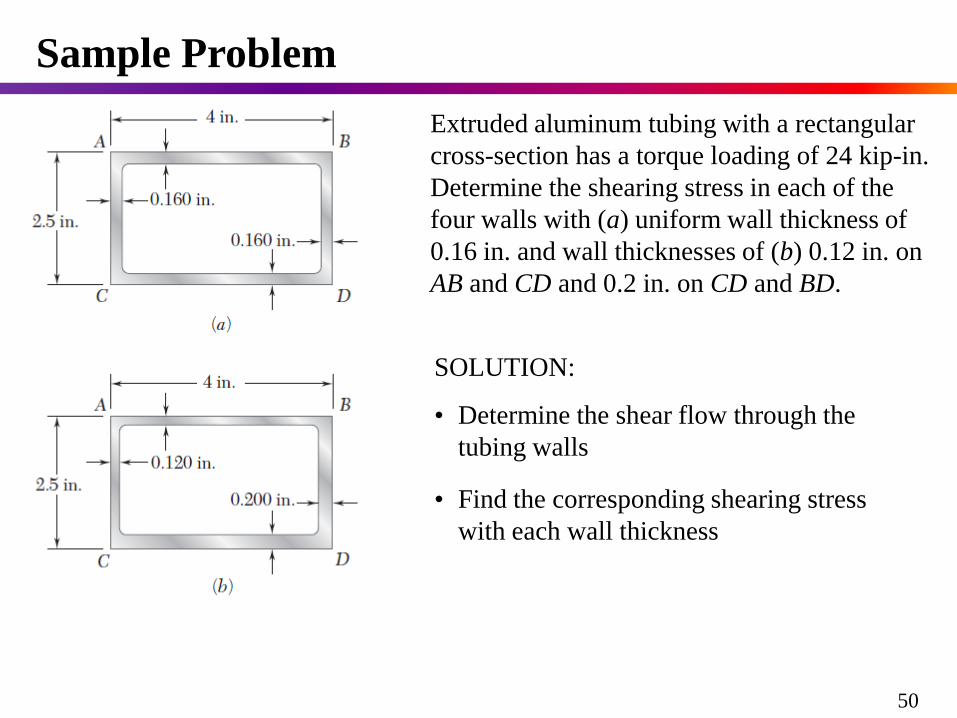
Extruded aluminum tubing with a rectangular
cross-section has a torque loading of 24 kip-in.
Determine the shearing stress in each of the
four walls with (a) uniform wall thickness of
0.16 in. and wall thicknesses of (b) 0.12 in. on
AB and CD and 0.2 in. on CD and BD.
SOLUTION:
• Determine the shear flow through the
tubing walls
• Find the corresponding shearing stress
with each wall thickness
Sample Problem
50
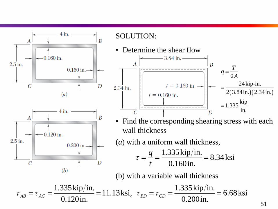
SOLUTION:
• Determine the shear flow
2
24kip-in.
2 3.84in. 2.34in.
kip1.335
in.
Tq
A
• Find the corresponding shearing stress with each
wall thickness
(a) with a uniform wall thickness,
1.335kip in.8.34ksi
0.160in.
q
t
(b) with a variable wall thickness
1.335kip in. 1.335kip in.11.13ksi, 6.68ksi
0.120in. 0.200in.AB AC BD CD
51

• Introduction to Torsion(扭转简介)
• Examples of Torsion Shafts(扭转轴示例)
• Sign Convention of Torque(扭矩符号规则)
• Torque Diagram(扭矩图)
• Power & Torque(功率与扭矩)
• Internal Torque & Stress - Static Indeterminacy(内力扭矩和应力-超静定概念的引入)
• General Relations Involved in Deformable Solids(分析可变形固体的几大基本关系)
• Kinematics(几何关系)
• Hooke’s Law for Shearing Deformation(剪切变形物理关系)
• Static Equivalency(静力等效关系)
• Torsional Stress & Angle of Twist(圆轴扭转的应力与扭转角)
Contents
52

• Nonuniform Torsion of Circular Shafts(圆轴的非均匀扭转)
• Strength & Stiffness Analysis(强度和刚度条件)
• Strain Energy and its Density(扭转应变能与应变能密度)
• Polar Moments of Inertia & Section Modulus(圆截面的极惯性矩与扭转截面系数)
• Theorem of Conjugate Shearing Stress(切应力互等定理)
• Stresses on Oblique Cross Sections(扭转轴斜截面上的应力)
• Failure Modes of Torsional Shafts(扭转轴的失效模式)
• Stress Concentrations(扭转轴的应力集中)
• Torsion of Noncircular Members(非圆截面杆的扭转)
• Membrane Analogy(薄膜比拟)
• Torsion of Thin-walled Open Shafts(薄壁开口截面杆的扭转)
• Torsion of Thin-walled Hollow Shafts(薄壁空心截面杆的扭转)
Contents
53