TR ECU P KONTROL ÜNİTESİ KURULUM KILAVUZU GÖKSU YAPI ... · TR. ECU P. KONTROL ÜNİTESİ....
12
TR
TR ECU P KONTROL ÜNİTESİ KURULUM KILAVUZU GÖKSU YAPI ... · TR. ECU P. KONTROL ÜNİTESİ. KURULUM KILAVUZU. GÖKSU YAPI TEKNOLOJİLERİ A.Ş Genel Müdürlük / Head Office:
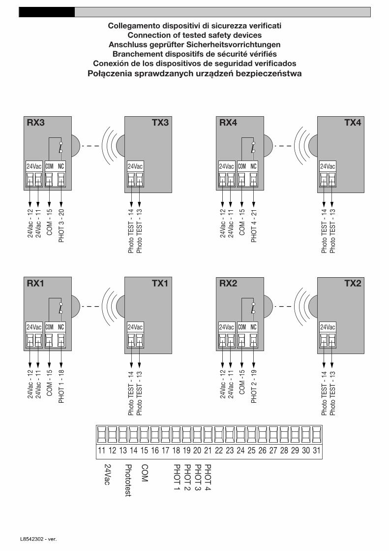
Collegamento dispositivi di sicurezza verificatiConnection of tested safety devices
Anschluss geprüfter SicherheitsvorrichtungenBranchement dispositifs de sécurité vérifiés
Conexión de los dispositivos de seguridad verificadosPołączenia sprawdzanych urządzeń bezpieczeństwa
nihalcavdar
Text Box
Fotosel emniyet sistemleri test bağlantısı
Teknik3
Text Box
KURULUM KILAVUZU
Teknik3
Text Box
TÜRKÇE
nihalcavdar
Text Box
L8542302 - ver.01 - 4
4
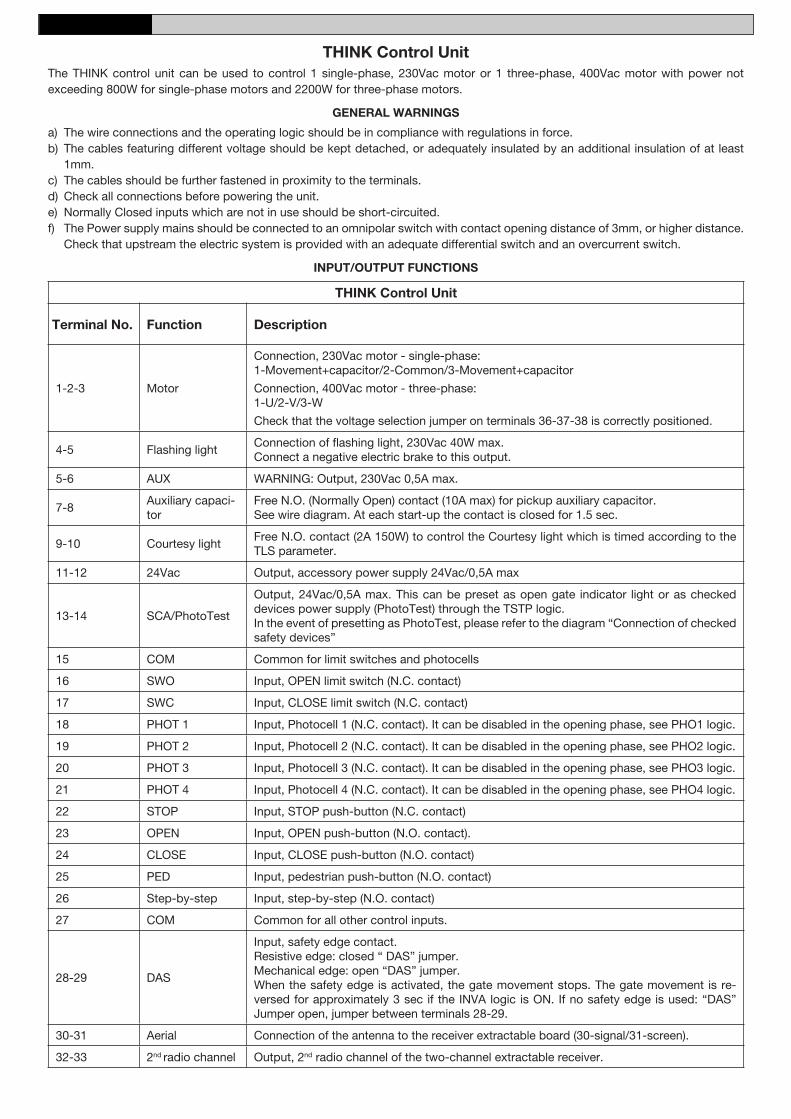
THINK Control UnitThe THINK control unit can be used to control 1 single-phase, 230Vac motor or 1 three-phase, 400Vac motor with power not exceeding 800W for single-phase motors and 2200W for three-phase motors.
GENERAL WARNINGS
a) The wire connections and the operating logic should be in compliance with regulations in force. b) The cables featuring different voltage should be kept detached, or adequately insulated by an additional insulation of at least
1mm.c) The cables should be further fastened in proximity to the terminals.d) Check all connections before powering the unit.e) Normally Closed inputs which are not in use should be short-circuited.f) The Power supply mains should be connected to an omnipolar switch with contact opening distance of 3mm, or higher distance.
Check that upstream the electric system is provided with an adequate differential switch and an overcurrent switch.
INPUT/OUTPUT FUNCTIONS
THINK Control Unit
Terminal No. Function Description
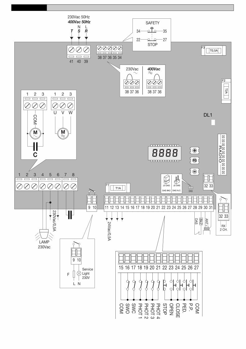
1-2-3 Motor
Connection, 230Vac motor - single-phase:1-Movement+capacitor/2-Common/3-Movement+capacitor
Connection, 400Vac motor - three-phase: 1-U/2-V/3-W
Check that the voltage selection jumper on terminals 36-37-38 is correctly positioned.
4-5 Flashing lightConnection of flashing light, 230Vac 40W max. Connect a negative electric brake to this output.
5-6 AUX WARNING: Output, 230Vac 0,5A max.
7-8Auxiliary capaci-tor
Free N.O. (Normally Open) contact (10A max) for pickup auxiliary capacitor.See wire diagram. At each start-up the contact is closed for 1.5 sec.
9-10 Courtesy lightFree N.O. contact (2A 150W) to control the Courtesy light which is timed according to the TLS parameter.
11-12 24Vac Output, accessory power supply 24Vac/0,5A max
13-14 SCA/PhotoTest
Output, 24Vac/0,5A max. This can be preset as open gate indicator light or as checked devices power supply (PhotoTest) through the TSTP logic.In the event of presetting as PhotoTest, please refer to the diagram “Connection of checked safety devices”
15 COM Common for limit switches and photocells
16 SWO Input, OPEN limit switch (N.C. contact)
17 SWC Input, CLOSE limit switch (N.C. contact)
18 PHOT 1 Input, Photocell 1 (N.C. contact). It can be disabled in the opening phase, see PHO1 logic.
19 PHOT 2 Input, Photocell 2 (N.C. contact). It can be disabled in the opening phase, see PHO2 logic.
20 PHOT 3 Input, Photocell 3 (N.C. contact). It can be disabled in the opening phase, see PHO3 logic.
21 PHOT 4 Input, Photocell 4 (N.C. contact). It can be disabled in the opening phase, see PHO4 logic.
Input, safety edge contact. Resistive edge: closed “ DAS” jumper.Mechanical edge: open “DAS” jumper.When the safety edge is activated, the gate movement stops. The gate movement is re-versed for approximately 3 sec if the INVA logic is ON. If no safety edge is used: “DAS” Jumper open, jumper between terminals 28-29.
30-31 Aerial Connection of the antenna to the receiver extractable board (30-signal/31-screen).
32-33 2nd radio channel Output, 2nd radio channel of the two-channel extractable receiver.
Kenar emniyet sistemi kontağı. Dirençli kenar emniyet sistemi: kapalı "DAS" jumper'i. Mekanik kenar emniyet sistemi: açık "DAS" jumper'i. Kenar emniyet sistemi aktive edildiği zaman, kapı hareketi durur. Eğer INVA lojiği ON ise, kapı hareketi yaklaşık 3 sn. için tersine döner. Hiç güvenlik kenar emniyet sistemi kullanılmamışsa: 28-29 terminalleri arasındaki "DAS" jumper'i açık.
nihalcavdar
Text Box
Radyo alıcı kartı anten bağlantısı (30-sinyal / 31-ekran)
nihalcavdar
Text Box
Radyo alıcı kartı ikinci kanal çıkışı
nihalcavdar
Text Box
UYARI: Çıkış, 230Vac 0,5A maks.
nihalcavdar
Text Box
Çıkış, aksesuar güç kaynağı 24Vac / 0,5A maks.
nihalcavdar
Text Box
Foto Test
nihalcavdar
Text Box
Bağlantı, 230Vac motor, tek faz: 1- Hareket + kondansatör / 2- Ortak uç / 3- Hareket + kondansatör Bağlantı, 400Vac motor, üç faz: 1- U /2- V /3- W 36-37-38 numaralı terminallerdeki gerilim seçme jumper'ının yerleşimini kontrol edin.
nihalcavdar
Text Box
Flaşör lambanın bağlantısı, 230Vac, 40W maks. Bu çıkışa bir negatif elektrikli fren bağlayın.
nihalcavdar
Text Box
Yardımcı kondansatör için serbest N.O. (Normalde Açık) kontak (10A maks.). Bağlantı şemasına bakınız. Her başlangıçta 1,5 sn. için kapalı kalır.
nihalcavdar
Text Box
Zaman ayarı TLS paramaetresine göre yapılmış olan, açılışta otomatik olarak yanan lambanın kontrolü için serbest N.O. kontak (2A, 150W)
nihalcavdar
Text Box
Çıkış, 24Vac / 0,5A maks. Bu, TSTP lojiği üzerinden, kapı açık lambası veya fotosel test bağlantısı olarak ayarlanabilir. Foto Test olarak ayarlanması halinde "fotosel emniyet sistemleri test bağlantısı" diagramına bakınız.
Teknik3
Text Box
KURULUM KILAVUZU
Teknik3
Text Box
TÜRKÇE
nihalcavdar
Text Box
L8542302 - ver.01 - 5
nihalcavdar
Text Box
Yardımcı kontak
nihalcavdar
Text Box
Ortak
nihalcavdar
Text Box
Açma anahtarı
nihalcavdar
Text Box
Kapama anahtarı
nihalcavdar
Text Box
Fotosel1
nihalcavdar
Text Box
Fotosel2
nihalcavdar
Text Box
Fotosel3
nihalcavdar
Text Box
Fotosel4
nihalcavdar
Text Box
Durdurma
nihalcavdar
Text Box
Açma
nihalcavdar
Text Box
Kapama
nihalcavdar
Text Box
Yaya girişi
nihalcavdar
Text Box
Ortak
nihalcavdar
Text Box
Kenar emniyet sistemi
nihalcavdar
Text Box
ECU P Kontrol Ünitesi ECU Kontrol Ünitesi, 230 Vac, gücü 800 W'tan fazla olmayan bir tek fazlı motoru veya 400 Vac, gücü 2200 W'tan fazla olmayan bir üç fazlı motoru kontrol etmek için kullanılabilir. GENEL UYARILAR a) Kablo bağlantıları ve işlem mantığı talimatlara kesinlikle uygun olmalıdır. b) Farklı voltajlar taşıyan kablolar birbirinden ayrı tutulmalı veya en az 1 mm 'lik ek izolasyonla iyice izole edilmelidir. c) Kablolar terminallere oldukça yakın bağlanmalıdır. d) Üniteye güç vermeden önce bütün bağlantıları kontrol edin. e) Kullanılmayan Normalde Kapalı girişleri kısa devre edin. f ) Güç kaynağı bağlantıları, kontak açılma mesafesi 3 mm. veya daha fazla olan bir tek kutuplu anahtara bağlanmalıdır. Elektrik sisteminde uygun bir kaçak akım rölesi ve aşırı akım koruyucu sigortası olup olmadığını kontrol edin.
7
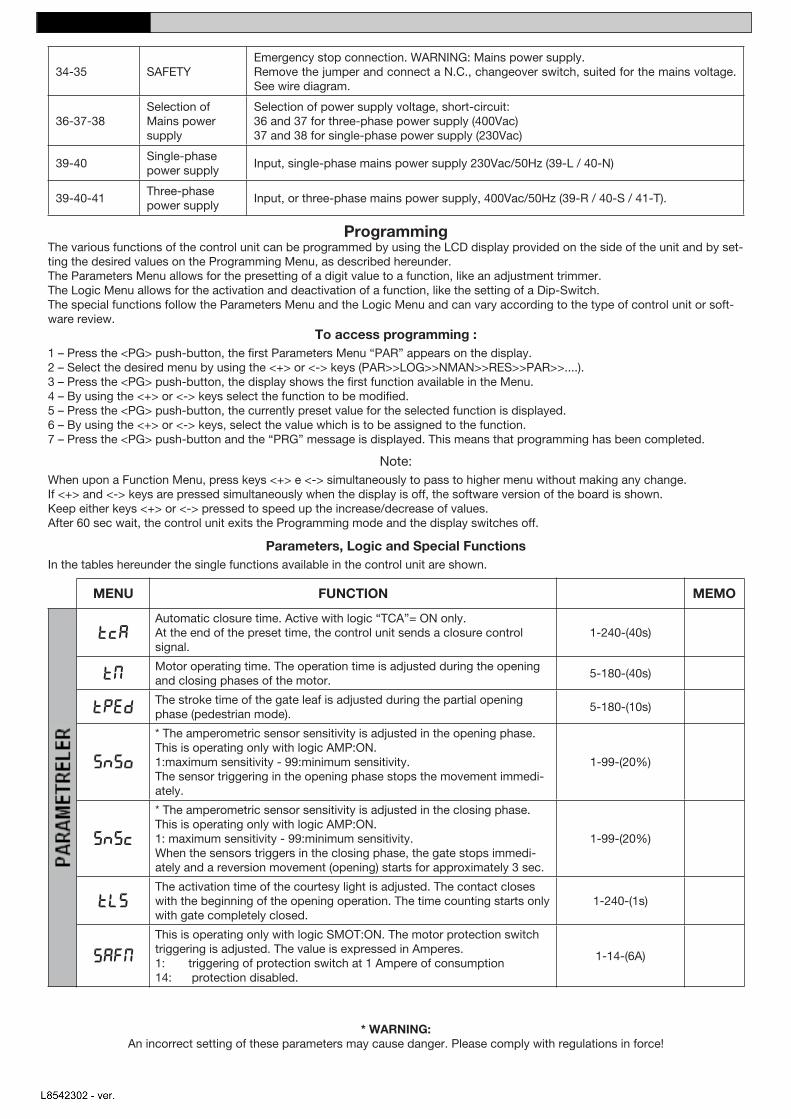
34-35 SAFETYEmergency stop connection. WARNING: Mains power supply.Remove the jumper and connect a N.C., changeover switch, suited for the mains voltage. See wire diagram.
36-37-38Selection of Mains power supply
Selection of power supply voltage, short-circuit:36 and 37 for three-phase power supply (400Vac)37 and 38 for single-phase power supply (230Vac)
39-40Single-phase power supply
Input, single-phase mains power supply 230Vac/50Hz (39-L / 40-N)
39-40-41Three-phase power supply
Input, or three-phase mains power supply, 400Vac/50Hz (39-R / 40-S / 41-T).
Programming The various functions of the control unit can be programmed by using the LCD display provided on the side of the unit and by set-ting the desired values on the Programming Menu, as described hereunder.The Parameters Menu allows for the presetting of a digit value to a function, like an adjustment trimmer. The Logic Menu allows for the activation and deactivation of a function, like the setting of a Dip-Switch.The special functions follow the Parameters Menu and the Logic Menu and can vary according to the type of control unit or soft-ware review.
To access programming :1 – Press the <PG> push-button, the first Parameters Menu “PAR” appears on the display. 2 – Select the desired menu by using the <+> or <-> keys (PAR>>LOG>>NMAN>>RES>>PAR>>....).3 – Press the <PG> push-button, the display shows the first function available in the Menu.4 – By using the <+> or <-> keys select the function to be modified.5 – Press the <PG> push-button, the currently preset value for the selected function is displayed.6 – By using the <+> or <-> keys, select the value which is to be assigned to the function.7 – Press the <PG> push-button and the “PRG” message is displayed. This means that programming has been completed.
Note: When upon a Function Menu, press keys <+> e <-> simultaneously to pass to higher menu without making any change. If <+> and <-> keys are pressed simultaneously when the display is off, the software version of the board is shown.Keep either keys <+> or <-> pressed to speed up the increase/decrease of values.After 60 sec wait, the control unit exits the Programming mode and the display switches off.
Parameters, Logic and Special Functions In the tables hereunder the single functions available in the control unit are shown.
MENU FUNCTION MEMO
PA
RA
ME
TE
RS
TCAAutomatic closure time. Active with logic “TCA”= ON only.At the end of the preset time, the control unit sends a closure control signal.
1-240-(40s)
TMMotor operating time. The operation time is adjusted during the opening and closing phases of the motor.
5-180-(40s)
TpedThe stroke time of the gate leaf is adjusted during the partial opening phase (pedestrian mode).
5-180-(10s)
SnSo
* The amperometric sensor sensitivity is adjusted in the opening phase. This is operating only with logic AMP:ON. 1:maximum sensitivity - 99:minimum sensitivity.The sensor triggering in the opening phase stops the movement immedi-ately.
1-99-(20%)
SnSC
* The amperometric sensor sensitivity is adjusted in the closing phase. This is operating only with logic AMP:ON. 1: maximum sensitivity - 99:minimum sensitivity.When the sensors triggers in the closing phase, the gate stops immedi-ately and a reversion movement (opening) starts for approximately 3 sec.
1-99-(20%)
TLSThe activation time of the courtesy light is adjusted. The contact closes with the beginning of the opening operation. The time counting starts only with gate completely closed.
1-240-(1s)
SaFM
This is operating only with logic SMOT:ON. The motor protection switch triggering is adjusted. The value is expressed in Amperes. 1: triggering of protection switch at 1 Ampere of consumption 14: protection disabled.
1-14-(6A)
* WARNING: An incorrect setting of these parameters may cause danger. Please comply with regulations in force!
nihalcavdar
Text Box
Programlama Kontrol ünitesinin farklı fonksiyonları, ünitenin bir yanında bulunan LCD monitor vasıtasıyla, Programlama Menüsünden istenen değeri burada anlatıldığı gibi ayarlayarak programlanabilir. Parametre Menüsü bir fonksiyona ait rakamsal değerin ayarlanması gibi işlemler gerçekleştirir. Lojik menüsü bir fonksiyonun aktif yada pasif hale getirilmesine olanak sağlar. Parametre menüsünü ve Lojik menüsünü özel fonksiyonlar takip eder ve kontrol ünitesinin tipine yada yazılımın yenilenmesine göre değişebilir. Programlamaya ulaşmak için: 1 - <PG> butonuna basın. İlk Parametre Menüsü “PAR” ekranda belirir. 2 - <+> ve <-> düğmelerini kullanarak istenen menüyü seçin. (PAR>>LOG>>NMAN>>RES>>PAR>> …). 3 - <PG> butonuna basın. Ekran menüdeki ilk fonksiyonu gösterir. 4 - <+> ve <-> düğmelerini kullanarak değiştirilecek fonksiyonu seçin. 5 - <PG> butonuna basın. Seçilen fonksiyonun önceden ayarlanmış değeri görüntülenir. 6 - <+> ve <-> düğmelerini kullanarak fonksiyona atanacak değeri seçin. 7 - <PG> butonuna basın. “PRG” mesajı görüntülenir. Bu programlamanın bittiği anlamına gelir. Not: Bir fonksiyon menüsündeyken, herhangi bir değişiklik yapmadan bir üst menüye geçmek için, eşzamanlı olarak <+> ve <-> tuşlarına basın. Eğer ekran kapalıyken <+> ve <-> tuşlarına aynı anda basılırsa kartın yazılım versiyonu görüntülenir. Değerlerin artma / azalma hızını yükseltmek için <+> veya <-> tuşlarını basılı tutun. 60 saniye bekledikten sonra, kontrol ünitesi Programlama modundan çıkar ve ekran kapanır. Parametreler, Lojik ve Özel Fonksiyonlar Aşağıda, kontrol ünitesinde mevcut olan tekli fonksiyonlar gösterilmiştir.
nihalcavdar
Text Box
FONKSİYON
nihalcavdar
Text Box
MENÜ
nihalcavdar
Text Box
VARSAYILAN DEĞERLER
nihalcavdar
Text Box
HAFIZA
nihalcavdar
Text Box
Otomatik kapanma zamanı. Sadece lojik “TCA”=ON durumunda aktif olur. Ayarlanan sürenin sonunda kontrol ünitesi, kapanma kontrol sinyali gönderir.
nihalcavdar
Text Box
Motor çalışma zamanı. Çalışma zamanı, motorun açılma ve kapanma süreleri esas alınarak ayarlanır.
* Akım algılama metodu ile engel tanıma hassasiyeti, kapı açılma yönünde iken ayarlanır. Bu sadece lojik AMP:ON iken çalışır. 1: maksimum hassasiyet, 99: minimum hassasiyet Kapı açılma yönünde iken özelliğin devreye girmesi, hareketi anında durdurur.
nihalcavdar
Text Box
* Akım algılama metodu ile engel tanıma hassasiyeti, kapı açılma yönünde iken ayarlanır. Bu sadece lojik AMP:ON iken çalışır. 1: maksimum hassasiyet, 99: minimum hassasiyet Kapı açılma yönünde iken özelliğin devreye girmesi halinde, kapı anında durur ve yaklaşık 3 sn. süreyle açılma yönünde hareket eder.
nihalcavdar
Text Box
Kapı açıldığında yanan otomatik lambanın süresi ayarlanır. Kontak, açılma işleminin başında kapanır. Zaman sayacı yalnızca kapı tamamen kapandığında başlar.
nihalcavdar
Text Box
Bu sadece lojik SMOT:ON iken çalışır. Motor koruma switch tetiklemesi ayarlanmıştır. Birimi Amper'dir. 1: Motor koruma switch'inin tetiklemesi. (Eşik değeri 1 Amper ) 14: Motor koruma devre dışı.
nihalcavdar
Text Box
*UYARI: Bu parametrelerin yanlış ayarlanması tehlikeye yol açabilir. Lütfen talimatlara kesinlikle uyunuz!
nihalcavdar
Text Box
Emniyet
nihalcavdar
Text Box
Ana güç kaynağı seçimi
nihalcavdar
Text Box
Tek fazlı güç kaynağı
nihalcavdar
Text Box
Üç fazlı güç kaynağı
nihalcavdar
Text Box
Giriş, tek fazlı ana güç kaynağı 230 Vac/50Hz (39-L / 40-N)
nihalcavdar
Text Box
Giriş veya üç fazlı ana güç kaynağı 400 Vac/50Hz (39-R / 40-S / 41-T)
nihalcavdar
Text Box
Güç kaynağı geriliminin seçimi, kısadevre: Üç fazlı güç kaynağı için 36 ve 37 (400Vac) Tek fazlı güç kaynağı için 37 ve 38 (230Vac)
nihalcavdar
Text Box
Acil durdurma bağlantısı. UYARI: Ana güç kaynağı. Jumper'ı kaldırın ve ana gerilime uygun N.C. kontaklı bir şalter bağlayın. Bağlantı şemasına bakınız.
nihalcavdar
Stamp
Teknik3
Text Box
KURULUM KILAVUZU
Teknik3
Text Box
TÜRKÇE
nihalcavdar
Text Box
L8542302 - ver.01 - 6
6
MENU FUNCTION MEMOL
OG
IC
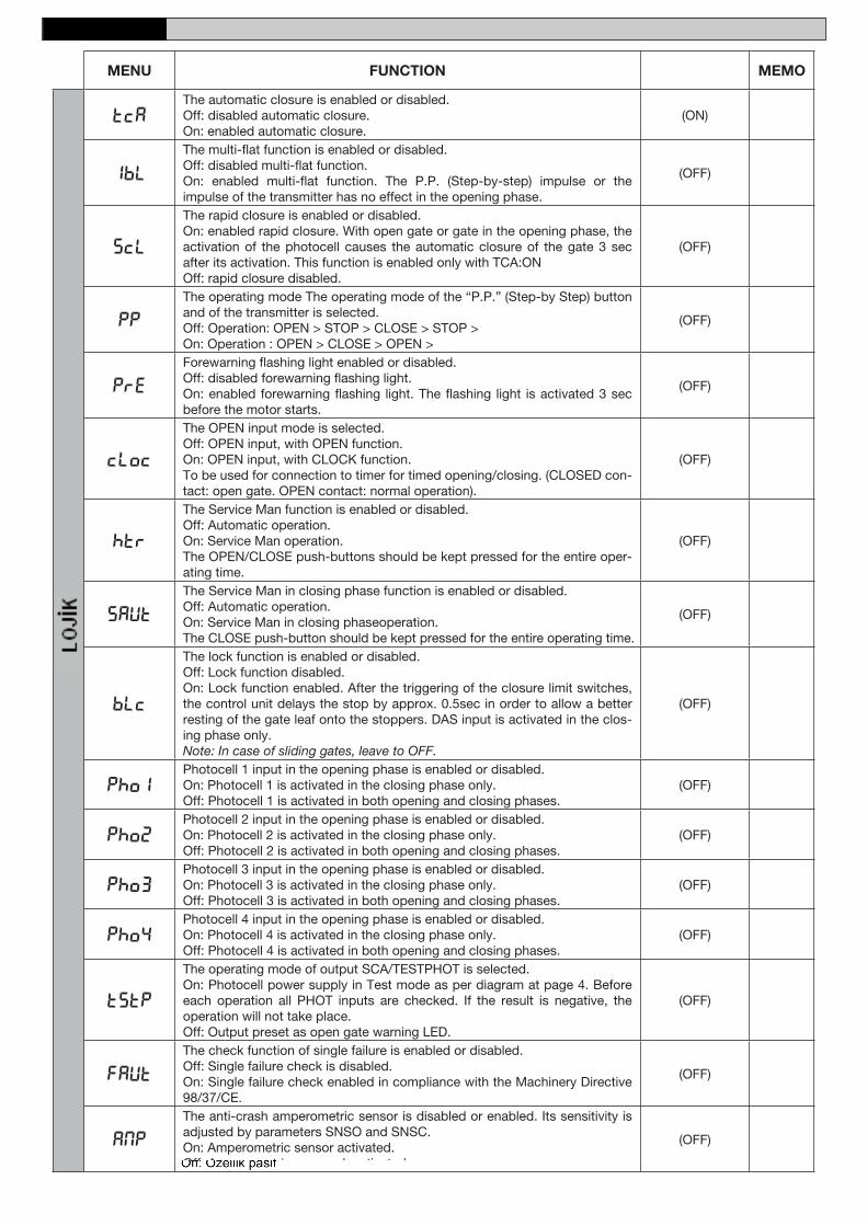
TCAThe automatic closure is enabled or disabled.Off: disabled automatic closure.On: enabled automatic closure.
(ON)
IbL
The multi-flat function is enabled or disabled. Off: disabled multi-flat function. On: enabled multi-flat function. The P.P. (Step-by-step) impulse or the impulse of the transmitter has no effect in the opening phase.
(OFF)
SCL
The rapid closure is enabled or disabled.On: enabled rapid closure. With open gate or gate in the opening phase, the activation of the photocell causes the automatic closure of the gate 3 sec after its activation. This function is enabled only with TCA:ON Off: rapid closure disabled.
(OFF)
PP
The operating mode The operating mode of the “P.P.” (Step-by Step) button and of the transmitter is selected.Off: Operation: OPEN > STOP > CLOSE > STOP >On: Operation : OPEN > CLOSE > OPEN >
(OFF)
PRE
Forewarning flashing light enabled or disabled.Off: disabled forewarning flashing light.On: enabled forewarning flashing light. The flashing light is activated 3 sec before the motor starts.
(OFF)
CLOC
The OPEN input mode is selected.Off: OPEN input, with OPEN function.On: OPEN input, with CLOCK function.To be used for connection to timer for timed opening/closing. (CLOSED con-tact: open gate. OPEN contact: normal operation).
(OFF)
htr
The Service Man function is enabled or disabled.Off: Automatic operation.On: Service Man operation. The OPEN/CLOSE push-buttons should be kept pressed for the entire oper-ating time.
(OFF)
saut
The Service Man in closing phase function is enabled or disabled.Off: Automatic operation.On: Service Man in closing phaseoperation. The CLOSE push-button should be kept pressed for the entire operating time.
(OFF)
BLC
The lock function is enabled or disabled.Off: Lock function disabled.On: Lock function enabled. After the triggering of the closure limit switches, the control unit delays the stop by approx. 0.5sec in order to allow a better resting of the gate leaf onto the stoppers. DAS input is activated in the clos-ing phase only.Note: In case of sliding gates, leave to OFF.
(OFF)
Pho1Photocell 1 input in the opening phase is enabled or disabled.On: Photocell 1 is activated in the closing phase only.Off: Photocell 1 is activated in both opening and closing phases.
(OFF)
Pho2Photocell 2 input in the opening phase is enabled or disabled.On: Photocell 2 is activated in the closing phase only.Off: Photocell 2 is activated in both opening and closing phases.
(OFF)
Pho3Photocell 3 input in the opening phase is enabled or disabled.On: Photocell 3 is activated in the closing phase only.Off: Photocell 3 is activated in both opening and closing phases.
(OFF)
Pho4Photocell 4 input in the opening phase is enabled or disabled.On: Photocell 4 is activated in the closing phase only.Off: Photocell 4 is activated in both opening and closing phases.
(OFF)
TSTP
The operating mode of output SCA/TESTPHOT is selected.On: Photocell power supply in Test mode as per diagram at page 4. Before each operation all PHOT inputs are checked. If the result is negative, the operation will not take place.Off: Output preset as open gate warning LED.
(OFF)
Faut
The check function of single failure is enabled or disabled.Off: Single failure check is disabled.On: Single failure check enabled in compliance with the Machinery Directive 98/37/CE.
(OFF)
AMP
The anti-crash amperometric sensor is disabled or enabled. Its sensitivity is adjusted by parameters SNSO and SNSC.On: Amperometric sensor activated.Off: Amperometric sensor deactivated.
(OFF)
nihalcavdar
Text Box
MENÜ
nihalcavdar
Text Box
FONKSİYON
nihalcavdar
Text Box
VARSAYILAN DEĞERLER
nihalcavdar
Text Box
HAFIZA
nihalcavdar
Text Box
Otomatik kapanma aktif veya pasif Off: Otomatik kapanma pasif On: Otomatik kapanma aktif
nihalcavdar
Text Box
Açılma yönünde buton veya kumanda komutlarını devre dışı bırakma fonksiyonu Off: Fonksiyon pasif On: Fonksiyon aktif. P.P. (adım adım) tahriği veya transmiterin tahriği açılma fazında etkisizdir.
nihalcavdar
Text Box
Hızlı kapanma aktif veya pasif On: Hızlı kapanma aktif. Kapı açıkken veya açılma durumundayken, fotoselin tetiklenmesi, 3 sn. sonra kapının otomatik olarak kapanmasına sebep olur. Bu fonksiyon yalnızca TCA:ON iken çalışır. Off Hızlı kapanma pasif
nihalcavdar
Text Box
P.P. (adım adım) butonunun ve uzaktan kumandanın çalışma modu seçilir. Off: Çalışma: AÇ > DUR > KAPA > DUR ON: Çalışma: AÇ > KAPA > AÇ
nihalcavdar
Text Box
Ön uyarı flaşör lambası aktif veya pasif Off: Erken uyarı flaşör lambası pasif. On: Erken uyarı flaşör lambası aktif. Flaşör lamba, motor çalışmadan 3 sn. önce aktif olur.
nihalcavdar
Text Box
AÇMA komutu modu seçilir. Off: AÇMa girişi, AÇMa fonksiyonunda On: AÇMA girişi, SAAT girişi fonksiyonunda Süreli açma/kapama için zamanlayıcıya bağlantı yapmak için kullanılır. (KAPALI kontak: açık kapı. AÇIK kontak: normal işlem).
nihalcavdar
Text Box
Kapının açma ve kapama işlemleri butona basarak gerçekleştirilir. Off: Otomatik işlem. On: Servis elemanı işlemi. Tüm işlem zamanı için, AÇMA/KAPAMA butonları basılı tutulabilir.
nihalcavdar
Text Box
Kapanma fazında servis elemanı fonksiyonu aktif veya pasif Off: Otomatik işlem. On: Kapanma fazında servis elemanı işlemi. Tüm işlem zamanı için, KAPA butonu basılı tutulabilir.
nihalcavdar
Text Box
Kilit fonksiyonu aktif veya pasif Off: Kilit fonksiyonu pasif On: Kilit fonksiyonu aktif. Kapanma limit switch'lerinin tetiklenmesinden sonra, kapı alt lastiğinin yere daha iyi yerleşmesi için, kontrol ünitesi durma işlemini yaklaşık 0,5 sn. geciktirir. Kenar Emniyet Sİstemi girişleri sadece kapanma fazında aktive olur. Not: Kayar kapılarda OFF'ta bırakın.
nihalcavdar
Text Box
Açılma fazındaki fotosel1 girişi aktif veya pasif On: Fotosel1 sadece kapanma fazında aktif olur. Off: Fotosel1 hem açılma hem kapanma fazında aktif olur.
nihalcavdar
Text Box
Açılma fazındaki fotosel1 girişi aktif veya pasif On: Fotosel2 sadece kapanma fazında aktif olur. Off: Fotosel2 hem açılma hem kapanma fazında aktif olur.
nihalcavdar
Text Box
Açılma fazındaki fotosel1 girişi aktif veya pasif On: Fotosel3 sadece kapanma fazında aktif olur. Off: Fotosel3 hem açılma hem kapanma fazında aktif olur.
nihalcavdar
Text Box
Açılma fazındaki fotosel1 girişi aktif veya pasif On: Fotosel4 sadece kapanma fazında aktif olur. Off: Fotosel4 hem açılma hem kapanma fazında aktif olur.
nihalcavdar
Text Box
tStP… SCA / TESTPHOT çıkışının çalışma modu seçilir On: Sayfa 4'teki diagramda görüldüğü gibi, Test modunda fotosel güç kaynağı. Her işlemden önce bütün PHOT girişleri kontrol edilir. Eğer sonuç negatifse işlem başlamaz. Off: çıkış açık kapı uyarı LEDi olarak setlenir.
nihalcavdar
Text Box
Hata kontrol fonksiyonu aktif veya pasif. Off: Hata kontrol fonksiyonu pasif. On: Hata kontrol fonksiyonu Makine Talimatları 98/37/CE'ye göre aktif.
nihalcavdar
Text Box
Akım algılama metodu ile engel tanıma özelliği aktif veya pasif. Hassasiyeti SNSO ve SNSC parametreleri ile ayarlanır. On: Özellik aktif Off: Özellik pasif
nihalcavdar
Stamp
Teknik3
Text Box
KURULUM KILAVUZU
Teknik3
Text Box
TÜRKÇE
nihalcavdar
Text Box
L8542302 - ver.01 - 7
9
MENU FUNCTION MEMOL
OG
IC
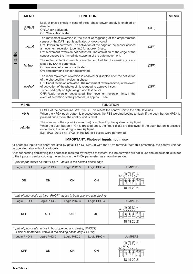
2pha
Lack of phase check in case of three-phase power supply is enabled or disabled.On: Check activated.Off: Check deactivated.
(OFF)
inva
The movement reversion in the event of triggering of the amperometric sensor or the DAS input is activated or deactivared.On: Reversion activated. The activation of the edge or the sensor causes a movement reversion (opening) for approx. 3 sec.Off: Movement reversion not activated. The activation of the edge or the sensor causes the immediate stopping of the gate movement.
(OFF)
Smot
The motor protection switch is enabled or disabled. Its sensitivity is ad-justed by SAFM parameter.On: amperometric sensor activated.Off: amperometric sensor deactivated.
(OFF)
doSp
The rapid movement reversion is enabled or disabled after the activation of the photocell in the closing phase.ON: Rapid reversion activated. The movement reversion time, in the event of activation of the photocell, is reduced to approx. 1 sec.To be used only on light-weight and fast doors.OFF: Rapid reversion deactivated. The movement reversion time, in the event of activation of the photocell, is approx. 3 sec.
(OFF)
MENU FUNCTION
RESRESET of the control unit. WARNING!: This resets the control unit to the default values.When the <PG> push-button is pressed once, the RES wording begins to flash, if the push-button <PG> is pressed once more, the control unit is reset.
NMAN
The number of the cycles (open+close) completed by the system is displayed.When the push-button <PG> is pressed once, the first 4 digits are displayed, if the push-button is pressed once more, the last 4 digits are displayed. E.g. <PG> 0012 >>> <PG> 3456: 123.456 cycles were performed.
IMPORTANT: Photocell inputs not in use
All photocell inputs are short-circuited by default (PHOT1/2/3/4) with the COM terminal. With this presetting, the control unit can be operated also without photocells.
After connecting and setting the photocells required by the type of system, the inputs which are not in use should be short-circuited to the inputs in use by copying the settings in the PHOx parameter, as shown hereunder:
1 pair of photocells on input PHOT1, active in the closing phase only:
1 çift fotosel, hem açma hem kapama durumunda aktif (PHOT1 ve PHOT2) + 1 çift fotosel, sadece kapama durumunda aktif (PHOT3)
nihalcavdar
Text Box
PHOT1 girişinde 1 çift fotosel, hem açma hem kapama durumunda aktif
nihalcavdar
Text Box
PHOT1 girişinde 1 çift fotosel, sadece kapama durumunda aktif
nihalcavdar
Text Box
Üç fazlı güç kaynağı durumunda, faz kontrolünün yokluğu aktif veya pasif. On: Kontrol aktif. Off: Kontrol pasif.
nihalcavdar
Text Box
Akım algılama metodu ile engel tanıma özelliğinin veya DAS girişinin tetiklenmesi durumundaki hareket terslemesi aktif veya pasif. On: Terleme aktif. Köşenin yada sensörün aktivasyonu yaklaşık 3 sn. için hareket terslenmesine (açılma) sebep olur. Off: Hareket terslemesi aktif değil. Köşenin yada sensörün aktivasyonu kapı hareketinin aniden durmasına sebep olur.
nihalcavdar
Text Box
Motor koruma switch'i aktif vaya pasif. Hassasiyeti SAFM parametresi ile ayarlanır. On: Akım algılama metodu ile engel tanıma özelliği aktif Off: Akım algılama metodu ile engel tanıma özelliği pasif
nihalcavdar
Text Box
Kapama durumunda fotoselin aktive olmasından sonraki hızlı hareket terslemesi aktif veya pasif. ON: Hızlı tersleme aktif. Fotoselin aktive olması halindeki hareket tersleme zamanı yaklaşık 1 saniyeye düşürülmüştür. Sadece hafif ve hızlı kapılarda kullanılır. OFF: hızlı tersleme pasif. Fotoselin aktive olması halindeki hareket tersleme zamanı yaklaşık 3 saniyedir.
nihalcavdar
Text Box
UYARI: Kontrol ünitesi ayarlarını Fabrika ayarlarına döndürür. <PG> butonu bir kez basıldığında, ekranda RES kelimesi yanıp sönmeye başlar, <PG> butonuna tekrar basılırsa kontrol ünitesi fabrika ayarlarına döner
nihalcavdar
Text Box
Sistemin tamamladığı çevrimlerin (açma+kapama) sayısı gösterilir. <PG> butonu bir kez basıldığında, ilk 4 hane gösterilir, <PG> butonuna tekrar basılırsa son 4 hane gösterilir. Örn: <PG> 0012>>>> <PG> 3456: 123.456 çevrim gerçekleştirilmiştir.
nihalcavdar
Text Box
ÖNEMLİ: Kullanılmayan fotosel girişleri Bütün fotosel girişleri (PHOT1/2/3/4) varsayılan olarak COM terminali ile kısadevre edilmiştir. Bu önsetlemeyle, kontrol ünitesi fotoselsiz de çalıştırılabilir. Sistem türü tarafından ihtiyaç duyulan fotoseller bağlandıktan ve ayarlandıktan sonra, kullanılmayan girişler aşağıda gösterildiği gibi, PHOx parametresi kullanılarak, kullanılan girişlere kısadevre edilir:
nihalcavdar
Text Box
MENÜ
nihalcavdar
Text Box
FONKSİYON
nihalcavdar
Text Box
VARSAYILAN DEĞERLER
nihalcavdar
Text Box
HAFIZA
nihalcavdar
Stamp
nihalcavdar
Text Box
MENÜ
nihalcavdar
Text Box
FONKSİYON
Teknik3
Text Box
KURULUM KILAVUZU
Teknik3
Text Box
TÜRKÇE
nihalcavdar
Text Box
L8542302 - ver.01 - 8
8
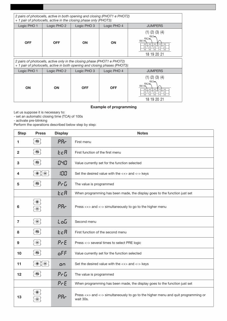
2 pairs of photocells, active in both opening and closing (PHOT1 e PHOT2) + 1 pair of photocells, active in the closing phase only (PHOT3):
Example of programmingLet us suppose it is necessary to:- set an automatic closing time (TCA) of 100s - activate pre-blinking Perform the operations described below step by step:
Step Press Display Notes
1 PAR First menu
2 TCA First function of the first menu
3 040 Value currently set for the function selected
4 100 Set the desired value with the <+> and <-> keys
5 PRG The value is programmed
TCA When programming has been made, the display goes to the function just set
6 PAR Press <+> and <-> simultaneously to go to the higher menu
7 Log Second menu
8 TCA First function of the second menu
9 Pre Press <-> several times to select PRE logic
10 OFF Value currently set for the function selected
11 ON Set the desired value with the <+> and <-> keys
12 PRG The value is programmed
Pre When programming has been made, the display goes to the function just set
13 PARPress <+> and <-> simultaneously to go to the higher menu and quit programming or wait 30s.
nihalcavdar
Text Box
İlk menü
nihalcavdar
Text Box
İlk menünün ilk fonksiyonu
nihalcavdar
Text Box
Seçilen fonksiyon için ayarlanan değer
nihalcavdar
Text Box
Programlama örneği
nihalcavdar
Text Box
Farzedelim ki: - 100 değerlerinde bir otomatik kapama zamanı (TCA) setlemek, - ön yanıp sönme işlemini aktive etmek gerekiyor. Aşağıda anlatılan işlemleri adım adım yapın:
nihalcavdar
Text Box
Adım
nihalcavdar
Text Box
Tuş
nihalcavdar
Text Box
Gösterge
nihalcavdar
Text Box
Notlar
nihalcavdar
Text Box
İstenilen değeri <+> ve <-> tuşlarını kullanarak ayarlayın
nihalcavdar
Text Box
Değer programlanmıştır
nihalcavdar
Text Box
Programlama tamamlandığında gösterge yeni setlenen fonksiyona döner
nihalcavdar
Text Box
Bir üst menüye gitmek için <+> ve <-> ye aynı anda basın
nihalcavdar
Text Box
İkinci menü
nihalcavdar
Text Box
İkinci menünün ilk fonksiyonu
nihalcavdar
Text Box
Seçilen fonksiyon için önceden setlenmiş değer
nihalcavdar
Text Box
ÖN lojiği seçmek için <-> e bir kaç kez basın
nihalcavdar
Text Box
Değer programlanmıştır
nihalcavdar
Text Box
İstenilen değeri <+> ve <-> düğmeleriyle ayarlayın
nihalcavdar
Text Box
Programlama tamamlandığında gösterge yeni setlenen fonksiyona döner
nihalcavdar
Text Box
Bir üst menüye gitmek için <+> ve <-> ye aynı anda basın ve programlamadan çıkın yada 30 saniye bekleyin
nihalcavdar
Text Box
2 çift fotosel, sadece kapama durumunda aktif (PHOT1 ve PHOT2) + 1 çift fotosel, hem açma hem kapama durumunda aktif (PHOT3)
nihalcavdar
Text Box
2 çift fotosel, hem açma hem kapama durumunda aktif (PHOT1 ve PHOT2) + 1 çift fotosel, sadece kapama durumunda aktif (PHOT3)
nihalcavdar
Text Box
Lojik
nihalcavdar
Text Box
Lojik
nihalcavdar
Text Box
Lojik
nihalcavdar
Text Box
Lojik
nihalcavdar
Text Box
Lojik
nihalcavdar
Text Box
Lojik
nihalcavdar
Text Box
Lojik
nihalcavdar
Text Box
Lojik
nihalcavdar
Text Box
nihalcavdar
Text Box
Teknik3
Text Box
KURULUM KILAVUZU
Teknik3
Text Box
TÜRKÇE
nihalcavdar
Text Box
L8542302 - ver.01 - 9
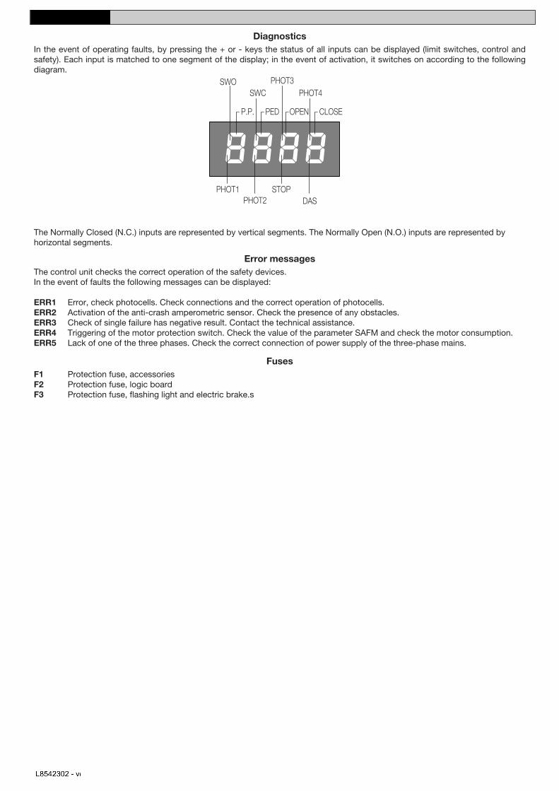
DiagnosticsIn the event of operating faults, by pressing the + or - keys the status of all inputs can be displayed (limit switches, control and safety). Each input is matched to one segment of the display; in the event of activation, it switches on according to the following diagram.
�����
���
����
��� ����������
����� ���
���� ��� ���� �����
The Normally Closed (N.C.) inputs are represented by vertical segments. The Normally Open (N.O.) inputs are represented by horizontal segments.
Error messages The control unit checks the correct operation of the safety devices. In the event of faults the following messages can be displayed:
ERR1 Error, check photocells. Check connections and the correct operation of photocells.ERR2 Activation of the anti-crash amperometric sensor. Check the presence of any obstacles.ERR3 Check of single failure has negative result. Contact the technical assistance. ERR4 Triggering of the motor protection switch. Check the value of the parameter SAFM and check the motor consumption.ERR5 Lack of one of the three phases. Check the correct connection of power supply of the three-phase mains.
Fuses F1 Protection fuse, accessories F2 Protection fuse, logic board F3 Protection fuse, flashing light and electric brake.s
nihalcavdar
Text Box
Sigortalar F1 Koruma sigortası, aksesuarlar F2 Koruma sigortası, lojik kart F3 Koruma sigortası, flaşör lamba ve elektrikli fren
nihalcavdar
Text Box
Hata mesajları Kontrol ünitesi, güvenlik cihazlarının doğru çalışıp çalışmadığını kontrol eder. Hata durumlarında aşağıdaki mesajlar görüntülenebilir: ERR1 Hata, fotoselleri kontrol edin. Bağlantıları ve fotosellerin doğru çalışıp çalışmadığını kontrol edin. ERR2 Akım algılama metodu ile engel tanıma özelliğinin aktivasyonu. Bir engel olup olmadığını kontrol edin. ERR3 Hata kontrolü negatif sonuçlandı. Teknik personelle görüşün. ERR4 Motor koruma switch'inin tetiklendi. SAFM parametresinin değerini ve motor sarfiyatını kontrol edin. ERR5 Üç fazdan biri eksik. Üç fazlı güç kaynağının bağlantılarını kontrol edin.
nihalcavdar
Text Box
Normalde Kapalı girişler (N.C.) dikey parçalarla, Normalde Açık girişler (N.O.) yatay parçalarla gösterilmiştir.
nihalcavdar
Text Box
Hata Göstergeleri İşlem hataları durumunda, + veya- tuşlarına basarak tüm girişlerin durumu görüntülenebilir (limit switch'ler, kontrol ve güvenlik). Her giriş göstergenin bir parçasına denk düşer, aktive edildiğinde aşağıdaki şekilde belirtildiği gibi açılır.
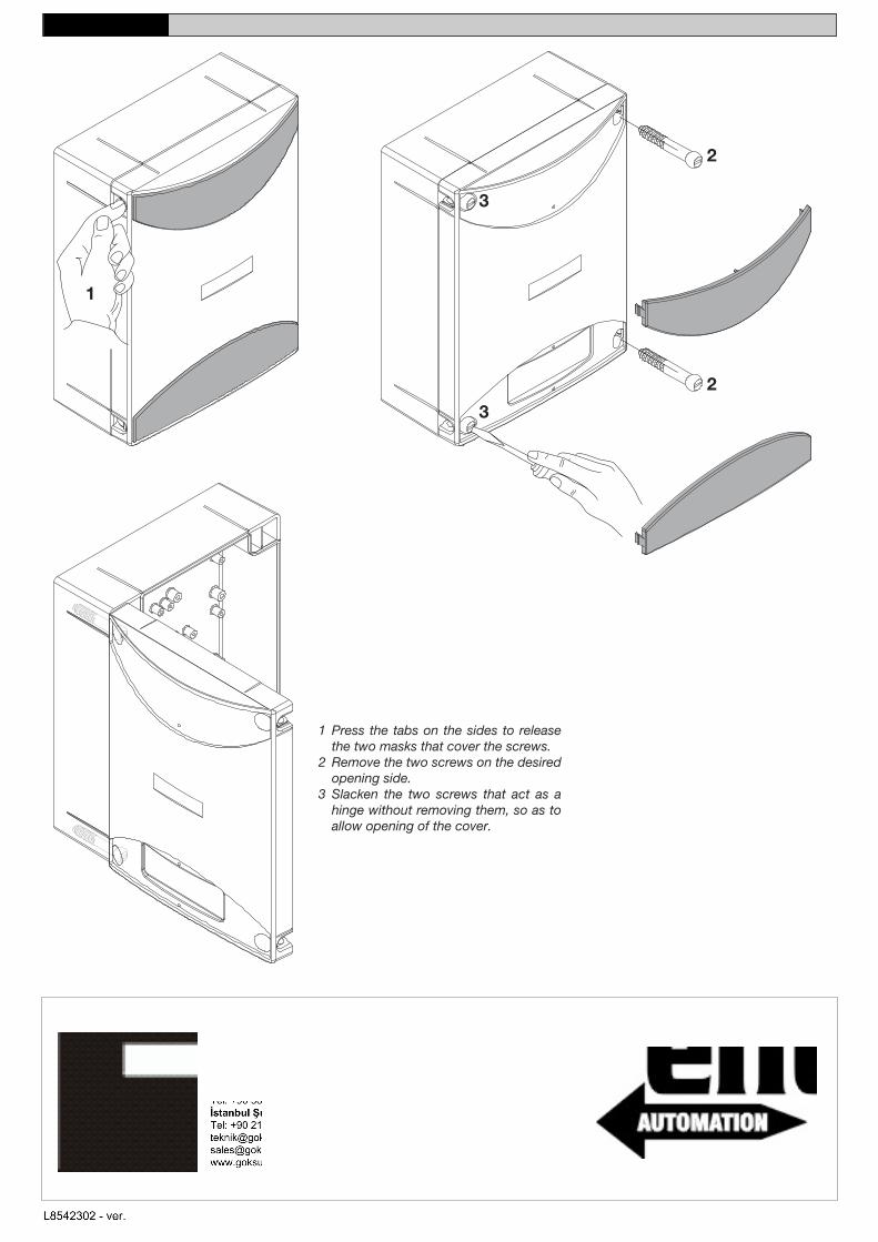
1 Vidaları kapatan iki kapağı açmak için yanlarda bulunan girintilere bastırın 2 Açmak istediğiniz taraftaki iki vidayı sökün 3 Kapağı açabilmak için, menteşe görevi gören iki vidayı çıkarmadan gevşetin.
Teknik3
Text Box
KURULUM KILAVUZU
Teknik3
Text Box
TÜRKÇE
nihalcavdar
Stamp
Teknik3
Text Box
GÖKSU YAPI TEKNOLOJİLERİ A.Ş Genel Müdürlük / Head Office: Uzayçağı Caddesi No:62/2 Ostim Organize Sanayi Bölgesi 06370 ANKARA Tel: +90 312 386 03 03 Fax: +90 312 386 03 33 Fabrika / Factory: Tel: +90 382 266 23 20 Fax: +90 382 266 23 22 İstanbul Şube/ Branch: Tel: +90 212 210 49 90 Fax: +90 212 210 49 89 [email protected][email protected] www.goksugroup.com.tr