Embed Size (px)
Citation preview

888-45-221-W-04 rev.L • 04/151 of 17
Interactive TV Arm: 45-296-026: OM1100549User's Guide
Guía del usuario
Manuel de l’utilisateur
Benutzerhandbuch
Gebruikersgids
Guida per l’utente
Användarguide
ユーザーガイド用户指南
사용자 안내서
CAUTION!MAXIMUM SCREEN SIZE
CAUTION!MAXIMUM WEIGHT CAPACITY
40 LBS18.1 KG
55"
User's Guide - EnglishGuía del usuario - EspañolManuel de l’utilisateur - FrançaisGebruikersgids - NederlandsBenutzerhandbuch - DeutschGuida per l’utente - ItalianoAnvändarhandbok - svenskaユーザーガイド : 日本語用户指南 : 汉语
www.ergotron.com
Important! You will need to adjust this product after installation is complete. Make sure all your equipment is properly installed on the product before attempting adjustments. This product should move smoothly and easily through the full range of motion and stay where you set it. If movements are too easy or diffi cult or if product does not stay in desired positions, follow the adjustment instructions to create smooth and easy movements. Depending on your product and the adjustment, it may take many turns to notice a diff erence. Any time equipment is added or removed from this product, resulting in a change in the weight of the mounted load, you should repeat these adjustment steps to ensure safe and optimum operation.

888-45-221-W-04 rev.L • 04/152 of 17
CONTENTSPart Quantity Description
1 1 Wall Plate
2 1 Arm/Wall Plate Hardware
3 2 Wall Plate Covers
4 1 Rear Arm Cover
5 1 CFT Arm
6 1 200x200 VESA Monitor Plate
7 4 Spider Adapters
1
2
3
4
5 6
7
P-F
P-J
P-K
Wall Kit ST8x2 697-641-00Part Quantity Description
W-A 2 Lag Bolt
W-B 2 Round Washers
W-C 2 Wall Anchor
Specialty Hardware kit 697-640-00Part Quantity Description
P-A 1 Philips Screw
P-B 4 Round Head Screws
P-C 8 Nuts
Screws/Hardware For Flat Panel 697-613-00Part Quantity Description
M-A 4 Philips screws M4 x 15mm
M-B 4 Philips screws M4 x 30mm
M-C 4 Philips screws M5 x 15mm
M-D 4 Philips screws M5 x 30mm
M-E 4 Philips screws M6 x 15mm
M-F 4 Philips screws M6 x 30mm
M-G 4 Philips screws M8 x 15mm
M-H 4 Philips screws M8 x 30mm
M-I 4 Round spacers M6-M8 x 5mm
M-J 4 Round spacers M6-M8 x 10mm
M-K 4 Round washers M4-M5
M-L 4 Round washers M6-M8
P-IP-HP-G
P-M
Cable Wrap Kit 697-701Part Quantity Description
P-D 1 Cable Wrap
BOP 699-633Part Quantity Description
P-L 2 Zip Ties P-Q8mm1/4” Drive

888-45-221-W-04 rev.L • 04/153 of 17
CAUTION!MAXIMUM SCREEN SIZE
CAUTION!MAXIMUM WEIGHT CAPACITY
40 LBS18.1 KG
55”Tools NeededHerramientas necesariasOutils requisBenötigte WerkzeugeBenodigde gereedschappenStrumenti necessariPotrzebne narzędziaPotřebné nástrojeSzükséges eszközökΑπαιτούμενα εργαλείαFerramentas necessáriasNødvendigt værktøjTarvittavat työkalutVerktyg som krävsInstrumente necesareНеобходими уредиVajalikud tööriistadNepieciešamie rīkiReikalingi įrankiaiPotrebno orodjePotrebné náradieНеобходимые инструментыGerekli AletlerNødvendige verktøyةمزاللا تاودألا需要的工具必要なツール
TOOLS NEEDED
13mm and 8mm
7/32"
(2 3/4")70mm
(7/32")5.5m
m

888-45-221-W-04 rev.L • 04/154 of 17
1 1. MOUNTING CONSIDERATIONS:
• Wall Mount Bracket MUST be attached to a stud or solid concrete. DO NOT attach this product to hollow wall or any other confi guration.
• Make sure Arm will have desired unobstructed range of motion: up-down, side-to-side, in-out (see section RANGE OF MOTION).• Make sure cables will reach their destinations with enough remaining slack to allow Arm full range of motion.• Use the RANGE OF MOTION section to familiarize yourself with the movements of this product. Take into account that the TV will
change location from Side-to-Side when pulled out from the wall.• Use the SPACE REQUIREMENTS section for maximum measurements of this products full range of motion.• If there is no available stud for desired TV location, you may want to insert horizontal studs into your wall at the desired mounting
location (see “Horizontal Studs” image below).
2. CHOOSE YOUR DESIRED TV LOCATIONS:
Choose your desired TV locations when stowed and extended. Note the TV will move side-to-side when pushing it into and pulling it out from the wall as well as lifting it up and lowering it down. This step requires an understanding of this products Range of Motion (see section RANGE OF MOTION).
3. CHOOSE AN AVAILABLE WALL MOUNTING LOCATION:
Find an available stud or area of solid concrete to attach the Wall Mount Bracket to that will allow your TV to be stowed and extended as desired.Place the Template on the wall. When the Wall Mount Bracket on the Template is lined up with the mounting location on the wall (stud or concrete), the ‘TV ARC’ lines will show you the available locations of the center of your TV when stowed against the wall.Once you’ve lined up the mounting location to a stud or solid concrete that will place your TV in your desired locations, use a punch to mark your wall at the 2 Mounting Hole locations on the Template. Then remove the template from the wall.
INSTRUCTIONS
RANGE OF MOTION
SPACE REQUIREMENTS
front
front front front
front
front
side side side
side
top
top top top
top
Horizontal Studs
Arm Fully Extended from Wall
Full Up
Full Up
Full Up
In the Center
In the Center
In the Center
Full Down
Full Down
Full Down
Arm Flat Against Wall (to the left)
Arm Flat Against Wall (to the right)
Distance from the Wall
If there is no available stud for desired TV location, you may want to insert horizontal studs into your wall at the desired mounting location.
24.5” (622 mm) + Thickness of TV
18.19” (462 mm) + Thickness of TV
Horizontal Space Requirements33.76” (858 mm) + Width of TV*
Vertical Space Requirements20” (508 mm) + Height of TV*
*Space requirement dimensions assume mounting holes are centered on the TV.
frontside topfrontside topfrontside top
frontside top frontside top frontside top

888-45-221-W-04 rev.L • 04/155 of 17
2
3
a
a
b c
c d
W-A
W-B
1
b
7/32 x 2.75"5.5mm x 70mm
Wood Stud Mount

888-45-221-W-04 rev.L • 04/156 of 17
2a b c
3a
c
b
d
W-A
W-B
W-C
3/8 x 2.75"9.5 - 10mm x 70mm
Solid Wall Mount

888-45-221-W-04 rev.L • 04/157 of 17
4 a b
c d
1
25P-F
P-J
P-K
P-I16mm Bearing
P-G25mm Washer
P-M
P-F65mm Washer
P-M
P-HSpring Disc
NOTE: Part# P-H must be concave
face down for proper assembly.

888-45-221-W-04 rev.L • 04/158 of 17
5
100 x 200200 x 200
200 x 300200 x 400
300 x 300300 x 400
400 x 400
600 x 400
300 x 200
400 x 200
200mm (7-7/8”)
400mm
(15-3/4”)
300mm
(11-13/16”)
600mm (23-5/8”)
100mm
(3-15/16”)
200mm
(7-7/8”)
200mm (7-7/8”)
400mm (15-3/4”)
300mm (11-13/16”)
400mm
(15-3/4”)
300mm
(11-13/16”)
400mm
(15-3/4”)
400mm (15-3/4”)
300mm (11-13/16”)
200mm
(7-7/8”)
A
B
C
D

888-45-221-W-04 rev.L • 04/159 of 17
OROR
OR
OROR
OR
OR
100 x 200200 x 200
200mm (7-7/8”)
100mm
(3-15/16”)
200mm
(7-7/8”)
200mm (7-7/8”)
A
M-AM-B
M-CM-D
M-EM-F
M-GM-H
M-K
M-L
M-I
M-J
6
WARNING! PLEASE SELECT THE PROPER SCREW LENGTH FOR YOUR FLAT PANEL BY HAND TIGHTENING TO CHECK YOUR FLAT PANELS THREAD DEPTH.
888-45-221-W-04 rev.L • 04/1510 of 17
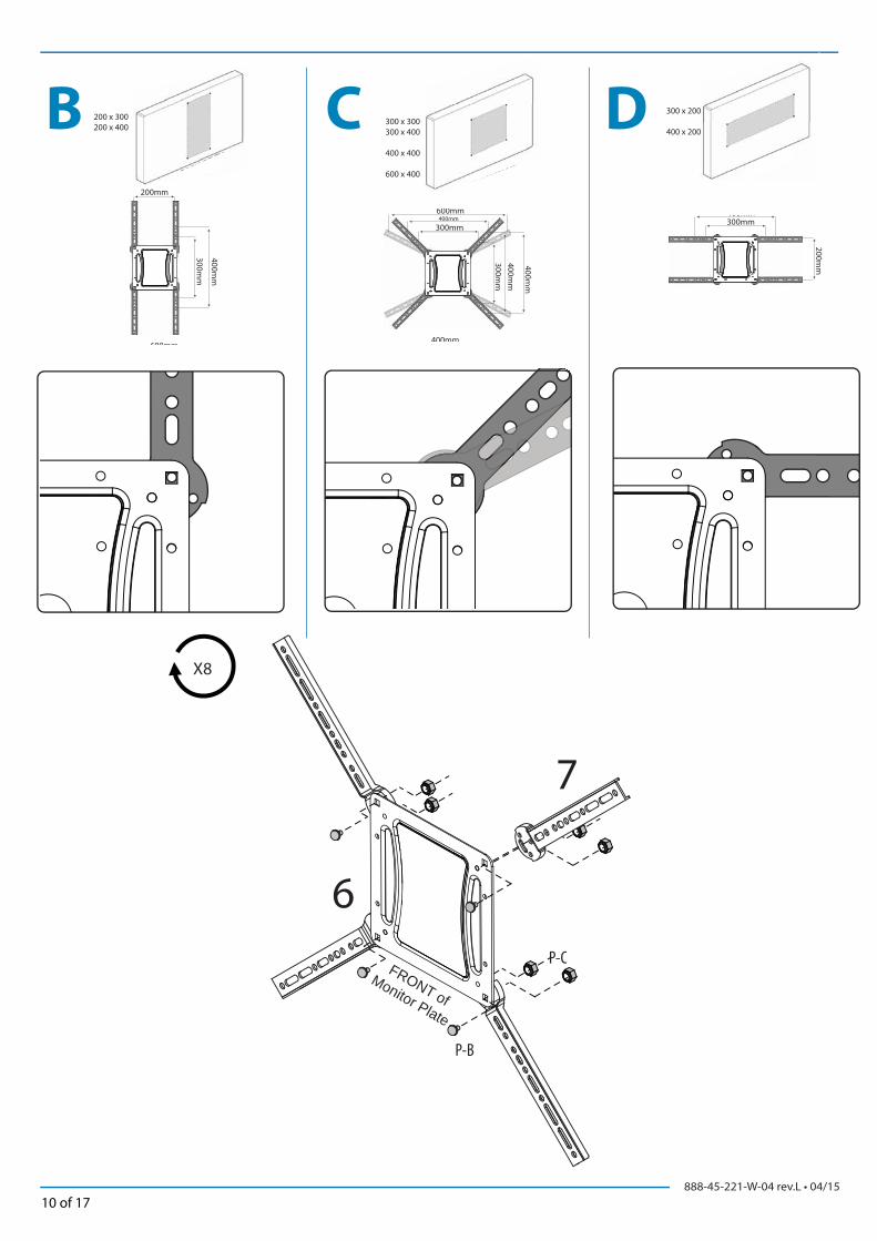
B C D
400mm
300mm
600mm
200mm
600mm 400mm
300mm
400mm
300mm
400m
m
400mm
400mm 300mm
200mm
200 x 300200 x 400
300 x 300300 x 400
400 x 400
600 x 400
300 x 200
400 x 200
X8
P-B
P-C
6
7
FRONT of Monitor Plate

888-45-221-W-04 rev.L • 04/1511 of 17
UP
OROR
OR
OROR
OR
OR
OR
B / C / D
M-AM-B
M-C
M-D
M-EM-F
M-GM-H
M-K
M-L
M-I
M-J
WARNING! PLEASE SELECT THE PROPER SCREW LENGTH FOR YOUR FLAT PANEL BY HAND TIGHTENING TO CHECK YOUR FLAT PANELS THREAD DEPTH.

888-45-221-W-04 rev.L • 04/1512 of 17
P-A
P-D
P-L
6
7 NOTE: Leave enough slack in cable to allow full range of motion.
Caution: To avoid the potential to pinch cables it is important to follow the cable routing
instructions in this manual. Failure to follow these instructions may result in equipment
damage or personal injury.

888-45-221-W-04 rev.L • 04/1513 of 17
a bLift – Up and down
Elevación (arriba y abajo)
Ajustement en hauteur : bas et haut
Höhenverstellung – rauf und runter
Verstel in hoogte – Omhoog en omlaag
Sollevamento – Su e Giù
Lyft – upp och ned
リフト(上下)升降(上下)높이 (위/아래로)
dTilt – Forward and Backward
Inclinación (adelante y atrás)
Inclinaison : Avant et arrière
Neigung – vor und zurück
Kantel – Naar voren en naar achteren
Inclinazione – Avanti ed Indietro
Vinkla – framåt och bakåt
チルト (前後)倾斜(前后)기울기 – 앞/뒤로
c
8 Adjustment Step
Important! You will need to adjust this product after installation is complete. Make sure all your equipment is properly installed on the product before attempting adjustments. This product should move smoothly and easily through the full range of motion and stay where you set it. If movements are too easy or diffi cult or if product does not stay in desired positions, follow the adjustment instructions to create smooth and easy movements. Depending on your product and the adjustment, it may take many turns to notice a diff erence. Any time equipment is added or removed from this product, resulting in a change in the weight of the mounted load, you should repeat these adjustment steps to ensure safe and optimum operation.

888-45-221-W-04 rev.L • 04/1514 of 17
a Lift – Up and down
Elevación (arriba y abajo)
Ajustement en hauteur : bas et haut
Höhenverstellung – rauf und runter
Verstel in hoogte – Omhoog en omlaag
Sollevamento – Su e Giù
Lyft – upp och ned
リフト(上下)升降(上下)높이 (위/아래로)
8 mm
1/4” Drive
P-Q
Increase Lift StrengthIf the mounted weight is too heavy or this product does not stay up when raised, then you'll need to increase Lift Strength:
Decrease Lift StrengthIf the mounted weight is too light or this product does not stay down when lowered, then you'll need to decrease Lift Strength:

888-45-221-W-04 rev.L • 04/1515 of 17
b
1
3
2
Increase FrictionIf this product moves too easily from side-to-side, then you'll need to increase friction:
Decrease FrictionIf this product is too diffi cult to move from side-to-side, then you'll need to decrease friction:

888-45-221-W-04 rev.L • 04/1516 of 17
c
1 2
CAUTION! The bottom nut will turn during adjustment of the top nut; DO NOT apply any tool to the bottom nut. Serious damage to the Arm may occur if these instructions are not followed.
PRECAUCIÓN La tuerca inferior gira mientras se ajusta la tuerca supe-rior; NO aplique ninguna herramienta a la tuerca inferior. Si no sigue estas instrucciones, el brazo puede sufrir daños graves.
ATTENTION ! L’écrou du bas tournera pendant l’ajustement de celui du haut ; n’utiliser AUCUN outil sur l’écrou du bas. Le bar pourrait être sérieusement endommagé dans le cas où ces instructions ne seraient pas suivies.
VORSICHT! Beim Drehen der oberen Mutter dreht sich auch die untere Mutter. Fixieren Sie die untere Mutter AUF KEINEN FALL. Bei Nichteinhaltung dieser Anweisung kann es zu erheblichen Schäden am Arm kommen.
VOORZICHTIG! Tijdens het aanpassen van de bovenste moer draait de onderste moer mee. GEBRUIK GEEN GEREEDSCHAP op de onderste moer. Er kan ernstige schade aan de arm optreden als deze instructies niet opgevolgd worden.
ATTENZIONE Il dado inferiore gira durante la regolazione del dado superiore; NON applicare nessun attrezzo al dado inferiore. Se non si seguono queste istruzioni, si possono causare danni gravi al braccio.
VARNING: Den undre muttern kommer att rotera under justering av den övre muttern – använd INTE något verktyg på den undre muttern. Det kan uppstå allvarliga skador på armen om dessa instruktioner inte åtföljs.
注意! 上部のナットを調節する際に下部のナットも回転します。下部のナットには、工具などを一切使用しないでください。 この指示を無視すると、アームに重大な損傷を与える可能性があります。小心! 调整上端螺母时底部螺母将会转动;请勿在底部螺母上使用任何工具。 不遵守此指示可能导致支臂严重损坏。
3 Increase FrictionIf this product moves too easily from side-to-side, then you'll need to increase friction:
Decrease FrictionIf this product is too diffi cult to move from side-to-side, then you'll need to decrease friction:

888-45-221-W-04 rev.L • 04/1517 of 17
dTilt – Forward and Backward
Inclinación (adelante y atrás)
Inclinaison : Avant et arrière
Neigung – vor und zurück
Kantel – Naar voren en naar achteren
Inclinazione – Avanti ed Indietro
Vinkla – framåt och bakåt
チルト (前後)倾斜(前后)기울기 – 앞/뒤로