Embed Size (px)
Citation preview
HAGLÖF SWEDEN AB
Vertex IV and Transponder T3 manual January 2007, v.1.0
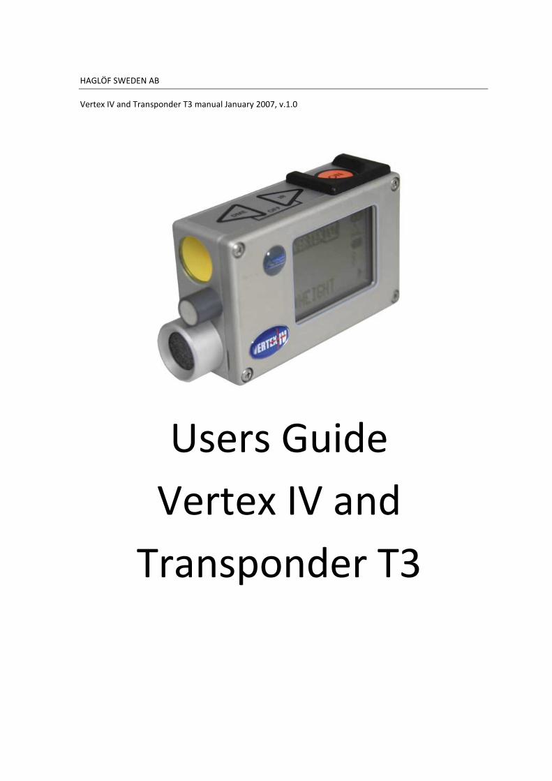
Users Guide
Vertex IV and
Transponder T3
Vertex IV and Transponder T3 manual v.1.0 eng
© 2007 Haglöf Sweden AB 2
Users Guide
Vertex IV and
Transponder T3
2007-02-02/rev. 2007-09-01
Haglöf Sweden AB Box 28 • 88221 Långsele • Sweden
Phone: +46 620-255 80 • Fax: +46 620-205 81 • Mail: [email protected]
Web: www.haglofsweden.com
Vertex IV and Transponder T3 manual v.1.0 eng
© 2007 Haglöf Sweden AB 3
Vertex IV and Transponder T3 manual v.1.0 eng
© 2007 Haglöf Sweden AB 4
VERTEX IV ................................................................................................................... 6
FUNCTIONS AND CONSTRUCTION ........................................................................................ 6
DESCRIPTION ............................................................................................................... 7
KEYS ............................................................................................................................ 7
FUNCTION OF THE ARROW KEYS .......................................................................................... 7
THE ON KEY FUNCTION ..................................................................................................... 8
RED CROSS AIM ........................................................................................................... 8
LOUD SPEAKERS .......................................................................................................... 8
BATTERY ...................................................................................................................... 8
MENU OVERVIEW ............................................................................................................. 9
IMPORTANT FACTS ON YOUR VERTEX IV INSTRUMENT ............................................. 10
SETTINGS ................................................................................................................... 11
SETUP ......................................................................................................................... 11
METRIC/FEET .............................................................................................................. 11
DEG/GRAD/% ............................................................................................................. 11
P.OFFSET (PIVOT OFFSET) .............................................................................................. 11
T.HEIGHT (TRANSPONDER HEIGHT) .................................................................................. 12
M.DIST (MANUAL DISTANCE) ........................................................................................... 12
BAF BASAL AREA FACTOR ................................................................................................ 12
CALIBRATE ................................................................................................................. 13
DISPLAY ...................................................................................................................... 13
CONTRAST .................................................................................................................. 13
CROSS HAIR SIGHT ...................................................................................................... 13
HOW TO USE THE VERTEX IV ...................................................................................... 14
HEIGHT ....................................................................................................................... 14
HEIGHT MEASURING WITH TRANSPONDER ............................................................................ 14
HEIGHT MEASURING WITHOUT THE TRANSPONDER ............................................................... 14
HEIGHT MEASURING FROM HORIZONTAL LINE ....................................................................... 15
INCLINATION (ANGLE) .................................................................................................... 15
DISTANCE MEASURING (DME).......................................................................................... 16
Vertex IV and Transponder T3 manual v.1.0 eng
© 2007 Haglöf Sweden AB 5
DISTANCE MEASURING WITH THE ADAPTER FOR 360 DEGREES ................................................ 16
HORIZONTAL DISTANCE MEASURING (DME) ........................................................................ 16
BAF – SMALLEST DIAMETER ............................................................................................. 17
DIAMETERS IN LEANING TERRAIN ........................................................................................ 17
TRANSPONDER T3 ..................................................................................................... 18
HOW TO USE THE T3 TRANSPONDER ................................................................................... 18
BLUETOOTH ............................................................................................................... 19
BLUETOOTH PORTS IN COMMON COMPUTER DEVICES ............................................................. 19
The Allegro ............................................................................................................ 19
The Recon .............................................................................................................. 19
DATA FORMAT ............................................................................................................... 20
Height Measuring .................................................................................................. 20
Distance Measuring ............................................................................................... 20
SIGN FORMAT BLUETOOTH ............................................................................................... 20
EXAMPLE OF CONNECTION TO PC ...................................................................................... 21
IR ............................................................................................................................... 22
SIGN FORMAT IR ............................................................................................................ 22
TECHNICAL SPECIFICATION ........................................................................................ 23
FAULT DETECTION ..................................................................................................... 24
QUICK START GUIDE .................................................................................................. 25
HEIGHT MEASURING WHEN USING THE TRANSPONDER ............................................................ 25
HEIGHT MEASURING WITHOUT USING THE TRANSPONDER ....................................................... 25
HEIGHT MEASURING HORIZONTALLY .................................................................................... 25
ANGLE MEASURING ....................................................................................................... 25
DISTANCE MEASURING (DME) ....................................................................................... 25
TURN ON AND TURN OFF THE TRANSPONDER T3 .................................................................... 25
DECLARATION OF CONFORMITY ................................................................................ 26
WARRANTY AND SERVICE INFORMATION ............................................................................. 26
SOFTWARE ................................................................................................................. 27
Vertex IV and Transponder T3 manual v.1.0 eng
© 2007 Haglöf Sweden AB 6
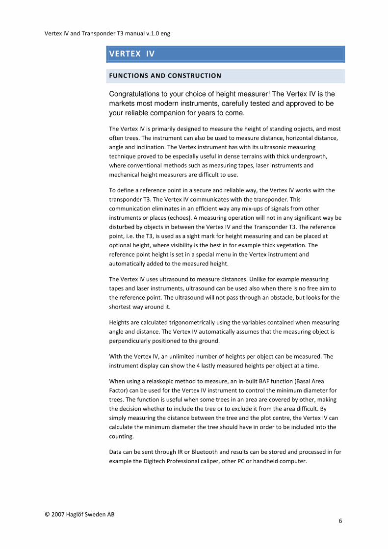
VERTEX IV
FUNCTIONS AND CONSTRUCTION
Congratulations to your choice of height measurer! The Vertex IV is the
markets most modern instruments, carefully tested and approved to be
your reliable companion for years to come.
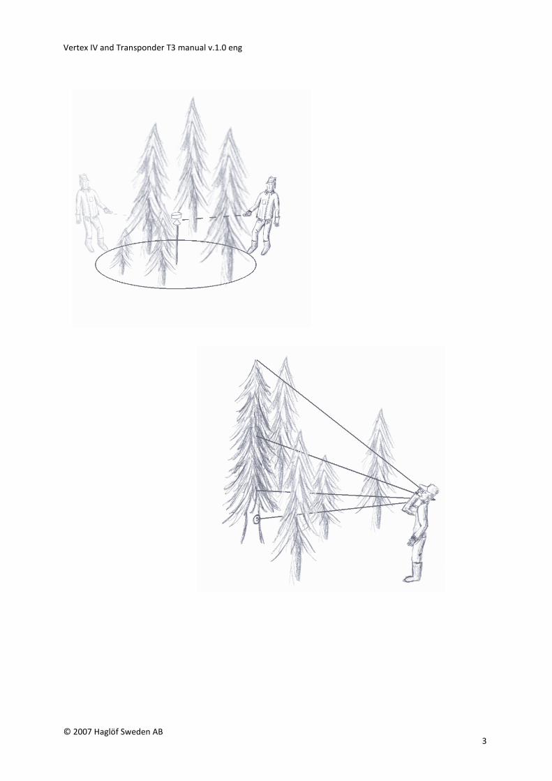
The Vertex IV is primarily designed to measure the height of standing objects, and most
often trees. The instrument can also be used to measure distance, horizontal distance,
angle and inclination. The Vertex instrument has with its ultrasonic measuring
technique proved to be especially useful in dense terrains with thick undergrowth,
where conventional methods such as measuring tapes, laser instruments and
mechanical height measurers are difficult to use.
To define a reference point in a secure and reliable way, the Vertex IV works with the
transponder T3. The Vertex IV communicates with the transponder. This
communication eliminates in an efficient way any mix-ups of signals from other
instruments or places (echoes). A measuring operation will not in any significant way be
disturbed by objects in between the Vertex IV and the Transponder T3. The reference
point, i.e. the T3, is used as a sight mark for height measuring and can be placed at
optional height, where visibility is the best in for example thick vegetation. The
reference point height is set in a special menu in the Vertex instrument and
automatically added to the measured height.
The Vertex IV uses ultrasound to measure distances. Unlike for example measuring
tapes and laser instruments, ultrasound can be used also when there is no free aim to
the reference point. The ultrasound will not pass through an obstacle, but looks for the
shortest way around it.
Heights are calculated trigonometrically using the variables contained when measuring
angle and distance. The Vertex IV automatically assumes that the measuring object is
perpendicularly positioned to the ground.
With the Vertex IV, an unlimited number of heights per object can be measured. The
instrument display can show the 4 lastly measured heights per object at a time.
When using a relaskopic method to measure, an in-built BAF function (Basal Area
Factor) can be used for the Vertex IV instrument to control the minimum diameter for
trees. The function is useful when some trees in an area are covered by other, making
the decision whether to include the tree or to exclude it from the area difficult. By
simply measuring the distance between the tree and the plot centre, the Vertex IV can
calculate the minimum diameter the tree should have in order to be included into the
counting.
Data can be sent through IR or Bluetooth and results can be stored and processed in for
example the Digitech Professional caliper, other PC or handheld computer.
Vertex IV and Transponder T3 manual v.1.0 eng
© 2007 Haglöf Sweden AB 7
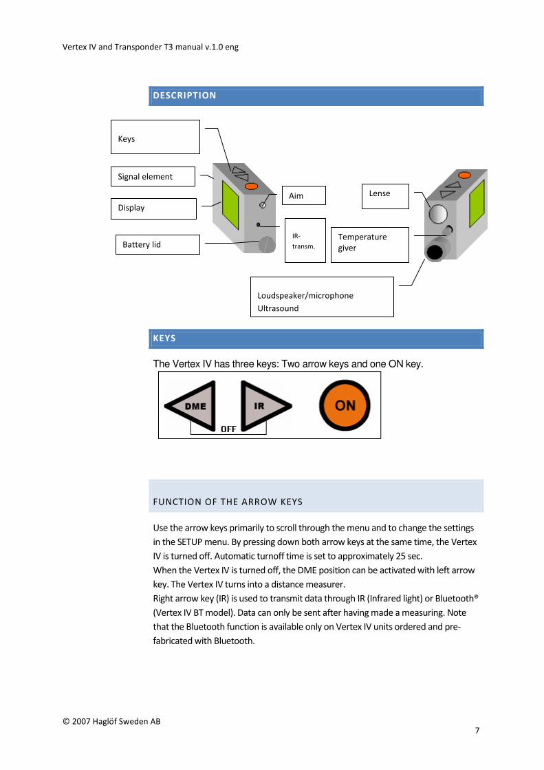
DESCRIPTION
KEYS
The Vertex IV has three keys: Two arrow keys and one ON key.
FUNCTION OF THE ARROW KEYS
Use the arrow keys primarily to scroll through the menu and to change the settings
in the SETUP menu. By pressing down both arrow keys at the same time, the Vertex
IV is turned off. Automatic turnoff time is set to approximately 25 sec.
When the Vertex IV is turned off, the DME position can be activated with left arrow
key. The Vertex IV turns into a distance measurer.
Right arrow key (IR) is used to transmit data through IR (Infrared light) or Bluetooth®
(Vertex IV BT model). Data can only be sent after having made a measuring. Note
that the Bluetooth function is available only on Vertex IV units ordered and pre-
fabricated with Bluetooth.
Battery lid IR-
transm.
Aim
Display
Keys
Loudspeaker/microphone
Ultrasound
Temperature giver
Lense
Signal element
Vertex IV and Transponder T3 manual v.1.0 eng
© 2007 Haglöf Sweden AB 8
THE ON KEY FUNCTION
The ON key is used to start the Vertex IV, to confirm a value and as a trigger
when measuring heights and angles.
RED CROSS AIM
The red dot cross hair sight simplifies spotting the target and holding the
instrument straight when measuring heights, for best possible accuracy.
For best possible visibility, the light can be adjusted with the left arrow key
when aiming.
LOUD SPEAKERS
The Vertex IV is equipped with a built-in signal that will beep when an angle
or a height has been registered.
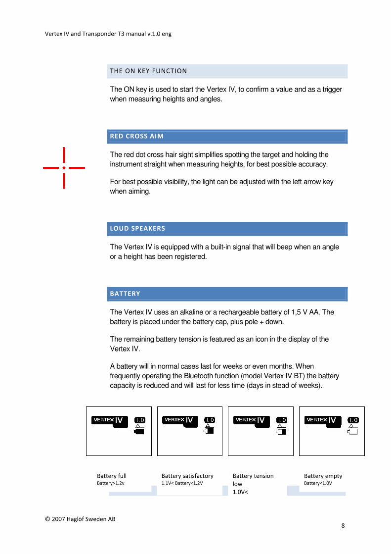
BATTERY
The Vertex IV uses an alkaline or a rechargeable battery of 1,5 V AA. The
battery is placed under the battery cap, plus pole + down.
The remaining battery tension is featured as an icon in the display of the
Vertex IV.
A battery will in normal cases last for weeks or even months. When
frequently operating the Bluetooth function (model Vertex IV BT) the battery
capacity is reduced and will last for less time (days in stead of weeks).
Battery full Battery>1.2v
Battery empty Battery<1.0V
Battery satisfactory 1.1V< Battery<1.2V
Battery tension
low
1.0V<
Vertex IV and Transponder T3 manual v.1.0 eng
© 2007 Haglöf Sweden AB 9
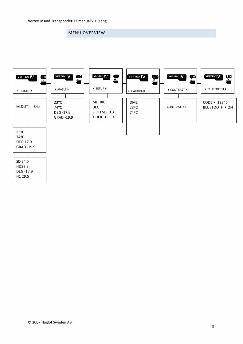
MENU OVERVIEW
�HEIGHT�
M.DIST 34.5
23ºC
74ºC
DEG-17.9
GRAD -19.9
SD 34.5
HD32.3
DEG -17.9
H1 29.5
� CALIBRATE �
DME
23ºC
74ºC
�SETUP�
METRIC
DEG
P.OFFSET 0.3
T.HEIGHT 1.3
�CONTRAST� �ANGLE� �BLUETOOTH�
CONTRAST 48
23ºC
74ºC
DEG -17.9
GRAD -19.9
CODE� 12345
BLUETOOTH�ON
Vertex IV and Transponder T3 manual v.1.0 eng
© 2007 Haglöf Sweden AB 10
IMPORTANT FACTS ON YOUR VERTEX IV INSTRUMENT
The Vertex IV uses ultra sonic signals to determine distances. Humidity, air
pressure, surrounding noise and, above all, the temperature can affect the range and extension of the ultra sonic signals. The Vertex IV has a built-in
temperature sensor that automatically compensates for the divergence caused
by variations in temperature.
In some cases, distances of 50 meters/yds and greater can be measured
without problems, and in other cases, the maximum distance can be shorter
than 30 meters/yds.
To increase and optimize the measuring accuracy, the instrument should be calibrated on a regular basis. When calibrating, it is of utmost importance that
the instrument has been given enough time to stabilize at ambient
temperature.
If, for example, the instrument is carried in an inner pocket, it can take up to 10
minutes before it has adjusted to current outdoor temperature. The
measurement inaccuracy pending on temperature is app. 2 cm/C°.
An example: Your inner pocket holds +15 C°/59F. Outdoor air temperature is -5 C°/23F.
The measurement result will show 10,40 m/34 ft and not the correct 10,00 m/32.8 ft.
The measuring fault can be made permanent if the instrument is calibrated
before reaching the correct current temperature.
-Check your instrument daily and recalibrate if necessary
-Do not touch the temperature sensor at the front of the instrument (the metal knob
between the sight and the loudspeaker)
-Never calibrate the instrument before it has reached ambient temperature
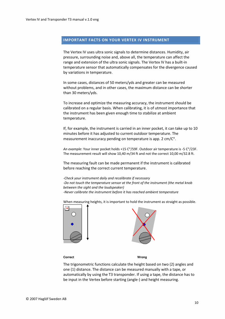
When measuring heights, it is important to hold the instrument as straight as possible.
Correct Wrong
The trigonometric functions calculate the height based on two (2) angles and
one (1) distance. The distance can be measured manually with a tape, or
automatically by using the T3 transponder. If using a tape, the distance has to
be input in the Vertex before starting (angle-) and height measuring.
Vertex IV and Transponder T3 manual v.1.0 eng
© 2007 Haglöf Sweden AB 11
SETTINGS
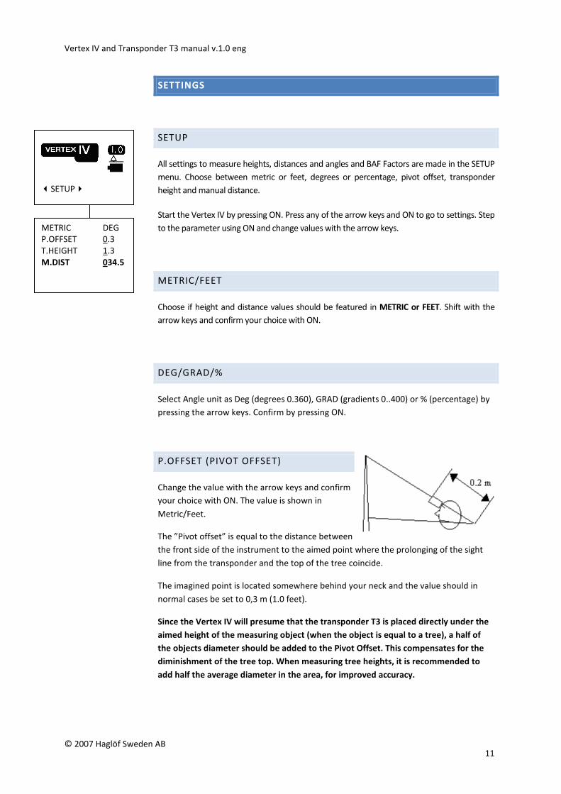
SETUP
All settings to measure heights, distances and angles and BAF Factors are made in the SETUP
menu. Choose between metric or feet, degrees or percentage, pivot offset, transponder
height and manual distance.
Start the Vertex IV by pressing ON. Press any of the arrow keys and ON to go to settings. Step
to the parameter using ON and change values with the arrow keys.
METRIC/FEET
Choose if height and distance values should be featured in METRIC or FEET. Shift with the
arrow keys and confirm your choice with ON.
DEG/GRAD/%
Select Angle unit as Deg (degrees 0.360), GRAD (gradients 0..400) or % (percentage) by
pressing the arrow keys. Confirm by pressing ON.
P.OFFSET (PIVOT OFFSET)
Change the value with the arrow keys and confirm
your choice with ON. The value is shown in
Metric/Feet.
The ”Pivot offset” is equal to the distance between
the front side of the instrument to the aimed point where the prolonging of the sight
line from the transponder and the top of the tree coincide.
The imagined point is located somewhere behind your neck and the value should in
normal cases be set to 0,3 m (1.0 feet).
Since the Vertex IV will presume that the transponder T3 is placed directly under the
aimed height of the measuring object (when the object is equal to a tree), a half of
the objects diameter should be added to the Pivot Offset. This compensates for the
diminishment of the tree top. When measuring tree heights, it is recommended to
add half the average diameter in the area, for improved accuracy.
�SETUP�
METRIC DEG
P.OFFSET 0.3
T.HEIGHT 1.3
M.DIST 034.5
Vertex IV and Transponder T3 manual v.1.0 eng
© 2007 Haglöf Sweden AB 12
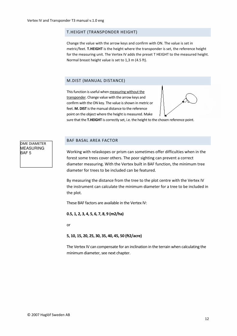
DME DIAMETER MEASURING BAF 5
T.HEIGHT (TRANSPONDER HEIGHT)
Change the value with the arrow keys and confirm with ON. The value is set in
metric/feet. T.HEIGHT is the height where the transponder is set, the reference height
for the measuring unit. The Vertex IV adds the preset T HEIGHT to the measured height.
Normal breast height value is set to 1,3 m (4.5 ft).
M.DIST (MANUAL DISTANCE)
This function is useful when measuring without the
transponder. Change value with the arrow keys and
confirm with the ON key. The value is shown in metric or
feet. M. DIST is the manual distance to the reference
point on the object where the height is measured. Make
sure that the T.HEIGHT is correctly set, i.e. the height to the chosen reference point.
BAF BASAL AREA FACTOR
Working with relaskopes or prism can sometimes offer difficulties when in the
forest some trees cover others. The poor sighting can prevent a correct
diameter measuring. With the Vertex built in BAF function, the minimum tree
diameter for trees to be included can be featured.
By measuring the distance from the tree to the plot centre with the Vertex IV
the instrument can calculate the minimum diameter for a tree to be included in
the plot.
These BAF factors are available in the Vertex IV:
0.5, 1, 2, 3, 4, 5, 6, 7, 8, 9 (m2/ha)
or
5, 10, 15, 20, 25, 30, 35, 40, 45, 50 (ft2/acre)
The Vertex IV can compensate for an inclination in the terrain when calculating the
minimum diameter, see next chapter.
Vertex IV and Transponder T3 manual v.1.0 eng
© 2007 Haglöf Sweden AB 13
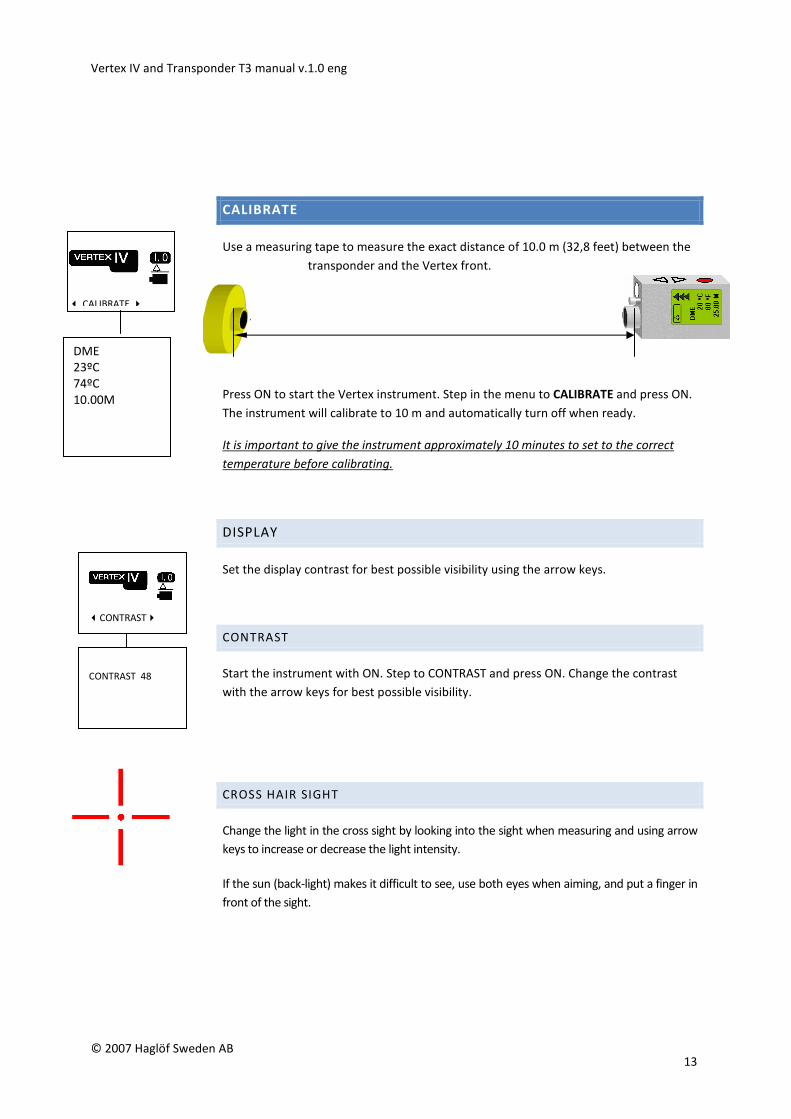
CALIBRATE
Use a measuring tape to measure the exact distance of 10.0 m (32,8 feet) between the
transponder and the Vertex front.
Press ON to start the Vertex instrument. Step in the menu to CALIBRATE and press ON.
The instrument will calibrate to 10 m and automatically turn off when ready.
It is important to give the instrument approximately 10 minutes to set to the correct
temperature before calibrating.
DISPLAY
Set the display contrast for best possible visibility using the arrow keys.
CONTRAST
Start the instrument with ON. Step to CONTRAST and press ON. Change the contrast
with the arrow keys for best possible visibility.
CROSS HAIR SIGHT
Change the light in the cross sight by looking into the sight when measuring and using arrow
keys to increase or decrease the light intensity.
If the sun (back-light) makes it difficult to see, use both eyes when aiming, and put a finger in
front of the sight.
� CALIBRATE �
DME
23ºC
74ºC
10.00M
�CONTRAST�
CONTRAST 48
Vertex IV and Transponder T3 manual v.1.0 eng
© 2007 Haglöf Sweden AB 14
HOW TO USE THE VERTEX IV
HEIGHT
Height measuring can be performed in different ways depending on type of
surroundings and operation. Heights, distance and angles can be transferred to for
example the Digitech Professional Caliper or other computer device for
storage/processing with IR or Bluetooth (Vertex IV BT model only) by pressing right
arrow key. For height measuring, the 3 last measured heights with angle and distance
can be transferred.
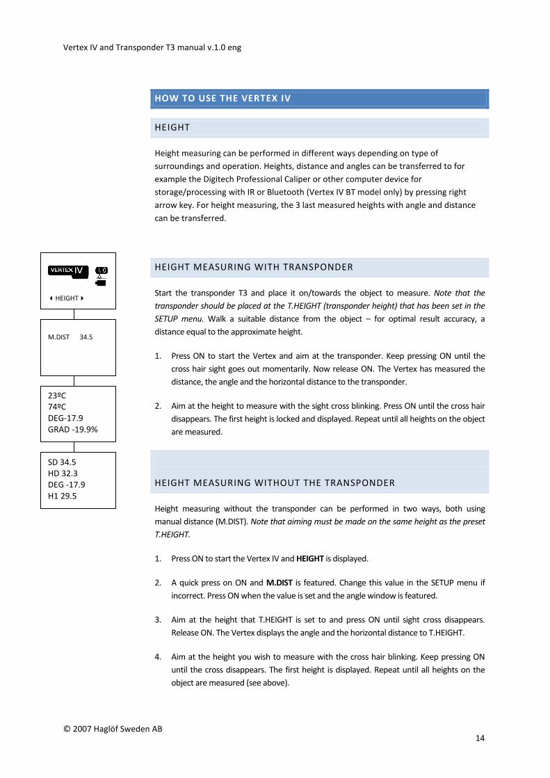
HEIGHT MEASURING WITH TRANSPONDER
Start the transponder T3 and place it on/towards the object to measure. Note that the
transponder should be placed at the T.HEIGHT (transponder height) that has been set in the
SETUP menu. Walk a suitable distance from the object – for optimal result accuracy, a
distance equal to the approximate height.
1. Press ON to start the Vertex and aim at the transponder. Keep pressing ON until the
cross hair sight goes out momentarily. Now release ON. The Vertex has measured the
distance, the angle and the horizontal distance to the transponder.
2. Aim at the height to measure with the sight cross blinking. Press ON until the cross hair
disappears. The first height is locked and displayed. Repeat until all heights on the object
are measured.
HEIGHT MEASURING WITHOUT THE TRANSPONDER
Height measuring without the transponder can be performed in two ways, both using
manual distance (M.DIST). Note that aiming must be made on the same height as the preset
T.HEIGHT.
1. Press ON to start the Vertex IV and HEIGHT is displayed.
2. A quick press on ON and M.DIST is featured. Change this value in the SETUP menu if
incorrect. Press ON when the value is set and the angle window is featured.
3. Aim at the height that T.HEIGHT is set to and press ON until sight cross disappears.
Release ON. The Vertex displays the angle and the horizontal distance to T.HEIGHT.
4. Aim at the height you wish to measure with the cross hair blinking. Keep pressing ON
until the cross disappears. The first height is displayed. Repeat until all heights on the
object are measured (see above).
�HEIGHT�
M.DIST 34.5
23ºC
74ºC
DEG-17.9
GRAD -19.9%
SD 34.5
HD 32.3
DEG -17.9
H1 29.5
Vertex IV and Transponder T3 manual v.1.0 eng
© 2007 Haglöf Sweden AB 15
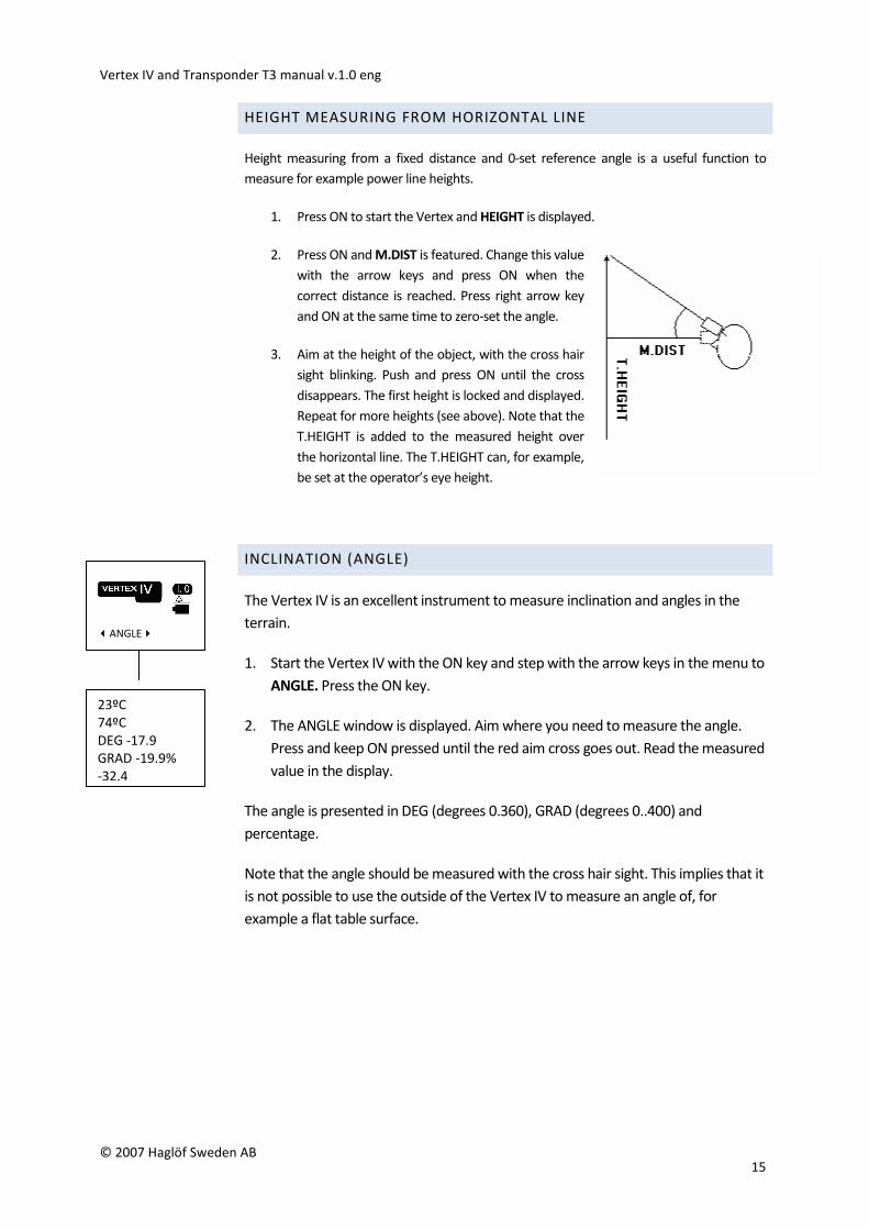
HEIGHT MEASURING FROM HORIZONTAL LINE
Height measuring from a fixed distance and 0-set reference angle is a useful function to
measure for example power line heights.
1. Press ON to start the Vertex and HEIGHT is displayed.
2. Press ON and M.DIST is featured. Change this value
with the arrow keys and press ON when the
correct distance is reached. Press right arrow key
and ON at the same time to zero-set the angle.
3. Aim at the height of the object, with the cross hair
sight blinking. Push and press ON until the cross
disappears. The first height is locked and displayed.
Repeat for more heights (see above). Note that the
T.HEIGHT is added to the measured height over
the horizontal line. The T.HEIGHT can, for example,
be set at the operator’s eye height.
INCLINATION (ANGLE)
The Vertex IV is an excellent instrument to measure inclination and angles in the
terrain.
1. Start the Vertex IV with the ON key and step with the arrow keys in the menu to
ANGLE. Press the ON key.
2. The ANGLE window is displayed. Aim where you need to measure the angle.
Press and keep ON pressed until the red aim cross goes out. Read the measured
value in the display.
The angle is presented in DEG (degrees 0.360), GRAD (degrees 0..400) and
percentage.
Note that the angle should be measured with the cross hair sight. This implies that it
is not possible to use the outside of the Vertex IV to measure an angle of, for
example a flat table surface.
�ANGLE�
23ºC
74ºC
DEG -17.9
GRAD -19.9%
-32.4
Vertex IV and Transponder T3 manual v.1.0 eng
© 2007 Haglöf Sweden AB 16
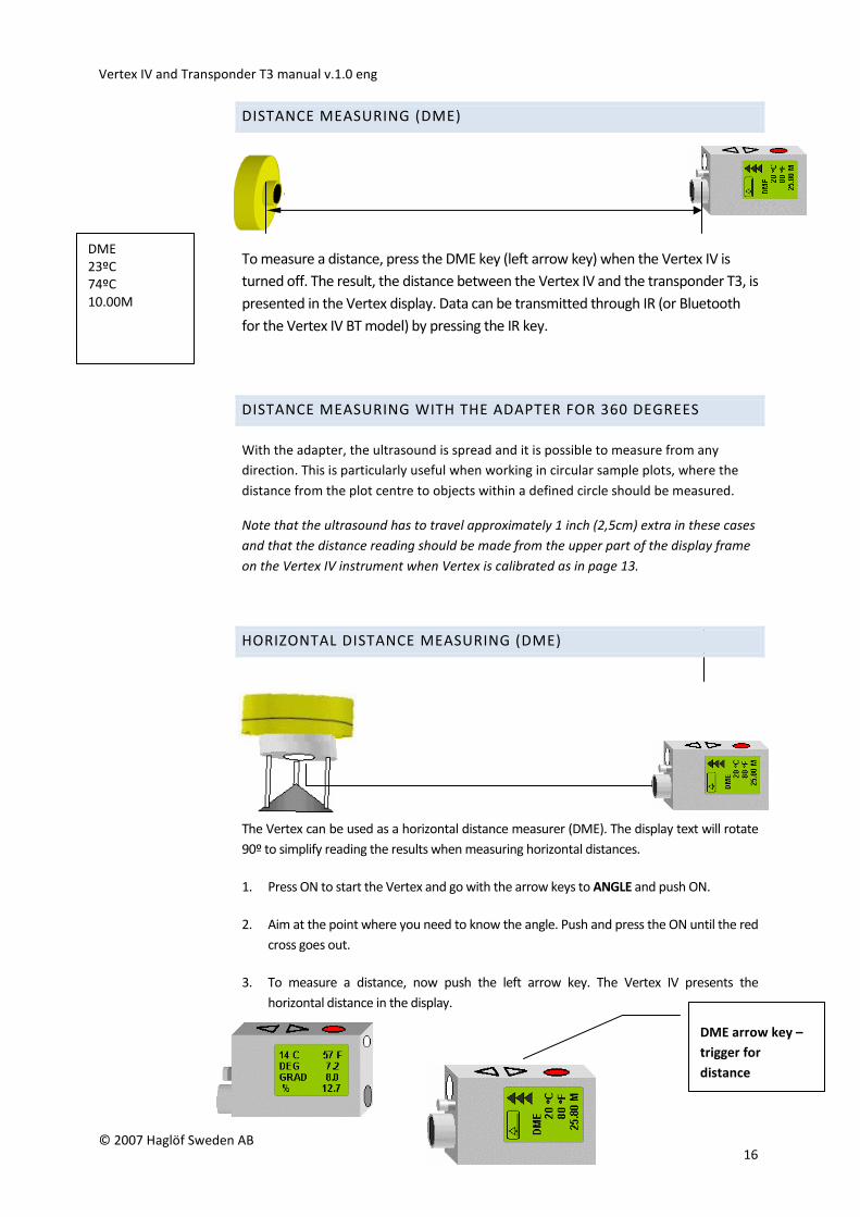
DISTANCE MEASURING (DME)
To measure a distance, press the DME key (left arrow key) when the Vertex IV is
turned off. The result, the distance between the Vertex IV and the transponder T3, is
presented in the Vertex display. Data can be transmitted through IR (or Bluetooth
for the Vertex IV BT model) by pressing the IR key.
DISTANCE MEASURING WITH THE ADAPTER FOR 360 DEGREES
With the adapter, the ultrasound is spread and it is possible to measure from any
direction. This is particularly useful when working in circular sample plots, where the
distance from the plot centre to objects within a defined circle should be measured.
Note that the ultrasound has to travel approximately 1 inch (2,5cm) extra in these cases
and that the distance reading should be made from the upper part of the display frame
on the Vertex IV instrument when Vertex is calibrated as in page 13.
HORIZONTAL DISTANCE MEASURING (DME)
The Vertex can be used as a horizontal distance measurer (DME). The display text will rotate
90º to simplify reading the results when measuring horizontal distances.
1. Press ON to start the Vertex and go with the arrow keys to ANGLE and push ON.
2. Aim at the point where you need to know the angle. Push and press the ON until the red
cross goes out.
3. To measure a distance, now push the left arrow key. The Vertex IV presents the
horizontal distance in the display.
DME
23ºC
74ºC
10.00M
DME arrow key –
trigger for
distance
measuring
Vertex IV and Transponder T3 manual v.1.0 eng
© 2007 Haglöf Sweden AB 17
BAF – SMALLEST DIAMETER
Working in dense forest with relaskopes or prism can sometimes offer
difficulties and accurate diameter estimation hard to make.
When using a relaskopic method to measure, an in-built BAF function can be
used for the Vertex IV instrument to control the minimum diameter for trees.
The function is useful when some trees in an area are covered by other, making
the decision whether to include the tree or to exclude it from the area difficult.
By simply measuring the distance between the tree and the plot centre, the
Vertex IV can calculate the minimum diameter the tree should have in order to
be included into the counting.
Basal Area Factors: 0.5, 1, 2, 3, 4, 5, 6, 7, 8, 9 (m2/ha)
or: 5, 10, 15, 20, 25, 30, 35, 40, 45, 50 (ft2/acre)
BAF factors are changed and set in the SETUP menu.
DIAMETERS IN LEANING TERRAIN
The Vertex IV can compensate the calculated minimum diameter also when the
terrain is leaning. Measure the angle from the tree to the plot centre. Activate
the distance measuring function by pressing the DME key (left arrow key).
The horizontal distance and the calculated minimum diameter is presented in
the display.
DME
23ºC
74ºC
23.5
15.54M
Vertex IV and Transponder T3 manual v.1.0 eng
© 2007 Haglöf Sweden AB 18
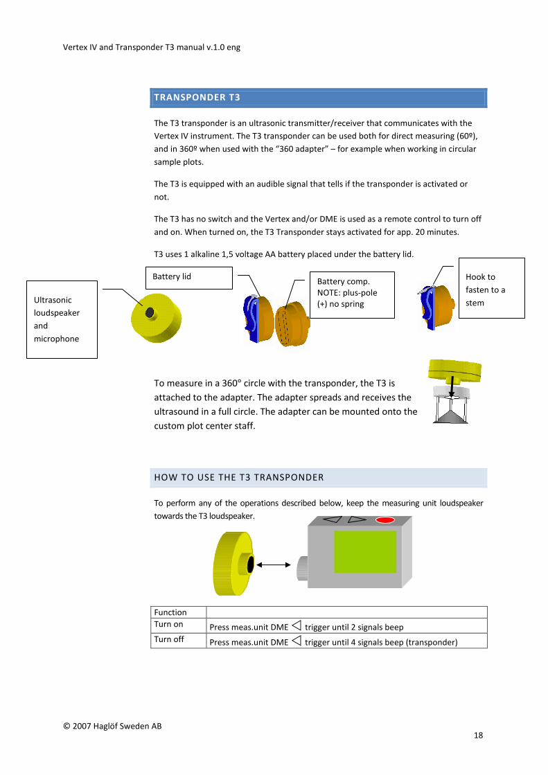
TRANSPONDER T3
The T3 transponder is an ultrasonic transmitter/receiver that communicates with the
Vertex IV instrument. The T3 transponder can be used both for direct measuring (60º),
and in 360º when used with the “360 adapter” – for example when working in circular
sample plots.
The T3 is equipped with an audible signal that tells if the transponder is activated or
not.
The T3 has no switch and the Vertex and/or DME is used as a remote control to turn off
and on. When turned on, the T3 Transponder stays activated for app. 20 minutes.
T3 uses 1 alkaline 1,5 voltage AA battery placed under the battery lid.
To measure in a 360° circle with the transponder, the T3 is
attached to the adapter. The adapter spreads and receives the
ultrasound in a full circle. The adapter can be mounted onto the
custom plot center staff.
HOW TO USE THE T3 TRANSPONDER
To perform any of the operations described below, keep the measuring unit loudspeaker
towards the T3 loudspeaker.
Function
Turn on Press meas.unit DME � trigger until 2 signals beep
Turn off Press meas.unit DME � trigger until 4 signals beep (transponder)
Ultrasonic
loudspeaker
and
microphone
Battery lid Battery comp.
NOTE: plus-pole
(+) no spring
1-2 cm
Hook to
fasten to a
stem
Vertex IV and Transponder T3 manual v.1.0 eng
© 2007 Haglöf Sweden AB 19
BLUETOOTH
Read the following pages if you have the Vertex IV BT model:
The Vertex IV can as an option be equipped with Bluetooth, as the model Vertex IV BT.
The Vertex IV BT can send data wireless to handheld computers or PC, using Bluetooth.
The setup is made with the Vertex IV instrument in slave mode. Certain computer
devices will ask to activate a pin code before making the connection. The pin code
should be activated in the BLUETOOTH menu. The Vertex IV uses default code 12345.
Use this code if pin code has been activated.
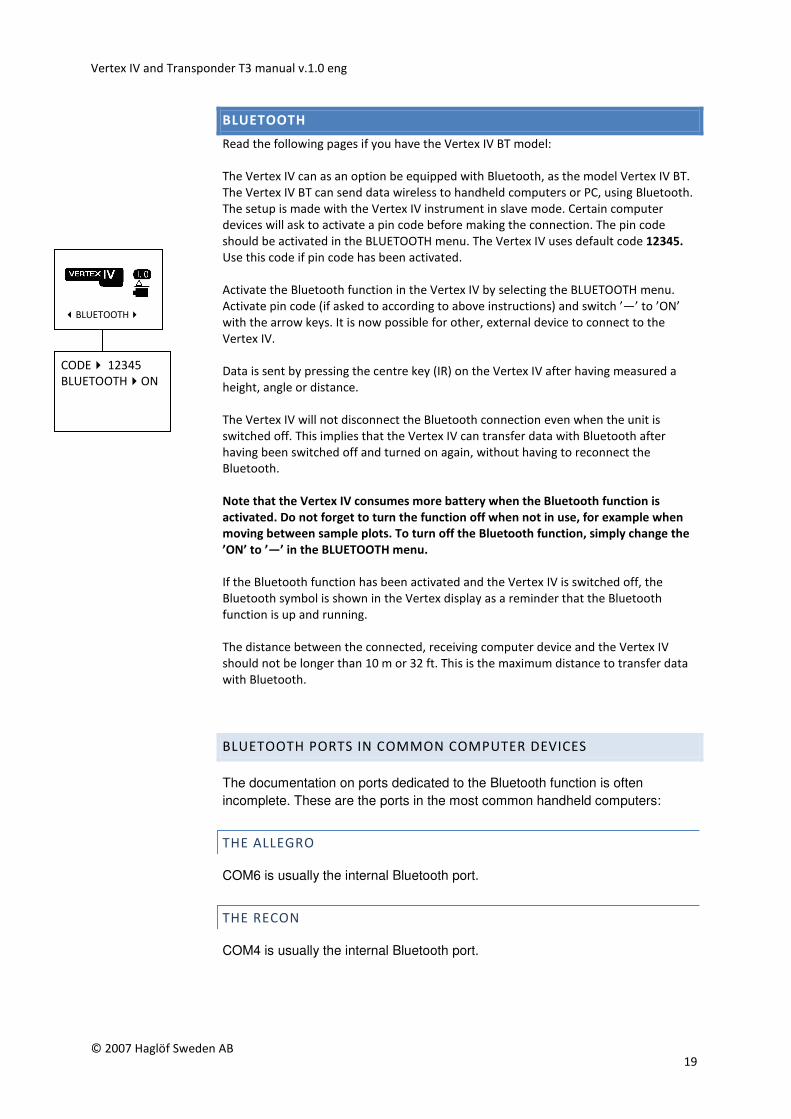
Activate the Bluetooth function in the Vertex IV by selecting the BLUETOOTH menu.
Activate pin code (if asked to according to above instructions) and switch ’—’ to ’ON’
with the arrow keys. It is now possible for other, external device to connect to the
Vertex IV.
Data is sent by pressing the centre key (IR) on the Vertex IV after having measured a
height, angle or distance.
The Vertex IV will not disconnect the Bluetooth connection even when the unit is
switched off. This implies that the Vertex IV can transfer data with Bluetooth after
having been switched off and turned on again, without having to reconnect the
Bluetooth.
Note that the Vertex IV consumes more battery when the Bluetooth function is
activated. Do not forget to turn the function off when not in use, for example when
moving between sample plots. To turn off the Bluetooth function, simply change the
’ON’ to ’—’ in the BLUETOOTH menu.
If the Bluetooth function has been activated and the Vertex IV is switched off, the
Bluetooth symbol is shown in the Vertex display as a reminder that the Bluetooth
function is up and running.
The distance between the connected, receiving computer device and the Vertex IV
should not be longer than 10 m or 32 ft. This is the maximum distance to transfer data
with Bluetooth.
BLUETOOTH PORTS IN COMMON COMPUTER DEVICES
The documentation on ports dedicated to the Bluetooth function is often
incomplete. These are the ports in the most common handheld computers:
THE ALLEGRO
COM6 is usually the internal Bluetooth port.
THE RECON
COM4 is usually the internal Bluetooth port.
�BLUETOOTH�
CODE� 12345 BLUETOOTH�ON
Vertex IV and Transponder T3 manual v.1.0 eng
© 2007 Haglöf Sweden AB 20
DATA FORMAT
Data from the Vertex IV is sent serially as text acc. to below:
The data packet contains a total of 40 signs.
1 0000 [LF][EOL]
2 0000 [LF][EOL]
3 0000 [LF][EOL]
4 0000 [LF][EOL]
5 +000 [LF][EOL] (Negative angle replaces ‘+’with ‘-‘)
LF=Linefeed (ASCII 13)
EOL=End of line (ASCII 10)
HEIGHT MEASURING
Line 1: 1st height (dm alt. feet X 10)
Line 2: 2nd height (dm alt. feet X 10)
Line 3: 3rd height (dm alt. feet X 10)
Line 4: Horizontal distance to the object (dm x 10 alt. ft X10)
Line 5: Angle to the object (centesimal gradients X10 )
DISTANCE MEASURING
Line 1: Distance to transponder (cm alt feet X 10)
Line 2: 0000
Line 3: 0000
Line 4: 0000
Line 5: Angle to the object (centesimal degree X10)
*If the angle (line 5) has a larger or smaller value than zero (0) the distance will be the
calculated horizontal distance.
SIGN FORMAT BLUETOOTH
Transfer speed (Baud Rate) and number of stop bits are automatically set by the
receiver. Number of bits per sign is 8 data bits and no parity.
Vertex IV and Transponder T3 manual v.1.0 eng
© 2007 Haglöf Sweden AB 21
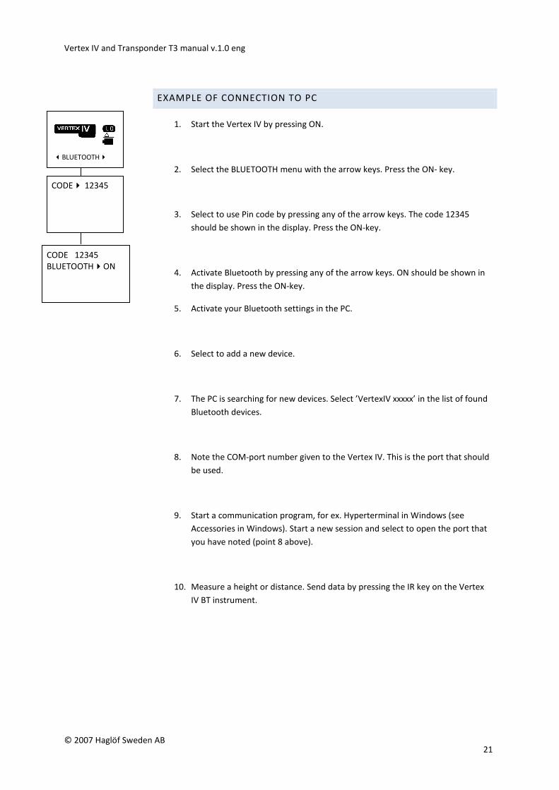
EXAMPLE OF CONNECTION TO PC
1. Start the Vertex IV by pressing ON.
2. Select the BLUETOOTH menu with the arrow keys. Press the ON- key.
3. Select to use Pin code by pressing any of the arrow keys. The code 12345
should be shown in the display. Press the ON-key.
4. Activate Bluetooth by pressing any of the arrow keys. ON should be shown in
the display. Press the ON-key.
5. Activate your Bluetooth settings in the PC.
6. Select to add a new device.
7. The PC is searching for new devices. Select ’VertexIV xxxxx’ in the list of found
Bluetooth devices.
8. Note the COM-port number given to the Vertex IV. This is the port that should
be used.
9. Start a communication program, for ex. Hyperterminal in Windows (see
Accessories in Windows). Start a new session and select to open the port that
you have noted (point 8 above).
10. Measure a height or distance. Send data by pressing the IR key on the Vertex
IV BT instrument.
�BLUETOOTH�
CODE 12345
BLUETOOTH�ON
CODE� 12345
Vertex IV and Transponder T3 manual v.1.0 eng
© 2007 Haglöf Sweden AB 22
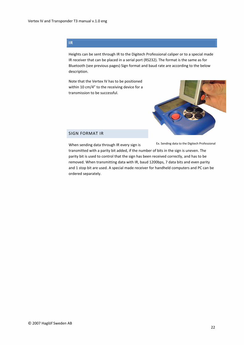
Ex. Sending data to the Digitech Professional
caliper
IR
Heights can be sent through IR to the Digitech Professional caliper or to a special made
IR receiver that can be placed in a serial port (RS232). The format is the same as for
Bluetooth (see previous pages) Sign format and baud rate are according to the below
description.
Note that the Vertex IV has to be positioned
within 10 cm/4” to the receiving device for a
transmission to be successful.
SIGN FORMAT IR
When sending data through IR every sign is
transmitted with a parity bit added, if the number of bits in the sign is uneven. The
parity bit is used to control that the sign has been received correctly, and has to be
removed. When transmitting data with IR, baud 1200bps, 7 data bits and even parity
and 1 stop bit are used. A special made receiver for handheld computers and PC can be
ordered separately.
Vertex IV and Transponder T3 manual v.1.0 eng
© 2007 Haglöf Sweden AB 23
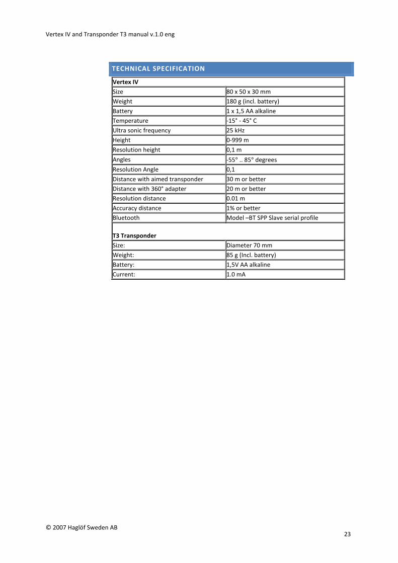
TECHNICAL SPECIFICATION
Vertex IV
Size 80 x 50 x 30 mm
Weight 180 g (incl. battery)
Battery 1 x 1,5 AA alkaline
Temperature -15° - 45° C
Ultra sonic frequency 25 kHz
Height 0-999 m
Resolution height 0,1 m
Angles -55° .. 85° degrees
Resolution Angle 0,1
Distance with aimed transponder 30 m or better
Distance with 360° adapter 20 m or better
Resolution distance 0.01 m
Accuracy distance 1% or better
Bluetooth Model –BT SPP Slave serial profile
T3 Transponder
Size: Diameter 70 mm
Weight: 85 g (Incl. battery)
Battery: 1,5V AA alkaline
Current: 1.0 mA
Vertex IV and Transponder T3 manual v.1.0 eng
© 2007 Haglöf Sweden AB 24
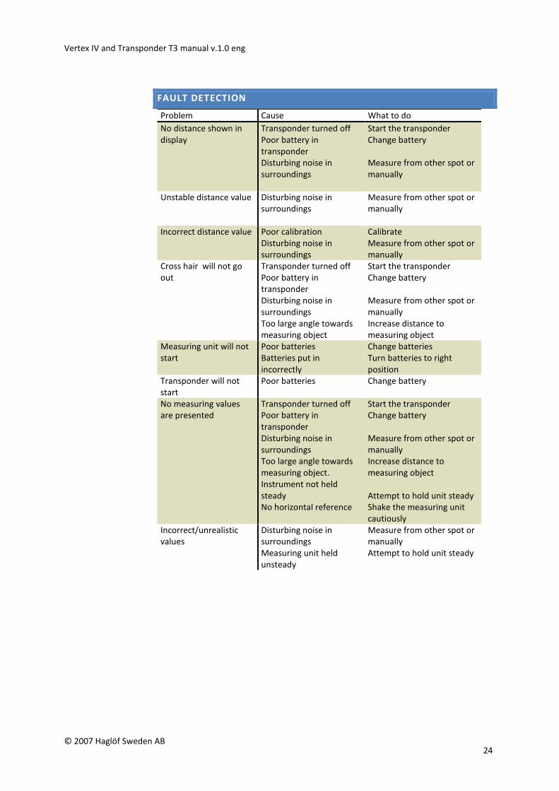
FAULT DETECTION
Problem Cause What to do
No distance shown in
display
Transponder turned off
Poor battery in
transponder
Disturbing noise in
surroundings
Start the transponder
Change battery
Measure from other spot or
manually
Unstable distance value Disturbing noise in
surroundings
Measure from other spot or
manually
Incorrect distance value Poor calibration
Disturbing noise in
surroundings
Calibrate
Measure from other spot or
manually
Cross hair will not go
out
Transponder turned off
Poor battery in
transponder
Disturbing noise in
surroundings
Too large angle towards
measuring object
Start the transponder
Change battery
Measure from other spot or
manually
Increase distance to
measuring object
Measuring unit will not
start
Poor batteries
Batteries put in
incorrectly
Change batteries
Turn batteries to right
position
Transponder will not
start
Poor batteries Change battery
No measuring values
are presented
Transponder turned off
Poor battery in
transponder
Disturbing noise in
surroundings
Too large angle towards
measuring object.
Instrument not held
steady
No horizontal reference
Start the transponder
Change battery
Measure from other spot or
manually
Increase distance to
measuring object
Attempt to hold unit steady
Shake the measuring unit
cautiously
Incorrect/unrealistic
values
Disturbing noise in
surroundings
Measuring unit held
unsteady
Measure from other spot or
manually
Attempt to hold unit steady
Vertex IV and Transponder T3 manual v.1.0 eng
© 2007 Haglöf Sweden AB 25
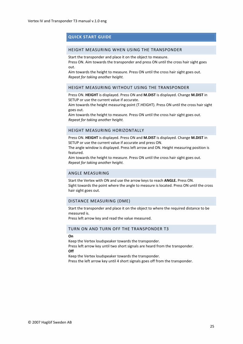
QUICK START GUIDE
HEIGHT MEASURING WHEN USING THE TRANSPONDER
Start the transponder and place it on the object to measure.
Press ON. Aim towards the transponder and press ON until the cross hair sight goes
out.
Aim towards the height to measure. Press ON until the cross hair sight goes out.
Repeat for taking another height.
HEIGHT MEASURING WITHOUT USING THE TRANSPONDER
Press ON. HEIGHT is displayed. Press ON and M.DIST is displayed. Change M.DIST in
SETUP or use the current value if accurate.
Aim towards the height measuring point (T.HEIGHT). Press ON until the cross hair sight
goes out.
Aim towards the height to measure. Press ON until the cross hair sight goes out.
Repeat for taking another height.
HEIGHT MEASURING HORIZONTALLY
Press ON. HEIGHT is displayed. Press ON and M.DIST is displayed. Change M.DIST in
SETUP or use the current value if accurate and press ON.
The angle window is displayed. Press left arrow and ON. Height measuring position is
featured.
Aim towards the height to measure. Press ON until the cross hair sight goes out.
Repeat for taking another height.
ANGLE MEASURING
Start the Vertex with ON and use the arrow keys to reach ANGLE. Press ON.
Sight towards the point where the angle to measure is located. Press ON until the cross
hair sight goes out.
DISTANCE MEASURING (DME)
Start the transponder and place it on the object to where the required distance to be
measured is.
Press left arrow key and read the value measured.
TURN ON AND TURN OFF THE TRANSPONDER T3
On
Keep the Vertex loudspeaker towards the transponder.
Press left arrow key until two short signals are heard from the transponder.
Off
Keep the Vertex loudspeaker towards the transponder.
Press the left arrow key until 4 short signals goes off from the transponder.
Vertex IV and Transponder T3 manual v.1.0 eng
© 2007 Haglöf Sweden AB 26
DECLARATION OF CONFORMITY
According to the EMC Directive with amendment 89/336/EEG & the Low
Voltage Directive 73/23/EEG and 93/68/EEG including amendments by
the CE Marking Directive 93/68/EEG
Type of equipment Distance and angle meter
Brand name or trade mark Vertex
Manufacturer’s name, address, telephone & fax no
Haglöf Sweden AB, Klockargatan 8, SE-882 21 Långsele, Sweden
Tel: +46 620-25585, Fax: +46 620-20581, [email protected];
www.haglofsweden.com
The following standards and/or technical specifications, which comply
with good engineering practice in safety matters in force within the EEA,
have been applied:
Test report/ technical construction file/ normative document
Ref.no 99250/Issued by Forestor AB, Standards EN50081-1, EN 55011
Class B, EN50082-2, EN61000-4-2, -3, Level 3
The Vertex was CE marked 1999
As manufacturer established within EEA, we declare under our sole
responsibility that the equipment follows the provisions of the Directives
stated above.
WARRANTY AND SERVICE INFORMATION
Haglöf Sweden AB warrants that this product shall be free from defects
in materials and workmanship, under normal intended use, for a period
of 12 months after date of shipment. The warranty excludes the
batteries, the accessories and any written materials. The warranty does
not apply if the product has been improperly installed, improperly
calibrated or operated in a manner not in accordance with the user’s
guide. Warranty is also automatically expired if the product has been
opposed to external force and warranty is not applicable for cosmetic
defects. The one-year limited warranty time covers obvious fabrication
defects. Defects in the electronic components that are impossible for the
manufacturer to detect prior to assembling and shipping of the product
may occur. Haglöf Sweden AB can in no case be responsible for problems
of this nature and has no liability for any loss of business, profits, savings,
consequential damages or other damages resulting from use of the
products described. Signs of misuse, cosmetic damage, accidents or
equal automatically withdraw the warranty. The warranty is valid in the
country where your Haglöf product has been purchased. A product
covered by warranty will be object to exchange, service, and repair or
according to special agreement between seller and buyer, within the
frames of the limited warranty. Haglöf Sweden reserves the right to
determine which option will be most suitable for each separate case
after having examined and evaluated the product.
Vertex IV and Transponder T3 manual v.1.0 eng
© 2007 Haglöf Sweden AB 27
IMPORTANT ISSUES:
• For a valid warranty, a copy of invoice or dated receipt of your
purchase must be presented. The serial number of the returned
product has to be clearly stated upon return. Go to
http://www.haglofsweden.com/PDF/HaglofRMA.pdf for return
form/turn to your supplier for assistance.
• The return freight to us is on buyer’s expense. After warranty repair
or exchange, the return freight to you is on our expense. If warranty
has expired or is null and void, all freights are on buyer’s expense.
• If no original invoice can be presented upon shipment, or if two years
or more have passed from date of purchase, a customs fee will be
added by the applicable customs authorities and possibly in receiving
country as well. These fees are on buyers account.
• We perform repair and service of products where warranty has
expired when possible. Cost estimation will be sent to you after
evaluating the returned product for cost approval. Please also see
above paragraph on customs fees.
• Please do not hesitate to contact us or any Haglöf Sweden AB
representative for questions or comments!
Any signs of misuse or negligence automatically withdraw our warranty
commitments
SOFTWARE
© Copyrights of Haglöf Sweden AB Software belong to Haglöf Sweden AB. Unauthorized duplication is
prohibited. Haglöf Sweden AB is registered trademark and VERTEX is a recognized trademark of Haglöf
Sweden AB. Production is made in Sweden.
Haglöf Sweden and its suppliers cannot warrant the performance or results when using the firmware, software
or hardware, nor the documentation. No warranties or conditions are made; neither expressed nor implied, of
merchantability, suitability or special fitness for any particular purpose. If software problems appear, please
contact your programmer for support. Haglöf Sweden takes no responsibility for loss of income, time, or
problems and delays due to problems in soft- or hardware of products. *Copyrights of all software &
firmware made by Haglöf Sweden belong to Haglöf Sweden* Any lists and/or information of software
for any Haglöf Sweden AB products should be considered as brief descriptions and not as a complete guide
to what may and may not be available. For further details, please see ORGALIME SW01, General Conditions
for Computer Software, and Supplement to ORGALIME S 2000 or ORGALIME SE 94.