Embed Size (px)
Citation preview
User’sManual VC200
Mobile Phone TesterPlease Read before Use
IM 733015-03E1st Edition
�IM 7330�5-03E
Thank you for purchasing the VC200 Mobile Phone Tester.This user’s manual contains useful information about the instrument’s functions and operating procedures and lists the handling precautions of the VC200. To ensure correct use, please read this manual thoroughly before beginning operation. Keep this manual in a safe place for quick reference in the event a question arises.
Revisions1st Edition: December 2007
1st Edition : December 2007 (YK)All Rights Reserved, Copyright © 2007 Yokogawa Electric Corporation
� IM 733015-03E
Checking the Contents of the Package
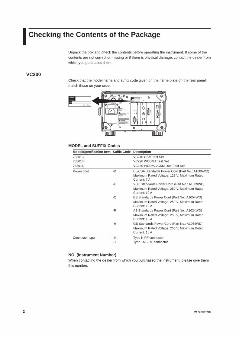
Unpack the box and check the contents before operating the instrument. If some of the contents are not correct or missing or if there is physical damage, contact the dealer from which you purchased them.
VC�00Check that the model name and suffix code given on the name plate on the rear panel match those on your order.
RF IN/OUT
INPUT MAX=4WZin/out=50
1-5Vp-pZin=1k
100-120V/200-240V AC150VA MAX50/60Hz
REF IN
CO
NSO
LE
UE
POW
ER
CLO
CK
OU
TTI
MIN
G O
UT
US
BS
EL
IAL
(RS
-232
)
VID
EO
OU
T(V
GA
)E
TH
ER
NE
T(1
0/10
0BA
SE
-T)
CAUTIONHard disk drive installed.To prevent damage do not applyvibration or shock to the instrument when the power is ON.
MODEL
NO.
SUFFIX
Made in Japan
MODEL
NO.
SUFFIX
Made in Japan
WARNINGDo not operate without reading safety precaution inuser s manual.
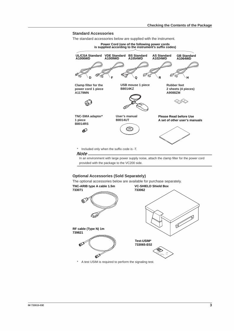
MODEL and SUFFIX CodesModel/Specification Item Suffix Code Description733013 VC210 GSM Test Set733014 VC220 WCDMA Test Set733015 VC230 WCDMA/GSM Dual Test Set
Power cord -D UL/CSA Standards Power Cord (Part No.: A1006WD)Maximum Rated Voltage: 125 V, Maximum Rated Current: 7 A
-F VDE Standards Power Cord (Part No.: A1009WD) Maximum Rated Voltage: 250 V, Maximum Rated Current: 10 A
-Q BS Standards Power Cord (Part No.: A1054WD) Maximum Rated Voltage: 250 V, Maximum Rated Current: 10 A
-R AS Standards Power Cord (Part No.: A1024WD) Maximum Rated Voltage: 250 V, Maximum Rated Current: 10 A
-H GB Standards Power Cord (Part No.: A1064WD) Maximum Rated Voltage: 250 V, Maximum Rated Current: 10 A
Connector type -N Type N RF connector -T Type TNC RF connector
NO. (Instrument Number)When contacting the dealer from which you purchased the instrument, please give them this number.
3IM 7330�5-03E
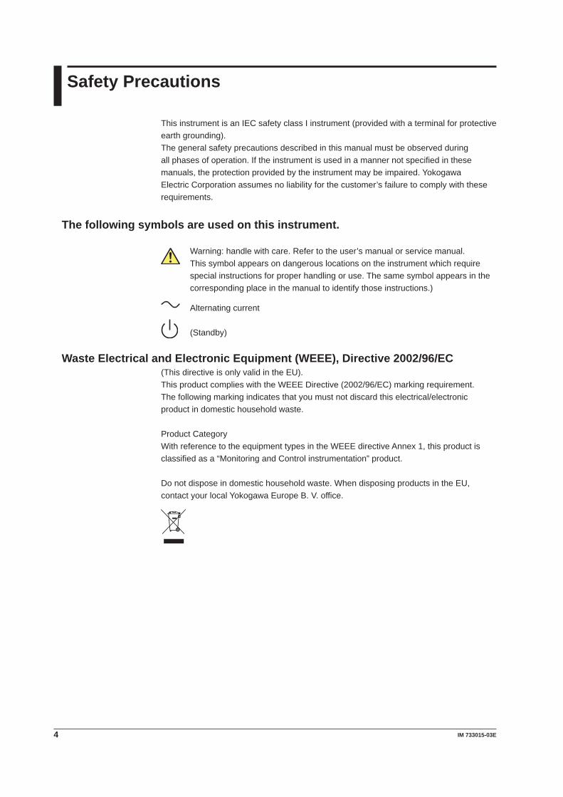
Standard AccessoriesThe standard accessories below are supplied with the instrument.
User’s manualB8014UT
Rubber feet2 sheets (4 pieces)A9088ZM
Clamp filter for the power cord 1 pieceA1179MN
TNC-SMA adapter* 1 pieceB8014RS
USB mouse 1 pieceB8014KZ
Please Read before UseA set of other user’s manuals
UL/CSA StandardA1006WD
VDE StandardA1009WD
BS StandardA1054WD
AS StandardA1024WD
D F Q R
Power Cord (one of the following power cordsis supplied according to the instrument’s suffix codes)
GB StandardA1064WD
H
* Included only when the suffix code is -T.Note
In an environment with large power supply noise, attach the clamp filter for the power cord provided with the package to the VC200 side.
Optional Accessories (Sold Separately)The optional accessories below are available for purchase separately.
TNC-ARIB type A cable 1.5m733071
VC-SHIELD Shield Box733062
Test-USIM*733065-E02
RF cable (Type N) 1m739821
* A test USIM is required to perform the signaling test.
Checking the Contents of the Package
� IM 7330�5-03E
Safety Precautions
This instrument is an IEC safety class I instrument (provided with a terminal for protective earth grounding).The general safety precautions described in this manual must be observed during all phases of operation. If the instrument is used in a manner not specified in these manuals, the protection provided by the instrument may be impaired. Yokogawa Electric Corporation assumes no liability for the customer’s failure to comply with these requirements.
The following symbols are used on this instrument.
Warning: handle with care. Refer to the user’s manual or service manual. This symbol appears on dangerous locations on the instrument which require special instructions for proper handling or use. The same symbol appears in the corresponding place in the manual to identify those instructions.)
Alternating current
(Standby)
Waste Electrical and Electronic Equipment (WEEE), Directive 2002/96/EC(This directive is only valid in the EU).This product complies with the WEEE Directive (2002/96/EC) marking requirement.The following marking indicates that you must not discard this electrical/electronic product in domestic household waste.
Product CategoryWith reference to the equipment types in the WEEE directive Annex 1, this product is classified as a “Monitoring and Control instrumentation” product.
Do not dispose in domestic household waste. When disposing products in the EU, contact your local Yokogawa Europe B. V. office.
5IM 7330�5-03E
Make sure to comply with the precautions below. Not complying might result in injury or death.
WARNINGUse the Correct Power SupplyBefore connecting the power cord, ensure that the source voltage matches the rated supply voltage of the instrument and that it is within the maximum rated voltage of the provided power cord.
Use the Correct Power Cord and PlugTo prevent the possibility of electric shock or fire, be sure to use the power cord supplied by YOKOGAWA. The main power plug must be plugged into an outlet with a protective earth terminal. Do not disable this protection by using an extension cord without protective earth grounding.
Connect the Protective Grounding TerminalBe sure to connect the protective earth to prevent electric shock before turning ON the power. The power cord that comes with the instrument is a three-prong type power cord. Connect the power cord to a properly grounded three-prong outlet.
Do Not Impair the Protective GroundingNever cut off the internal or external protective earth wire or disconnect the wiring of the protective earth terminal. Doing so poses a potential shock hazard.
Do Not Operate with Defective Protective Grounding or FuseDo not operate the instrument if the protective earth or fuse might be defective. Also, make sure to check them before operation.
Do Not Operate in an Explosive AtmosphereDo not operate the instrument in the presence of flammable liquids or vapors. Operation in such an environment constitutes a safety hazard.
Do Not Remove CoversThe cover should be removed by YOKOGAWA’s qualified personnel only. Opening the cover is dangerous, because some areas inside the instrument have high voltages.
Ground the Instrument before Making External ConnectionsSecurely connect the protective grounding before connecting to the item under measurement or to an external control unit. If you are going to touch the circuit, make sure to turn OFF the circuit and check that no voltage is present.
Be sure to comply with the precautions below. There are limitations to the operating environment.
CAUTIONThis product is a Class A (for industrial environment) product. Operation of this product in a residential area may cause radio interference in which case the user is required to correct the interference.
Safety Precautions
6 IM 7330�5-03E
Handling Precautions
Read the Safety PrecautionsSafety PrecautionsWhen using the VC200 for the first time, make sure to read “Safety Precautions” on pages 4 and 5.
Do Not Remove the CaseDo not remove the case from the instrument. Some sections inside the instrument have high voltages that are extremely dangerous. For internal inspection and adjustment, contact your nearest YOKOGAWA dealer.
Unplug If Abnormal Behavior OccursStop using the instrument if there are any symptoms of trouble such as strange odors or smoke coming from the instrument. If these symptoms occur, immediately turn OFF the power and unplug the power cord. If these symptoms occur, contact your nearest YOKOGAWA dealer.
If the Cooling Fan StopsIf error code 1027 appears on the display, the cooling fan is stopped. Immediately turn OFF the power switch. If terror code 1027 appears when you turn ON the power switch again, it is probably a malfunction. Contact your nearest YOKOGAWA dealer.
Do Not Damage the Power CordNothing should be placed on top of the power cord. The power cord should also be kept away from any heat sources. When unplugging the power cord from the outlet, never pull by the cord itself. Always hold and pull by the plug. If the power cord is damaged, check the part number indicated on page 2 and purchase a replacement.
General Handling PrecautionsDo Not Place Objects on Top of the InstrumentNever place objects containing water on top of the instrument, otherwise a breakdown may occur.
Do Not Apply Shock or VibrationDo not apply shock or vibration. If you do, the VC200 may malfunction. Exercise extra caution because the internal hard disk is sensitive to vibration and shock. In addition, applying shock to the input/output terminal or the connected cable can cause electrical noise to enter or output from the instrument.
Do Not Damage the LCDThe LCD is very vulnerable to scratches. Be careful not to damage the surface with sharp objects. Also, do not apply vibration or shock to it.
Keep Electrically Charged Objects Away from the InstrumentKeep electrically charged objects away from the input connectors. They may damage the internal circuitry.
Unplug during Extended Non-UseTurn OFF the power switch and remove the power cord from the outlet.
7IM 7330�5-03E
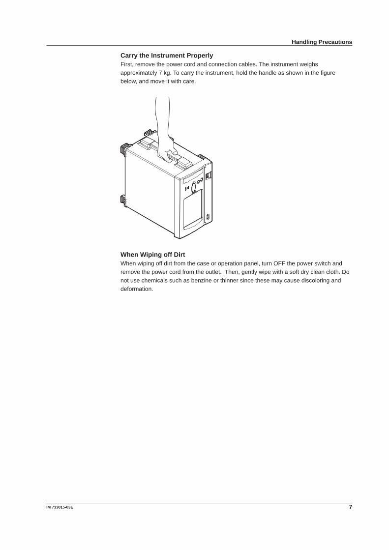
Carry the Instrument ProperlyFirst, remove the power cord and connection cables. The instrument weighs approximately 7 kg. To carry the instrument, hold the handle as shown in the figure below, and move it with care.
When Wiping off DirtWhen wiping off dirt from the case or operation panel, turn OFF the power switch and remove the power cord from the outlet. Then, gently wipe with a soft dry clean cloth. Do not use chemicals such as benzine or thinner since these may cause discoloring and deformation.
Handling Precautions
� IM 7330�5-03E
Installation
Installation Position
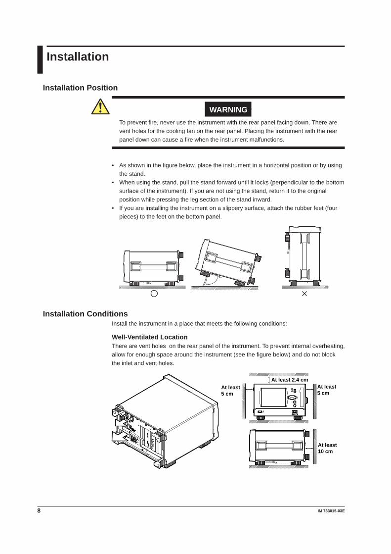
WARNINGTo prevent fire, never use the instrument with the rear panel facing down. There are vent holes for the cooling fan on the rear panel. Placing the instrument with the rear panel down can cause a fire when the instrument malfunctions.
• As shown in the figure below, place the instrument in a horizontal position or by using the stand.
• When using the stand, pull the stand forward until it locks (perpendicular to the bottom surface of the instrument). If you are not using the stand, return it to the original position while pressing the leg section of the stand inward.
• If you are installing the instrument on a slippery surface, attach the rubber feet (four pieces) to the feet on the bottom panel.
Installation ConditionsInstall the instrument in a place that meets the following conditions:
Well-Ventilated LocationThere are vent holes on the rear panel of the instrument. To prevent internal overheating, allow for enough space around the instrument (see the figure below) and do not block the inlet and vent holes.
At least 10 cm
At least 5 cm
At least 2.4 cmAt least 5 cm
POWER
HARD DISK
STOP
DISPLAY OFF
USB
START
9IM 7330�5-03E
Ambient Temperature and HumidityUse the instrument in the following environment:• Ambient temperature: 5 to 35°C However, in order to obtain highly accurate measurements, operate the instrument in
the 23 ± 5 °C temperature range.• Ambient humidity: 20 to 80%RH No condensation should be present. However, in order to obtain highly accurate
measurements, operate the instrument in the 50 ± 10% RH range.
Note• Condensation may occur if the instrument is moved to another place where the ambient
temperature is higher, or if the temperature changes rapidly. If this happens, let the VC200 adjust to the new environment for at least one hour before using it.
Do not install the instrument in the following places.• In direct sunlight or near heat sources.• Where an excessive amount of soot, steam, dust, or corrosive gas is present.• Near strong magnetic field sources.• Near high voltage equipment or power lines.• Where the level of mechanical vibration is high.• On an unstable surface.
Storage Location• We strongly recommend you store the VC200 in an environment with a temperature
between 5 and 40°C and a relative humidity between 20 to 80%RH.• When storing the VC200, avoid the following types of locations:
• In direct sunlight.• Where the temperature is 60°C or higher.• A place with a relative humidity of 80% or more.• Near heat sources• Where the level of mechanical vibration is high.• Where corrosive or explosive gas is present.• Where an excessive amount of soot, dust, salt, and iron are present.• Where water, oil, or chemicals may splash.
Installation
�0 IM 7330�5-03E
Recommended Replacement Parts
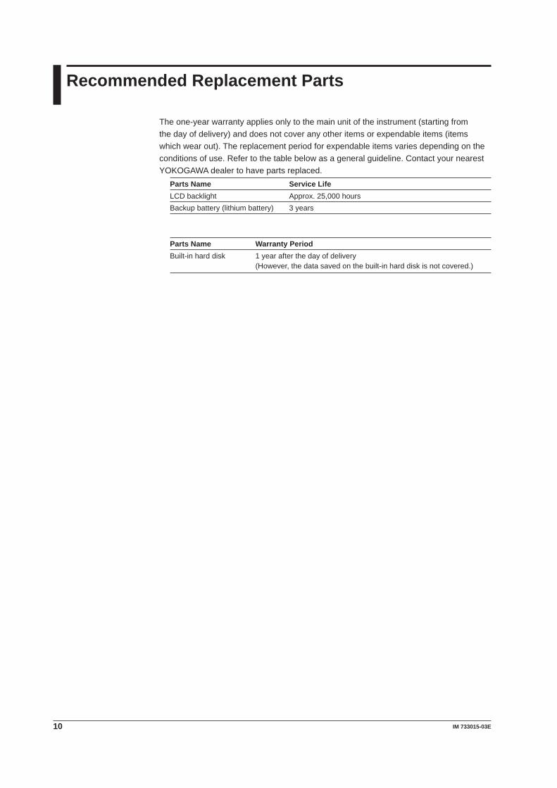
The one-year warranty applies only to the main unit of the instrument (starting from the day of delivery) and does not cover any other items or expendable items (items which wear out). The replacement period for expendable items varies depending on the conditions of use. Refer to the table below as a general guideline. Contact your nearest YOKOGAWA dealer to have parts replaced.
Parts Name Service LifeLCD backlight Approx. 25,000 hoursBackup battery (lithium battery) 3 years
Parts Name Warranty PeriodBuilt-in hard disk 1 year after the day of delivery (However, the data saved on the built-in hard disk is not covered.)
��IM 7330�5-03E
General Specifications
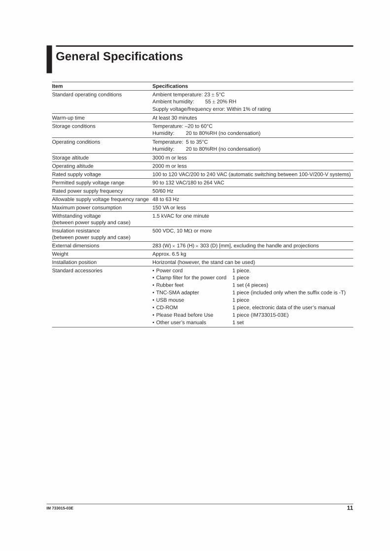
Item SpecificationsStandard operating conditions Ambient temperature: 23 ± 5°C
Ambient humidity: 55 ± 20% RHSupply voltage/frequency error: Within 1% of rating
Warm-up time At least 30 minutesStorage conditions Temperature: –20 to 60°C
Humidity: 20 to 80%RH (no condensation)
Operating conditions Temperature: 5 to 35°CHumidity: 20 to 80%RH (no condensation)
Storage altitude 3000 m or lessOperating altitude 2000 m or lessRated supply voltage 100 to 120 VAC/200 to 240 VAC (automatic switching between 100-V/200-V systems)Permitted supply voltage range 90 to 132 VAC/180 to 264 VACRated power supply frequency 50/60 HzAllowable supply voltage frequency range 48 to 63 HzMaximum power consumption 150 VA or lessWithstanding voltage 1.5 kVAC for one minute (between power supply and case)Insulation resistance 500 VDC, 10 MW or more (between power supply and case)External dimensions 283 (W) × 176 (H) × 303 (D) [mm], excluding the handle and projectionsWeight Approx. 6.5 kgInstallation position Horizontal (however, the stand can be used)Standard accessories • Power cord 1 piece.
• Clamp filter for the power cord 1 piece• Rubber feet 1 set (4 pieces)• TNC-SMA adapter 1 piece (included only when the suffix code is -T)• USB mouse 1 piece • CD-ROM 1 piece, electronic data of the user’s manual• Please Read before Use 1 piece (IM733015-03E)• Other user’s manuals 1 set
�2 IM 7330�5-03E
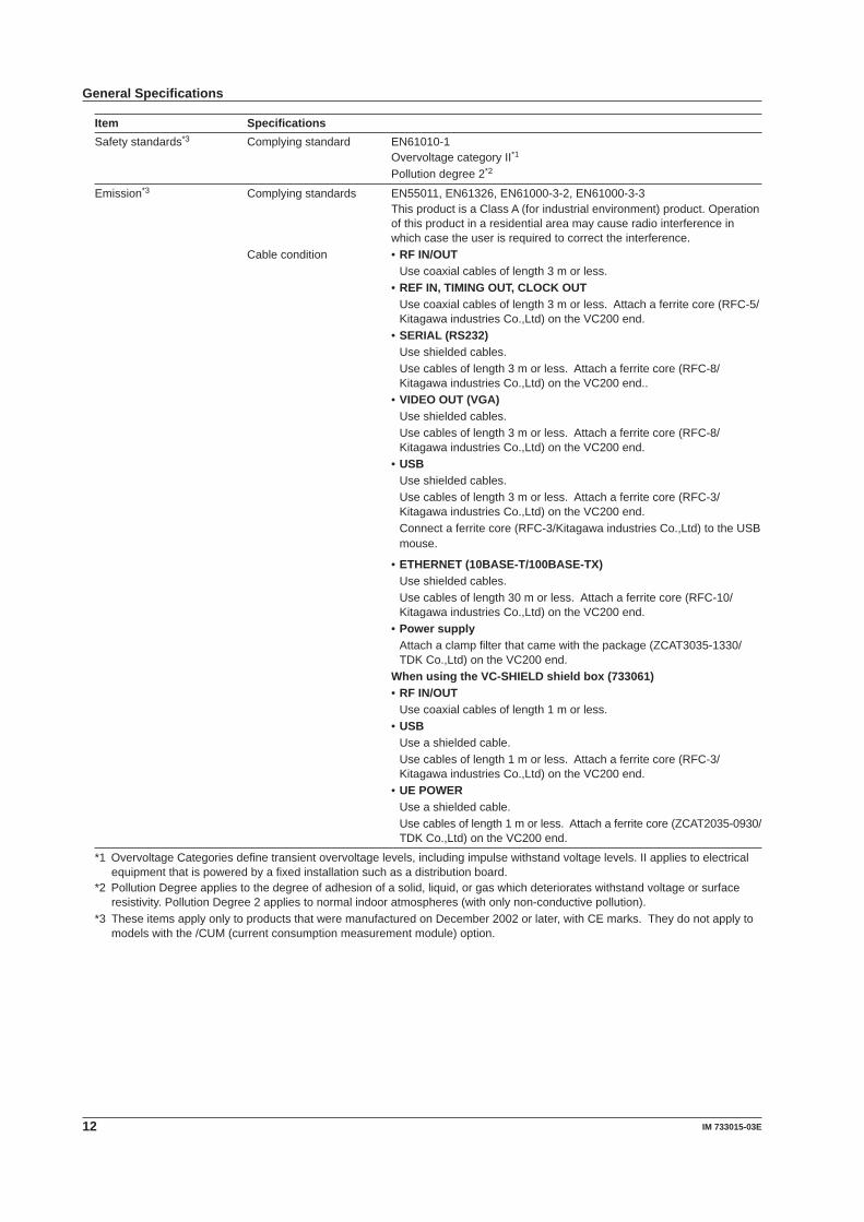
Item SpecificationsSafety standards*3 Complying standard EN61010-1
Overvoltage category II*1
Pollution degree 2*2
Emission*3 Complying standards EN55011, EN61326, EN61000-3-2, EN61000-3-3This product is a Class A (for industrial environment) product. Operation of this product in a residential area may cause radio interference in which case the user is required to correct the interference.
Cable condition • RF IN/OUTUse coaxial cables of length 3 m or less.
• REF IN, TIMING OUT, CLOCK OUTUse coaxial cables of length 3 m or less. Attach a ferrite core (RFC-5/Kitagawa industries Co.,Ltd) on the VC200 end.
• SERIAL (RS232)Use shielded cables.Use cables of length 3 m or less. Attach a ferrite core (RFC-8/Kitagawa industries Co.,Ltd) on the VC200 end..
• VIDEO OUT (VGA)Use shielded cables.Use cables of length 3 m or less. Attach a ferrite core (RFC-8/Kitagawa industries Co.,Ltd) on the VC200 end.
• USBUse shielded cables.Use cables of length 3 m or less. Attach a ferrite core (RFC-3/Kitagawa industries Co.,Ltd) on the VC200 end.Connect a ferrite core (RFC-3/Kitagawa industries Co.,Ltd) to the USB mouse.
• ETHERNET (�0BASE-T/�00BASE-TX)Use shielded cables.Use cables of length 30 m or less. Attach a ferrite core (RFC-10/Kitagawa industries Co.,Ltd) on the VC200 end.
• Power supplyAttach a clamp filter that came with the package (ZCAT3035-1330/TDK Co.,Ltd) on the VC200 end.
When using the VC-SHIELD shield box (73306�)• RF IN/OUT
Use coaxial cables of length 1 m or less.• USB
Use a shielded cable.Use cables of length 1 m or less. Attach a ferrite core (RFC-3/Kitagawa industries Co.,Ltd) on the VC200 end.
• UE POWERUse a shielded cable.Use cables of length 1 m or less. Attach a ferrite core (ZCAT2035-0930/TDK Co.,Ltd) on the VC200 end.
*1 Overvoltage Categories define transient overvoltage levels, including impulse withstand voltage levels. II applies to electrical equipment that is powered by a fixed installation such as a distribution board.
*2 Pollution Degree applies to the degree of adhesion of a solid, liquid, or gas which deteriorates withstand voltage or surface resistivity. Pollution Degree 2 applies to normal indoor atmospheres (with only non-conductive pollution).
*3 These items apply only to products that were manufactured on December 2002 or later, with CE marks. They do not apply to models with the /CUM (current consumption measurement module) option.
General Specifications
�3IM 7330�5-03E
Using the CD-ROM
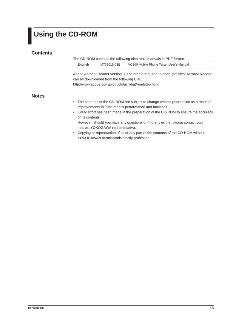
ContentsThe CD-ROM contains the following electronic manuals in PDF format.
English IM733015-01E VC200 Mobile Phone Tester User’s Manual
Adobe Acrobat Reader version 3.0 or later is required to open .pdf files. Acrobat Reader can be downloaded from the following URL.http://www.adobe.com/products/acrobat/readstep.html
Notes• The contents of the CD-ROM are subject to change without prior notice as a result of
improvements in instrument’s performance and functions.• Every effort has been made in the preparation of the CD-ROM to ensure the accuracy
of its contents. However, should you have any questions or find any errors, please contact your
nearest YOKOGAWA representative.• Copying or reproduction of all or any part of the contents of the CD-ROM without
YOKOGAWA’s permissionis strictly prohibited.