Embed Size (px)
Citation preview
vSphere NetworkingUpdate 211 APR 2018VMware vSphere 6.7VMware ESXi 6.7vCenter Server 6.7
You can find the most up-to-date technical documentation on the VMware website at:
https://docs.vmware.com/
If you have comments about this documentation, submit your feedback to
VMware, Inc.3401 Hillview Ave.Palo Alto, CA 94304www.vmware.com
Copyright © 2009-2019 VMware, Inc. All rights reserved. Copyright and trademark information.
vSphere Networking
VMware, Inc. 2
Contents
About vSphere Networking 11
Updated Information 12
1 Introduction to vSphere Networking 13Networking Concepts Overview 13
Network Services in ESXi 15
VMware ESXi Dump Collector Support 15
2 Setting Up Networking with vSphere Standard Switches 17vSphere Standard Switches 17
Create a vSphere Standard Switch 19
Port Group Configuration for Virtual Machines 20
Add a Virtual Machine Port Group 21
Edit a Standard Switch Port Group 22
Remove a Port Group from a vSphere Standard Switch 23
vSphere Standard Switch Properties 23
Change the Size of the MTU on a vSphere Standard Switch 23
Change the Speed of a Physical Adapter 24
Add and Team Physical Adapters in a vSphere Standard Switch 24
View the Topology Diagram of a vSphere Standard Switch 25
3 Setting Up Networking with vSphere Distributed Switches 27vSphere Distributed Switch Architecture 27
Create a vSphere Distributed Switch 31
Upgrade a vSphere Distributed Switch to a Later Version 32
Edit General and Advanced vSphere Distributed Switch Settings 33
Managing Networking on Multiple Hosts on a vSphere Distributed Switch 34
Tasks for Managing Host Networking on a vSphere Distributed Switch 35
Add Hosts to a vSphere Distributed Switch 37
Configure Physical Network Adapters on a vSphere Distributed Switch 38
Migrate VMkernel Adapters to a vSphere Distributed Switch 39
Create a VMkernel Adapter on a vSphere Distributed Switch 40
Migrate Virtual Machine Networking to the vSphere Distributed Switch 42
Use a Host as a Template to Create a Uniform Networking Configuration on a vSphere Distributed Switch 43
Remove Hosts from a vSphere Distributed Switch 45
Managing Networking on Host Proxy Switches 46
VMware, Inc. 3

Migrate Network Adapters on a Host to a vSphere Distributed Switch 46
Migrate a VMkernel Adapter on a Host to a vSphere Standard Switch 47
Assign a Physical NIC of a Host to a vSphere Distributed Switch 48
Remove a Physical NIC from a vSphere Distributed Switch 48
Removing NICs from Active Virtual Machines 48
Distributed Port Groups 49
Add a Distributed Port Group 49
Edit General Distributed Port Group Settings 52
Configure Overriding Networking Policies on Port Level 53
Remove a Distributed Port Group 54
Working with Distributed Ports 54
Monitor the State of Distributed Ports 54
Configure Distributed Port Settings 55
Configuring Virtual Machine Networking on a vSphere Distributed Switch 56
Migrate Virtual Machines to or from a vSphere Distributed Switch 56
Connect an Individual Virtual Machine to a Distributed Port Group 56
Topology Diagrams of a vSphere Distributed Switch in the vSphere Web Client 57
View the Topology of a vSphere Distributed Switch 58
View the Topology of a Host Proxy Switch 59
4 Setting Up VMkernel Networking 60VMkernel Networking Layer 61
View Information About VMkernel Adapters on a Host 63
Create a VMkernel Adapter on a vSphere Standard Switch 64
Create a VMkernel Adapter on a Host Associated with a vSphere Distributed Switch 66
Edit a VMkernel Adapter Configuration 68
Overriding the Default Gateway of a VMkernel Adapter 70
Configure the VMkernel Adapter Gateway by Using esxcli Commands 70
View TCP/IP Stack Configuration on a Host 71
Change the Configuration of a TCP/IP Stack on a Host 72
Create a Custom TCP/IP Stack 72
Remove a VMkernel Adapter 73
5 LACP Support on a vSphere Distributed Switch 74LACP Teaming and Failover Configuration for Distributed Port Groups 76
Configure a Link Aggregation Group to Handle the Traffic for Distributed Port Groups 77
Create a Link Aggregation Group 78
Set a Link Aggregating Group as Standby in the Teaming and Failover Order of Distributed Port Groups 79
Assign Physical NICs to the Ports of the Link Aggregation Group 80
Set the Link Aggregation Group as Active in the Teaming and Failover Order of the Distributed Port Group 80
vSphere Networking
VMware, Inc. 4
Edit a Link Aggregation Group 81
Limitations of the LACP Support on a vSphere Distributed Switch 82
6 Backing Up and Restoring Networking Configurations 83Backing Up and Restoring a vSphere Distributed Switch Configuration 83
Export vSphere Distributed Switch Configurations 83
Import a vSphere Distributed Switch Configuration 84
Restore a vSphere Distributed Switch Configuration 85
Export, Import, and Restore vSphere Distributed Port Group Configurations 85
Export vSphere Distributed Port Group Configurations 85
Import a vSphere Distributed Port Group Configuration 86
Restore a vSphere Distributed Port Group Configuration 87
7 Rollback and Recovery of the Management Network 88vSphere Networking Rollback 88
Disable Network Rollback 89
Disable Network Rollback by Using the vCenter Server Configuration File 90
Resolve Errors in the Management Network Configuration on a vSphere Distributed Switch 90
8 Networking Policies 92Applying Networking Policies on a vSphere Standard or Distributed Switch 93
Configure Overriding Networking Policies on Port Level 94
Teaming and Failover Policy 95
Load Balancing Algorithms Available for Virtual Switches 97
Configure NIC Teaming, Failover, and Load Balancing on a vSphere Standard Switch or Standard Port Group 101
Configure NIC Teaming, Failover, and Load Balancing on a Distributed Port Group or Distributed Port103
VLAN Policy 105
Configure VLAN Tagging on a Distributed Port Group or Distributed Port 106
Configure VLAN Tagging on an Uplink Port Group or Uplink Port 107
Security Policy 107
Configure the Security Policy for a vSphere Standard Switch or Standard Port Group 108
Configure the Security Policy for a Distributed Port Group or Distributed Port 109
Traffic Shaping Policy 110
Configure Traffic Shaping for a vSphere Standard Switch or Standard Port Group 111
Edit the Traffic Shaping Policy on a Distributed Port Group or Distributed Port 112
Resource Allocation Policy 113
Edit the Resource Allocation Policy on a Distributed Port Group 114
Monitoring Policy 114
Enable or Disable NetFlow Monitoring on a Distributed Port Group or Distributed Port 114
Traffic Filtering and Marking Policy 115
vSphere Networking
VMware, Inc. 5
Traffic Filtering and Marking on a Distributed Port Group or Uplink Port Group 116
Traffic Filtering and Marking on a Distributed Port or Uplink Port 123
Qualifying Traffic for Filtering and Marking 131
Manage Policies for Multiple Port Groups on a vSphere Distributed Switch 134
Port Blocking Policies 139
Edit the Port Blocking Policy for a Distributed Port Group 139
Edit the Blocking Policy for a Distributed Port or Uplink Port 139
9 Isolating Network Traffic by Using VLANs 141VLAN Configuration 141
Private VLANs 142
Create a Private VLAN 142
Remove a Primary Private VLAN 143
Remove a Secondary Private VLAN 143
10 Managing Network Resources 145DirectPath I/O 145
Enable Passthrough for a Network Device on a Host 146
Configure a PCI Device on a Virtual Machine 146
Single Root I/O Virtualization (SR-IOV) 147
SR-IOV Support 148
SR-IOV Component Architecture and Interaction 150
vSphere and Virtual Function Interaction 152
DirectPath I/O vs SR-IOV 153
Configure a Virtual Machine to Use SR-IOV 153
Networking Options for the Traffic Related to an SR-IOV Enabled Virtual Machine 156
Using an SR-IOV Physical Adapter to Handle Virtual Machine Traffic 156
Enabling SR-IOV by Using Host Profiles or an ESXCLI Command 157
Virtual Machine That Uses an SR-IOV Virtual Function Fails to Power On Because the Host Is Out of Interrupt Vectors 159
Remote Direct Memory Access for Virtual Machines 160
PVRDMA Support 160
Configure an ESXi Host for PVRDMA 161
Assign a PVRDMA Adapter to a Virtual Machine 162
Network Requirements for RDMA over Converged Ethernet 163
Jumbo Frames 164
Enable Jumbo Frames on a vSphere Distributed Switch 164
Enable Jumbo Frames on a vSphere Standard Switch 164
Enable Jumbo Frames for a VMkernel Adapter 165
Enable Jumbo Frame Support on a Virtual Machine 165
TCP Segmentation Offload 166
Enable or Disable Software TSO in the VMkernel 166
vSphere Networking
VMware, Inc. 6
Determine Whether TSO Is Supported on the Physical Network Adapters on an ESXi Host 167
Enable or Disable TSO on an ESXi Host 167
Determine Whether TSO Is Enabled on an ESXi Host 168
Enable or Disable TSO on a Linux Virtual Machine 168
Enable or Disable TSO on a Windows Virtual Machine 169
Large Receive Offload 169
Enable Hardware LRO for All VMXNET3 Adapters on an ESXi Host 169
Enable or Disable Software LRO for All VMXNET3 Adapters on an ESXi Host 170
Determine Whether LRO Is Enabled for VMXNET3 Adapters on an ESXi Host 170
Change the Size of the LRO Buffer for VMXNET 3 Adapters 171
Enable or Disable LRO for All VMkernel Adapters on an ESXi Host 171
Change the Size of the LRO Buffer for VMkernel Adapters 172
Enable or Disable LRO on a VMXNET3 Adapter on a Linux Virtual Machine 172
Enable or Disable LRO on a VMXNET3 Adapter on a Windows Virtual Machine 172
Enable LRO Globally on a Windows Virtual Machine 173
NetQueue and Networking Performance 174
Enable NetQueue on a Host 174
Disable NetQueue on a Host 174
11 vSphere Network I/O Control 176About vSphere Network I/O Control Version 3 176
Enable Network I/O Control on a vSphere Distributed Switch 177
Bandwidth Allocation for System Traffic 177
Bandwidth Allocation Parameters for System Traffic 178
Example Bandwidth Reservation for System Traffic 179
Configure Bandwidth Allocation for System Traffic 179
Bandwidth Allocation for Virtual Machine Traffic 180
About Allocating Bandwidth for Virtual Machines 181
Bandwidth Allocation Parameters for Virtual Machine Traffic 183
Admission Control for Virtual Machine Bandwidth 183
Create a Network Resource Pool 184
Add a Distributed Port Group to a Network Resource Pool 185
Configure Bandwidth Allocation for a Virtual Machine 186
Configure Bandwidth Allocation on Multiple Virtual Machines 187
Change the Quota of a Network Resource Pool 188
Remove a Distributed Port Group from a Network Resource Pool 189
Delete a Network Resource Pool 189
Move a Physical Adapter Out the Scope of Network I/O Control 189
12 MAC Address Management 191MAC Address Assignment from vCenter Server 191
vSphere Networking
VMware, Inc. 7

VMware OUI Allocation 192
Prefix-Based MAC Address Allocation 192
Range-Based MAC Address Allocation 193
Assigning a MAC Address 193
MAC Address Generation on ESXi Hosts 195
Setting a Static MAC Address to a Virtual Machine 196
VMware OUI in Static MAC Addresses 196
Assign a Static MAC Address by Using the vSphere Web Client 197
Assign a Static MAC Address in the Virtual Machine Configuration File 197
13 Configuring vSphere for IPv6 199vSphere IPv6 Connectivity 199
Deploying vSphere on IPv6 201
Enable IPv6 on a vSphere Installation 201
Enable IPv6 on an Upgraded vSphere Environment 202
Enable or Disable IPv6 Support on a Host 204
Set Up IPv6 on an ESXi Host 204
Setting Up IPv6 on vCenter Server 205
Set Up IPv6 on the vCenter Server Appliance 205
Set Up vCenter Server on Windows with IPv6 206
14 Monitoring Network Connection and Traffic 207Capture Network Packets by Using the PacketCapture Utility 207
Capturing and Tracing Network Packets by Using the pktcap-uw Utility 209
pktcap-uw Command Syntax for Capturing Packets 209
pktcap-uw Command Syntax for Tracing Packets 212
pktcap-uw Options for Output Control 212
pktcap-uw Options for Filtering Packets 213
Capturing Packets by Using the pktcap-uw Utility 214
Trace Packets by Using the pktcap-uw Utility 224
Configure the NetFlow Settings of a vSphere Distributed Switch 225
Working With Port Mirroring 226
Port Mirroring Interoperability 226
Create a Port Mirroring Session 228
View Port Mirroring Session Details 231
Edit Port Mirroring Session Details, Sources, and Destinations 231
vSphere Distributed Switch Health Check 233
Enable or Disable vSphere Distributed Switch Health Check 234
View vSphere Distributed Switch Health Status 234
Switch Discovery Protocol 235
Enable Cisco Discovery Protocol on a vSphere Distributed Switch 235
vSphere Networking
VMware, Inc. 8
Enable Link Layer Discovery Protocol on a vSphere Distributed Switch 236
View Switch Information 237
View the Topology Diagram of an NSX Virtual Distributed Switch 237
15 Configuring Protocol Profiles for Virtual Machine Networking 238Add a Network Protocol Profile 239
Select the Network Protocol Profile Name and Network 239
Specify Network Protocol Profile IPv4 Configuration 239
Specify Network Protocol Profile IPv6 Configuration 240
Specify Network Protocol Profile DNS and Other Configuration 241
Complete the Network Protocol Profile Creation 241
Associate a Port Group with a Network Protocol Profile 241
Configure a Virtual Machine or vApp to Use a Network Protocol Profile 242
16 Multicast Filtering 243Multicast Filtering Modes 243
Enable Multicast Snooping on a vSphere Distributed Switch 244
Edit the Query Time Interval for Multicast Snooping 245
Edit the Number of Source IP Addresses for IGMP and MLD 245
17 Stateless Network Deployment 247
18 Networking Best Practices 249
19 Troubleshooting Networking 251Guidelines for Troubleshooting 252
Identifying Symptoms 252
Defining the Problem Space 252
Testing Possible Solutions 253
Troubleshooting with Logs 253
Troubleshooting MAC Address Allocation 255
Duplicate MAC Addresses of Virtual Machines on the Same Network 255
Attempt to Power On a Virtual Machine Fails Due to a MAC Address Conflict 258
Unable to Remove a Host from a vSphere Distributed Switch 259
Hosts on a vSphere Distributed Switch Lose Connectivity to vCenter Server 260
Hosts on vSphere Distributed Switch 5.0 and Earlier Lose Connectivity to vCenter Server 261
Alarm for Loss of Network Redundancy on a Host 263
Virtual Machines Lose Connectivity After Changing the Uplink Failover Order of a Distributed Port Group263
Unable to Add a Physical Adapter to a vSphere Distributed Switch 265
Troubleshooting SR-IOV Enabled Workloads 265
SR-IOV Enabled Workload Cannot Communicate After You Change Its MAC Address 266
vSphere Networking
VMware, Inc. 9
A Virtual Machine that Runs a VPN Client Causes Denial of Service for Virtual Machines on the Host or Across a vSphere HA Cluster 267
Low Throughput for UDP Workloads on Windows Virtual Machines 269
Virtual Machines on the Same Distributed Port Group and on Different Hosts Cannot Communicate with Each Other 270
Attempt to Power On a Migrated vApp Fails Because the Associated Protocol Profile Is Missing 271
Networking Configuration Operation Is Rolled Back and a Host Is Disconnected from vCenter Server272
vSphere Networking
VMware, Inc. 10

About vSphere Networking
vSphere Networking provides information about configuring networking for VMware vSphere®, including how to create vSphere distributed switches and vSphere standard switches.
vSphere Networking also provides information on monitoring networks, managing network resources, and networking best practices.
Intended AudienceThe information presented is written for experienced Windows or Linux system administrators who are familiar with network configuration and virtual machine technology.
vSphere Web Client and vSphere ClientInstructions in this guide reflect the vSphere Client (an HTML5-based GUI). You can also use the instructions to perform the tasks by using the vSphere Web Client (a Flex-based GUI).
Tasks for which the workflow differs significantly between the vSphere Client and the vSphere Web Client have duplicate procedures that provide steps according to the respective client interface. The procedures that relate to the vSphere Web Client, contain vSphere Web Client in the title.
Note In vSphere 6.7 Update 1, almost all of the vSphere Web Client functionality is implemented in the vSphere Client. For an up-to-date list of any remaining unsupported functionality, see Functionality Updates for the vSphere Client.
VMware, Inc. 11
Updated Information
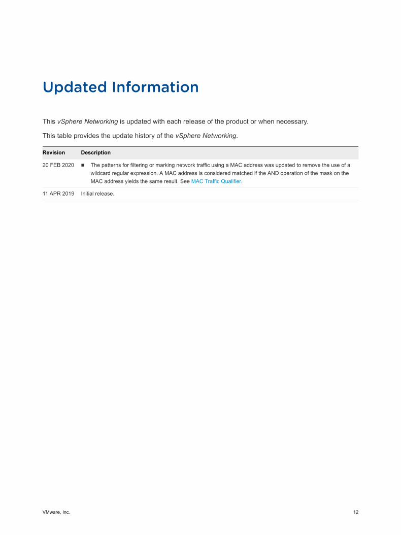
This vSphere Networking is updated with each release of the product or when necessary.
This table provides the update history of the vSphere Networking.
Revision Description
20 FEB 2020 n The patterns for filtering or marking network traffic using a MAC address was updated to remove the use of a wildcard regular expression. A MAC address is considered matched if the AND operation of the mask on the MAC address yields the same result. See MAC Traffic Qualifier.
11 APR 2019 Initial release.
VMware, Inc. 12
Introduction to vSphere Networking 1Get to know the basic concepts of vSphere networking and how to set up and configure a network in a vSphere environment.
This chapter includes the following topics:
n Networking Concepts Overview
n Network Services in ESXi
n VMware ESXi Dump Collector Support
Networking Concepts OverviewA few concepts are essential for a thorough understanding of virtual networking. If you are new to vSphere, it is helpful to review these concepts.
Physical Network A network of physical machines that are connected so that they can send data to and receive data from each other. VMware ESXi runs on a physical machine.
Virtual Network A network of virtual machines running on a physical machine that are connected logically to each other so that they can send data to and receive data from each other. Virtual machines can be connected to the virtual networks that you create when you add a network.
Opaque Network An opaque network is a network created and managed by a separate entity outside of vSphere. For example, logical networks that are created and managed by VMware NSX® appear in vCenter Server as opaque networks of the type nsx.LogicalSwitch. You can choose an opaque network as the backing for a VM network adapter. To manage an opaque network, use the management tools associated with the opaque network, such as VMware NSX® Manager or the VMware NSX API management tools.
Physical Ethernet Switch
A physical ethernet switch manages network traffic between machines on the physical network. A switch has multiple ports, each of which can be connected to a single machine or another switch on the network. Each port can be configured to behave in certain ways depending on the needs of the
VMware, Inc. 13
machine connected to it. The switch learns which hosts are connected to which of its ports and uses that information to forward traffic to the correct physical machines. Switches are the core of a physical network. Multiple switches can be connected together to form larger networks.
vSphere Standard Switch
It works much like a physical Ethernet switch. It detects which virtual machines are logically connected to each of its virtual ports and uses that information to forward traffic to the correct virtual machines. A vSphere standard switch can be connected to physical switches by using physical Ethernet adapters, also referred to as uplink adapters, to join virtual networks with physical networks. This type of connection is similar to connecting physical switches together to create a larger network. Even though a vSphere standard switch works much like a physical switch, it does not have some of the advanced functionality of a physical switch.
Standard Port Group Network services connect to standard switches through port groups. Port groups define how a connection is made through the switch to the network. Typically, a single standard switch is associated with one or more port groups. A port group specifies port configuration options such as bandwidth limitations and VLAN tagging policies for each member port.
vSphere Distributed Switch
A vSphere distributed switch acts as a single switch across all associated hosts in a data center to provide centralized provisioning, administration, and monitoring of virtual networks. You configure a vSphere distributed switch on the vCenter Server system and the configuration is propagated to all hosts that are associated with the switch. This lets virtual machines maintain consistent network configuration as they migrate across multiple hosts.
Host Proxy Switch A hidden standard switch that resides on every host that is associated with a vSphere distributed switch. The host proxy switch replicates the networking configuration set on the vSphere distributed switch to the particular host.
Distributed Port A port on a vSphere distributed switch that connects to a host’s VMkernel or to a virtual machine’s network adapter.
Distributed Port Group A port group associated with a vSphere distributed switch that specifies port configuration options for each member port. Distributed port groups define how a connection is made through the vSphere distributed switch to the network.
NIC Teaming NIC teaming occurs when multiple uplink adapters are associated with a single switch to form a team. A team can either share the load of traffic between physical and virtual networks among some or all of its members, or provide passive failover in the event of a hardware failure or a network outage.
vSphere Networking
VMware, Inc. 14
VLAN VLAN enable a single physical LAN segment to be further segmented so that groups of ports are isolated from one another as if they were on physically different segments. The standard is 802.1Q.
VMkernel TCP/IP Networking Layer
The VMkernel networking layer provides connectivity to hosts and handles the standard infrastructure traffic of vSphere vMotion, IP storage, Fault Tolerance, and vSAN.
IP Storage Any form of storage that uses TCP/IP network communication as its foundation. iSCSI and NFS can be used as virtual machine datastores and for direct mounting of .ISO files, which are presented as CD-ROMs to virtual machines.
TCP Segmentation Offload
TCP Segmentation Offload, TSO, allows a TCP/IP stack to emit large frames (up to 64KB) even though the maximum transmission unit (MTU) of the interface is smaller. The network adapter then separates the large frame into MTU-sized frames and prepends an adjusted copy of the initial TCP/IP headers.
Network Services in ESXiA virtual network provides several services to the host and virtual machines.
You can enable two types of network services in ESXi:
n Connecting virtual machines to the physical network and to each other.
n Connecting VMkernel services (such as NFS, iSCSI, or vMotion) to the physical network.
VMware ESXi Dump Collector SupportThe ESXi Dump Collector sends the state of the VMkernel memory, that is, a core dump to a network server when the system encounters a critical failure.
The ESXi Dump Collector in ESXi supports both vSphere Standard and Distributed Switches. The ESXi Dump Collector can also use any active uplink adapter from the team of the port group that handles the VMkernel adapter for the collector.
Changes to the IP address for the ESXi Dump Collector interface are automatically updated if the IP addresses for the configured VMkernel adapter changes. The ESXi Dump Collector also adjusts its default gateway if the gateway configuration of the VMkernel adapter changes.
If you try to delete the VMkernel network adapter used by the ESXi Dump Collector, the operation fails and a warning message appears. To delete the VMkernel network adapter, disable dump collection and delete the adapter.
There is no authentication or encryption in the file transfer session from a crashed host to the ESXi Dump Collector. You should configure the ESXi Dump Collector on a separate VLAN when possible to isolate the ESXi core dump from regular network traffic.
vSphere Networking
VMware, Inc. 15

For information about installing and configuring the ESXi Dump Collector, see the vCenter Server Installation and Setup documentation.
vSphere Networking
VMware, Inc. 16
Setting Up Networking with vSphere Standard Switches 2vSphere standard switches handle network traffic at the host level in a vSphere deployment.
This chapter includes the following topics:
n vSphere Standard Switches
n Create a vSphere Standard Switch
n Port Group Configuration for Virtual Machines
n vSphere Standard Switch Properties
vSphere Standard SwitchesYou can create abstracted network devices called vSphere Standard Switches. You use standard switches to provide network connectivity to hosts and virtual machines. A standard switch can bridge traffic internally between virtual machines in the same VLAN and link to external networks.
Standard Switch OverviewTo provide network connectivity to hosts and virtual machines, you connect the physical NICs of the hosts to uplink ports on the standard switch. Virtual machines have network adapters (vNICs) that you connect to port groups on the standard switch. Every port group can use one or more physical NICs to handle their network traffic. If a port group does not have a physical NIC connected to it, virtual machines on the same port group can only communicate with each other but not with the external network.
VMware, Inc. 17

Figure 2-1. vSphere Standard Switch architecture
Managementtraffic
vMotiontraffic
Virtualport
vmknic
VMVMVMVM VMVMVMVM
vminc0 vminc1 vminc3
Uplink port groupuplink port 0 uplink port 1 uplink port 2
ESXi host 2
ManagementvMotionTestenvironmentProductionManagement
Managementtraffic
vMotion
vMotiontraffic
Testenvironment Production
Physical network adapters
Physical Switch
vminc0 vminc1 vminc3
Uplink port groupuplink port 0 uplink port 1 uplink port 2
ESXi host 1
vNIC
Networkproduction
Portgroups
A vSphere Standard Switch is very similar to a physical Ethernet switch. Virtual machine network adapters and physical NICs on the host use the logical ports on the switch as each adapter uses one port. Each logical port on the standard switch is a member of a single port group. For information about maximum allowed ports and port groups, see the Configuration Maximums documentation.
Standard Port GroupsEach port group on a standard switch is identified by a network label, which must be unique to the current host. You can use network labels to make the networking configuration of virtual machines portable across hosts. You should give the same label to the port groups in a data center that use physical NICs connected to one broadcast domain on the physical network. Conversely, if two port groups are connected to physical NICs on different broadcast domains, the port groups should have distinct labels.
For example, you can create Production and Test environment port groups as virtual machine networks on the hosts that share the same broadcast domain on the physical network.
A VLAN ID, which restricts port group traffic to a logical Ethernet segment within the physical network, is optional. For port groups to receive the traffic that the same host sees, but from more than one VLAN, the VLAN ID must be set to VGT (VLAN 4095).
vSphere Networking
VMware, Inc. 18
Number of Standard PortsTo ensure efficient use of host resources on ESXi hosts, the number of ports of standard switches are dynamically scaled up and down. A standard switch on such a host can expand up to the maximum number of ports supported on the host.
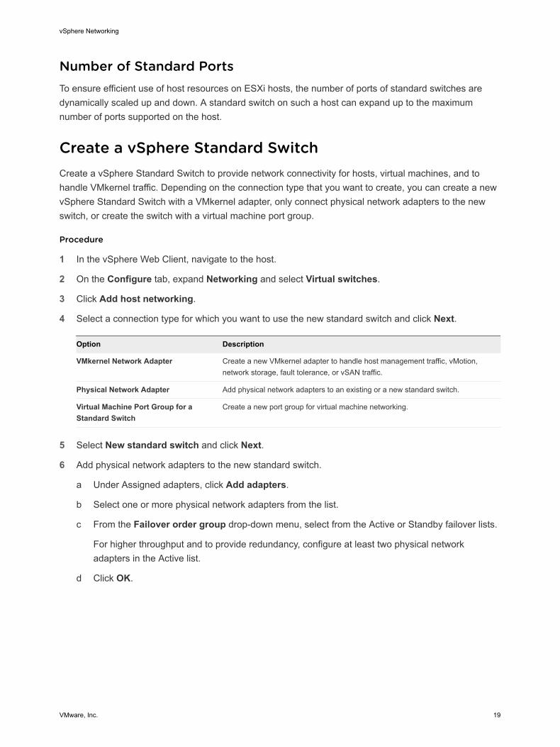
Create a vSphere Standard SwitchCreate a vSphere Standard Switch to provide network connectivity for hosts, virtual machines, and to handle VMkernel traffic. Depending on the connection type that you want to create, you can create a new vSphere Standard Switch with a VMkernel adapter, only connect physical network adapters to the new switch, or create the switch with a virtual machine port group.
Procedure
1 In the vSphere Web Client, navigate to the host.
2 On the Configure tab, expand Networking and select Virtual switches.
3 Click Add host networking.
4 Select a connection type for which you want to use the new standard switch and click Next.
Option Description
VMkernel Network Adapter Create a new VMkernel adapter to handle host management traffic, vMotion, network storage, fault tolerance, or vSAN traffic.
Physical Network Adapter Add physical network adapters to an existing or a new standard switch.
Virtual Machine Port Group for a Standard Switch
Create a new port group for virtual machine networking.
5 Select New standard switch and click Next.
6 Add physical network adapters to the new standard switch.
a Under Assigned adapters, click Add adapters.
b Select one or more physical network adapters from the list.
c From the Failover order group drop-down menu, select from the Active or Standby failover lists.
For higher throughput and to provide redundancy, configure at least two physical network adapters in the Active list.
d Click OK.
vSphere Networking
VMware, Inc. 19
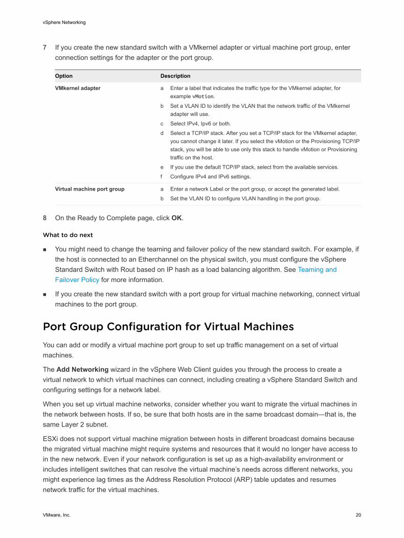
7 If you create the new standard switch with a VMkernel adapter or virtual machine port group, enter connection settings for the adapter or the port group.
Option Description
VMkernel adapter a Enter a label that indicates the traffic type for the VMkernel adapter, for example vMotion.
b Set a VLAN ID to identify the VLAN that the network traffic of the VMkernel adapter will use.
c Select IPv4, Ipv6 or both.
d Select a TCP/IP stack. After you set a TCP/IP stack for the VMkernel adapter, you cannot change it later. If you select the vMotion or the Provisioning TCP/IP stack, you will be able to use only this stack to handle vMotion or Provisioning traffic on the host.
e If you use the default TCP/IP stack, select from the available services.
f Configure IPv4 and IPv6 settings.
Virtual machine port group a Enter a network Label or the port group, or accept the generated label.
b Set the VLAN ID to configure VLAN handling in the port group.
8 On the Ready to Complete page, click OK.
What to do next
n You might need to change the teaming and failover policy of the new standard switch. For example, if the host is connected to an Etherchannel on the physical switch, you must configure the vSphere Standard Switch with Rout based on IP hash as a load balancing algorithm. See Teaming and Failover Policy for more information.
n If you create the new standard switch with a port group for virtual machine networking, connect virtual machines to the port group.
Port Group Configuration for Virtual MachinesYou can add or modify a virtual machine port group to set up traffic management on a set of virtual machines.
The Add Networking wizard in the vSphere Web Client guides you through the process to create a virtual network to which virtual machines can connect, including creating a vSphere Standard Switch and configuring settings for a network label.
When you set up virtual machine networks, consider whether you want to migrate the virtual machines in the network between hosts. If so, be sure that both hosts are in the same broadcast domain—that is, the same Layer 2 subnet.
ESXi does not support virtual machine migration between hosts in different broadcast domains because the migrated virtual machine might require systems and resources that it would no longer have access to in the new network. Even if your network configuration is set up as a high-availability environment or includes intelligent switches that can resolve the virtual machine’s needs across different networks, you might experience lag times as the Address Resolution Protocol (ARP) table updates and resumes network traffic for the virtual machines.
vSphere Networking
VMware, Inc. 20
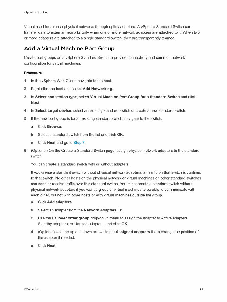
Virtual machines reach physical networks through uplink adapters. A vSphere Standard Switch can transfer data to external networks only when one or more network adapters are attached to it. When two or more adapters are attached to a single standard switch, they are transparently teamed.
Add a Virtual Machine Port GroupCreate port groups on a vSphere Standard Switch to provide connectivity and common network configuration for virtual machines.
Procedure
1 In the vSphere Web Client, navigate to the host.
2 Right-click the host and select Add Networking.
3 In Select connection type, select Virtual Machine Port Group for a Standard Switch and click Next.
4 In Select target device, select an existing standard switch or create a new standard switch.
5 If the new port group is for an existing standard switch, navigate to the switch.
a Click Browse.
b Select a standard switch from the list and click OK.
c Click Next and go to Step 7.
6 (Optional) Оn the Create a Standard Switch page, assign physical network adapters to the standard switch.
You can create a standard switch with or without adapters.
If you create a standard switch without physical network adapters, all traffic on that switch is confined to that switch. No other hosts on the physical network or virtual machines on other standard switches can send or receive traffic over this standard switch. You might create a standard switch without physical network adapters if you want a group of virtual machines to be able to communicate with each other, but not with other hosts or with virtual machines outside the group.
a Click Add adapters.
b Select an adapter from the Network Adapters list.
c Use the Failover order group drop-down menu to assign the adapter to Active adapters, Standby adapters, or Unused adapters, and click OK.
d (Optional) Use the up and down arrows in the Assigned adapters list to change the position of the adapter if needed.
e Click Next.
vSphere Networking
VMware, Inc. 21
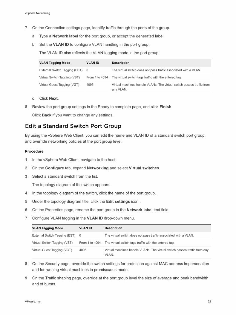
7 On the Connection settings page, identify traffic through the ports of the group.
a Type a Network label for the port group, or accept the generated label.
b Set the VLAN ID to configure VLAN handling in the port group.
The VLAN ID also reflects the VLAN tagging mode in the port group.
VLAN Tagging Mode VLAN ID Description
External Switch Tagging (EST) 0 The virtual switch does not pass traffic associated with a VLAN.
Virtual Switch Tagging (VST) From 1 to 4094 The virtual switch tags traffic with the entered tag.
Virtual Guest Tagging (VGT) 4095 Virtual machines handle VLANs. The virtual switch passes traffic from any VLAN.
c Click Next.
8 Review the port group settings in the Ready to complete page, and click Finish.
Click Back if you want to change any settings.
Edit a Standard Switch Port GroupBy using the vSphere Web Client, you can edit the name and VLAN ID of a standard switch port group, and override networking policies at the port group level.
Procedure
1 In the vSphere Web Client, navigate to the host.
2 On the Configure tab, expand Networking and select Virtual switches.
3 Select a standard switch from the list.
The topology diagram of the switch appears.
4 In the topology diagram of the switch, click the name of the port group.
5 Under the topology diagram title, click the Edit settings icon .
6 On the Properties page, rename the port group in the Network label text field.
7 Configure VLAN tagging in the VLAN ID drop-down menu.
VLAN Tagging Mode VLAN ID Description
External Switch Tagging (EST) 0 The virtual switch does not pass traffic associated with a VLAN.
Virtual Switch Tagging (VST) From 1 to 4094 The virtual switch tags traffic with the entered tag.
Virtual Guest Tagging (VGT) 4095 Virtual machines handle VLANs. The virtual switch passes traffic from any VLAN.
8 On the Security page, override the switch settings for protection against MAC address impersonation and for running virtual machines in promiscuous mode.
9 On the Traffic shaping page, override at the port group level the size of average and peak bandwidth and of bursts.
vSphere Networking
VMware, Inc. 22
10 On the Teaming and failover page, override the teaming and failover settings inherited from the standard switch.
You can configure traffic distribution and rerouting between the physical adapters associated with the port group. You can also change the order in which host physical adapters are used upon failure.
11 Click OK.
Remove a Port Group from a vSphere Standard SwitchYou can remove port groups from vSphere Standard Switches in case you no longer need the associated labeled networks.
Prerequisites
Verify that there are no powered-on virtual machines connected to the port group that you want to remove.
Procedure
1 In the vSphere Web Client, navigate to the host.
2 On the Configure tab, expand Networking and select Virtual switches.
3 Select the standard switch.
4 From the topology diagram of the switch, select the port group that you want to remove by clicking its label.
5 From the toolbar in the switch topology, click the Remove selected port group action icon .
vSphere Standard Switch PropertiesvSphere Standard Switch settings control switch-wide defaults for ports, which can be overridden by port group settings for each standard switch. You can edit standard switch properties, such as the uplink configuration and the number of available ports.
Number of Ports on ESXi HostsTo ensure efficient use of host resources on ESXi hosts, the ports of virtual switches are dynamically scaled up and down. A switch on such a host can expand up to the maximum number of ports supported on the host. The port limit is determined based on the maximum number of virtual machines that the host can handle.
Change the Size of the MTU on a vSphere Standard SwitchChange the size of the maximum transmission unit (MTU) on a vSphere Standard Switch to improve the networking efficiency by increasing the amount of payload data transmitted with a single packet, that is, enabling jumbo frames.
vSphere Networking
VMware, Inc. 23
Procedure
1 In the vSphere Web Client, navigate to the host.
2 On the Configure tab, expand Networking and select Virtual switches.
3 Select a standard switch from the table and click Edit settings.
4 Change the MTU (Bytes) value for the standard switch.
You can enable jumbo frames by setting an MTU value greater than 1500. You cannot set an MTU size greater than 9000 bytes.
5 Click OK.
Change the Speed of a Physical AdapterA physical adapter can become a bottleneck for network traffic if the adapter speed does not match application requirements. You can change the connection speed and duplex of a physical adapter to transfer data in compliance with the traffic rate.
If the physical adapter supports SR-IOV, you can enable it and configure the number of virtual functions to use for virtual machine networking.
Procedure
1 In the vSphere Web Client, navigate to a host.
2 On the Configure tab, expand Networking and select Physical adapters.
The physical network adapters of the host appear in a table that contains details for each physical network adapter.
3 Select the physical network adapter from the list and click the Edit adapter settings icon.
4 Select speed and duplex mode of the physical network adapter from the drop-down menu.
5 Click OK.
Add and Team Physical Adapters in a vSphere Standard SwitchAssign a physical adapter to a standard switch to provide connectivity to virtual machines and VMkernel adapters on the host. You can form a team of NICs to distribute traffic load and to configure failover.
NIC teaming combines multiple network connections to increase throughput and provide redundancy should a link fail. To create a team, you associate multiple physical adapters to a single vSphere Standard Switch.
Procedure
1 In the vSphere Web Client, navigate to the host.
2 On the Configure tab, expand Networking and select Virtual switches.
3 Select the standard switch you want to add a physical adapter to.
4 Click the Manage the physical network adapters connected to the selected switch icon.
vSphere Networking
VMware, Inc. 24

5 Add one or more available physical network adapters to the switch.
a Click Add adapters.
b Select the failover order group to assign the adapters to.
The failover group determines the role of the adapter for exchanging data with the external network, that is, active, standby or unused. By default, the adapters are added as active to the standard switch.
c Click OK
The selected adapters appear in the selected failover group list under the Assigned Adapters list.
6 (Optional) Use the up and down arrows to change the position of an adapter in the failover groups.
7 Click OK to apply the physical adapter configuration.
View the Topology Diagram of a vSphere Standard SwitchYou can examine the structure and components of a vSphere Standard Switch by using its topology diagram.
The topology diagram of a standard switch provides a visual representation of the adapters and port groups connected to the switch.
From the diagram you can edit the settings of a selected port group and of a selected adapter.
Procedure
1 In the vSphere Web Client, navigate to the host.
2 On the Configure tab, expand Networking and select Virtual switches.
3 Select the standard switch from the list.
Results
The diagram appears under the list of virtual switches on the host.
Example: Diagram of a Standard Switch That Connects the VMkernel and Virtual Machines to the NetworkIn your virtual environment, a vSphere Standard Switch handles VMkernel adapters for vSphere vMotion and for the management network, and virtual machines grouped. You can use the central topology diagram to examine whether a virtual machine or VMkernel adapter is connected to the external network and to identify the physical adapter that carries the data.
vSphere Networking
VMware, Inc. 25
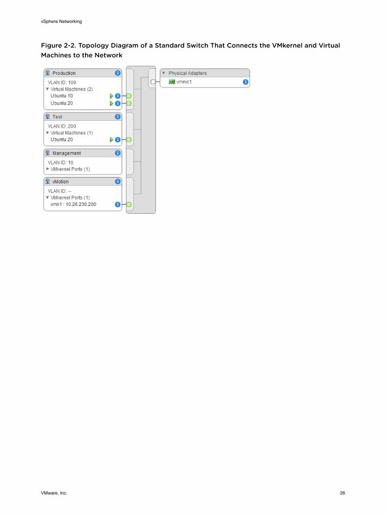
Figure 2-2. Topology Diagram of a Standard Switch That Connects the VMkernel and Virtual Machines to the Network
vSphere Networking
VMware, Inc. 26
Setting Up Networking with vSphere Distributed Switches 3With vSphere distributed switches you can set up and configure networking in a vSphere environment.
This chapter includes the following topics:
n vSphere Distributed Switch Architecture
n Create a vSphere Distributed Switch
n Upgrade a vSphere Distributed Switch to a Later Version
n Edit General and Advanced vSphere Distributed Switch Settings
n Managing Networking on Multiple Hosts on a vSphere Distributed Switch
n Managing Networking on Host Proxy Switches
n Distributed Port Groups
n Working with Distributed Ports
n Configuring Virtual Machine Networking on a vSphere Distributed Switch
n Topology Diagrams of a vSphere Distributed Switch in the vSphere Web Client
vSphere Distributed Switch ArchitectureA vSphere Distributed Switch provides centralized management and monitoring of the networking configuration of all hosts that are associated with the switch. You set up a distributed switch on a vCenter Server system, and its settings are propagated to all hosts that are associated with the switch.
VMware, Inc. 27
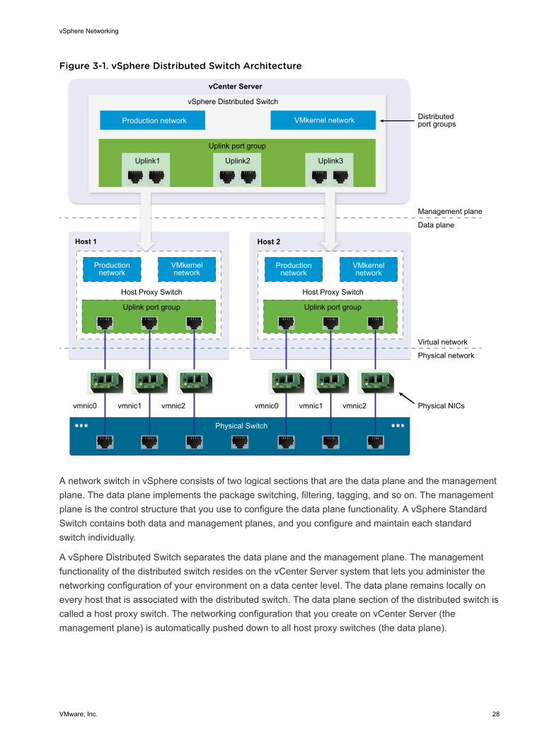
Figure 3-1. vSphere Distributed Switch Architecture
Uplink port group Uplink port group
Uplink2 Uplink3Uplink1
Host 1 Host 2
Uplink port group
vSphere Distributed Switch
vCenter Server
Distributedport groups Production network VMkernel network
vmnic0 vmnic1 vmnic2 vmnic0 vmnic1 vmnic2
Host Proxy Switch
Production network
VMkernelnetwork
Production network
VMkernelnetwork
Management plane
Data plane
Virtual network
Physical network
Physical NICs
Host Proxy Switch
Physical Switch
A network switch in vSphere consists of two logical sections that are the data plane and the management plane. The data plane implements the package switching, filtering, tagging, and so on. The management plane is the control structure that you use to configure the data plane functionality. A vSphere Standard Switch contains both data and management planes, and you configure and maintain each standard switch individually.
A vSphere Distributed Switch separates the data plane and the management plane. The management functionality of the distributed switch resides on the vCenter Server system that lets you administer the networking configuration of your environment on a data center level. The data plane remains locally on every host that is associated with the distributed switch. The data plane section of the distributed switch is called a host proxy switch. The networking configuration that you create on vCenter Server (the management plane) is automatically pushed down to all host proxy switches (the data plane).
vSphere Networking
VMware, Inc. 28
The vSphere Distributed Switch introduces two abstractions that you use to create consistent networking configuration for physical NICs, virtual machines, and VMkernel services.
Uplink port group An uplink port group or dvuplink port group is defined during the creation of the distributed switch and can have one or more uplinks. An uplink is a template that you use to configure physical connections of hosts as well as failover and load balancing policies. You map physical NICs of hosts to uplinks on the distributed switch. At the host level, each physical NIC is connected to an uplink port with a particular ID. You set failover and load balancing policies over uplinks and the policies are automatically propagated to the host proxy switches, or the data plane. In this way you can apply consistent failover and load balancing configuration for the physical NICs of all hosts that are associated with the distributed switch.
Distributed port group Distributed port groups provide network connectivity to virtual machines and accommodate VMkernel traffic. You identify each distributed port group by using a network label, which must be unique to the current data center. You configure NIC teaming, failover, load balancing, VLAN, security, traffic shaping , and other policies on distributed port groups. The virtual ports that are connected to a distributed port group share the same properties that are configured to the distributed port group. As with uplink port groups, the configuration that you set on distributed port groups on vCenter Server (the management plane) is automatically propagated to all hosts on the distributed switch through their host proxy switches (the data plane). In this way you can configure a group of virtual machines to share the same networking configuration by associating the virtual machines to the same distributed port group.
For example, suppose that you create a vSphere Distributed Switch on your data center and associate two hosts with it. You configure three uplinks to the uplink port group and connect a physical NIC from each host to an uplink. In this way, each uplink has two physical NICs from each host mapped to it, for example Uplink 1 is configured with vmnic0 from Host 1 and Host 2. Next you create the Production and the VMkernel network distributed port groups for virtual machine networking and VMkernel services. Respectively, a representation of the Production and the VMkernel network port groups is also created on Host 1 and Host 2. All policies that you set to the Production and the VMkernel network port groups are propagated to their representations on Host 1 and Host 2.
To ensure efficient use of host resources, the number of distributed ports of proxy switches is dynamically scaled up and down. A proxy switch on such a host can expand up to the maximum number of ports supported on the host. The port limit is determined based on the maximum number of virtual machines that the host can handle.
vSphere Networking
VMware, Inc. 29
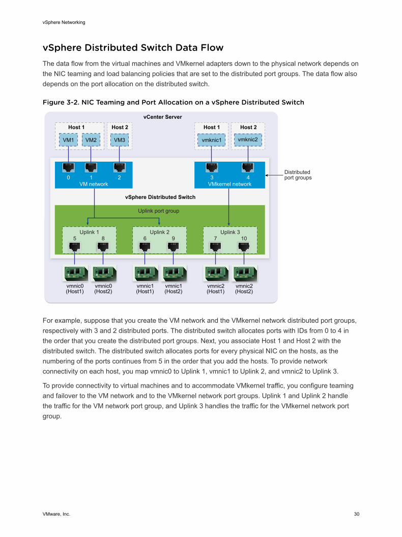
vSphere Distributed Switch Data FlowThe data flow from the virtual machines and VMkernel adapters down to the physical network depends on the NIC teaming and load balancing policies that are set to the distributed port groups. The data flow also depends on the port allocation on the distributed switch.
Figure 3-2. NIC Teaming and Port Allocation on a vSphere Distributed Switch
VMkernel network
vCenter Server
Uplink port group
vSphere Distributed Switch
Host 1
Distributedport groups3 4
Host 1 Host 2
vmknic2
Host 2
VM network0 1 2
vmknic1
Uplink 26
vmnic1(Host1)
9
vmnic1(Host2)
Uplink 37
vmnic2(Host1)
10
vmnic2(Host2)
VM1 VM2 VM3
5
vmnic0(Host1)
8
vmnic0(Host2)
Uplink 1
For example, suppose that you create the VM network and the VMkernel network distributed port groups, respectively with 3 and 2 distributed ports. The distributed switch allocates ports with IDs from 0 to 4 in the order that you create the distributed port groups. Next, you associate Host 1 and Host 2 with the distributed switch. The distributed switch allocates ports for every physical NIC on the hosts, as the numbering of the ports continues from 5 in the order that you add the hosts. To provide network connectivity on each host, you map vmnic0 to Uplink 1, vmnic1 to Uplink 2, and vmnic2 to Uplink 3.
To provide connectivity to virtual machines and to accommodate VMkernel traffic, you configure teaming and failover to the VM network and to the VMkernel network port groups. Uplink 1 and Uplink 2 handle the traffic for the VM network port group, and Uplink 3 handles the traffic for the VMkernel network port group.
vSphere Networking
VMware, Inc. 30
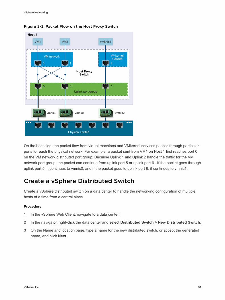
Figure 3-3. Packet Flow on the Host Proxy Switch
VMkernelnetwork
Uplink port group
VM network
Host 1
0 1 3
vmnic0 vmnic1
5 6 7
Host ProxySwitch
vmnic2
VM2 vmknic1VM1
Physical Switch
On the host side, the packet flow from virtual machines and VMkernel services passes through particular ports to reach the physical network. For example, a packet sent from VM1 on Host 1 first reaches port 0 on the VM network distributed port group. Because Uplink 1 and Uplink 2 handle the traffic for the VM network port group, the packet can continue from uplink port 5 or uplink port 6 . If the packet goes through uplink port 5, it continues to vmnic0, and if the packet goes to uplink port 6, it continues to vmnic1.
Create a vSphere Distributed SwitchCreate a vSphere distributed switch on a data center to handle the networking configuration of multiple hosts at a time from a central place.
Procedure
1 In the vSphere Web Client, navigate to a data center.
2 In the navigator, right-click the data center and select Distributed Switch > New Distributed Switch.
3 On the Name and location page, type a name for the new distributed switch, or accept the generated name, and click Next.
vSphere Networking
VMware, Inc. 31
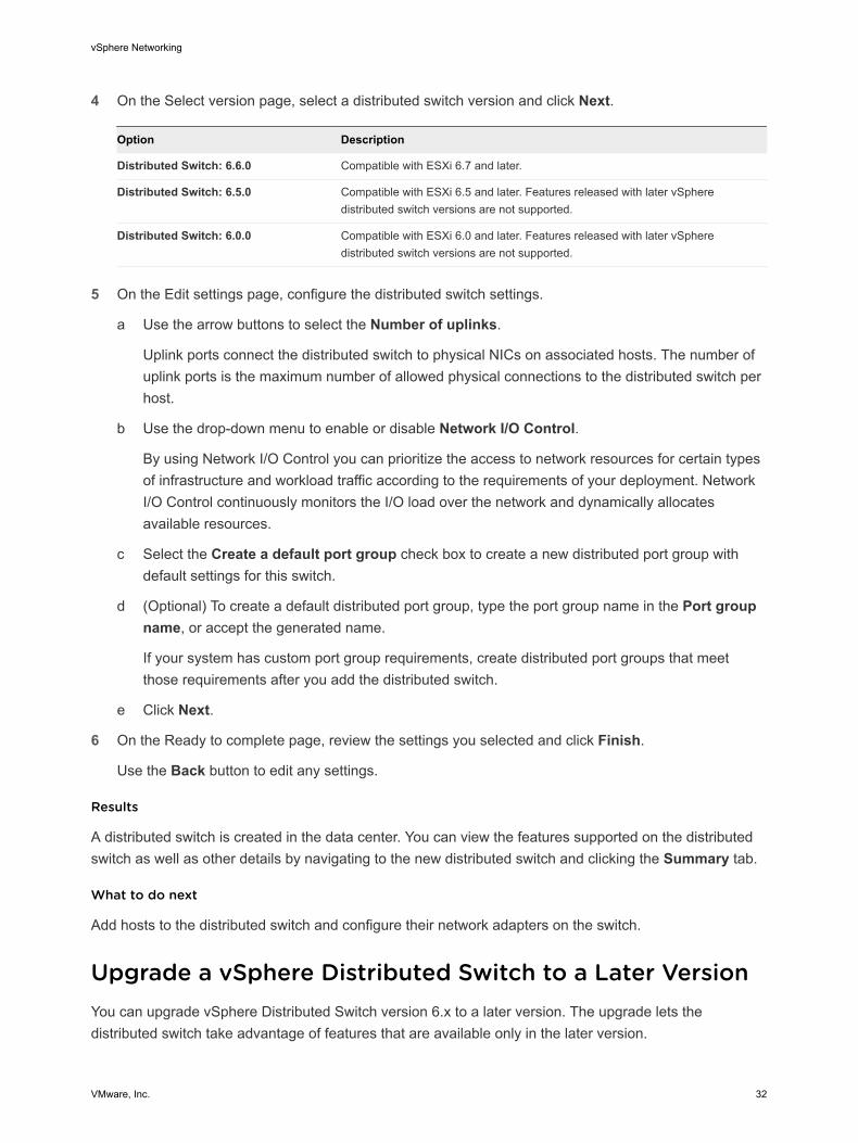
4 On the Select version page, select a distributed switch version and click Next.
Option Description
Distributed Switch: 6.6.0 Compatible with ESXi 6.7 and later.
Distributed Switch: 6.5.0 Compatible with ESXi 6.5 and later. Features released with later vSphere distributed switch versions are not supported.
Distributed Switch: 6.0.0 Compatible with ESXi 6.0 and later. Features released with later vSphere distributed switch versions are not supported.
5 On the Edit settings page, configure the distributed switch settings.
a Use the arrow buttons to select the Number of uplinks.
Uplink ports connect the distributed switch to physical NICs on associated hosts. The number of uplink ports is the maximum number of allowed physical connections to the distributed switch per host.
b Use the drop-down menu to enable or disable Network I/O Control.
By using Network I/O Control you can prioritize the access to network resources for certain types of infrastructure and workload traffic according to the requirements of your deployment. Network I/O Control continuously monitors the I/O load over the network and dynamically allocates available resources.
c Select the Create a default port group check box to create a new distributed port group with default settings for this switch.
d (Optional) To create a default distributed port group, type the port group name in the Port group name, or accept the generated name.
If your system has custom port group requirements, create distributed port groups that meet those requirements after you add the distributed switch.
e Click Next.
6 On the Ready to complete page, review the settings you selected and click Finish.
Use the Back button to edit any settings.
Results
A distributed switch is created in the data center. You can view the features supported on the distributed switch as well as other details by navigating to the new distributed switch and clicking the Summary tab.
What to do next
Add hosts to the distributed switch and configure their network adapters on the switch.
Upgrade a vSphere Distributed Switch to a Later VersionYou can upgrade vSphere Distributed Switch version 6.x to a later version. The upgrade lets the distributed switch take advantage of features that are available only in the later version.
vSphere Networking
VMware, Inc. 32

The upgrade of a distributed switch causes the hosts and virtual machines attached to the switch to experience a brief downtime. For more information, see KB 52621.
Note To be able to restore the connectivity of the virtual machines and VMkernel adapters if the upgrade fails, back up the configuration of the distributed switch.
If the upgrade is not successful, to recreate the switch with its port groups and connected hosts, you can import the switch configuration file. See Export vSphere Distributed Switch Configurations and Import a vSphere Distributed Switch Configuration.
Prerequisites
n Upgrade vCenter Server to version 6.7.
n Upgrade all hosts connected to the distributed switch to ESXi 6.7.
Procedure
1 In the vSphere Web Client, navigate to the distributed switch.
2 Right-click the distributed switch and select Upgrade > Upgrade Distributed Switch.
3 Select the vSphere Distributed Switch version that you want to upgrade the switch to and click Next.
Option Description
Version 6.6.0 Compatible with ESXi version 6.7 and later.
Version 6.5.0 Compatible with ESXi version 6.5 and later. Features released with later vSphere Distributed Switch versions are not supported.
Version 6.0.0 Compatible with ESXi version 6.0 and later. Features released with later vSphere Distributed Switch versions are not supported.
4 Review host compatibility and click Next.
Some ESXi instances that are connected to the distributed switch might be incompatible with the selected target version. Upgrade or remove the incompatible hosts, or select another upgrade version for the distributed switch.
5 Complete the upgrade configuration and click Finish.
Caution After you upgrade the vSphere Distributed Switch, you cannot revert it to an earlier version. You also cannot add ESXi hosts that are running an earlier version than the new version of the switch.
Edit General and Advanced vSphere Distributed Switch SettingsGeneral settings for a vSphere Distributed Switch include the switch name and number of uplinks. Advanced settings for a distributed switch include Cisco Discovery Protocol and the maximum MTU for the switch.
vSphere Networking
VMware, Inc. 33
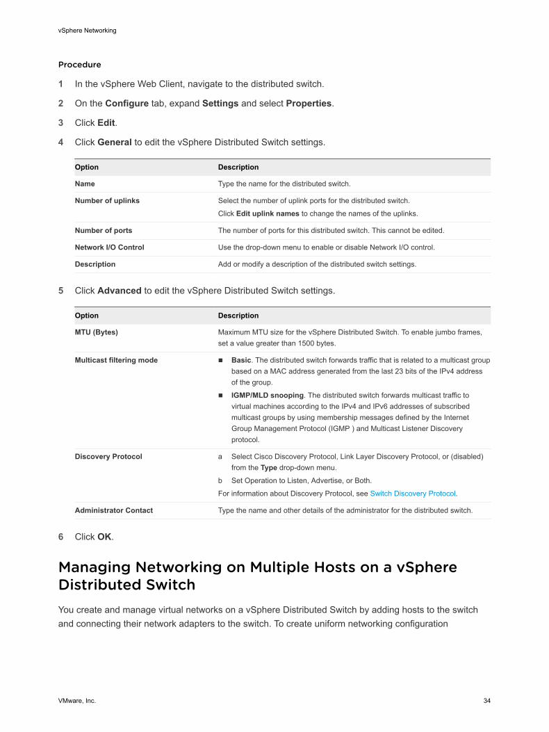
Procedure
1 In the vSphere Web Client, navigate to the distributed switch.
2 On the Configure tab, expand Settings and select Properties.
3 Click Edit.
4 Click General to edit the vSphere Distributed Switch settings.
Option Description
Name Type the name for the distributed switch.
Number of uplinks Select the number of uplink ports for the distributed switch.
Click Edit uplink names to change the names of the uplinks.
Number of ports The number of ports for this distributed switch. This cannot be edited.
Network I/O Control Use the drop-down menu to enable or disable Network I/O control.
Description Add or modify a description of the distributed switch settings.
5 Click Advanced to edit the vSphere Distributed Switch settings.
Option Description
MTU (Bytes) Maximum MTU size for the vSphere Distributed Switch. To enable jumbo frames, set a value greater than 1500 bytes.
Multicast filtering mode n Basic. The distributed switch forwards traffic that is related to a multicast group based on a MAC address generated from the last 23 bits of the IPv4 address of the group.
n IGMP/MLD snooping. The distributed switch forwards multicast traffic to virtual machines according to the IPv4 and IPv6 addresses of subscribed multicast groups by using membership messages defined by the Internet Group Management Protocol (IGMP ) and Multicast Listener Discovery protocol.
Discovery Protocol a Select Cisco Discovery Protocol, Link Layer Discovery Protocol, or (disabled) from the Type drop-down menu.
b Set Operation to Listen, Advertise, or Both.
For information about Discovery Protocol, see Switch Discovery Protocol.
Administrator Contact Type the name and other details of the administrator for the distributed switch.
6 Click OK.
Managing Networking on Multiple Hosts on a vSphere Distributed SwitchYou create and manage virtual networks on a vSphere Distributed Switch by adding hosts to the switch and connecting their network adapters to the switch. To create uniform networking configuration
vSphere Networking
VMware, Inc. 34
throughout multiple hosts on the distributed switch, you can use a host as a template and apply its configuration to other hosts.
n Tasks for Managing Host Networking on a vSphere Distributed Switch
You can add new hosts to a vSphere Distributed Switch, connect network adapters to the switch, and remove hosts from the switch. In a production environment, you might need to keep the network connectivity up for virtual machines and VMkernel services while you manage host networking on the distributed switch.
n Add Hosts to a vSphere Distributed Switch
To manage the networking of your vSphere environment by using a vSphere Distributed Switch, you must associate hosts with the switch. You connect the physical NICs, VMkernel adapters, and virtual machine network adapters of the hosts to the distributed switch.
n Configure Physical Network Adapters on a vSphere Distributed Switch
For hosts that are associated with a distributed switch, you can assign physical NICs to uplinks on the switch. You can configure physical NICs on the distributed switch for multiple hosts at a time.
n Migrate VMkernel Adapters to a vSphere Distributed Switch
Migrate VMkernel adapters to a distributed switch if you want to handle the traffic for VMkernel services by using only this switch and you no longer need the adapters on other standard or distributed switches.
n Create a VMkernel Adapter on a vSphere Distributed Switch
Create a VMkernel adapter on hosts associated with a distributed switch to provide network connectivity to the hosts and to handle the traffic for vSphere vMotion, IP storage, Fault Tolerance logging, and vSAN. You can create VMkernel adapters on multiple hosts simultaneously by using the Add and Manage Hosts wizard.
n Migrate Virtual Machine Networking to the vSphere Distributed Switch
To manage virtual machine networking by using a distributed switch, migrate virtual machine network adapters to labeled networks on the switch.
n Use a Host as a Template to Create a Uniform Networking Configuration on a vSphere Distributed Switch
If you plan to have hosts with a uniform networking configuration, you can select a host as a template and apply its configuration for physical NICs and VMkernel adapters to other hosts on the distributed switch.
n Remove Hosts from a vSphere Distributed Switch
Remove hosts from a vSphere distributed switch if you have configured a different switch for the hosts.
Tasks for Managing Host Networking on a vSphere Distributed SwitchYou can add new hosts to a vSphere Distributed Switch, connect network adapters to the switch, and remove hosts from the switch. In a production environment, you might need to keep the network
vSphere Networking
VMware, Inc. 35
connectivity up for virtual machines and VMkernel services while you manage host networking on the distributed switch.
Adding Hosts to a vSphere Distributed SwitchConsider preparing your environment before you add new hosts to a distributed switch.
n Create distributed port groups for virtual machine networking.
n Create distributed port groups for VMkernel services. For example, create distributed port groups for management network, vMotion, and Fault Tolerance.
n Configure enough uplinks on the distributed switch for all physical NICs that you want to connect to the switch. For example, if the hosts that you want to connect to the distributed switch have eight physical NICs each, configure eight uplinks on the distributed switch.
n Make sure that the configuration of the distributed switch is prepared for services with specific networking requirements. For example, iSCSI has specific requirements for the teaming and failover configuration of the distributed port group where you connect the iSCSI VMkernel adapter.
You can use the Add and Manage Hosts wizard in the vSphere Web Client to add multiple hosts at a time.
Managing Network Adapters on a vSphere Distributed SwitchAfter you add hosts to a distributed switch, you can connect physical NICs to uplinks on the switch, configure virtual machine network adapters, and manage VMkernel networking.
If some hosts on a distributed switch are associated to other switches in your data center, you can migrate network adapters to or from the distributed switch.
If you migrate virtual machine network adapters or VMkernel adapters, make sure that the destination distributed port groups have at least one active uplink, and the uplink is connected to a physical NIC on the hosts. Another approach is to migrate physical NICs, virtual network adapters, and VMkernel adapters simultaneously.
If you migrate physical NICs, leave at least one active NIC that handles the traffic of port groups. For example, if vmnic0 and vmnic1 handle the traffic of the VM Network port group, migrate vmnic0 and leave vmnic1 connected to the group.
Removing Hosts from a vSphere Distributed SwitchBefore you remove hosts from a distributed switch, you must migrate the network adapters that are in use to a different switch.
n To add hosts to a different distributed switch, you can use the Add and Manage Hosts wizard to migrate the network adapters on the hosts to the new switch all together. You can then remove the hosts safely from their current distributed switch.
n To migrate host networking to standard switches, you must migrate the network adapters in stages. For example, remove physical NICs on the hosts from the distributed switch by leaving one physical
vSphere Networking
VMware, Inc. 36

NIC on every host connected to the switch to keep the network connectivity up. Next, attach the physical NICs to the standard switches and migrate VMkernel adapters and virtual machine network adapters to the switches. Lastly, migrate the physical NIC that you left connected to the distributed switch to the standard switches.
Add Hosts to a vSphere Distributed SwitchTo manage the networking of your vSphere environment by using a vSphere Distributed Switch, you must associate hosts with the switch. You connect the physical NICs, VMkernel adapters, and virtual machine network adapters of the hosts to the distributed switch.
Prerequisites
n Verify that enough uplinks are available on the distributed switch to assign to the physical NICs that you want to connect to the switch.
n Verify that there is at least one distributed port group on the distributed switch.
n Verify that the distributed port group have active uplinks configured in its teaming and failover policy.
If you migrate or create VMkernel adapters for iSCSI, verify that the teaming and failover policy of the target distributed port group meets the requirements for iSCSI:
n Verify that only one uplink is active, the standby list is empty, and the rest of the uplinks are unused.
n Verify that only one physical NIC per host is assigned to the active uplink.
Procedure
1 In the vSphere Web Client, navigate to the distributed switch.
2 From the Actions menu, select Add and Manage Hosts.
3 On the Select task page, select Add hosts, and click Next.
4 On the Select hosts page, click New hosts, select from the hosts in your data center, click OK, and then click Next.
5 On the Select network adapter tasks page, select the tasks for configuring network adapters to the distributed switch and click Next.
6 On the Manage physical network adapters page, configure physical NICs on the distributed switch.
a From the On other switches/unclaimed list, select a physical NIC.
If you select physical NICs that are already connected to other switches, they are migrated to the current distributed switch.
b Click Assign uplink.
c Select an uplink and click OK.
For consistent network configuration, you can connect one and the same physical NIC on every host to the same uplink on the distributed switch.
vSphere Networking
VMware, Inc. 37
For example, if you are adding two hosts connect vmnic1 on of each host to Uplink1 on the distributed switch.
7 Click Next.
8 On the Manage VMkernel network adapters page, configure VMkernel adapters.
a Select a VMkernel adapter and click Assign port group.
b Select a distributed port group and click OK.
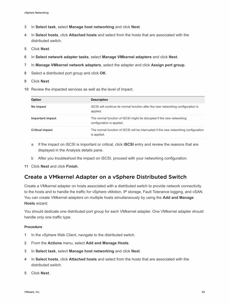
9 Review the impacted services as well as the level of impact.
Option Description
No impact iSCSI will continue its normal function after the new networking configuration is applied.
Important impact The normal function of iSCSI might be disrupted if the new networking configuration is applied.
Critical impact The normal function of iSCSI will be interrupted if the new networking configuration is applied.
a If the impact on iSCSI is important or critical, click iSCSI entry and review the reasons that are
displayed in the Analysis details pane.
b After you troubleshoot the impact on iSCSI, proceed with your networking configuration.
10 Click Next.
11 On the Migrate VM networking page, configure virtual machine networking.
a To connect all network adapters of a virtual machine to a distributed port group, select the virtual machine, or select an individual network adapter to connect only that adapter.
b Click Assign port group.
c Select a distributed port group from the list and click OK.
12 Click Next and click Finish.
What to do next
Having hosts associated with the distributed switch, you can manage physical NICs, VMkernel adapters, and virtual machine network adapters.
Configure Physical Network Adapters on a vSphere Distributed SwitchFor hosts that are associated with a distributed switch, you can assign physical NICs to uplinks on the switch. You can configure physical NICs on the distributed switch for multiple hosts at a time.
For consistent networking configuration throughout all hosts, you can assign the same physical NIC on every host to the same uplink on the distributed switch. For example, you can assign vmnic1 from hosts ESXi A and ESXi B to Uplink 1.
vSphere Networking
VMware, Inc. 38
Procedure
1 In the vSphere Web Client, navigate to the distributed switch.
2 From the Actions menu, select Add and Manage Hosts.
3 In Select task, select Manage host networking and click Next.
4 In Select hosts, click Attached hosts and select from the hosts that are associated with the distributed switch.
5 Click Next.
6 In Select network adapter tasks, select Manage physical adapters and click Next.
7 In Manage physical network adapters, select a physical NIC from the On other switches/unclaimed list.
If you select physical NICs that are already assigned to other switches, they are migrated to the current distributed switch.
8 Click Assign uplink.
9 Select an uplink or select Auto-assign.
10 Click Next.
11 Review the impacted services as well as the level of impact.
Option Description
No impact iSCSI will continue its normal function after the new networking configuration is applied.
Important impact The normal function of iSCSI might be disrupted if the new networking configuration is applied.
Critical impact The normal function of iSCSI will be interrupted if the new networking configuration is applied.
a If the impact on iSCSI is important or critical, click iSCSI entry and review the reasons that are
displayed in the Analysis details pane.
b After you troubleshoot the impact on iSCSI, proceed with your networking configuration.
12 Click Next and click Finish.
Migrate VMkernel Adapters to a vSphere Distributed SwitchMigrate VMkernel adapters to a distributed switch if you want to handle the traffic for VMkernel services by using only this switch and you no longer need the adapters on other standard or distributed switches.
Procedure
1 In the vSphere Web Client, navigate to the distributed switch.
2 From the Actions menu, select Add and Manage Hosts.
vSphere Networking
VMware, Inc. 39
3 In Select task, select Manage host networking and click Next.
4 In Select hosts, click Attached hosts and select from the hosts that are associated with the distributed switch.
5 Click Next.
6 In Select network adapter tasks, select Manage VMkernel adapters and click Next.
7 In Manage VMkernel network adapters, select the adapter and click Assign port group.
8 Select a distributed port group and click OK.
9 Click Next.
10 Review the impacted services as well as the level of impact.
Option Description
No impact iSCSI will continue its normal function after the new networking configuration is applied.
Important impact The normal function of iSCSI might be disrupted if the new networking configuration is applied.
Critical impact The normal function of iSCSI will be interrupted if the new networking configuration is applied.
a If the impact on iSCSI is important or critical, click iSCSI entry and review the reasons that are
displayed in the Analysis details pane.
b After you troubleshoot the impact on iSCSI, proceed with your networking configuration.
11 Click Next and click Finish.
Create a VMkernel Adapter on a vSphere Distributed SwitchCreate a VMkernel adapter on hosts associated with a distributed switch to provide network connectivity to the hosts and to handle the traffic for vSphere vMotion, IP storage, Fault Tolerance logging, and vSAN. You can create VMkernel adapters on multiple hosts simultaneously by using the Add and Manage Hosts wizard.
You should dedicate one distributed port group for each VMkernel adapter. One VMkernel adapter should handle only one traffic type.
Procedure
1 In the vSphere Web Client, navigate to the distributed switch.
2 From the Actions menu, select Add and Manage Hosts.
3 In Select task, select Manage host networking and click Next.
4 In Select hosts, click Attached hosts and select from the hosts that are associated with the distributed switch.
5 Click Next.
vSphere Networking
VMware, Inc. 40
6 In Select network adapter tasks, select Manage VMkernel adapters and click Next.
7 Click New adapter.
The Add Networking wizard opens.
8 In Select target device, select a distributed port group, and click Next.
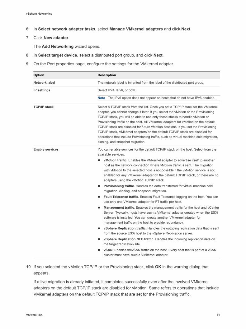
9 On the Port properties page, configure the settings for the VMkernel adapter.
Option Description
Network label The network label is inherited from the label of the distributed port group.
IP settings Select IPv4, IPv6, or both.
Note The IPv6 option does not appear on hosts that do not have IPv6 enabled.
TCP/IP stack Select a TCP/IP stack from the list. Once you set a TCP/IP stack for the VMkernel adapter, you cannot change it later. If you select the vMotion or the Provisioning TCP/IP stack, you will be able to use only these stacks to handle vMotion or Provisioning traffic on the host. All VMkernel adapters for vMotion on the default TCP/IP stack are disabled for future vMotion sessions. If you set the Provisioning TCP/IP stack, VMkernel adapters on the default TCP/IP stack are disabled for operations that include Provisioning traffic, such as virtual machine cold migration, cloning, and snapshot migration.
Enable services You can enable services for the default TCP/IP stack on the host. Select from the available services:
n vMotion traffic. Enables the VMkernel adapter to advertise itself to another host as the network connection where vMotion traffic is sent. The migration with vMotion to the selected host is not possible if the vMotion service is not enabled for any VMkernel adapter on the default TCP/IP stack, or there are no adapters using the vMotion TCP/IP stack.
n Provisioning traffic. Handles the data transferred for virtual machine cold migration, cloning, and snapshot migration.
n Fault Tolerance traffic. Enables Fault Tolerance logging on the host. You can use only one VMkernel adapter for FT traffic per host.
n Management traffic. Enables the management traffic for the host and vCenter Server. Typically, hosts have such a VMkernel adapter created when the ESXi software is installed. You can create another VMkernel adapter for management traffic on the host to provide redundancy.
n vSphere Replication traffic. Handles the outgoing replication data that is sent from the source ESXi host to the vSphere Replication server.
n vSphere Replication NFC traffic. Handles the incoming replication data on the target replication site.
n vSAN. Enables thevSAN traffic on the host. Every host that is part of a vSAN cluster must have such a VMkernel adapter.
10 If you selected the vMotion TCP/IP or the Provisioning stack, click OK in the warning dialog that
appears.
If a live migration is already initiated, it completes successfully even after the involved VMkernel adapters on the default TCP/IP stack are disabled for vMotion. Same refers to operations that include VMkernel adapters on the default TCP/IP stack that are set for the Provisioning traffic.
vSphere Networking
VMware, Inc. 41
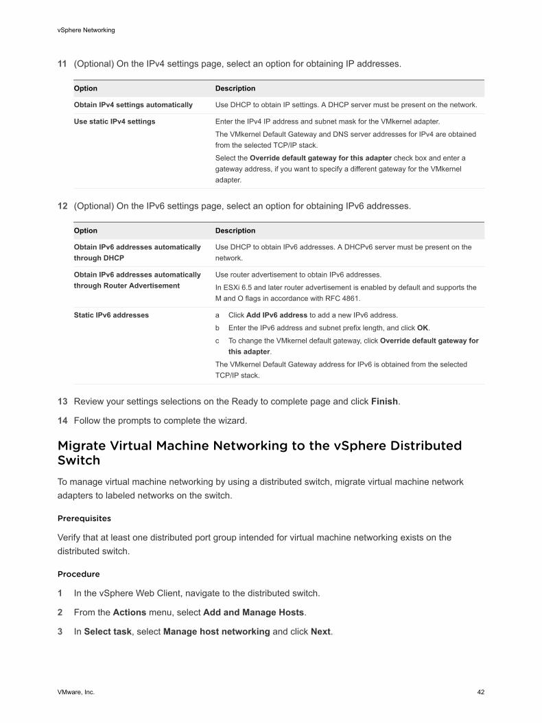
11 (Optional) On the IPv4 settings page, select an option for obtaining IP addresses.
Option Description
Obtain IPv4 settings automatically Use DHCP to obtain IP settings. A DHCP server must be present on the network.
Use static IPv4 settings Enter the IPv4 IP address and subnet mask for the VMkernel adapter.
The VMkernel Default Gateway and DNS server addresses for IPv4 are obtained from the selected TCP/IP stack.
Select the Override default gateway for this adapter check box and enter a gateway address, if you want to specify a different gateway for the VMkernel adapter.
12 (Optional) On the IPv6 settings page, select an option for obtaining IPv6 addresses.
Option Description
Obtain IPv6 addresses automatically through DHCP
Use DHCP to obtain IPv6 addresses. A DHCPv6 server must be present on the network.
Obtain IPv6 addresses automatically through Router Advertisement
Use router advertisement to obtain IPv6 addresses.
In ESXi 6.5 and later router advertisement is enabled by default and supports the M and O flags in accordance with RFC 4861.
Static IPv6 addresses a Click Add IPv6 address to add a new IPv6 address.
b Enter the IPv6 address and subnet prefix length, and click OK.
c To change the VMkernel default gateway, click Override default gateway for this adapter.
The VMkernel Default Gateway address for IPv6 is obtained from the selected TCP/IP stack.
13 Review your settings selections on the Ready to complete page and click Finish.
14 Follow the prompts to complete the wizard.
Migrate Virtual Machine Networking to the vSphere Distributed SwitchTo manage virtual machine networking by using a distributed switch, migrate virtual machine network adapters to labeled networks on the switch.
Prerequisites
Verify that at least one distributed port group intended for virtual machine networking exists on the distributed switch.
Procedure
1 In the vSphere Web Client, navigate to the distributed switch.
2 From the Actions menu, select Add and Manage Hosts.
3 In Select task, select Manage host networking and click Next.
vSphere Networking
VMware, Inc. 42
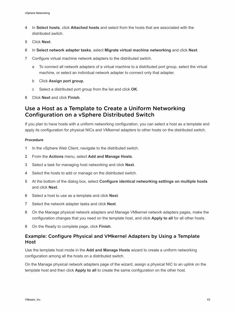
4 In Select hosts, click Attached hosts and select from the hosts that are associated with the distributed switch.
5 Click Next.
6 In Select network adapter tasks, select Migrate virtual machine networking and click Next.
7 Configure virtual machine network adapters to the distributed switch.
a To connect all network adapters of a virtual machine to a distributed port group, select the virtual machine, or select an individual network adapter to connect only that adapter.
b Click Assign port group.
c Select a distributed port group from the list and click OK.
8 Click Next and click Finish.
Use a Host as a Template to Create a Uniform Networking Configuration on a vSphere Distributed SwitchIf you plan to have hosts with a uniform networking configuration, you can select a host as a template and apply its configuration for physical NICs and VMkernel adapters to other hosts on the distributed switch.
Procedure
1 In the vSphere Web Client, navigate to the distributed switch.
2 From the Actions menu, select Add and Manage Hosts.
3 Select a task for managing host networking and click Next.
4 Select the hosts to add or manage on the distributed switch.
5 At the bottom of the dialog box, select Configure identical networking settings on multiple hosts and click Next.
6 Select a host to use as a template and click Next.
7 Select the network adapter tasks and click Next.
8 On the Manage physical network adapters and Manage VMkernel network adapters pages, make the configuration changes that you need on the template host, and click Apply to all for all other hosts.
9 On the Ready to complete page, click Finish.
Example: Configure Physical and VMkernel Adapters by Using a Template HostUse the template host mode in the Add and Manage Hosts wizard to create a uniform networking configuration among all the hosts on a distributed switch.
On the Manage physical network adapters page of the wizard, assign a physical NIC to an uplink on the template host and then click Apply to all to create the same configuration on the other host.
vSphere Networking
VMware, Inc. 43
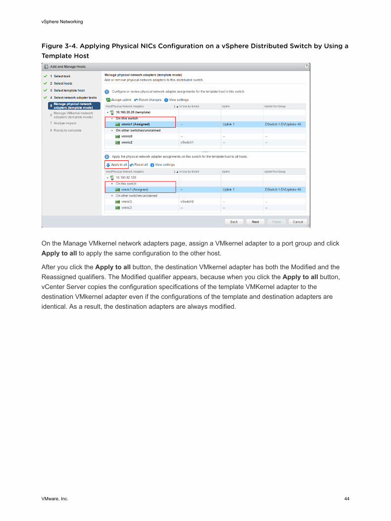
Figure 3-4. Applying Physical NICs Configuration on a vSphere Distributed Switch by Using a Template Host
On the Manage VMkernel network adapters page, assign a VMkernel adapter to a port group and click Apply to all to apply the same configuration to the other host.
After you click the Apply to all button, the destination VMkernel adapter has both the Modified and the Reassigned qualifiers. The Modified qualifier appears, because when you click the Apply to all button, vCenter Server copies the configuration specifications of the template VMKernel adapter to the destination VMkernel adapter even if the configurations of the template and destination adapters are identical. As a result, the destination adapters are always modified.
vSphere Networking
VMware, Inc. 44
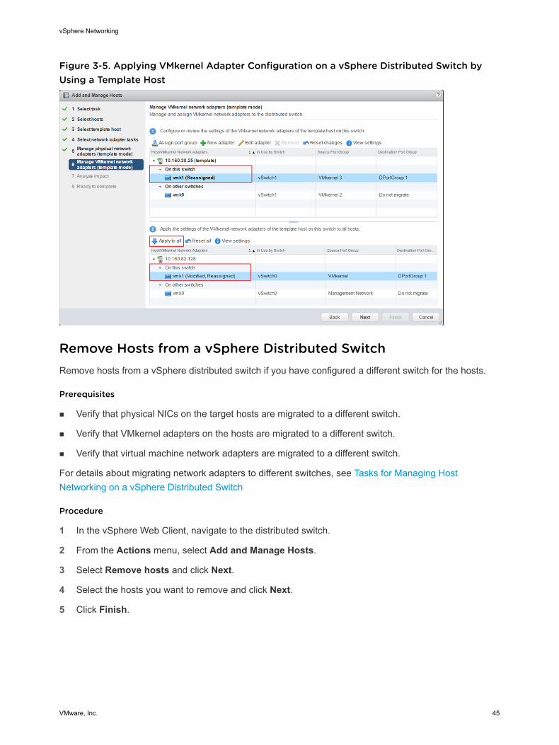
Figure 3-5. Applying VMkernel Adapter Configuration on a vSphere Distributed Switch by Using a Template Host
Remove Hosts from a vSphere Distributed SwitchRemove hosts from a vSphere distributed switch if you have configured a different switch for the hosts.
Prerequisites
n Verify that physical NICs on the target hosts are migrated to a different switch.
n Verify that VMkernel adapters on the hosts are migrated to a different switch.
n Verify that virtual machine network adapters are migrated to a different switch.
For details about migrating network adapters to different switches, see Tasks for Managing Host Networking on a vSphere Distributed Switch
Procedure
1 In the vSphere Web Client, navigate to the distributed switch.
2 From the Actions menu, select Add and Manage Hosts.
3 Select Remove hosts and click Next.
4 Select the hosts you want to remove and click Next.
5 Click Finish.
vSphere Networking
VMware, Inc. 45
Managing Networking on Host Proxy SwitchesYou can change the configuration of the proxy switch on every host that is associated with a vSphere distributed switch. You can manage physical NICs, VMkernel adapters, and virtual machine network adapters.
For details about setting up VMkernel networking on host proxy switches, see Create a VMkernel Adapter on a vSphere Distributed Switch.
Migrate Network Adapters on a Host to a vSphere Distributed SwitchFor hosts associated with a distributed switch, you can migrate network adapters from a standard switch to the distributed switch. You can migrate physical NICs, VMkernel adapters, and virtual machine network adapters at the same time.
To migrate virtual machine network adapters or VMkernel adapters, make sure that the destination distributed port groups have at least one active uplink, and the uplink is connected to a physical NIC on this host. Alternatively, migrate physical NICs, virtual network adapters, and VMkernel adapters at once.
To migrate physical NICs, make sure that the source port groups on the standard switch have at least one physical NIC to handle their traffic. For example, if you migrate a physical NIC that is assigned to a port group for virtual machine networking, make sure that the port group is connected to at least one physical NIC. Otherwise the virtual machines on same VLAN on the standard switch will have connectivity between each other but not to the external network.
Procedure
1 In the vSphere Web Client, navigate to the host.
2 On the Configure tab, expand Networking and select Virtual switches.
3 Select the destination distributed switch and click Migrate physical or virtual network adapters to this distributed switch.
4 Select the tasks for migrating network adapters and click Next.
5 Configure physical NICs.
a From the On other switches/unclaimed list, select a physical NIC and click Assign uplink.
b Select an uplink and click OK.
c Click Next.
6 Configure VMkernel adapters.
a Select an adapter and click Assign port group.
b Select a distributed port group and click OK.
You should connect one VMkernel adapter to one distributed port group at a time.
c Click Next.
vSphere Networking
VMware, Inc. 46
7 Review the services that are affected from the new networking configuration.
a If there is an important or serious impact reported on a service, click the service and review the analysis details.
For example, an important impact on iSCSI might be reported as a result from an incorrect teaming and failover configuration on the distributed port group where you migrate the iSCSI VMkernel adapter. You must leave one active uplink on the teaming and failover order of the distributed port group, leave the standby list empty, and move the rest of the uplinks to unused.
b After troubleshooting any impact on the affected services, click Next.
8 Configure virtual machine network adapters.
a Select a virtual machine or a virtual machine network adapter and click Assign port group.
If you select a virtual machine, you migrate all network adapters on the virtual machine. If you select a network adapter, you migrate only this network adapter.
b Select a distributed port group from the list and click OK.
c Click Next.
9 On the Ready to complete page, review the new networking configuration and click Finish.
Migrate a VMkernel Adapter on a Host to a vSphere Standard SwitchIf a host is associated with a distributed switch, you can migrate VMkernel adapters from the distributed to a standard switch.
For details about creating VMkernel adapters on a vSphere distributed switch, see Create a VMkernel Adapter on a vSphere Distributed Switch.
Prerequisites
Verify that the destination standard switch has at least one physical NIC.
Procedure
1 In the vSphere Web Client, navigate to the host.
2 On the Configure tab, expand Networking and select Virtual switches.
3 Select the destination standard switch from the list.
4 Click Migrate a VMkernel network adapter to the selected switch.
5 On the Select VMkernel network adapter page, select the virtual network adapter to migrate to the standard switch from the list.
6 On the Configure settings page, edit the Network label and VLAN ID for the network adapter.
7 On the Ready to complete page, review the migration details and click Finish.
Click Back to edit settings.
vSphere Networking
VMware, Inc. 47
Assign a Physical NIC of a Host to a vSphere Distributed SwitchYou can assign physical NICs of a host that is associated with a distributed switch to uplink port on the host proxy switch.
Procedure
1 In the vSphere Web Client, navigate to the host.
2 On the Configure tab, expand Networking and select Virtual switches.
3 Select a distributed switch from the list.
4 Click the Manage the physical network adapters connected to the selected switch icon.
5 Select a free uplink from the list and click Add adapter.
6 Select a physical NIC and click OK.
Remove a Physical NIC from a vSphere Distributed SwitchYou can remove a physical NIC of a host from an uplink on a vSphere distributed switch.
Procedure
1 In the vSphere Web Client, navigate to the host.
2 On the Configure tab, expand Networking and select Virtual switches.
3 Select the distributed switch.
4 Click the Manage the physical network adapters connected to the selected switch icon.
5 Select an uplink an click Remove selected adapters.
6 Click OK.
What to do next
When you remove physical NICs from active virtual machines, you might see the NICs you removed reported in the vSphere Web Client. See Removing NICs from Active Virtual Machines.
Removing NICs from Active Virtual MachinesWhen you remove NICs from active virtual machines, you might still see the NICs you have removed in the vSphere Web Client.
Removing NICs from an Active Virtual Machine Without a Guest Operating System InstalledYou cannot remove NICs from an active virtual machine on which no operating system is installed.
The vSphere Web Client might report that the NIC has been removed, but you continue to see it attached to the virtual machine.
vSphere Networking
VMware, Inc. 48
Removing NICs from an Active Virtual Machine with a Guest Operating System InstalledYou can remove a NIC from an active virtual machine, but it might not be reported to the vSphere Web Client for some time. If you click Edit Settings for the virtual machine, you might see the removed NIC listed even after the task is complete. The Edit Settings dialog box for the virtual machine does not immediately display the removed NIC.
You might also still see the NIC attached to the virtual machine if the guest operating system of the virtual machine does not support hot removal of NICs.
Distributed Port GroupsA distributed port group specifies port configuration options for each member port on a vSphere distributed switch. Distributed port groups define how a connection is made to a network.
Add a Distributed Port GroupAdd a distributed port group to a vSphere Distributed Switch to create a distributed switch network for your virtual machines and to associate VMkernel adapters.
Procedure
1 In the vSphere Web Client, navigate to the distributed switch.
2 Right-click the distributed switch and select Distributed port group > New distributed port group.
3 On the Select name and location page, enter the name of the new distributed port group, or accept the generated name, and click Next.
4 On the Configure settings page, set the general properties for the new distributed port group and click Next.
Setting Description
Port binding Select when ports are assigned to virtual machines connected to this distributed port group.
n Static binding: Assign a port to a virtual machine when the virtual machine connects to the distributed port group.
n Dynamic binding: Assign a port to a virtual machine the first time the virtual machine powers on after it is connected to the distributed port group. Dynamic binding has been deprecated since ESXi 5.0.
n Ephemeral - no binding: No port binding. You can assign a virtual machine to a distributed port group with ephemeral port binding also when connected to the host.
Port allocation n Elastic: The default number of ports is eight. When all ports are assigned, a new set of eight ports is created. This is the default.
n Fixed: The default number of ports is set to eight. No additional ports are created when all ports are assigned.
Number of ports Enter the number of ports on the distributed port group.
vSphere Networking
VMware, Inc. 49
Setting Description
Network resource pool Use the drop-down menu to assign the new distributed port group to a user-defined network resource pool. If you have not created a network resource pool, this menu is empty.
VLAN Use the VLAN type drop-down menu to select VLAN options:
n None: Do not use VLAN.
n VLAN: In the VLAN ID text box, enter a number between 1 and 4094.
n VLAN trunking: Enter a VLAN trunk range.
n Private VLAN: Select a private VLAN entry. If you did not create any private VLANs, this menu is empty.
Advanced To customize the policy configurations for the new distributed port group, select this check box.
5 (Optional) On the Security page, edit the security exceptions and click Next.
Setting Description
Promiscuous mode n Reject. Placing an adapter in promiscuous mode from the guest operating system does not result in receiving frames for other virtual machines.
n Accept. If an adapter is placed in promiscuous mode from the guest operating system, the switch allows the guest adapter to receive all frames passed on the switch in compliance with the active VLAN policy for the port where the adapter is connected.
Firewalls, port scanners, intrusion detection systems, and so on, need to run in promiscuous mode.
MAC address changes n Reject. If you set this option to Reject and the guest OS changes the MAC address of the adapter to a value different from the address in the .vmx configuration file, the switch drops all inbound frames to the virtual machine adapter.
If the guest OS changes the MAC address back, the virtual machine receives frames again.
n Accept. If the guest OS changes the MAC address of a network adapter, the adapter receives frames to its new address.
Forged transmits n Reject. The switch drops any outbound frame with a source MAC address that is different from the one in the .vmx configuration file.
n Accept. The switch does not perform filtering and permits all outbound frames.
6 (Optional) On the Traffic shaping page, enable or disable Ingress or Egress traffic shaping and click Next.
Setting Description
Status If you enable either Ingress traffic shaping or Egress traffic shaping, you are setting limits on the amount of networking bandwidth allocated for each virtual adapter associated with this particular port group. If you disable the policy, services have a free, clear connection to the physical network by default.
Average bandwidth Establishes the number of bits per second to allow across a port, averaged over time. This is the allowed average load.
vSphere Networking
VMware, Inc. 50
Setting Description
Peak bandwidth The maximum number of bits per second to allow across a port when it is sending and receiving a burst of traffic. This tops the bandwidth used by a port whenever it is using its burst bonus.
Burst size The maximum number of bytes to allow in a burst. If this parameter is set, a port might gain a burst bonus when it does not use all its allocated bandwidth. Whenever the port needs more bandwidth than specified by Average bandwidth, it might temporarily transmit data at a higher speed if a burst bonus is available. This parameter tops the number of bytes that might be accumulated in the burst bonus and thus transferred at a higher speed.
7 (Optional) On the Teaming and failover page, edit the settings and click Next.
Setting Description
Load balancing Specify how to choose an uplink.
n Route based on originating virtual port. Choose an uplink based on the virtual port where the traffic entered the distributed switch.
n Route based on IP hash. Choose an uplink based on a hash of the source and destination IP addresses of each packet. For non-IP packets, whatever is at those offsets is used to compute the hash.
n Route based on source MAC hash. Choose an uplink based on a hash of the source Ethernet.
n Route based on physical NIC load. Choose an uplink based on the current loads of physical NICs.
n Use explicit failover order. Always use the highest order uplink from the list of Active adapters which passes failover detection criteria.
Note IP-based teaming requires that the physical switch be configured with EtherChannel. For all other options, disable EtherChannel.
Network failure detection Specify the method to use for failover detection.
n Link status only. Relies solely on the link status that the network adapter provides. This option detects failures, such as cable pulls and physical switch power failures, but not configuration errors, such as a physical switch port being blocked by spanning tree or that is misconfigured to the wrong VLAN or cable pulls on the other side of a physical switch.
n Beacon probing. Sends out and listens for beacon probes on all NICs in the team and uses this information, in addition to link status, to determine link failure. This detects many of the failures previously mentioned that are not detected by link status alone.
Note Do not use beacon probing with IP-hash load-balancing.
vSphere Networking
VMware, Inc. 51
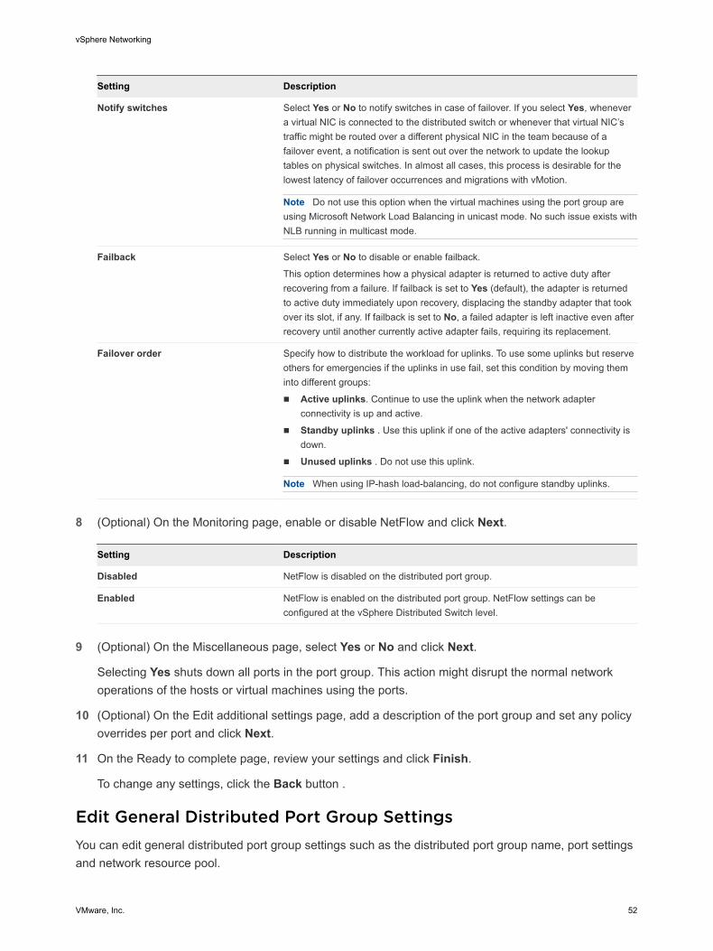
Setting Description
Notify switches Select Yes or No to notify switches in case of failover. If you select Yes, whenever a virtual NIC is connected to the distributed switch or whenever that virtual NIC’s traffic might be routed over a different physical NIC in the team because of a failover event, a notification is sent out over the network to update the lookup tables on physical switches. In almost all cases, this process is desirable for the lowest latency of failover occurrences and migrations with vMotion.
Note Do not use this option when the virtual machines using the port group are using Microsoft Network Load Balancing in unicast mode. No such issue exists with NLB running in multicast mode.
Failback Select Yes or No to disable or enable failback.
This option determines how a physical adapter is returned to active duty after recovering from a failure. If failback is set to Yes (default), the adapter is returned to active duty immediately upon recovery, displacing the standby adapter that took over its slot, if any. If failback is set to No, a failed adapter is left inactive even after recovery until another currently active adapter fails, requiring its replacement.
Failover order Specify how to distribute the workload for uplinks. To use some uplinks but reserve others for emergencies if the uplinks in use fail, set this condition by moving them into different groups:
n Active uplinks. Continue to use the uplink when the network adapter connectivity is up and active.
n Standby uplinks . Use this uplink if one of the active adapters' connectivity is down.
n Unused uplinks . Do not use this uplink.
Note When using IP-hash load-balancing, do not configure standby uplinks.
8 (Optional) On the Monitoring page, enable or disable NetFlow and click Next.
Setting Description
Disabled NetFlow is disabled on the distributed port group.
Enabled NetFlow is enabled on the distributed port group. NetFlow settings can be configured at the vSphere Distributed Switch level.
9 (Optional) On the Miscellaneous page, select Yes or No and click Next.
Selecting Yes shuts down all ports in the port group. This action might disrupt the normal network operations of the hosts or virtual machines using the ports.
10 (Optional) On the Edit additional settings page, add a description of the port group and set any policy overrides per port and click Next.
11 On the Ready to complete page, review your settings and click Finish.
To change any settings, click the Back button .
Edit General Distributed Port Group SettingsYou can edit general distributed port group settings such as the distributed port group name, port settings and network resource pool.
vSphere Networking
VMware, Inc. 52
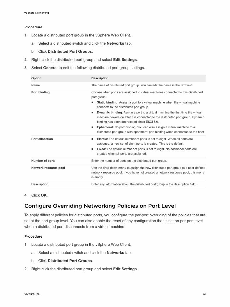
Procedure
1 Locate a distributed port group in the vSphere Web Client.
a Select a distributed switch and click the Networks tab.
b Click Distributed Port Groups.
2 Right-click the distributed port group and select Edit Settings.
3 Select General to edit the following distributed port group settings.
Option Description
Name The name of distributed port group. You can edit the name in the text field.
Port binding Choose when ports are assigned to virtual machines connected to this distributed port group.
n Static binding: Assign a port to a virtual machine when the virtual machine connects to the distributed port group.
n Dynamic binding: Assign a port to a virtual machine the first time the virtual machine powers on after it is connected to the distributed port group. Dynamic binding has been deprecated since ESXi 5.0.
n Ephemeral: No port binding. You can also assign a virtual machine to a distributed port group with ephemeral port binding when connected to the host.
Port allocation n Elastic: The default number of ports is set to eight. When all ports are assigned, a new set of eight ports is created. This is the default.
n Fixed: The default number of ports is set to eight. No additional ports are created when all ports are assigned.
Number of ports Enter the number of ports on the distributed port group.
Network resource pool Use the drop-down menu to assign the new distributed port group to a user-defined network resource pool. If you have not created a network resource pool, this menu is empty.
Description Enter any information about the distributed port group in the description field.
4 Click OK.
Configure Overriding Networking Policies on Port LevelTo apply different policies for distributed ports, you configure the per-port overriding of the policies that are set at the port group level. You can also enable the reset of any configuration that is set on per-port level when a distributed port disconnects from a virtual machine.
Procedure
1 Locate a distributed port group in the vSphere Web Client.
a Select a distributed switch and click the Networks tab.
b Click Distributed Port Groups.
2 Right-click the distributed port group and select Edit Settings.
vSphere Networking
VMware, Inc. 53
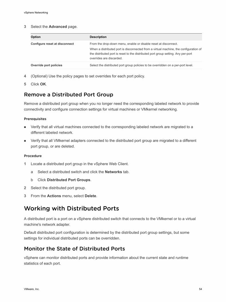
3 Select the Advanced page.
Option Description
Configure reset at disconnect From the drop-down menu, enable or disable reset at disconnect.
When a distributed port is disconnected from a virtual machine, the configuration of the distributed port is reset to the distributed port group setting. Any per-port overrides are discarded.
Override port policies Select the distributed port group policies to be overridden on a per-port level.
4 (Optional) Use the policy pages to set overrides for each port policy.
5 Click OK.
Remove a Distributed Port GroupRemove a distributed port group when you no longer need the corresponding labeled network to provide connectivity and configure connection settings for virtual machines or VMkernel networking.
Prerequisites
n Verify that all virtual machines connected to the corresponding labeled network are migrated to a different labeled network.
n Verify that all VMkernel adapters connected to the distributed port group are migrated to a different port group, or are deleted.
Procedure
1 Locate a distributed port group in the vSphere Web Client.
a Select a distributed switch and click the Networks tab.
b Click Distributed Port Groups.
2 Select the distributed port group.
3 From the Actions menu, select Delete.
Working with Distributed PortsA distributed port is a port on a vSphere distributed switch that connects to the VMkernel or to a virtual machine's network adapter.
Default distributed port configuration is determined by the distributed port group settings, but some settings for individual distributed ports can be overridden.
Monitor the State of Distributed PortsvSphere can monitor distributed ports and provide information about the current state and runtime statistics of each port.
vSphere Networking
VMware, Inc. 54
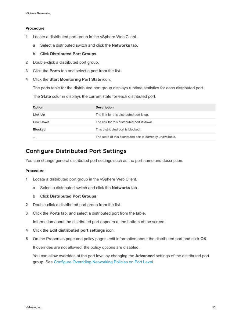
Procedure
1 Locate a distributed port group in the vSphere Web Client.
a Select a distributed switch and click the Networks tab.
b Click Distributed Port Groups.
2 Double-click a distributed port group.
3 Click the Ports tab and select a port from the list.
4 Click the Start Monitoring Port State icon.
The ports table for the distributed port group displays runtime statistics for each distributed port.
The State column displays the current state for each distributed port.
Option Description
Link Up The link for this distributed port is up.
Link Down The link for this distributed port is down.
Blocked This distributed port is blocked.
-- The state of this distributed port is currently unavailable.
Configure Distributed Port SettingsYou can change general distributed port settings such as the port name and description.
Procedure
1 Locate a distributed port group in the vSphere Web Client.
a Select a distributed switch and click the Networks tab.
b Click Distributed Port Groups.
2 Double-click a distributed port group from the list.
3 Click the Ports tab, and select a distributed port from the table.
Information about the distributed port appears at the bottom of the screen.
4 Click the Edit distributed port settings icon.
5 On the Properties page and policy pages, edit information about the distributed port and click OK.
If overrides are not allowed, the policy options are disabled.
You can allow overrides at the port level by changing the Advanced settings of the distributed port group. See Configure Overriding Networking Policies on Port Level.
vSphere Networking
VMware, Inc. 55
Configuring Virtual Machine Networking on a vSphere Distributed SwitchConnect virtual machines to a vSphere distributed switch either by configuring an individual virtual machine NIC or migrating groups of virtual machines from the vSphere distributed switch itself.
Connect virtual machines to vSphere distributed switches by connecting their associated virtual network adapters to distributed port groups. You can do this either for an individual virtual machine by modifying the virtual machine’s network adapter configuration, or for a group of virtual machines by migrating virtual machines from an existing virtual network to a vSphere distributed switch.
Migrate Virtual Machines to or from a vSphere Distributed SwitchIn addition to connecting virtual machines to a distributed switch at the individual virtual machine level, you can migrate a group of virtual machines between a vSphere Distributed Switch network and a vSphere Standard Switch network.
Procedure
1 In the vSphere Web Client, navigate to a data center.
2 Right-click the data center in the navigator and select Migrate VMs to Another Network.
3 Select a source network.
n Select Specific network and use the Browse button to select a specific source network.
n Select No network to migrate all virtual machine network adapters that are not connected to any other network.
4 Use Browse to select a destination network and click Next.
5 Select virtual machines from the list to migrate from the source network to the destination network and click Next.
6 Review your selections and click Finish.
Click Back to edit any selections.
Connect an Individual Virtual Machine to a Distributed Port GroupConnect an individual virtual machine to a vSphere Distributed Switch by modifying the NIC configuration of the virtual machine.
Procedure
1 Locate the virtual machine in the vSphere Web Client.
a Select a data center, folder, cluster, resource pool, or host and click the VMs tab.
b Click Virtual Machines and double-click the virtual machine from the list.
2 On the Configure tab of the virtual machine, expand Settings and select VM Hardware.
3 Click Edit.
vSphere Networking
VMware, Inc. 56

4 Expand the Network adapter section and select Show more networks from the Network adapter drop-down menu.
5 In the Select Network dialog box, select a distributed port group and click OK.
6 Click OK.
Topology Diagrams of a vSphere Distributed Switch in the vSphere Web ClientThe topology diagrams of a vSphere Distributed Switch in the vSphere Web Client show the structure of virtual machine adapters, VMkernel adapters, and physical adapters in the switch.
You can examine the components, arranged in port groups, whose traffic is handled by the switch, and the connections between them. The diagram displays information about the physical adapter that connects the virtual adapters to the external network.
You can view the components that are running on the entire distributed switch and on each host participating in it.
Watch the video about the operations that you can perform from the topology diagram of vSphere Distributed Switch.
Handling Virtual Networking by Using the VDS Topology Diagram (http://link.brightcove.com/services/player/bcpid2296383276001?bctid=ref:video_using_vds_topology_diagram)
Central Topology DiagramYou can use the central topology diagram of the switch to locate and edit the settings for distributed port groups and uplink groups associated with multiple hosts. You can initiate migration of virtual machine adapters from a port group to a destination on the same or different switch. You can also reorganize the hosts and their networking on the switch by using the Add and Manage Hosts wizard.
Topology Diagram of a Host Proxy SwitchThe topology diagram of a host proxy switch shows the adapters attached to the switch ports on the host. You can edit the settings of the VMkernel and physical adapters.
Diagram FiltersYou can use diagram filters to limit the information displayed in topology diagrams. The default filter limits the topology diagram to display 32 port groups, 32 hosts, and 1024 virtual machines.
You can change the scope of the diagram by using no filters or by applying custom filters. By using a custom filter, you can view information only about a set of virtual machines, a set of port groups on certain hosts, or a port. You can create filters from the central topology diagram of the distributed switch.
vSphere Networking
VMware, Inc. 57
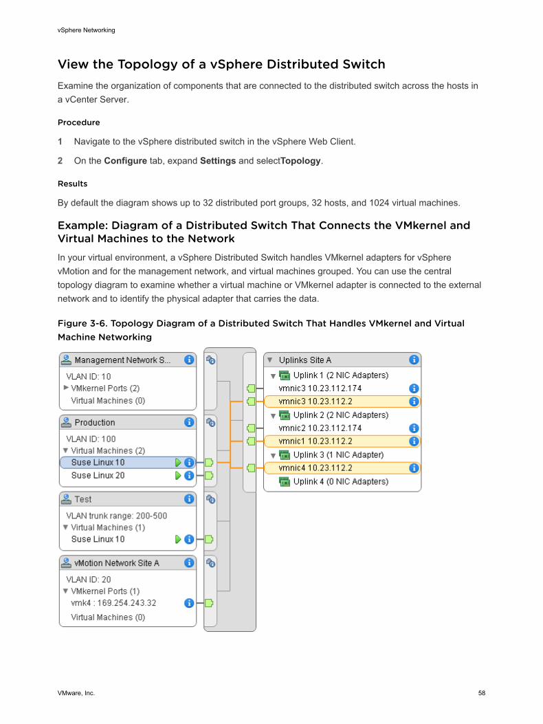
View the Topology of a vSphere Distributed SwitchExamine the organization of components that are connected to the distributed switch across the hosts in a vCenter Server.
Procedure
1 Navigate to the vSphere distributed switch in the vSphere Web Client.
2 On the Configure tab, expand Settings and selectTopology.
Results
By default the diagram shows up to 32 distributed port groups, 32 hosts, and 1024 virtual machines.
Example: Diagram of a Distributed Switch That Connects the VMkernel and Virtual Machines to the NetworkIn your virtual environment, a vSphere Distributed Switch handles VMkernel adapters for vSphere vMotion and for the management network, and virtual machines grouped. You can use the central topology diagram to examine whether a virtual machine or VMkernel adapter is connected to the external network and to identify the physical adapter that carries the data.
Figure 3-6. Topology Diagram of a Distributed Switch That Handles VMkernel and Virtual Machine Networking
vSphere Networking
VMware, Inc. 58
What to do next
You can perform the following common tasks in the topology of the distributed switch:
n Use filters to view the networking components only for selected port groups on certain hosts, for selected virtual machines, or for a port.
n Locate, configure and migrate virtual machine networking components across host and port groups by using the Migrate Virtual Machine Networking wizard.
n Detect the virtual machine adapters that have no network assigned and move them to the selected port group by using the Migrate Virtual Machine Networking wizard.
n Handle networking components on multiple hosts by using the Add and Manage Hosts wizard.
n View the physical NIC or NIC team that carries the traffic related to a selected virtual machine adapter or VMkernel adapter.
In this way you can also view the host on which a selected VMkernel adapter resides. Select the adapter, trace the route to the associated physical NIC, and view the IP address or domain name next to the NIC.
n Determine the VLAN mode and ID for a port group. For information about VLAN modes, see VLAN Configuration.
View the Topology of a Host Proxy SwitchExamine and reorganize the networking of the VMkernel and virtual machines that the vSphere Distributed Switch handles on a host.
Procedure
1 In the vSphere Web Client, navigate to the host.
2 On the Configure tab, expand Networking and select Virtual switches.
3 Select the distributed switch from the list.
Results
The topology of the host proxy switch appears under the list.
vSphere Networking
VMware, Inc. 59
Setting Up VMkernel Networking 4You set up VMkernel adapters to provide network connectivity to hosts and to accommodate system traffic of vMotion, IP storage, Fault Tolerance logging, vSAN, and so on.
n VMkernel Networking Layer
The VMkernel networking layer provides connectivity to hosts and handles the standard system traffic of vSphere vMotion, IP storage, Fault Tolerance, vSAN, and others. You can also create VMkernel adapters on the source and target vSphere Replication hosts to isolate the replication data traffic.
n View Information About VMkernel Adapters on a Host
You can view each VMkernel adapter's assigned services, associated switch, port settings, IP settings, TCP/IP stack, VLAN ID, and policies.
n Create a VMkernel Adapter on a vSphere Standard Switch
Create a VMkernel network adapter on a vSphere standard switch to provide network connectivity for hosts and to handle the system traffic for vSphere vMotion, IP storage, Fault Tolerance logging, vSAN, and so on. You can also create VMkernel adapters on the source and target vSphere Replication hosts to isolate the replication data traffic. Dedicate a VMkernel adapter to only one traffic type.
n Create a VMkernel Adapter on a Host Associated with a vSphere Distributed Switch
Create a VMkernel adapter on a host that is associated with a distributed switch to provide network connectivity to the host and to handle the traffic for vSphere vMotion, IP storage, Fault Tolerance logging, vSAN, and others. You can set up VMkernel adapters for the standard system traffic on vSphere standard switches and on vSphere distributed switches.
n Edit a VMkernel Adapter Configuration
You might have to change the supported traffic type for a VMkernel adapter, or the way IPv4 or IPv6 addresses are obtained.
n Overriding the Default Gateway of a VMkernel Adapter
You might need to override the default gateway for a VMkernel adapter to provide a different gateway for vSphere vMotion.
VMware, Inc. 60
n Configure the VMkernel Adapter Gateway by Using esxcli Commands
You can override the default gateway of a VMkernel adapter to provide a different gateway for vSphere vMotion by using esxcli commands.
n View TCP/IP Stack Configuration on a Host
You can view the DNS and routing configuration of a TCP/IP stack on a host. You can also view the IPv4 and IPv6 routing tables, the congestion control algorithm, and the maximum number of allowed connections.
n Change the Configuration of a TCP/IP Stack on a Host
You can change the DNS and default gateway configuration of a TCP/IP stack on a host. You can also change the congestion control algorithm, the maximum number of connections, and the name of custom TCP/IP stacks.
n Create a Custom TCP/IP Stack
You can create a custom TCP/IP stack on a host to forward networking traffic through a custom application.
n Remove a VMkernel Adapter
Remove a VMkernel adapter from a vSphere distributed or a standard switch when you no longer need the adapter. Make sure that you leave at least one VMkernel adapter for management traffic on the host to keep the network connectivity up.
VMkernel Networking LayerThe VMkernel networking layer provides connectivity to hosts and handles the standard system traffic of vSphere vMotion, IP storage, Fault Tolerance, vSAN, and others. You can also create VMkernel adapters on the source and target vSphere Replication hosts to isolate the replication data traffic.
TCP/IP Stacks at the VMkernel Level
Default TCP/IP stack Provides networking support for the management traffic between vCenter Server and ESXi hosts, and for system traffic such as vMotion, IP storage, Fault Tolerance, and so on.
vMotion TCP/IP stack Supports the traffic for live migration of virtual machines. Use the vMotion TCP/IP to provide better isolation for the vMotion traffic. After you create a VMkernel adapter on the vMotion TCP/IP stack, you can use only this stack for vMotion on this host. The VMkernel adapters on the default TCP/IP stack are disabled for the vMotion service. If a live migration uses the default TCP/IP stack while you configure VMkernel adapters with the vMotion TCP/IP stack, the migration completes successfully. However, the involved VMkernel adapters on the default TCP/IP stack are disabled for future vMotion sessions.
Provisioning TCP/IP stack
Supports the traffic for virtual machine cold migration, cloning, and snapshot migration. You can use the provisioning TCP/IP to handle
vSphere Networking
VMware, Inc. 61
Network File Copy (NFC) traffic during long-distance vMotion. NFC provides a file-specific FTP service for vSphere. ESXi uses NFC for copying and moving data between datastores. VMkernel adapters configured with the provisioning TCP/IP stack handle the traffic from cloning the virtual disks of the migrated virtual machines in long-distance vMotion. By using the provisioning TCP/IP stack, you can isolate the traffic from the cloning operations on a separate gateway. After you configure a VMkernel adapter with the provisioning TCP/IP stack, all adapters on the default TCP/IP stack are disabled for the Provisioning traffic.
Custom TCP/IP stacks You can add custom TCP/IP stacks at the VMkernel level to handle networking traffic of custom applications.
Securing System TrafficTake appropriate security measures to prevent unauthorized access to the management and system traffic in your vSphere environment. For example, isolate the vMotion traffic in a separate network that includes only the ESXi hosts that participate in the migration. Isolate the management traffic in a network that only network and security administrators can access. For more information, see vSphere Security and vSphere Installation and Setup.
System Traffic TypesDedicate a separate VMkernel adapter for every traffic type . For distributed switches, dedicate a separate distributed port group for each VMkernel adapter.
Management traffic Carries the configuration and management communication for ESXi hosts, vCenter Server, and host-to-host High Availability traffic. By default, when you install the ESXi software, a vSphere Standard switch is created on the host together with a VMkernel adapter for management traffic. To provide redundancy, you can connect two or more physical NICs to a VMkernel adapter for management traffic.
vMotion traffic Accommodates vMotion. A VMkernel adapter for vMotion is required both on the source and the target hosts. Configure The VMkernel adapters for vMotion to handle only the vMotion traffic. For better performance, you can configure multiple NIC vMotion. To have multi-NIC vMotion, you can dedicate two or more port groups to the vMotion traffic, respectively every port group must have a vMotion VMkernel adapter associated with it. Then you can connect one or more physical NICs to every port group. In this way, multiple physical NICs are used for vMotion, which results in greater bandwidth .
Note vMotion network traffic is not encrypted. You should provision secure private networks for use by vMotion only.
vSphere Networking
VMware, Inc. 62
Provisioning traffic Handles the data that is transferred for virtual machine cold migration, cloning, and snapshot migration.
IP storage traffic and discovery
Handles the connection for storage types that use standard TCP/IP networks and depend on the VMkernel networking. Such storage types are software iSCSI, dependent hardware iSCSI, and NFS. If you have two or more physical NICs for iSCSI, you can configure iSCSI multipathing. ESXi hosts support NFS 3 and 4.1. To configure a software Fibre Channel over Ethernet (FCoE) adapter, you must have a dedicated VMkernel adapter. Software FCoE passes configuration information though the Data Center Bridging Exchange (DCBX) protocol by using the Cisco Discovery Protocol (CDP )VMkernel module.
Fault Tolerance traffic Handles the data that the primary fault tolerant virtual machine sends to the secondary fault tolerant virtual machine over the VMkernel networking layer. A separate VMkernel adapter for Fault Tolerance logging is required on every host that is part of a vSphere HA cluster.
vSphere Replication traffic
Handles the outgoing replication data that the source ESXi host transfers to the vSphere Replication server. Dedicate a VMkernel adapter on the source site to isolate the outgoing replication traffic.
vSphere Replication NFC traffic
Handles the incoming replication data on the target replication site.
vSAN traffic Every host that participates in a vSAN cluster must have a VMkernel adapter to handle the vSAN traffic.
View Information About VMkernel Adapters on a HostYou can view each VMkernel adapter's assigned services, associated switch, port settings, IP settings, TCP/IP stack, VLAN ID, and policies.
Procedure
1 In the vSphere Web Client, navigate to the host.
2 Click the Configure tab and expand the Networking menu.
3 To view information about all VMkernel adapters on the host, select VMkernel adapters.
4 Select an adapter from the VMkernel adapters list to view its settings.
Tab Description
All Displays all configuration information about the VMkernel adapter. This information includes port and NIC settings, IPv4 and IPv6 settings, traffic shaping, teaming and failover, and security policies.
Properties Displays the port properties and NIC settings of the VMkernel adapter. The port properties include the port group (network label) to which the adapter is associated, the VLAN ID, and the enabled services. The NIC settings include MAC address and the configured MTU size.
vSphere Networking
VMware, Inc. 63
Tab Description
IP Settings Displays all IPv4 and IPv6 settings for the VMkernel adapter. IPv6 information is not displayed if IPv6 has not been enabled on the host.
Policies Displays the configured traffic shaping, teaming and failover, and security policies that apply for the port group to which the VMkernel adapter is connected.
Create a VMkernel Adapter on a vSphere Standard SwitchCreate a VMkernel network adapter on a vSphere standard switch to provide network connectivity for hosts and to handle the system traffic for vSphere vMotion, IP storage, Fault Tolerance logging, vSAN, and so on. You can also create VMkernel adapters on the source and target vSphere Replication hosts to isolate the replication data traffic. Dedicate a VMkernel adapter to only one traffic type.
Procedure
1 In the vSphere Web Client, navigate to the host.
2 On the Configure tab, expand Networking and select VMkernel adapters.
3 Click Add host networking.
4 On the Select connection type page, select VMkernel Network Adapter and click Next.
5 On the Select target device page, select either an existing standard switch or select New standard switch.
6 (Optional) On the Create a Standard Switch page, assign physical NICs to the switch.
You can create the standard switch without physical NICs and configure them later. During the time that no physical NICs are attached to the host, the host does not have network connectivity to the other hosts on the physical network. The virtual machines on the host are able to communicate with each other.
a Click Add adapters and select as many physical NICs as you need.
b Use the up and down arrows to configure the active and standby NICs.
7 On the Port properties page, configure the settings for the VMkernel adapter.
Option Description
Network label Type a value for this label to indicate the traffic type for the VMkernel adapter, for example Management traffic or vMotion.
VLAN ID Set a VLAN ID to identify the VLAN that the network traffic of the VMkernel adapter will use.
IP settings Select IPv4, IPv6, or both.
Note The IPv6 option does not appear on hosts that do not have IPv6 enabled.
vSphere Networking
VMware, Inc. 64
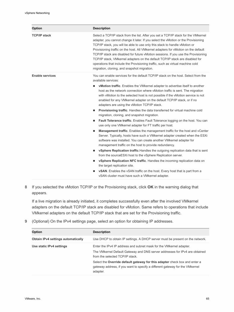
Option Description
TCP/IP stack Select a TCP/IP stack from the list. After you set a TCP/IP stack for the VMkernel adapter, you cannot change it later. If you select the vMotion or the Provisioning TCP/IP stack, you will be able to use only this stack to handle vMotion or Provisioning traffic on the host. All VMkernel adapters for vMotion on the default TCP/IP stack are disabled for future vMotion sessions. If you use the Provisioning TCP/IP stack, VMkernel adapters on the default TCP/IP stack are disabled for operations that include the Provisioning traffic, such as virtual machine cold migration, cloning, and snapshot migration.
Enable services You can enable services for the default TCP/IP stack on the host. Select from the available services:
n vMotion traffic. Enables the VMkernel adapter to advertise itself to another host as the network connection where vMotion traffic is sent. The migration with vMotion to the selected host is not possible if the vMotion service is not enabled for any VMkernel adapter on the default TCP/IP stack, or if no adapters are using the vMotion TCP/IP stack.
n Provisioning traffic. Handles the data transferred for virtual machine cold migration, cloning, and snapshot migration.
n Fault Tolerance traffic. Enables Fault Tolerance logging on the host. You can use only one VMkernel adapter for FT traffic per host.
n Management traffic. Enables the management traffic for the host and vCenter Server. Typically, hosts have such a VMkernel adapter created when the ESXi software was installed. You can create another VMkernel adapter for management traffic on the host to provide redundancy.
n vSphere Replication traffic.Handles the outgoing replication data that is sent from the sourceESXi host to the vSphere Replication server.
n vSphere Replication NFC traffic. Handles the incoming replication data on the target replication site.
n vSAN. Enables the vSAN traffic on the host. Every host that is part from a vSAN cluster must have such a VMkernel adapter.
8 If you selected the vMotion TCP/IP or the Provisioning stack, click OK in the warning dialog that
appears.
If a live migration is already initiated, it completes successfully even after the involved VMkernel adapters on the default TCP/IP stack are disabled for vMotion. Same refers to operations that include VMkernel adapters on the default TCP/IP stack that are set for the Provisioning traffic.
9 (Optional) On the IPv4 settings page, select an option for obtaining IP addresses.
Option Description
Obtain IPv4 settings automatically Use DHCP to obtain IP settings. A DHCP server must be present on the network.
Use static IPv4 settings Enter the IPv4 IP address and subnet mask for the VMkernel adapter.
The VMkernel Default Gateway and DNS server addresses for IPv4 are obtained from the selected TCP/IP stack.
Select the Override default gateway for this adapter check box and enter a gateway address, if you want to specify a different gateway for the VMkernel adapter.
vSphere Networking
VMware, Inc. 65
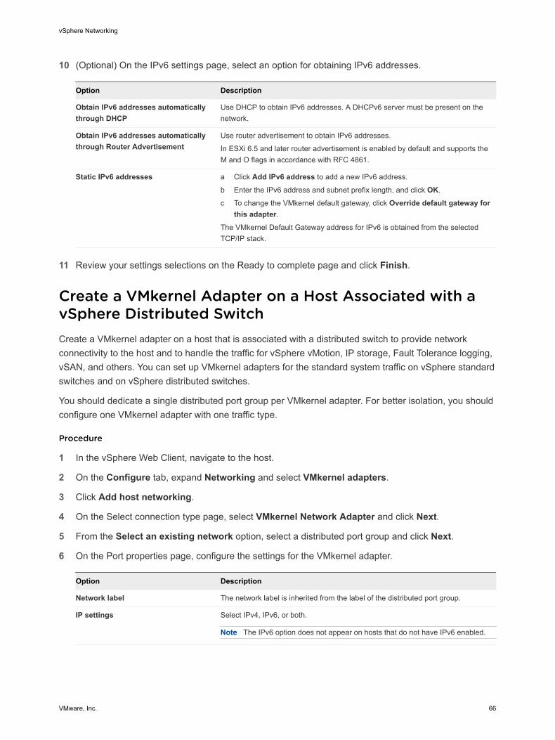
10 (Optional) On the IPv6 settings page, select an option for obtaining IPv6 addresses.
Option Description
Obtain IPv6 addresses automatically through DHCP
Use DHCP to obtain IPv6 addresses. A DHCPv6 server must be present on the network.
Obtain IPv6 addresses automatically through Router Advertisement
Use router advertisement to obtain IPv6 addresses.
In ESXi 6.5 and later router advertisement is enabled by default and supports the M and O flags in accordance with RFC 4861.
Static IPv6 addresses a Click Add IPv6 address to add a new IPv6 address.
b Enter the IPv6 address and subnet prefix length, and click OK.
c To change the VMkernel default gateway, click Override default gateway for this adapter.
The VMkernel Default Gateway address for IPv6 is obtained from the selected TCP/IP stack.
11 Review your settings selections on the Ready to complete page and click Finish.
Create a VMkernel Adapter on a Host Associated with a vSphere Distributed SwitchCreate a VMkernel adapter on a host that is associated with a distributed switch to provide network connectivity to the host and to handle the traffic for vSphere vMotion, IP storage, Fault Tolerance logging, vSAN, and others. You can set up VMkernel adapters for the standard system traffic on vSphere standard switches and on vSphere distributed switches.
You should dedicate a single distributed port group per VMkernel adapter. For better isolation, you should configure one VMkernel adapter with one traffic type.
Procedure
1 In the vSphere Web Client, navigate to the host.
2 On the Configure tab, expand Networking and select VMkernel adapters.
3 Click Add host networking.
4 On the Select connection type page, select VMkernel Network Adapter and click Next.
5 From the Select an existing network option, select a distributed port group and click Next.
6 On the Port properties page, configure the settings for the VMkernel adapter.
Option Description
Network label The network label is inherited from the label of the distributed port group.
IP settings Select IPv4, IPv6, or both.
Note The IPv6 option does not appear on hosts that do not have IPv6 enabled.
vSphere Networking
VMware, Inc. 66

Option Description
TCP/IP stack Select a TCP/IP stack from the list. Once you set a TCP/IP stack for the VMkernel adapter, you cannot change it later. If you select the vMotion or the Provisioning TCP/IP stack, you will be able to use only these stacks to handle vMotion or Provisioning traffic on the host. All VMkernel adapters for vMotion on the default TCP/IP stack are disabled for future vMotion sessions. If you set the Provisioning TCP/IP stack, VMkernel adapters on the default TCP/IP stack are disabled for operations that include Provisioning traffic, such as virtual machine cold migration, cloning, and snapshot migration.
Enable services You can enable services for the default TCP/IP stack on the host. Select from the available services:
n vMotion traffic. Enables the VMkernel adapter to advertise itself to another host as the network connection where vMotion traffic is sent. The migration with vMotion to the selected host is not possible if the vMotion service is not enabled for any VMkernel adapter on the default TCP/IP stack, or there are no adapters using the vMotion TCP/IP stack.
n Provisioning traffic. Handles the data transferred for virtual machine cold migration, cloning, and snapshot migration.
n Fault Tolerance traffic. Enables Fault Tolerance logging on the host. You can use only one VMkernel adapter for FT traffic per host.
n Management traffic. Enables the management traffic for the host and vCenter Server. Typically, hosts have such a VMkernel adapter created when the ESXi software is installed. You can create another VMkernel adapter for management traffic on the host to provide redundancy.
n vSphere Replication traffic. Handles the outgoing replication data that is sent from the source ESXi host to the vSphere Replication server.
n vSphere Replication NFC traffic. Handles the incoming replication data on the target replication site.
n vSAN. Enables thevSAN traffic on the host. Every host that is part of a vSAN cluster must have such a VMkernel adapter.
7 If you selected the vMotion TCP/IP or the Provisioning stack, click OK in the warning dialog that
appears.
If a live migration is already initiated, it completes successfully even after the involved VMkernel adapters on the default TCP/IP stack are disabled for vMotion. Same refers to operations that include VMkernel adapters on the default TCP/IP stack that are set for the Provisioning traffic.
8 (Optional) On the IPv4 settings page, select an option for obtaining IP addresses.
Option Description
Obtain IPv4 settings automatically Use DHCP to obtain IP settings. A DHCP server must be present on the network.
Use static IPv4 settings Enter the IPv4 IP address and subnet mask for the VMkernel adapter.
The VMkernel Default Gateway and DNS server addresses for IPv4 are obtained from the selected TCP/IP stack.
Select the Override default gateway for this adapter check box and enter a gateway address, if you want to specify a different gateway for the VMkernel adapter.
vSphere Networking
VMware, Inc. 67
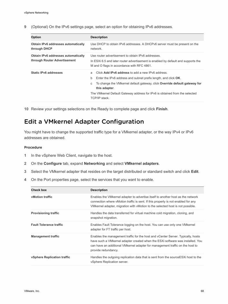
9 (Optional) On the IPv6 settings page, select an option for obtaining IPv6 addresses.
Option Description
Obtain IPv6 addresses automatically through DHCP
Use DHCP to obtain IPv6 addresses. A DHCPv6 server must be present on the network.
Obtain IPv6 addresses automatically through Router Advertisement
Use router advertisement to obtain IPv6 addresses.
In ESXi 6.5 and later router advertisement is enabled by default and supports the M and O flags in accordance with RFC 4861.
Static IPv6 addresses a Click Add IPv6 address to add a new IPv6 address.
b Enter the IPv6 address and subnet prefix length, and click OK.
c To change the VMkernel default gateway, click Override default gateway for this adapter.
The VMkernel Default Gateway address for IPv6 is obtained from the selected TCP/IP stack.
10 Review your settings selections on the Ready to complete page and click Finish.
Edit a VMkernel Adapter ConfigurationYou might have to change the supported traffic type for a VMkernel adapter, or the way IPv4 or IPv6 addresses are obtained.
Procedure
1 In the vSphere Web Client, navigate to the host.
2 On the Configure tab, expand Networking and select VMkernel adapters.
3 Select the VMkernel adapter that resides on the target distributed or standard switch and click Edit.
4 On the Port properties page, select the services that you want to enable.
Check box Description
vMotion traffic Enables the VMkernel adapter to advertise itself to another host as the network connection where vMotion traffic is sent. If this property is not enabled for any VMkernel adapter, migration with vMotion to the selected host is not possible.
Provisioning traffic Handles the data transferred for virtual machine cold migration, cloning, and snapshot migration.
Fault Tolerance traffic Enables Fault Tolerance logging on the host. You can use only one VMkernel adapter for FT traffic per host.
Management traffic Enables the management traffic for the host and vCenter Server. Typically, hosts have such a VMkernel adapter created when the ESXi software was installed. You can have an additional VMkernel adapter for management traffic on the host to provide redundancy.
vSphere Replication traffic Handles the outgoing replication data that is sent from the sourceESXi host to the vSphere Replication server.
vSphere Networking
VMware, Inc. 68
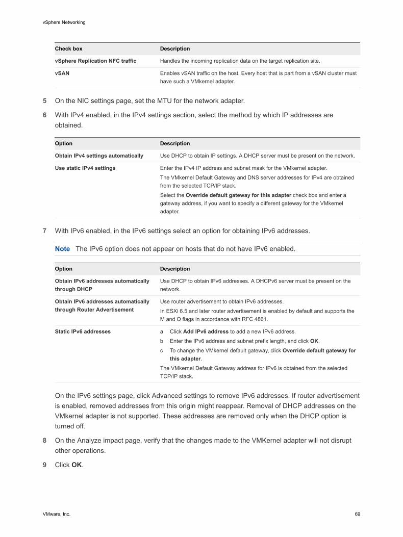
Check box Description
vSphere Replication NFC traffic Handles the incoming replication data on the target replication site.
vSAN Enables vSAN traffic on the host. Every host that is part from a vSAN cluster must have such a VMkernel adapter.
5 On the NIC settings page, set the MTU for the network adapter.
6 With IPv4 enabled, in the IPv4 settings section, select the method by which IP addresses are obtained.
Option Description
Obtain IPv4 settings automatically Use DHCP to obtain IP settings. A DHCP server must be present on the network.
Use static IPv4 settings Enter the IPv4 IP address and subnet mask for the VMkernel adapter.
The VMkernel Default Gateway and DNS server addresses for IPv4 are obtained from the selected TCP/IP stack.
Select the Override default gateway for this adapter check box and enter a gateway address, if you want to specify a different gateway for the VMkernel adapter.
7 With IPv6 enabled, in the IPv6 settings select an option for obtaining IPv6 addresses.
Note The IPv6 option does not appear on hosts that do not have IPv6 enabled.
Option Description
Obtain IPv6 addresses automatically through DHCP
Use DHCP to obtain IPv6 addresses. A DHCPv6 server must be present on the network.
Obtain IPv6 addresses automatically through Router Advertisement
Use router advertisement to obtain IPv6 addresses.
In ESXi 6.5 and later router advertisement is enabled by default and supports the M and O flags in accordance with RFC 4861.
Static IPv6 addresses a Click Add IPv6 address to add a new IPv6 address.
b Enter the IPv6 address and subnet prefix length, and click OK.
c To change the VMkernel default gateway, click Override default gateway for this adapter.
The VMkernel Default Gateway address for IPv6 is obtained from the selected TCP/IP stack.
On the IPv6 settings page, click Advanced settings to remove IPv6 addresses. If router advertisement is enabled, removed addresses from this origin might reappear. Removal of DHCP addresses on the VMkernel adapter is not supported. These addresses are removed only when the DHCP option is turned off.
8 On the Analyze impact page, verify that the changes made to the VMKernel adapter will not disrupt other operations.
9 Click OK.
vSphere Networking
VMware, Inc. 69
Overriding the Default Gateway of a VMkernel AdapterYou might need to override the default gateway for a VMkernel adapter to provide a different gateway for vSphere vMotion.
Each TCP/IP stack on a host can have only one default gateway. This default gateway is part of the routing table and all services that operate on the TCP/IP stack use it.
For example, the VMkernel adapters vmk0 and vmk1 can be configured on a host.
n vmk0 is used for management traffic on the 10.162.10.0/24 subnet, with default gateway 10.162.10.1
n vmk1 is used for vMotion traffic on the 172.16.1.0/24 subnet
If you set 172.16.1.1 as the default gateway for vmk1, vMotion uses vmk1 as its egress interface with the gateway 172.16.1.1. The 172.16.1.1 gateway is a part of the vmk1 configuration and is not in the routing table. Only the services that specify vmk1 as an egress interface use this gateway. This provides additional Layer 3 connectivity options for services that need multiple gateways.
You can use the vSphere Web Client or an ESXCLI command to configure the default gateway of a VMkernel adapter.
See Create a VMkernel Adapter on a vSphere Standard Switch, Create a VMkernel Adapter on a Host Associated with a vSphere Distributed Switch, and Configure the VMkernel Adapter Gateway by Using esxcli Commands.
Configure the VMkernel Adapter Gateway by Using esxcli CommandsYou can override the default gateway of a VMkernel adapter to provide a different gateway for vSphere vMotion by using esxcli commands.
Procedure
1 Open an SSH connection to the host.
2 Log in as the root user.
vSphere Networking
VMware, Inc. 70
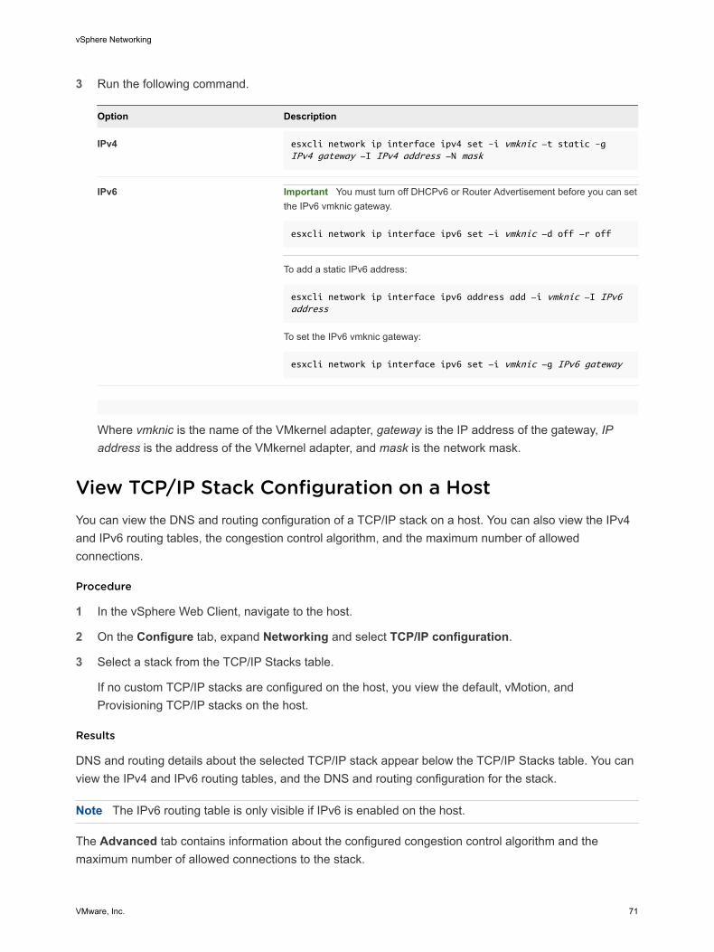
3 Run the following command.
Option Description
IPv4 esxcli network ip interface ipv4 set –i vmknic -t static –g IPv4 gateway -I IPv4 address -N mask
IPv6 Important You must turn off DHCPv6 or Router Advertisement before you can set the IPv6 vmknic gateway.
esxcli network ip interface ipv6 set -i vmknic -d off -r off
To add a static IPv6 address:
esxcli network ip interface ipv6 address add -i vmknic -I IPv6 address
To set the IPv6 vmknic gateway:
esxcli network ip interface ipv6 set -i vmknic -g IPv6 gateway
Where vmknic is the name of the VMkernel adapter, gateway is the IP address of the gateway, IP address is the address of the VMkernel adapter, and mask is the network mask.
View TCP/IP Stack Configuration on a HostYou can view the DNS and routing configuration of a TCP/IP stack on a host. You can also view the IPv4 and IPv6 routing tables, the congestion control algorithm, and the maximum number of allowed connections.
Procedure
1 In the vSphere Web Client, navigate to the host.
2 On the Configure tab, expand Networking and select TCP/IP configuration.
3 Select a stack from the TCP/IP Stacks table.
If no custom TCP/IP stacks are configured on the host, you view the default, vMotion, and Provisioning TCP/IP stacks on the host.
Results
DNS and routing details about the selected TCP/IP stack appear below the TCP/IP Stacks table. You can view the IPv4 and IPv6 routing tables, and the DNS and routing configuration for the stack.
Note The IPv6 routing table is only visible if IPv6 is enabled on the host.
The Advanced tab contains information about the configured congestion control algorithm and the maximum number of allowed connections to the stack.
vSphere Networking
VMware, Inc. 71
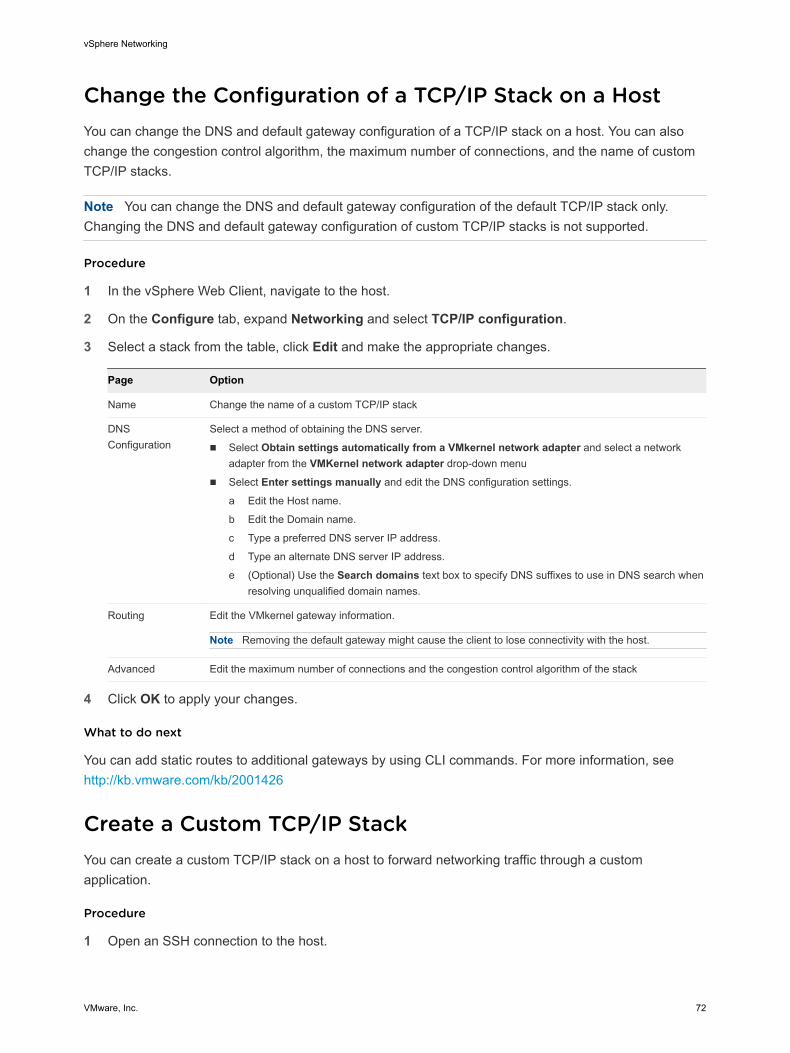
Change the Configuration of a TCP/IP Stack on a HostYou can change the DNS and default gateway configuration of a TCP/IP stack on a host. You can also change the congestion control algorithm, the maximum number of connections, and the name of custom TCP/IP stacks.
Note You can change the DNS and default gateway configuration of the default TCP/IP stack only. Changing the DNS and default gateway configuration of custom TCP/IP stacks is not supported.
Procedure
1 In the vSphere Web Client, navigate to the host.
2 On the Configure tab, expand Networking and select TCP/IP configuration.
3 Select a stack from the table, click Edit and make the appropriate changes.
Page Option
Name Change the name of a custom TCP/IP stack
DNS Configuration
Select a method of obtaining the DNS server.
n Select Obtain settings automatically from a VMkernel network adapter and select a network adapter from the VMKernel network adapter drop-down menu
n Select Enter settings manually and edit the DNS configuration settings.
a Edit the Host name.
b Edit the Domain name.
c Type a preferred DNS server IP address.
d Type an alternate DNS server IP address.
e (Optional) Use the Search domains text box to specify DNS suffixes to use in DNS search when resolving unqualified domain names.
Routing Edit the VMkernel gateway information.
Note Removing the default gateway might cause the client to lose connectivity with the host.
Advanced Edit the maximum number of connections and the congestion control algorithm of the stack
4 Click OK to apply your changes.
What to do next
You can add static routes to additional gateways by using CLI commands. For more information, see http://kb.vmware.com/kb/2001426
Create a Custom TCP/IP StackYou can create a custom TCP/IP stack on a host to forward networking traffic through a custom application.
Procedure
1 Open an SSH connection to the host.
vSphere Networking
VMware, Inc. 72
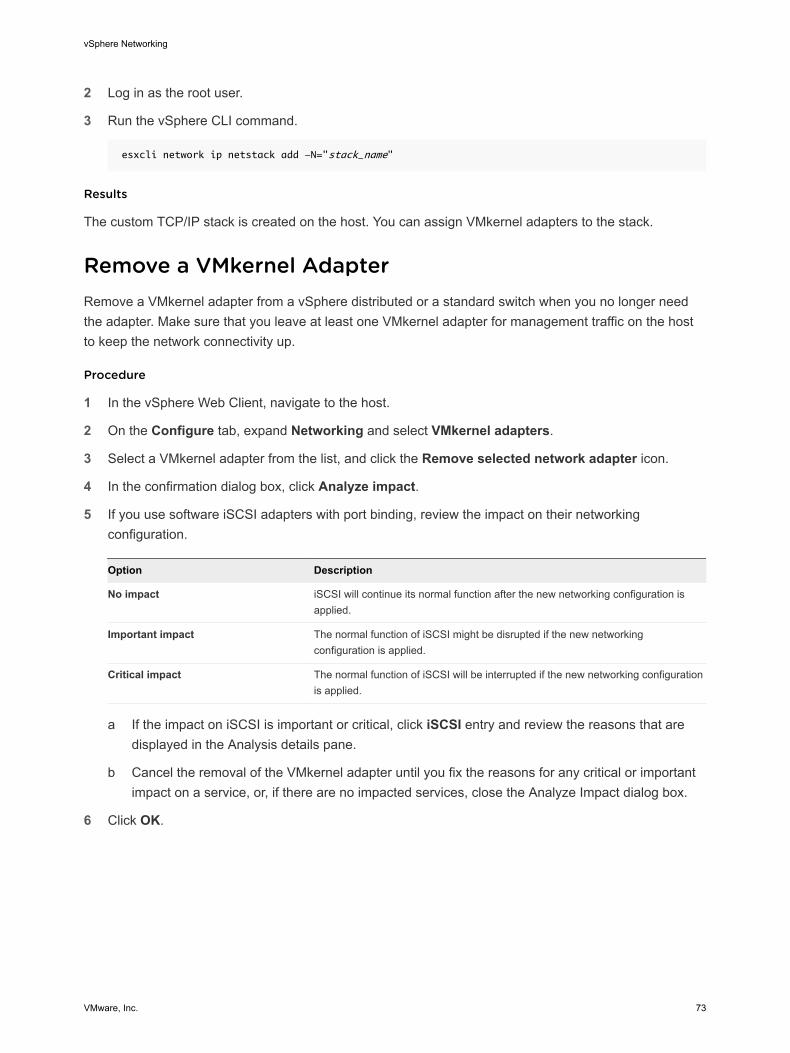
2 Log in as the root user.
3 Run the vSphere CLI command.
esxcli network ip netstack add -N="stack_name"
Results
The custom TCP/IP stack is created on the host. You can assign VMkernel adapters to the stack.
Remove a VMkernel AdapterRemove a VMkernel adapter from a vSphere distributed or a standard switch when you no longer need the adapter. Make sure that you leave at least one VMkernel adapter for management traffic on the host to keep the network connectivity up.
Procedure
1 In the vSphere Web Client, navigate to the host.
2 On the Configure tab, expand Networking and select VMkernel adapters.
3 Select a VMkernel adapter from the list, and click the Remove selected network adapter icon.
4 In the confirmation dialog box, click Analyze impact.
5 If you use software iSCSI adapters with port binding, review the impact on their networking configuration.
Option Description
No impact iSCSI will continue its normal function after the new networking configuration is applied.
Important impact The normal function of iSCSI might be disrupted if the new networking configuration is applied.
Critical impact The normal function of iSCSI will be interrupted if the new networking configuration is applied.
a If the impact on iSCSI is important or critical, click iSCSI entry and review the reasons that are
displayed in the Analysis details pane.
b Cancel the removal of the VMkernel adapter until you fix the reasons for any critical or important impact on a service, or, if there are no impacted services, close the Analyze Impact dialog box.
6 Click OK.
vSphere Networking
VMware, Inc. 73
LACP Support on a vSphere Distributed Switch 5With LACP support on a vSphere Distributed Switch, you can connect ESXi hosts to physical switches by using dynamic link aggregation. You can create multiple link aggregation groups (LAGs) on a distributed switch to aggregate the bandwidth of physical NICs on ESXi hosts that are connected to LACP port channels.
VMware, Inc. 74
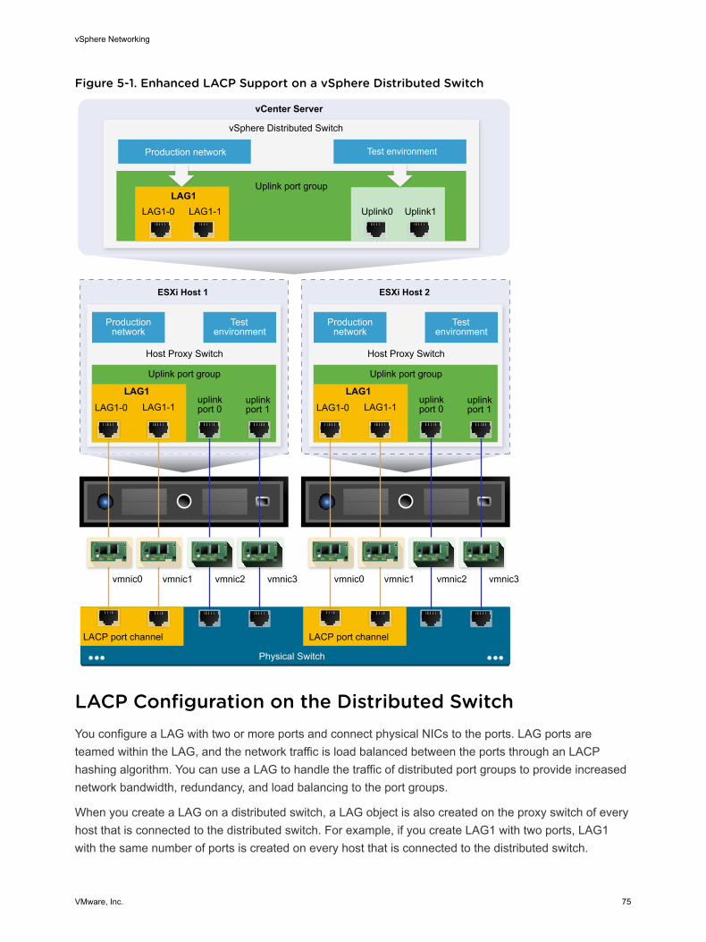
Figure 5-1. Enhanced LACP Support on a vSphere Distributed Switch
Physical Switch
Uplink port group
Uplink0
ESXi Host 1
Uplink port group
vSphere Distributed Switch
vCenter Server
Host Proxy Switch
Production network
Test environment
Uplink1
uplinkport 0
uplinkport 1
Production network Test environment
Uplink port group
ESXi Host 2
Host Proxy Switch
Production network
Test environment
uplinkport 0
uplinkport 1
vmnic0 vmnic1 vmnic2 vmnic3
LAG1-0 LAG1-1LAG1
LACP port channel
vmnic0 vmnic1 vmnic2 vmnic3
LAG1-0 LAG1-1LAG1
LAG1-0 LAG1-1LAG1
LACP port channel
LACP Configuration on the Distributed SwitchYou configure a LAG with two or more ports and connect physical NICs to the ports. LAG ports are teamed within the LAG, and the network traffic is load balanced between the ports through an LACP hashing algorithm. You can use a LAG to handle the traffic of distributed port groups to provide increased network bandwidth, redundancy, and load balancing to the port groups.
When you create a LAG on a distributed switch, a LAG object is also created on the proxy switch of every host that is connected to the distributed switch. For example, if you create LAG1 with two ports, LAG1 with the same number of ports is created on every host that is connected to the distributed switch.
vSphere Networking
VMware, Inc. 75
On a host proxy switch, you can connect one physical NIC to only one LAG port. On the distributed switch, one LAG port can have multiple physical NICs from different hosts connected to it. The physical NICs on a host that you connect to the LAG ports must be connected to links that participate in an LACP port channel on the physical switch.
You can create up to 64 LAGs on a distributed switch. A host can support up to 32 LAGs. However, the number of LAGs that you can actually use depends on the capabilities of the underlying physical environment and the topology of the virtual network. For example, if the physical switch supports up to four ports in an LACP port channel, you can connect up to four physical NICs per host to a LAG.
Port Channel Configuration on the Physical SwitchFor each host on which you want to use LACP, you must create a separate LACP port channel on the physical switch. You must consider the following requirements when configuring LACP on the physical switch:
n The number of ports in the LACP port channel must be equal to the number of physical NICs that you want to group on the host. For example, if you want to aggregate the bandwidth of two physical NICs on a host, you must create an LACP port channel with two ports on the physical switch. The LAG on the distributed switch must be configured with at least two ports.
n The hashing algorithm of the LACP port channel on the physical switch must be the same as the hashing algorithm that is configured to the LAG on the distributed switch.
n All physical NICs that you want to connect to the LACP port channel must be configured with the same speed and duplex.
This chapter includes the following topics:
n LACP Teaming and Failover Configuration for Distributed Port Groups
n Configure a Link Aggregation Group to Handle the Traffic for Distributed Port Groups
n Edit a Link Aggregation Group
n Limitations of the LACP Support on a vSphere Distributed Switch
LACP Teaming and Failover Configuration for Distributed Port GroupsTo handle the network traffic of distributed port groups by using a LAG, you assign physical NICs to the LAG ports and set the LAG as active in the teaming and failover order of distributed port groups.
vSphere Networking
VMware, Inc. 76
Table 5-1. LACP Teaming and failover configuration of distributed port groups
Failover Order Uplinks Description
Active A single LAG You can only use one active LAG or multiple standalone uplinks to handle the traffic of distributed port groups . You cannot configure multiple active LAGs or mix active LAGs and standalone uplinks.
Standby Empty Having an active LAG and standby uplinks and the reverse is not supported. Having a LAG and another standby LAG is not supported.
Unused All standalone uplinks and other LAGs if any
Because only one LAG must be active and the Standby list must be empty, you must set all standalone uplinks and other LAGs to unused.
Configure a Link Aggregation Group to Handle the Traffic for Distributed Port GroupsTo aggregate the bandwidth of multiple physical NICs on hosts, you can create a link aggregation group (LAG) on the distributed switch and use it to handle the traffic of distributed port groups.
Newly created LAGs do not have physical NICs assigned to their ports and are unused in the teaming and failover order of distributed port groups. To handle the network traffic of distributed port groups by using a LAG, you must migrate the traffic from standalone uplinks to the LAG.
Prerequisites
n Verify that for every host where you want to use LACP, a separate LACP port channel exists on the physical switch. See Chapter 5 LACP Support on a vSphere Distributed Switch.
n Verify that the vSphere Distributed Switch where you configure the LAG is version 6.0 or later.
n Verify that enhanced LACP is supported on the distributed switch.
Procedure
1 Create a Link Aggregation Group
To migrate the network traffic of distributed port groups to a link aggregation group (LAG), you create a new LAG on the distributed switch.
2 Set a Link Aggregating Group as Standby in the Teaming and Failover Order of Distributed Port Groups
The new link aggregation group (LAG) by default is unused in the teaming and failover order of distributed port groups. Because only one LAG or only standalone uplinks can be active for distributed port groups, you must create an intermediate teaming and failover configuration, where the LAG is standby. This configuration lets you migrate physical NICs to the LAG ports by keeping the network connectivity up.
vSphere Networking
VMware, Inc. 77
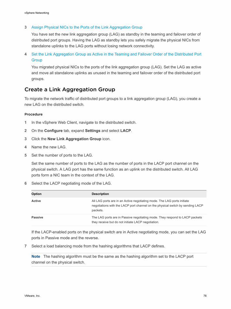
3 Assign Physical NICs to the Ports of the Link Aggregation Group
You have set the new link aggregation group (LAG) as standby in the teaming and failover order of distributed port groups. Having the LAG as standby lets you safely migrate the physical NICs from standalone uplinks to the LAG ports without losing network connectivity.
4 Set the Link Aggregation Group as Active in the Teaming and Failover Order of the Distributed Port Group
You migrated physical NICs to the ports of the link aggregation group (LAG). Set the LAG as active and move all standalone uplinks as unused in the teaming and failover order of the distributed port groups.
Create a Link Aggregation GroupTo migrate the network traffic of distributed port groups to a link aggregation group (LAG), you create a new LAG on the distributed switch.
Procedure
1 In the vSphere Web Client, navigate to the distributed switch.
2 On the Configure tab, expand Settings and select LACP.
3 Click the New Link Aggregation Group icon.
4 Name the new LAG.
5 Set the number of ports to the LAG.
Set the same number of ports to the LAG as the number of ports in the LACP port channel on the physical switch. A LAG port has the same function as an uplink on the distributed switch. All LAG ports form a NIC team in the context of the LAG.
6 Select the LACP negotiating mode of the LAG.
Option Description
Active All LAG ports are in an Active negotiating mode. The LAG ports initiate negotiations with the LACP port channel on the physical switch by sending LACP packets.
Passive The LAG ports are in Passive negotiating mode. They respond to LACP packets they receive but do not initiate LACP negotiation.
If the LACP-enabled ports on the physical switch are in Active negotiating mode, you can set the LAG ports in Passive mode and the reverse.
7 Select a load balancing mode from the hashing algorithms that LACP defines.
Note The hashing algorithm must be the same as the hashing algorithm set to the LACP port channel on the physical switch.
vSphere Networking
VMware, Inc. 78
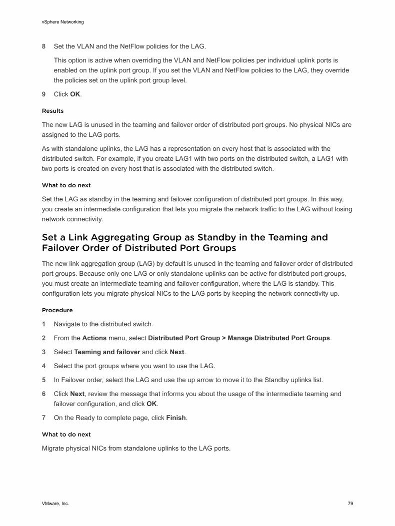
8 Set the VLAN and the NetFlow policies for the LAG.
This option is active when overriding the VLAN and NetFlow policies per individual uplink ports is enabled on the uplink port group. If you set the VLAN and NetFlow policies to the LAG, they override the policies set on the uplink port group level.
9 Click OK.
Results
The new LAG is unused in the teaming and failover order of distributed port groups. No physical NICs are assigned to the LAG ports.
As with standalone uplinks, the LAG has a representation on every host that is associated with the distributed switch. For example, if you create LAG1 with two ports on the distributed switch, a LAG1 with two ports is created on every host that is associated with the distributed switch.
What to do next
Set the LAG as standby in the teaming and failover configuration of distributed port groups. In this way, you create an intermediate configuration that lets you migrate the network traffic to the LAG without losing network connectivity.
Set a Link Aggregating Group as Standby in the Teaming and Failover Order of Distributed Port GroupsThe new link aggregation group (LAG) by default is unused in the teaming and failover order of distributed port groups. Because only one LAG or only standalone uplinks can be active for distributed port groups, you must create an intermediate teaming and failover configuration, where the LAG is standby. This configuration lets you migrate physical NICs to the LAG ports by keeping the network connectivity up.
Procedure
1 Navigate to the distributed switch.
2 From the Actions menu, select Distributed Port Group > Manage Distributed Port Groups.
3 Select Teaming and failover and click Next.
4 Select the port groups where you want to use the LAG.
5 In Failover order, select the LAG and use the up arrow to move it to the Standby uplinks list.
6 Click Next, review the message that informs you about the usage of the intermediate teaming and failover configuration, and click OK.
7 On the Ready to complete page, click Finish.
What to do next
Migrate physical NICs from standalone uplinks to the LAG ports.
vSphere Networking
VMware, Inc. 79
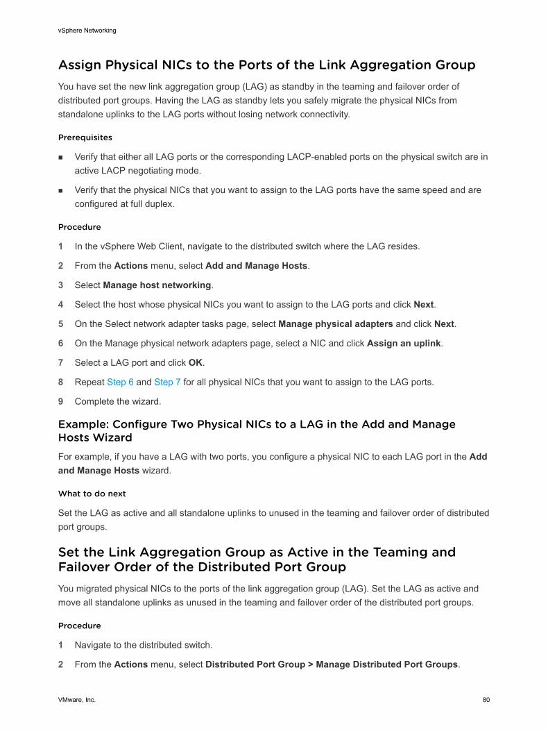
Assign Physical NICs to the Ports of the Link Aggregation GroupYou have set the new link aggregation group (LAG) as standby in the teaming and failover order of distributed port groups. Having the LAG as standby lets you safely migrate the physical NICs from standalone uplinks to the LAG ports without losing network connectivity.
Prerequisites
n Verify that either all LAG ports or the corresponding LACP-enabled ports on the physical switch are in active LACP negotiating mode.
n Verify that the physical NICs that you want to assign to the LAG ports have the same speed and are configured at full duplex.
Procedure
1 In the vSphere Web Client, navigate to the distributed switch where the LAG resides.
2 From the Actions menu, select Add and Manage Hosts.
3 Select Manage host networking.
4 Select the host whose physical NICs you want to assign to the LAG ports and click Next.
5 On the Select network adapter tasks page, select Manage physical adapters and click Next.
6 On the Manage physical network adapters page, select a NIC and click Assign an uplink.
7 Select a LAG port and click OK.
8 Repeat Step 6 and Step 7 for all physical NICs that you want to assign to the LAG ports.
9 Complete the wizard.
Example: Configure Two Physical NICs to a LAG in the Add and Manage Hosts WizardFor example, if you have a LAG with two ports, you configure a physical NIC to each LAG port in the Add and Manage Hosts wizard.
What to do next
Set the LAG as active and all standalone uplinks to unused in the teaming and failover order of distributed port groups.
Set the Link Aggregation Group as Active in the Teaming and Failover Order of the Distributed Port GroupYou migrated physical NICs to the ports of the link aggregation group (LAG). Set the LAG as active and move all standalone uplinks as unused in the teaming and failover order of the distributed port groups.
Procedure
1 Navigate to the distributed switch.
2 From the Actions menu, select Distributed Port Group > Manage Distributed Port Groups.
vSphere Networking
VMware, Inc. 80

3 Select Teaming and failover and click Next.
4 Select the port groups where you set the LAG as standby and click Next.
5 In Failover order, use the up and down arrows to move the LAG in the Active list, all standalone uplinks in the Unused list, and leave the Standby list empty.
6 Click Next and click Finish.
Results
You safely migrated network traffic from standalone uplinks to a LAG for distributed port groups and created a valid LACP teaming and failover configuration for the groups.
Example: Topology of a Distributed Switch that Uses a LAGIf you configure a LAG with two ports to handle the traffic of a distributed port group, you can check the topology of the distributed switch to view how it changed as a result of the new configuration.
Figure 5-2. Distributed Switch Topology with a LAG
Edit a Link Aggregation GroupEdit the settings of a link aggregation group ( LAG) if you need to add more ports to the group or change the LACP negotiating mode, the load balancing algorithm, or the VLAN and NetFlow policies.
Procedure
1 In the vSphere Web Client, navigate to the vSphere Distributed Switch.
2 On the Configure tab, expand Settings and select LACP.
3 Click the New Link Aggregation Group icon.
4 In the Name text box, type a new name for the LAG.
5 Change the number of ports for the LAG if you want to add more physical NICs to it.
The new NICs must be connected to ports that are part of an LACP port channel on the physical switch.
vSphere Networking
VMware, Inc. 81
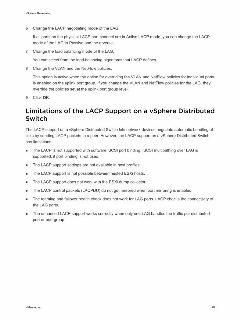
6 Change the LACP negotiating mode of the LAG.
If all ports on the physical LACP port channel are in Active LACP mode, you can change the LACP mode of the LAG to Passive and the reverse.
7 Change the load balancing mode of the LAG.
You can select from the load balancing algorithms that LACP defines.
8 Change the VLAN and the NetFlow policies.
This option is active when the option for overriding the VLAN and NetFlow policies for individual ports is enabled on the uplink port group. If you change the VLAN and NetFlow policies for the LAG, they override the policies set at the uplink port group level.
9 Click OK.
Limitations of the LACP Support on a vSphere Distributed SwitchThe LACP support on a vSphere Distributed Switch lets network devices negotiate automatic bundling of links by sending LACP packets to a peer. However, the LACP support on a vSphere Distributed Switch has limitations.
n The LACP is not supported with software iSCSI port binding. iSCSI multipathing over LAG is supported, if port binding is not used.
n The LACP support settings are not available in host profiles.
n The LACP support is not possible between nested ESXi hosts.
n The LACP support does not work with the ESXi dump collector.
n The LACP control packets (LACPDU) do not get mirrored when port mirroring is enabled.
n The teaming and failover health check does not work for LAG ports. LACP checks the connectivity of the LAG ports.
n The enhanced LACP support works correctly when only one LAG handles the traffic per distributed port or port group.
vSphere Networking
VMware, Inc. 82
Backing Up and Restoring Networking Configurations 6vSphere enables you to backup and restore the configuration of a vSphere Distributed Switch , distributed and uplink port groups in cases of invalid changes or a transfer to another deployment.
This chapter includes the following topics:
n Backing Up and Restoring a vSphere Distributed Switch Configuration
n Export, Import, and Restore vSphere Distributed Port Group Configurations
Backing Up and Restoring a vSphere Distributed Switch ConfigurationvCenter Server provides the ability to backup and restore the configuration of a vSphere Distributed Switch. You can restore the virtual network configuration in cases of database or upgrade failure. You can also use a saved switch configuration as a template to create a copy of the switch in the same or a new vSphere environment.
You can import or export a configuration of a distributed switch including its port groups. For information about exporting, importing, and restoring a port group configuration, see Export, Import, and Restore vSphere Distributed Port Group Configurations.
Note You can use a saved configuration file to restore policies and hosts associations on the distributed switch. You cannot restore the connection of physical NICs to uplink ports or ports of link aggregation groups.
Export vSphere Distributed Switch ConfigurationsYou can export vSphere Distributed Switch and distributed port group configurations to a file. The file preserves valid network configurations, enabling transfer of these configurations to other environments.
Procedure
1 In the vSphere Web Client, navigate to the distributed switch.
2 Right-click the distributed switch and select Settings > Export Configuration.
3 Choose to export the distributed switch configuration, or export the distributed switch configuration and all port groups.
VMware, Inc. 83

4 (Optional) Enter notes about this configuration in the Descriptions field.
5 Click OK.
6 Click Yes to save the configuration file to your local system.
What to do next
Use the exported configuration file to do the following tasks:
n Create a copy of the exported distributed switch in a vSphere environment. See Import a vSphere Distributed Switch Configuration.
n Overwrite the settings on an existing distributed switch. See Restore a vSphere Distributed Switch Configuration.
You can also export, import, and restore only port group configurations. See Export, Import, and Restore vSphere Distributed Port Group Configurations.
Import a vSphere Distributed Switch ConfigurationImport a stored configuration file to create a new vSphere Distributed Switch or to restore a switch that has been deleted earlier.
The configuration file contains the networking settings of the switch. By using it you can also replicate the switch in other virtual environments.
Note You can use a saved configuration file to replicate the switch instance, its host associations, and policies. You cannot replicate the connection of physical NICs to uplink ports or ports on link aggregation groups.
Procedure
1 In the vSphere Web Client, navigate to a data center.
2 Right-click the data center and select Distributed Switch > Import Distributed Switch.
3 Browse to the location of the configuration file.
4 To assign the keys from the configuration file to the switch and its port groups, select the Preserve original distributed switch and port group identifiers check box and click Next.
You can use the Preserve original distributed switch and port group identifiers option in the following cases:
n Recreate a deleted switch.
n Restore a switch whose upgrade has failed.
All port groups are recreated and the hosts that have been connected to the switch are added again.
5 Review the settings for the switch and click Finish.
vSphere Networking
VMware, Inc. 84
Results
A new distributed switch is created with settings from the configuration file. If you have included distributed port group information in the configuration file, the port groups are also created.
Restore a vSphere Distributed Switch ConfigurationUse the restore option to reset the configuration of an existing distributed switch to the settings in the configuration file. Restoring a distributed switch changes the settings on the selected switch back to the settings saved in the configuration file.
Note You can use a saved configuration file to restore policies and hosts associations on the distributed switch. You cannot restore the connection of physical NICs to uplink ports or ports of link aggregation groups.
Procedure
1 In the vSphere Web Client, navigate to the distributed switch.
2 Right-click the distributed switch in the navigator and select Settings > Restore Configuration.
3 Browse for the configuration backup file to use.
4 Select Restore distributed switch and all port groups or Restore distributed switch only and click Next
5 Review the summary information for the restore.
Restoring a distributed switch will overwrite the current settings of the distributed switch and its port groups. It will not delete existing port groups that are not part of the configuration file.
6 Click Finish.
The distributed switch configuration has been restored to the settings in the configuration file.
Export, Import, and Restore vSphere Distributed Port Group ConfigurationsYou can export vSphere distributed port group configurations to a file. The configuration file allows you to preserve valid port group configurations, enabling distribution of these configurations to other deployments.
You can export port group information at the same time you export distributed switch configurations. See Backing Up and Restoring a vSphere Distributed Switch Configuration.
Export vSphere Distributed Port Group ConfigurationsYou can export a distributed port group configurations to a file. The configuration preserves valid network configurations, enabling distribution of these configurations to other deployments.
vSphere Networking
VMware, Inc. 85
Procedure
1 Locate a distributed port group in the vSphere Web Client.
a Select a distributed switch and click the Networks tab.
b Click Distributed Port Groups.
2 Right-click the distributed port group and select Export Configuration.
3 (Optional) In the Descriptions field, type notes about this configuration.
4 Click OK.
Click Yes to save the configuration file to your local system.
Results
You now have a configuration file that contains all the settings for the selected distributed port group. You can use this file to create multiple copies of this configuration on an existing deployment, or overwrite settings of existing distributed port groups to conform to the selected settings.
What to do next
You can use the exported configuration file to do the following tasks:
n To create a copy of the exported distributed port group, see Import a vSphere Distributed Port Group Configuration.
n To overwrite settings on an existing distributed port group, see Restore a vSphere Distributed Port Group Configuration.
Import a vSphere Distributed Port Group ConfigurationUse import to create a distributed port group from a configuration file.
If an existing port group has the same name as the imported port group, the new port group name has a number appended in parentheses. The settings from the imported configuration are applied to the new port group and the settings of the original port group remain unchanged.
Procedure
1 In the vSphere Web Client, navigate to the distributed switch.
2 Right-click the distributed switch and select Distributed Port Group > Import Distributed Port Group.
3 Browse to the location of your saved configuration file and click Next.
4 Review the import settings before completing the import.
5 Click Finish.
vSphere Networking
VMware, Inc. 86
Restore a vSphere Distributed Port Group ConfigurationUse the restore option to reset the configuration of an existing distributed port group to the settings in a configuration file.
Procedure
1 Locate a distributed port group in the vSphere Web Client.
a Select a distributed switch and click the Networks tab.
b Click Distributed Port Groups.
2 Right-click the distributed port group and select Restore Configuration.
3 Select one of the following and click Next:
u Restore to previous configuration to roll your port group configuration back one step. You cannot restore the port group configuration completely if you have performed more than one step.
u Restore configuration from a file lets you restore the port group configuration from an exported backup file. You can also use a distributed switch backup file as long as it contains configuration information for the port group.
4 Review the summary information for the restore.
The restore operation overwrites the current settings of the distributed port group with the settings from the backup. If you are restoring the port group configuration from a switch backup file, the restore operation does not delete existing port groups that are not a part of the file.
5 Click Finish.
vSphere Networking
VMware, Inc. 87
Rollback and Recovery of the Management Network 7You can prevent and recover from misconfiguration of the management network by using the rollback and recovery support of the vSphere Distributed Switch and vSphere Standard Switch.
Rollback is available for use on both standard and distributed switches. To fix invalid configuration of the management network, you can connect directly to a host to fix the issues through the DCUI.
This chapter includes the following topics:
n vSphere Networking Rollback
n Resolve Errors in the Management Network Configuration on a vSphere Distributed Switch
vSphere Networking RollbackBy rolling configuration changes back, vSphere protects hosts from losing connection to vCenter Server as a result from misconfiguration of the management network.
In vSphere networking rollback is enabled by default. However, you can enable or disable rollbacks at the vCenter Server level.
Host Networking RollbacksHost networking rollbacks occur when an invalid change is made to the networking configuration for the connection with vCenter Server. Every network change that disconnects a host also triggers a rollback. The following examples of changes to the host networking configuration might trigger a rollback:
n Updating the speed or duplex of a physical NIC.
n Updating DNS and routing settings.
n Updating teaming and failover policies or traffic shaping policies of a standard port group that contains the management VMkernel network adapter.
n Updating the VLAN of a standard port group that contains the management VMkernel network adapter.
n Increasing the MTU of management VMkernel network adapter and its switch to values not supported by the physical infrastructure.
n Changing the IP settings of management VMkernel network adapters.
VMware, Inc. 88
n Removing the management VMkernel network adapter from a standard or distributed switch.
n Removing a physical NIC of a standard or distributed switch containing the management VMkernel network adapter.
n Migrating the management VMkernel adapter from vSphere standard to distributed switch.
If a network disconnects for any of these reasons, the task fails and the host reverts to the last valid configuration.
vSphere Distributed Switch RollbacksDistributed switch rollbacks occur when invalid updates are made to distributed switches, distributed port groups, or distributed ports. The following changes to the distributed switch configuration trigger a rollback:
n Changing the MTU of a distributed switch.
n Changing the following settings in the distributed port group of the management VMkernel network adapter:
n Teaming and failover
n VLAN
n Traffic shaping
n Blocking all ports in the distributed port group containing the management VMkernel network adapter.
n Overriding the policies on at the level of the distributed port for the management VMkernel network adapter.
If a configuration becomes invalid because of any of the changes, one or more hosts might become out of synchronization with the distributed switch.
If you know where the conflicting configuration setting is located, you can manually correct the setting. For example, if you have migrated a management VMkernel network adapter to a new VLAN, the VLAN might not be actually trunked on the physical switch. When you correct the physical switch configuration, the next distributed switch-to-host synchronization will resolve the configuration problem.
If you are not sure where the problem exists, you can restore the state of the distributed switch or distributed port group to an earlier configuration. See Restore a vSphere Distributed Port Group Configuration.
Disable Network RollbackRollback is enabled by default in vSphere. You can disable rollback in vCenter Server by using the vSphere Web Client.
Procedure
1 In the vSphere Web Client, navigate to a vCenter Server instance.
2 On the Configure tab, expand Settings and select Advanced Settings.
vSphere Networking
VMware, Inc. 89
3 Click Edit.
4 Select the config.vpxd.network.rollback key, and change the value to false.
If the key is not present, you can add it and set the value to false.
5 Click OK.
6 Restart vCenter Server to apply the changes.
Disable Network Rollback by Using the vCenter Server Configuration FileRollback is enabled by default in vSphere. You can disable rollback by editing the vpxd.cfg configuration file of vCenter Server directly.
Procedure
1 On the host machine of vCenter Server, navigate to the directory that contains the configuration file:
n On a Windows Server operating system, the location of the directory is C:\ProgramData\VMware\CIS\cfg\vmware-vpx.
n On the vCenter Server Appliance, the location of the directory is /etc/vmware-vpx.
2 Open the vpxd.cfg file for editing.
3 In the <network> element, set the <rollback> element to false:
<config>
<vpxd>
<network>
<rollback>false</rollback>
</network>
</vpxd>
</config>
4 Save and close the file.
5 Restart the vCenter Server system.
Resolve Errors in the Management Network Configuration on a vSphere Distributed SwitchYou can use the Direct Console User Interface (DCUI) to restore the connection between vCenter Server and a host that accesses the management network through a distributed switch.
If networking rollback is disabled, misconfiguring the port group for the management network on the distributed switch leads to loss of connection between vCenter Server and the hosts that are added to the switch. You have to use the DCUI to connect each host individually.
vSphere Networking
VMware, Inc. 90
If the uplinks that you use to restore the management network are also used by VMkernel adapters that handle other types of traffic (vMotion, Fault Tolerance, and so on), the adapters loose network connectivity after the restore.
For more information about accessing and using the DCUI, see the vSphere Security documentation.
Note Recovery of the management connection on a distributed switch is not supported on stateless ESXi instances.
Prerequisites
Verify that the management network is configured on a port group on the distributed switch.
Procedure
1 Connect to the DCUI of the host.
2 From the Network Restore Options menu, select Restore vDS.
3 Configure the uplinks and optionally the VLAN for the management network.
4 Apply the configuration.
Results
The DCUI creates a local ephemeral port and applies the values you provided for the VLAN and uplinks. The DCUI moves the VMkernel adapter for the management network to the new local port to restore connectivity to vCenter Server.
What to do next
After the connection of the host to vCenter Server is restored, correct the configuration of the distributed port group and re-add the VMkernel adapter to the group.
vSphere Networking
VMware, Inc. 91
Networking Policies 8Policies set at the standard switch or distributed port group level apply to all of the port groups on the standard switch or to ports in the distributed port group. The exceptions are the configuration options that are overridden at the standard port group or distributed port level.
Watch the video about applying networking policies on vSphere standard and distributed switches.
Working with Networking Policies (http://link.brightcove.com/services/player/bcpid2296383276001?bctid=ref:video_working_with_network_policies)
n Applying Networking Policies on a vSphere Standard or Distributed Switch
You apply networking policies differently on vSphere Standard Switches and vSphere Distributed Switches. Not all policies that are available for a vSphere Distributed Switch are also available for a vSphere Standard Switch.
n Configure Overriding Networking Policies on Port Level
To apply different policies for distributed ports, you configure the per-port overriding of the policies that are set at the port group level. You can also enable the reset of any configuration that is set on per-port level when a distributed port disconnects from a virtual machine.
n Teaming and Failover Policy
NIC teaming lets you increase the network capacity of a virtual switch by including two or more physical NICs in a team. To determine how the traffic is rerouted in case of adapter failure, you include physical NICs in a failover order. To determine how the virtual switch distributes the network traffic between the physical NICs in a team, you select load balancing algorithms depending on the needs and capabilities of your environment.
n VLAN Policy
VLAN policies determine how VLANs function across your network environment.
n Security Policy
Networking security policy provides protection of traffic against MAC address impersonation and unwanted port scanning
VMware, Inc. 92
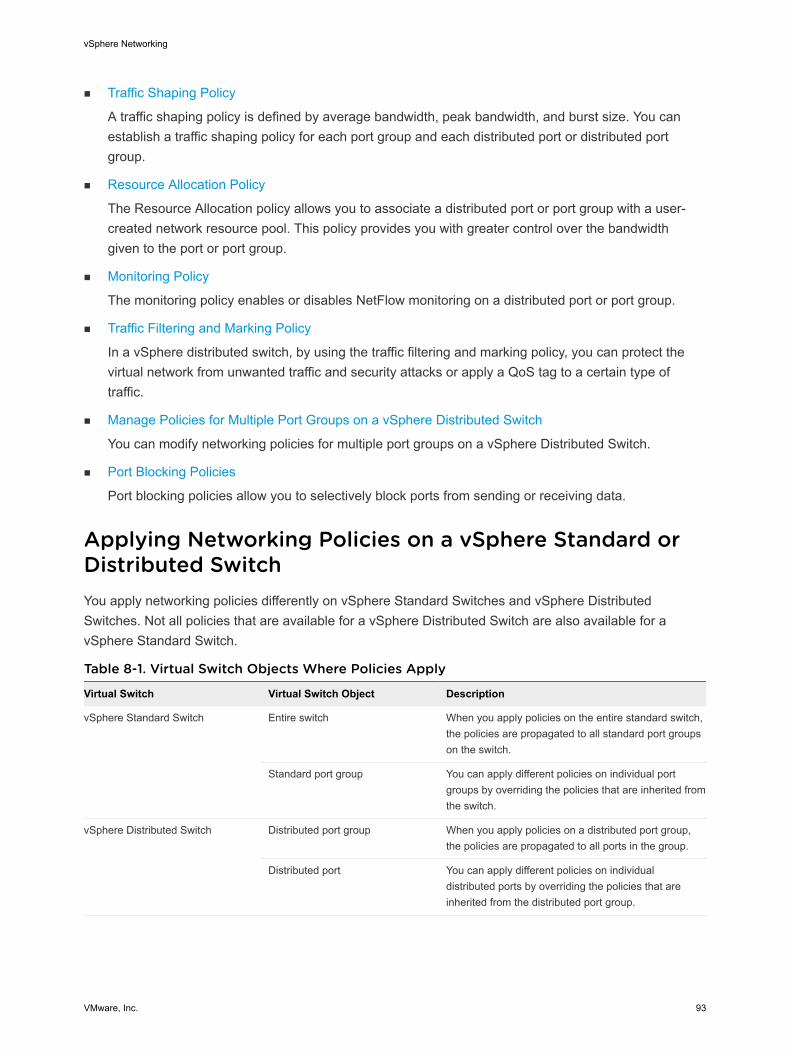
n Traffic Shaping Policy
A traffic shaping policy is defined by average bandwidth, peak bandwidth, and burst size. You can establish a traffic shaping policy for each port group and each distributed port or distributed port group.
n Resource Allocation Policy
The Resource Allocation policy allows you to associate a distributed port or port group with a user-created network resource pool. This policy provides you with greater control over the bandwidth given to the port or port group.
n Monitoring Policy
The monitoring policy enables or disables NetFlow monitoring on a distributed port or port group.
n Traffic Filtering and Marking Policy
In a vSphere distributed switch, by using the traffic filtering and marking policy, you can protect the virtual network from unwanted traffic and security attacks or apply a QoS tag to a certain type of traffic.
n Manage Policies for Multiple Port Groups on a vSphere Distributed Switch
You can modify networking policies for multiple port groups on a vSphere Distributed Switch.
n Port Blocking Policies
Port blocking policies allow you to selectively block ports from sending or receiving data.
Applying Networking Policies on a vSphere Standard or Distributed SwitchYou apply networking policies differently on vSphere Standard Switches and vSphere Distributed Switches. Not all policies that are available for a vSphere Distributed Switch are also available for a vSphere Standard Switch.
Table 8-1. Virtual Switch Objects Where Policies Apply
Virtual Switch Virtual Switch Object Description
vSphere Standard Switch Entire switch When you apply policies on the entire standard switch, the policies are propagated to all standard port groups on the switch.
Standard port group You can apply different policies on individual port groups by overriding the policies that are inherited from the switch.
vSphere Distributed Switch Distributed port group When you apply policies on a distributed port group, the policies are propagated to all ports in the group.
Distributed port You can apply different policies on individual distributed ports by overriding the policies that are inherited from the distributed port group.
vSphere Networking
VMware, Inc. 93
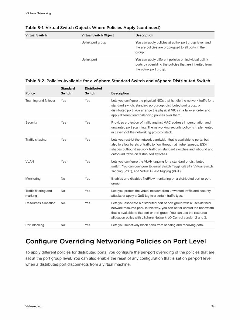
Table 8-1. Virtual Switch Objects Where Policies Apply (continued)
Virtual Switch Virtual Switch Object Description
Uplink port group You can apply policies at uplink port group level, and the are policies are propagated to all ports in the group.
Uplink port You can apply different policies on individual uplink ports by overriding the policies that are inherited from the uplink port group.
Table 8-2. Policies Available for a vSphere Standard Switch and vSphere Distributed Switch
PolicyStandard Switch
Distributed Switch Description
Teaming and failover Yes Yes Lets you configure the physical NICs that handle the network traffic for a standard switch, standard port group, distributed port group, or distributed port. You arrange the physical NICs in a failover order and apply different load balancing policies over them.
Security Yes Yes Provides protection of traffic against MAC address impersonation and unwanted port scanning. The networking security policy is implemented in Layer 2 of the networking protocol stack.
Traffic shaping Yes Yes Lets you restrict the network bandwidth that is available to ports, but also to allow bursts of traffic to flow through at higher speeds. ESXi shapes outbound network traffic on standard switches and inbound and outbound traffic on distributed switches.
VLAN Yes Yes Lets you configure the VLAN tagging for a standard or distributed switch. You can configure External Switch Tagging(EST), Virtual Switch Tagging (VST), and Virtual Guest Tagging (VGT).
Monitoring No Yes Enables and disables NetFlow monitoring on a distributed port or port group.
Traffic filtering and marking
No Yes Lest you protect the virtual network from unwanted traffic and security attacks or apply a QoS tag to a certain traffic type.
Resources allocation No Yes Lets you associate a distributed port or port group with a user-defined network resource pool. In this way, you can better control the bandwidth that is available to the port or port group. You can use the resource allocation policy with vSphere Network I/O Control version 2 and 3.
Port blocking No Yes Lets you selectively block ports from sending and receiving data.
Configure Overriding Networking Policies on Port LevelTo apply different policies for distributed ports, you configure the per-port overriding of the policies that are set at the port group level. You can also enable the reset of any configuration that is set on per-port level when a distributed port disconnects from a virtual machine.
vSphere Networking
VMware, Inc. 94
Procedure
1 Locate a distributed port group in the vSphere Web Client.
a Select a distributed switch and click the Networks tab.
b Click Distributed Port Groups.
2 Right-click the distributed port group and select Edit Settings.
3 Select the Advanced page.
Option Description
Configure reset at disconnect From the drop-down menu, enable or disable reset at disconnect.
When a distributed port is disconnected from a virtual machine, the configuration of the distributed port is reset to the distributed port group setting. Any per-port overrides are discarded.
Override port policies Select the distributed port group policies to be overridden on a per-port level.
4 (Optional) Use the policy pages to set overrides for each port policy.
5 Click OK.
Teaming and Failover PolicyNIC teaming lets you increase the network capacity of a virtual switch by including two or more physical NICs in a team. To determine how the traffic is rerouted in case of adapter failure, you include physical NICs in a failover order. To determine how the virtual switch distributes the network traffic between the physical NICs in a team, you select load balancing algorithms depending on the needs and capabilities of your environment.
NIC Teaming PolicyYou can use NIC teaming to connect a virtual switch to multiple physical NICs on a host to increase the network bandwidth of the switch and to provide redundancy. A NIC team can distribute the traffic between its members and provide passive failover in case of adapter failure or network outage. You set NIC teaming policies at virtual switch or port group level for a vSphere Standard Switch and at a port group or port level for a vSphere Distributed Switch.
Note All ports on the physical switch in the same team must be in the same Layer 2 broadcast domain.
Load Balancing PolicyThe Load Balancing policy determines how network traffic is distributed between the network adapters in a NIC team. vSphere virtual switches load balance only the outgoing traffic. Incoming traffic is controlled by the load balancing policy on the physical switch.
For more information about each load balancing algorithm, see Load Balancing Algorithms Available for Virtual Switches.
vSphere Networking
VMware, Inc. 95

Network Failure Detection PolicyYou can specify one of the following methods that a virtual switch uses for failover detection.
Link status only Relies only on the link status that the network adapter provides. Detects failures, such as removed cables and physical switch power failures. However, link status does not detect the following configuration errors:
n Physical switch port that is blocked by spanning tree or is misconfigured to the wrong VLAN .
n Pulled cable that connects a physical switch to another networking devices, for example, an upstream switch .
Beacon probing Sends out and listens for Ethernet broadcast frames, or beacon probes, that physical NICs send to detect link failure in all physical NICs in a team. ESXi hosts send beacon packets every second. Beacon probing is most useful to detect failures in the closest physical switch to the ESXi host, where the failure does not cause a link-down event for the host.
Use beacon probing with three or more NICs in a team because ESXi can detect failures of a single adapter. If only two NICs are assigned and one of them loses connectivity, the switch cannot determine which NIC needs to be taken out of service because both do not receive beacons and as a result all packets sent to both uplinks. Using at least three NICs in such a team allows for n-2 failures where n is the number of NICs in the team before reaching an ambiguous situation.
Failback PolicyBy default, a failback policy is enabled on a NIC team. If a failed physical NIC returns online, the virtual switch sets the NIC back to active by replacing the standby NIC that took over its slot.
If the physical NIC that stands first in the failover order experiences intermittent failures, the failback policy might lead to frequent changes in the NIC that is used. The physical switch sees frequent changes in MAC addresses, and the physical switch port might not accept traffic immediately when an adapter becomes online. To minimize such delays, you might consider changing the following settings on the physical switch:
n Disable Spanning Tree Protocol (STP) on physical NICs that are connected to ESXi hosts .
n For Cisco based networks, enable PortFast mode for access interfaces or PortfFast trunk mode for trunk interfaces. This might save about 30 seconds during the initialization of the physical switch port.
n Disable the trunking negotiation.
vSphere Networking
VMware, Inc. 96
Notify Switches PolicyBy using the notify switches policy, you can determine how the ESXi host communicates failover events. When a physical NIC connects to the virtual switch or when traffic is rerouted to a different physical NIC in the team, the virtual switch sends notifications over the network to update the lookup tables on physical switches. Notifying the physical switch offers lowest latency when a failover or a migration with vSphere vMotion occurs.
Load Balancing Algorithms Available for Virtual SwitchesYou can configure various load balancing algorithms on a virtual switch to determine how network traffic is distributed between the physical NICs in a team.
n Route Based on Originating Virtual Port
The virtual switch selects uplinks based on the virtual machine port IDs on the vSphere Standard Switch or vSphere Distributed Switch.
n Route Based on Source MAC Hash
The virtual switch selects an uplink for a virtual machine based on the virtual machine MAC address. To calculate an uplink for a virtual machine, the virtual switch uses the virtual machine MAC address and the number of uplinks in the NIC team.
n Route Based on IP Hash
The virtual switch selects uplinks for virtual machines based on the source and destination IP address of each packet.
n Route Based on Physical NIC Load
Route Based on Physical NIC Load is based on Route Based on Originating Virtual Port, where the virtual switch checks the actual load of the uplinks and takes steps to reduce it on overloaded uplinks. Available only for vSphere Distributed Switch.
n Use Explicit Failover Order
No actual load balancing is available with this policy. The virtual switch always uses the uplink that stands first in the list of Active adapters from the failover order and that passes failover detection criteria. If no uplinks in the Active list are available, the virtual switch uses the uplinks from the Standby list.
Route Based on Originating Virtual PortThe virtual switch selects uplinks based on the virtual machine port IDs on the vSphere Standard Switch or vSphere Distributed Switch.
Route Based on Originating Virtual Port is the default load balancing method on the vSphere Standard Switch and vSphere Distributed Switch.
vSphere Networking
VMware, Inc. 97

Each virtual machine running on an ESXi host has an associated virtual port ID on the virtual switch. To calculate an uplink for a virtual machine, the virtual switch uses the virtual machine port ID and the number of uplinks in the NIC team. After the virtual switch selects an uplink for a virtual machine, it always forwards traffic through the same uplink for this virtual machine as long as the machine runs on the same port. The virtual switch calculates uplinks for virtual machines only once, unless uplinks are added or removed from the NIC team.
The port ID of a virtual machine is fixed while the virtual machine runs on the same host. If you migrate, power off, or delete the virtual machine, its port ID on the virtual switch becomes free. The virtual switch stops sending traffic to this port, which reduces the overall traffic for its associated uplink. If a virtual machine is powered on or migrated, it might appear on a different port and use the uplink, which is associated with the new port.
Table 8-3. Considerations on Using Route Based on Originating Virtual Port
Considerations Description
Advantages n An even distribution of traffic if the number virtual NICs is greater than the number of physical NICs in the team.
n Low resource consumption, because in most cases the virtual switch calculates uplinks for virtual machines only once.
n No changes on the physical switch are required.
Disadvantages n The virtual switch is not aware of the traffic load on the uplinks and it does not load balance the traffic to uplinks that are less used.
n The bandwidth that is available to a virtual machine is limited to the speed of the uplink that is associated with the relevant port ID, unless the virtual machine has more than one virtual NIC.
Route Based on Source MAC HashThe virtual switch selects an uplink for a virtual machine based on the virtual machine MAC address. To calculate an uplink for a virtual machine, the virtual switch uses the virtual machine MAC address and the number of uplinks in the NIC team.
vSphere Networking
VMware, Inc. 98
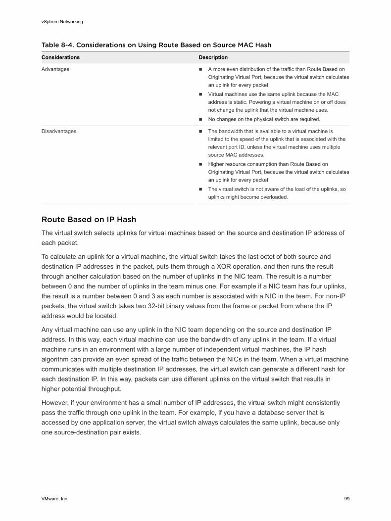
Table 8-4. Considerations on Using Route Based on Source MAC Hash
Considerations Description
Advantages n A more even distribution of the traffic than Route Based on Originating Virtual Port, because the virtual switch calculates an uplink for every packet.
n Virtual machines use the same uplink because the MAC address is static. Powering a virtual machine on or off does not change the uplink that the virtual machine uses.
n No changes on the physical switch are required.
Disadvantages n The bandwidth that is available to a virtual machine is limited to the speed of the uplink that is associated with the relevant port ID, unless the virtual machine uses multiple source MAC addresses.
n Higher resource consumption than Route Based on Originating Virtual Port, because the virtual switch calculates an uplink for every packet.
n The virtual switch is not aware of the load of the uplinks, so uplinks might become overloaded.
Route Based on IP HashThe virtual switch selects uplinks for virtual machines based on the source and destination IP address of each packet.
To calculate an uplink for a virtual machine, the virtual switch takes the last octet of both source and destination IP addresses in the packet, puts them through a XOR operation, and then runs the result through another calculation based on the number of uplinks in the NIC team. The result is a number between 0 and the number of uplinks in the team minus one. For example if a NIC team has four uplinks, the result is a number between 0 and 3 as each number is associated with a NIC in the team. For non-IP packets, the virtual switch takes two 32-bit binary values from the frame or packet from where the IP address would be located.
Any virtual machine can use any uplink in the NIC team depending on the source and destination IP address. In this way, each virtual machine can use the bandwidth of any uplink in the team. If a virtual machine runs in an environment with a large number of independent virtual machines, the IP hash algorithm can provide an even spread of the traffic between the NICs in the team. When a virtual machine communicates with multiple destination IP addresses, the virtual switch can generate a different hash for each destination IP. In this way, packets can use different uplinks on the virtual switch that results in higher potential throughput.
However, if your environment has a small number of IP addresses, the virtual switch might consistently pass the traffic through one uplink in the team. For example, if you have a database server that is accessed by one application server, the virtual switch always calculates the same uplink, because only one source-destination pair exists.
vSphere Networking
VMware, Inc. 99
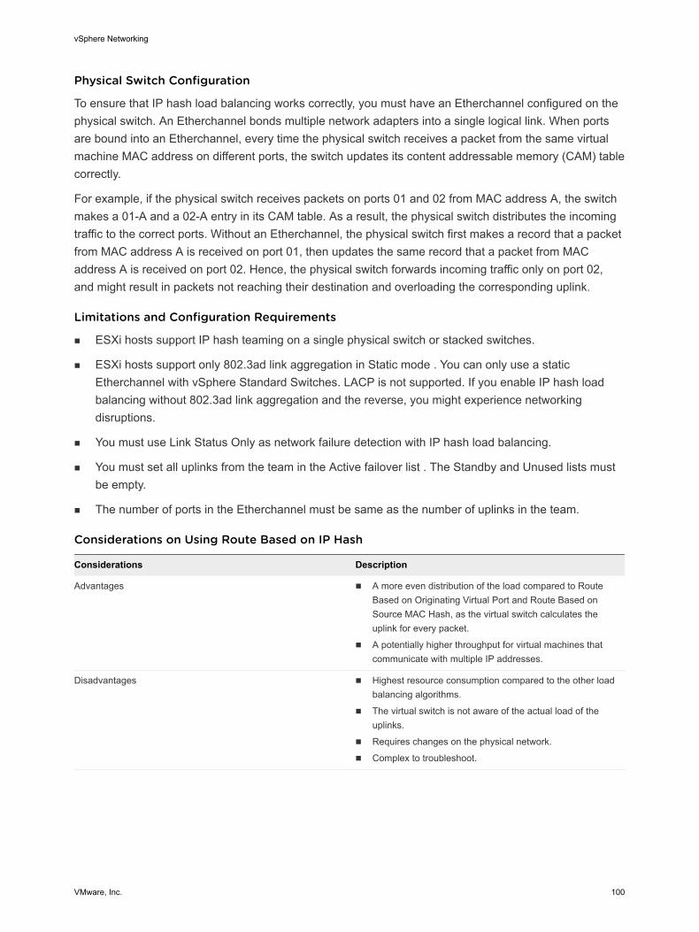
Physical Switch Configuration
To ensure that IP hash load balancing works correctly, you must have an Etherchannel configured on the physical switch. An Etherchannel bonds multiple network adapters into a single logical link. When ports are bound into an Etherchannel, every time the physical switch receives a packet from the same virtual machine MAC address on different ports, the switch updates its content addressable memory (CAM) table correctly.
For example, if the physical switch receives packets on ports 01 and 02 from MAC address A, the switch makes a 01-A and a 02-A entry in its CAM table. As a result, the physical switch distributes the incoming traffic to the correct ports. Without an Etherchannel, the physical switch first makes a record that a packet from MAC address A is received on port 01, then updates the same record that a packet from MAC address A is received on port 02. Hence, the physical switch forwards incoming traffic only on port 02, and might result in packets not reaching their destination and overloading the corresponding uplink.
Limitations and Configuration Requirements
n ESXi hosts support IP hash teaming on a single physical switch or stacked switches.
n ESXi hosts support only 802.3ad link aggregation in Static mode . You can only use a static Etherchannel with vSphere Standard Switches. LACP is not supported. If you enable IP hash load balancing without 802.3ad link aggregation and the reverse, you might experience networking disruptions.
n You must use Link Status Only as network failure detection with IP hash load balancing.
n You must set all uplinks from the team in the Active failover list . The Standby and Unused lists must be empty.
n The number of ports in the Etherchannel must be same as the number of uplinks in the team.
Considerations on Using Route Based on IP Hash
Considerations Description
Advantages n A more even distribution of the load compared to Route Based on Originating Virtual Port and Route Based on Source MAC Hash, as the virtual switch calculates the uplink for every packet.
n A potentially higher throughput for virtual machines that communicate with multiple IP addresses.
Disadvantages n Highest resource consumption compared to the other load balancing algorithms.
n The virtual switch is not aware of the actual load of the uplinks.
n Requires changes on the physical network.
n Complex to troubleshoot.
vSphere Networking
VMware, Inc. 100
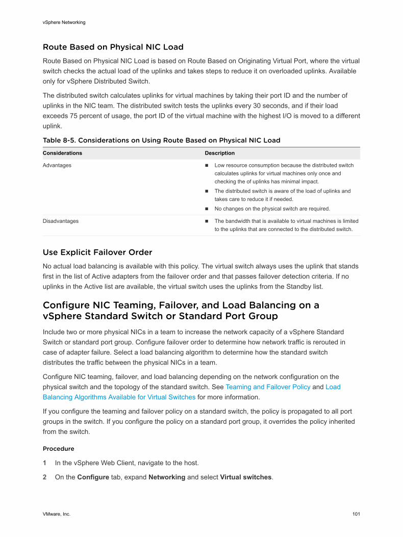
Route Based on Physical NIC LoadRoute Based on Physical NIC Load is based on Route Based on Originating Virtual Port, where the virtual switch checks the actual load of the uplinks and takes steps to reduce it on overloaded uplinks. Available only for vSphere Distributed Switch.
The distributed switch calculates uplinks for virtual machines by taking their port ID and the number of uplinks in the NIC team. The distributed switch tests the uplinks every 30 seconds, and if their load exceeds 75 percent of usage, the port ID of the virtual machine with the highest I/O is moved to a different uplink.
Table 8-5. Considerations on Using Route Based on Physical NIC Load
Considerations Description
Advantages n Low resource consumption because the distributed switch calculates uplinks for virtual machines only once and checking the of uplinks has minimal impact.
n The distributed switch is aware of the load of uplinks and takes care to reduce it if needed.
n No changes on the physical switch are required.
Disadvantages n The bandwidth that is available to virtual machines is limited to the uplinks that are connected to the distributed switch.
Use Explicit Failover OrderNo actual load balancing is available with this policy. The virtual switch always uses the uplink that stands first in the list of Active adapters from the failover order and that passes failover detection criteria. If no uplinks in the Active list are available, the virtual switch uses the uplinks from the Standby list.
Configure NIC Teaming, Failover, and Load Balancing on a vSphere Standard Switch or Standard Port GroupInclude two or more physical NICs in a team to increase the network capacity of a vSphere Standard Switch or standard port group. Configure failover order to determine how network traffic is rerouted in case of adapter failure. Select a load balancing algorithm to determine how the standard switch distributes the traffic between the physical NICs in a team.
Configure NIC teaming, failover, and load balancing depending on the network configuration on the physical switch and the topology of the standard switch. See Teaming and Failover Policy and Load Balancing Algorithms Available for Virtual Switches for more information.
If you configure the teaming and failover policy on a standard switch, the policy is propagated to all port groups in the switch. If you configure the policy on a standard port group, it overrides the policy inherited from the switch.
Procedure
1 In the vSphere Web Client, navigate to the host.
2 On the Configure tab, expand Networking and select Virtual switches.
vSphere Networking
VMware, Inc. 101
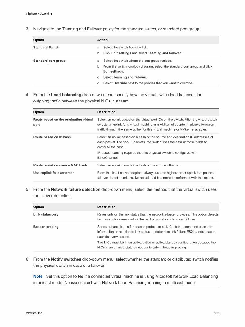
3 Navigate to the Teaming and Failover policy for the standard switch, or standard port group.
Option Action
Standard Switch a Select the switch from the list.
b Click Edit settings and select Teaming and failover.
Standard port group a Select the switch where the port group resides.
b From the switch topology diagram, select the standard port group and click Edit settings.
c Select Teaming and failover.d Select Override next to the policies that you want to override.
4 From the Load balancing drop-down menu, specify how the virtual switch load balances the
outgoing traffic between the physical NICs in a team.
Option Description
Route based on the originating virtual port
Select an uplink based on the virtual port IDs on the switch. After the virtual switch selects an uplink for a virtual machine or a VMkernel adapter, it always forwards traffic through the same uplink for this virtual machine or VMkernel adapter.
Route based on IP hash Select an uplink based on a hash of the source and destination IP addresses of each packet. For non-IP packets, the switch uses the data at those fields to compute the hash .
IP-based teaming requires that the physical switch is configured with EtherChannel.
Route based on source MAC hash Select an uplink based on a hash of the source Ethernet.
Use explicit failover order From the list of active adapters, always use the highest order uplink that passes failover detection criteria. No actual load balancing is performed with this option.
5 From the Network failure detection drop-down menu, select the method that the virtual switch uses
for failover detection.
Option Description
Link status only Relies only on the link status that the network adapter provides. This option detects failures such as removed cables and physical switch power failures.
Beacon probing Sends out and listens for beacon probes on all NICs in the team, and uses this information, in addition to link status, to determine link failure.ESXi sends beacon packets every second.
The NICs must be in an active/active or active/standby configuration because the NICs in an unused state do not participate in beacon probing.
6 From the Notify switches drop-down menu, select whether the standard or distributed switch notifies
the physical switch in case of a failover.
Note Set this option to No if a connected virtual machine is using Microsoft Network Load Balancing in unicast mode. No issues exist with Network Load Balancing running in multicast mode.
vSphere Networking
VMware, Inc. 102
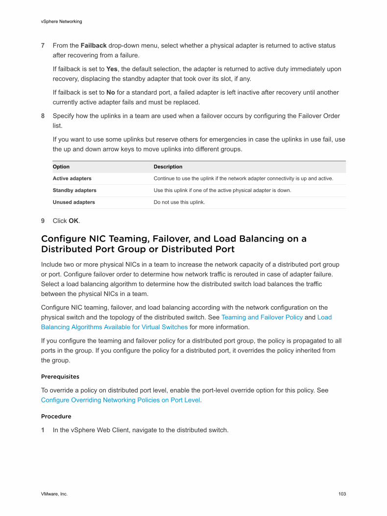
7 From the Failback drop-down menu, select whether a physical adapter is returned to active status after recovering from a failure.
If failback is set to Yes, the default selection, the adapter is returned to active duty immediately upon recovery, displacing the standby adapter that took over its slot, if any.
If failback is set to No for a standard port, a failed adapter is left inactive after recovery until another currently active adapter fails and must be replaced.
8 Specify how the uplinks in a team are used when a failover occurs by configuring the Failover Order list.
If you want to use some uplinks but reserve others for emergencies in case the uplinks in use fail, use the up and down arrow keys to move uplinks into different groups.
Option Description
Active adapters Continue to use the uplink if the network adapter connectivity is up and active.
Standby adapters Use this uplink if one of the active physical adapter is down.
Unused adapters Do not use this uplink.
9 Click OK.
Configure NIC Teaming, Failover, and Load Balancing on a Distributed Port Group or Distributed PortInclude two or more physical NICs in a team to increase the network capacity of a distributed port group or port. Configure failover order to determine how network traffic is rerouted in case of adapter failure. Select a load balancing algorithm to determine how the distributed switch load balances the traffic between the physical NICs in a team.
Configure NIC teaming, failover, and load balancing according with the network configuration on the physical switch and the topology of the distributed switch. See Teaming and Failover Policy and Load Balancing Algorithms Available for Virtual Switches for more information.
If you configure the teaming and failover policy for a distributed port group, the policy is propagated to all ports in the group. If you configure the policy for a distributed port, it overrides the policy inherited from the group.
Prerequisites
To override a policy on distributed port level, enable the port-level override option for this policy. See Configure Overriding Networking Policies on Port Level.
Procedure
1 In the vSphere Web Client, navigate to the distributed switch.
vSphere Networking
VMware, Inc. 103
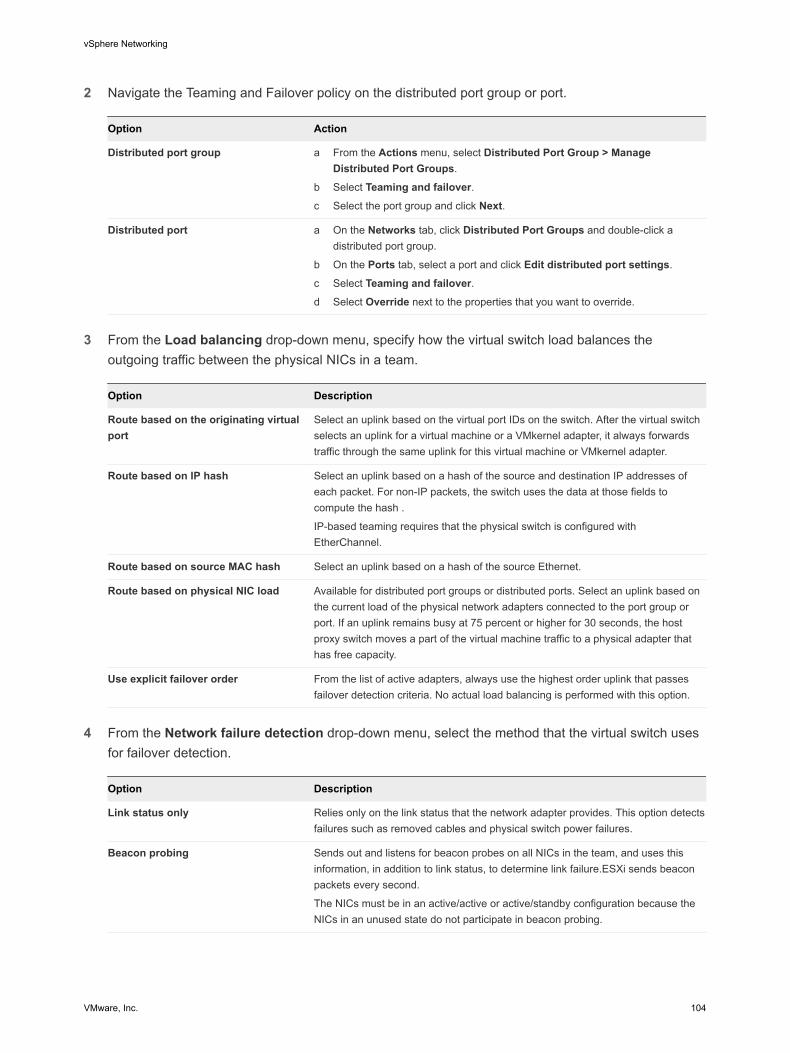
2 Navigate the Teaming and Failover policy on the distributed port group or port.
Option Action
Distributed port group a From the Actions menu, select Distributed Port Group > Manage Distributed Port Groups.
b Select Teaming and failover.c Select the port group and click Next.
Distributed port a On the Networks tab, click Distributed Port Groups and double-click a distributed port group.
b On the Ports tab, select a port and click Edit distributed port settings.
c Select Teaming and failover.d Select Override next to the properties that you want to override.
3 From the Load balancing drop-down menu, specify how the virtual switch load balances the
outgoing traffic between the physical NICs in a team.
Option Description
Route based on the originating virtual port
Select an uplink based on the virtual port IDs on the switch. After the virtual switch selects an uplink for a virtual machine or a VMkernel adapter, it always forwards traffic through the same uplink for this virtual machine or VMkernel adapter.
Route based on IP hash Select an uplink based on a hash of the source and destination IP addresses of each packet. For non-IP packets, the switch uses the data at those fields to compute the hash .
IP-based teaming requires that the physical switch is configured with EtherChannel.
Route based on source MAC hash Select an uplink based on a hash of the source Ethernet.
Route based on physical NIC load Available for distributed port groups or distributed ports. Select an uplink based on the current load of the physical network adapters connected to the port group or port. If an uplink remains busy at 75 percent or higher for 30 seconds, the host proxy switch moves a part of the virtual machine traffic to a physical adapter that has free capacity.
Use explicit failover order From the list of active adapters, always use the highest order uplink that passes failover detection criteria. No actual load balancing is performed with this option.
4 From the Network failure detection drop-down menu, select the method that the virtual switch uses
for failover detection.
Option Description
Link status only Relies only on the link status that the network adapter provides. This option detects failures such as removed cables and physical switch power failures.
Beacon probing Sends out and listens for beacon probes on all NICs in the team, and uses this information, in addition to link status, to determine link failure.ESXi sends beacon packets every second.
The NICs must be in an active/active or active/standby configuration because the NICs in an unused state do not participate in beacon probing.
vSphere Networking
VMware, Inc. 104
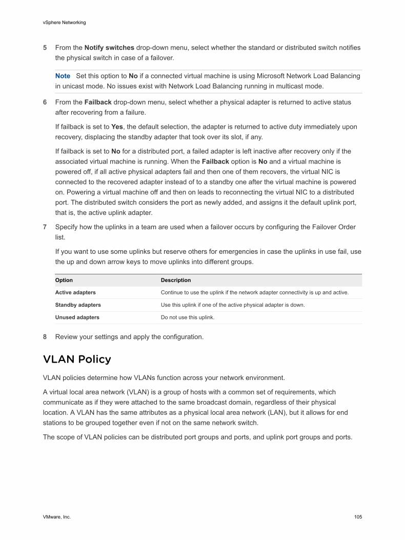
5 From the Notify switches drop-down menu, select whether the standard or distributed switch notifies the physical switch in case of a failover.
Note Set this option to No if a connected virtual machine is using Microsoft Network Load Balancing in unicast mode. No issues exist with Network Load Balancing running in multicast mode.
6 From the Failback drop-down menu, select whether a physical adapter is returned to active status after recovering from a failure.
If failback is set to Yes, the default selection, the adapter is returned to active duty immediately upon recovery, displacing the standby adapter that took over its slot, if any.
If failback is set to No for a distributed port, a failed adapter is left inactive after recovery only if the associated virtual machine is running. When the Failback option is No and a virtual machine is powered off, if all active physical adapters fail and then one of them recovers, the virtual NIC is connected to the recovered adapter instead of to a standby one after the virtual machine is powered on. Powering a virtual machine off and then on leads to reconnecting the virtual NIC to a distributed port. The distributed switch considers the port as newly added, and assigns it the default uplink port, that is, the active uplink adapter.
7 Specify how the uplinks in a team are used when a failover occurs by configuring the Failover Order list.
If you want to use some uplinks but reserve others for emergencies in case the uplinks in use fail, use the up and down arrow keys to move uplinks into different groups.
Option Description
Active adapters Continue to use the uplink if the network adapter connectivity is up and active.
Standby adapters Use this uplink if one of the active physical adapter is down.
Unused adapters Do not use this uplink.
8 Review your settings and apply the configuration.
VLAN PolicyVLAN policies determine how VLANs function across your network environment.
A virtual local area network (VLAN) is a group of hosts with a common set of requirements, which communicate as if they were attached to the same broadcast domain, regardless of their physical location. A VLAN has the same attributes as a physical local area network (LAN), but it allows for end stations to be grouped together even if not on the same network switch.
The scope of VLAN policies can be distributed port groups and ports, and uplink port groups and ports.
vSphere Networking
VMware, Inc. 105
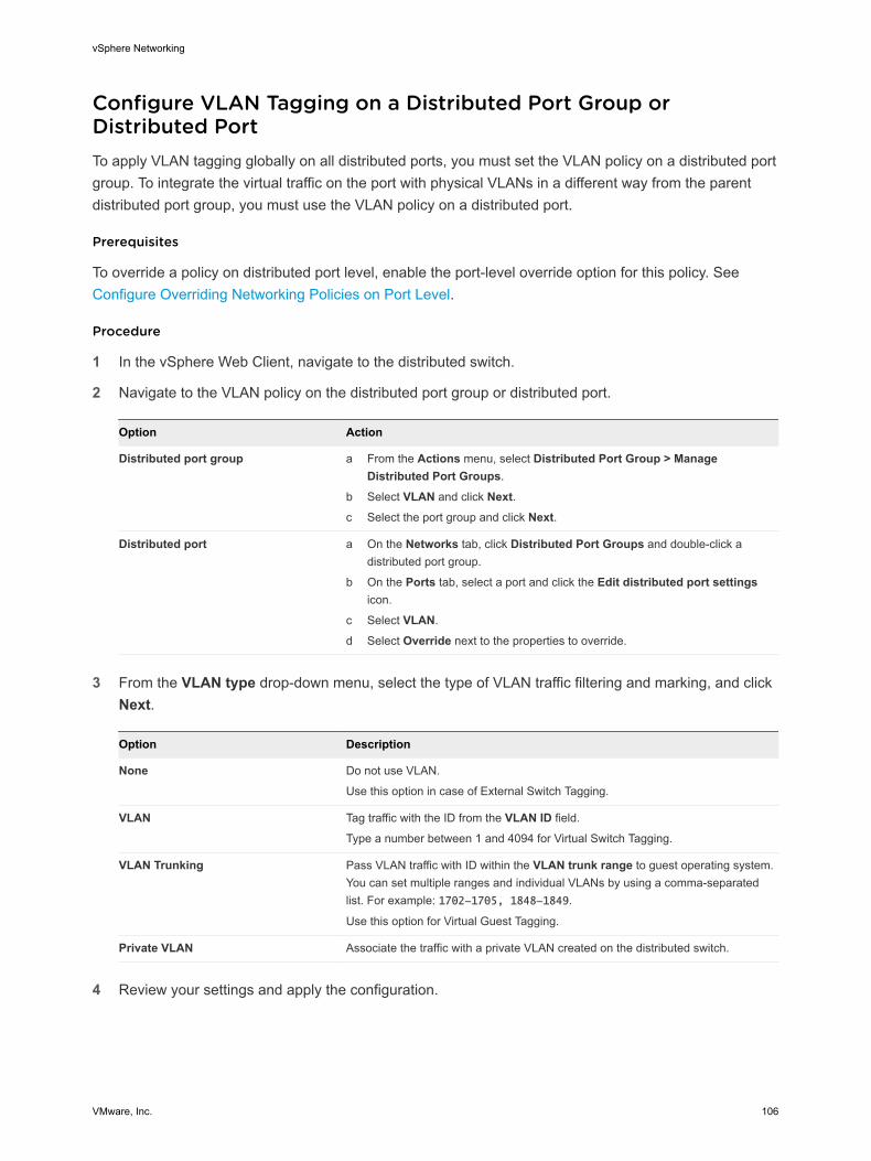
Configure VLAN Tagging on a Distributed Port Group or Distributed PortTo apply VLAN tagging globally on all distributed ports, you must set the VLAN policy on a distributed port group. To integrate the virtual traffic on the port with physical VLANs in a different way from the parent distributed port group, you must use the VLAN policy on a distributed port.
Prerequisites
To override a policy on distributed port level, enable the port-level override option for this policy. See Configure Overriding Networking Policies on Port Level.
Procedure
1 In the vSphere Web Client, navigate to the distributed switch.
2 Navigate to the VLAN policy on the distributed port group or distributed port.
Option Action
Distributed port group a From the Actions menu, select Distributed Port Group > Manage Distributed Port Groups.
b Select VLAN and click Next.c Select the port group and click Next.
Distributed port a On the Networks tab, click Distributed Port Groups and double-click a distributed port group.
b On the Ports tab, select a port and click the Edit distributed port settings icon.
c Select VLAN.
d Select Override next to the properties to override.
3 From the VLAN type drop-down menu, select the type of VLAN traffic filtering and marking, and click Next.
Option Description
None Do not use VLAN.
Use this option in case of External Switch Tagging.
VLAN Tag traffic with the ID from the VLAN ID field.
Type a number between 1 and 4094 for Virtual Switch Tagging.
VLAN Trunking Pass VLAN traffic with ID within the VLAN trunk range to guest operating system. You can set multiple ranges and individual VLANs by using a comma-separated list. For example: 1702-1705, 1848-1849.
Use this option for Virtual Guest Tagging.
Private VLAN Associate the traffic with a private VLAN created on the distributed switch.
4 Review your settings and apply the configuration.
vSphere Networking
VMware, Inc. 106
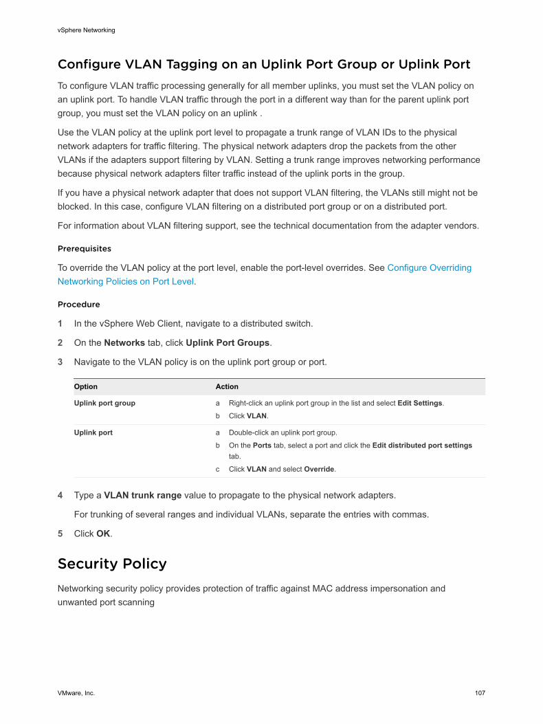
Configure VLAN Tagging on an Uplink Port Group or Uplink PortTo configure VLAN traffic processing generally for all member uplinks, you must set the VLAN policy on an uplink port. To handle VLAN traffic through the port in a different way than for the parent uplink port group, you must set the VLAN policy on an uplink .
Use the VLAN policy at the uplink port level to propagate a trunk range of VLAN IDs to the physical network adapters for traffic filtering. The physical network adapters drop the packets from the other VLANs if the adapters support filtering by VLAN. Setting a trunk range improves networking performance because physical network adapters filter traffic instead of the uplink ports in the group.
If you have a physical network adapter that does not support VLAN filtering, the VLANs still might not be blocked. In this case, configure VLAN filtering on a distributed port group or on a distributed port.
For information about VLAN filtering support, see the technical documentation from the adapter vendors.
Prerequisites
To override the VLAN policy at the port level, enable the port-level overrides. See Configure Overriding Networking Policies on Port Level.
Procedure
1 In the vSphere Web Client, navigate to a distributed switch.
2 On the Networks tab, click Uplink Port Groups.
3 Navigate to the VLAN policy is on the uplink port group or port.
Option Action
Uplink port group a Right-click an uplink port group in the list and select Edit Settings.
b Click VLAN.
Uplink port a Double-click an uplink port group.
b On the Ports tab, select a port and click the Edit distributed port settings tab.
c Click VLAN and select Override.
4 Type a VLAN trunk range value to propagate to the physical network adapters.
For trunking of several ranges and individual VLANs, separate the entries with commas.
5 Click OK.
Security PolicyNetworking security policy provides protection of traffic against MAC address impersonation and unwanted port scanning
vSphere Networking
VMware, Inc. 107
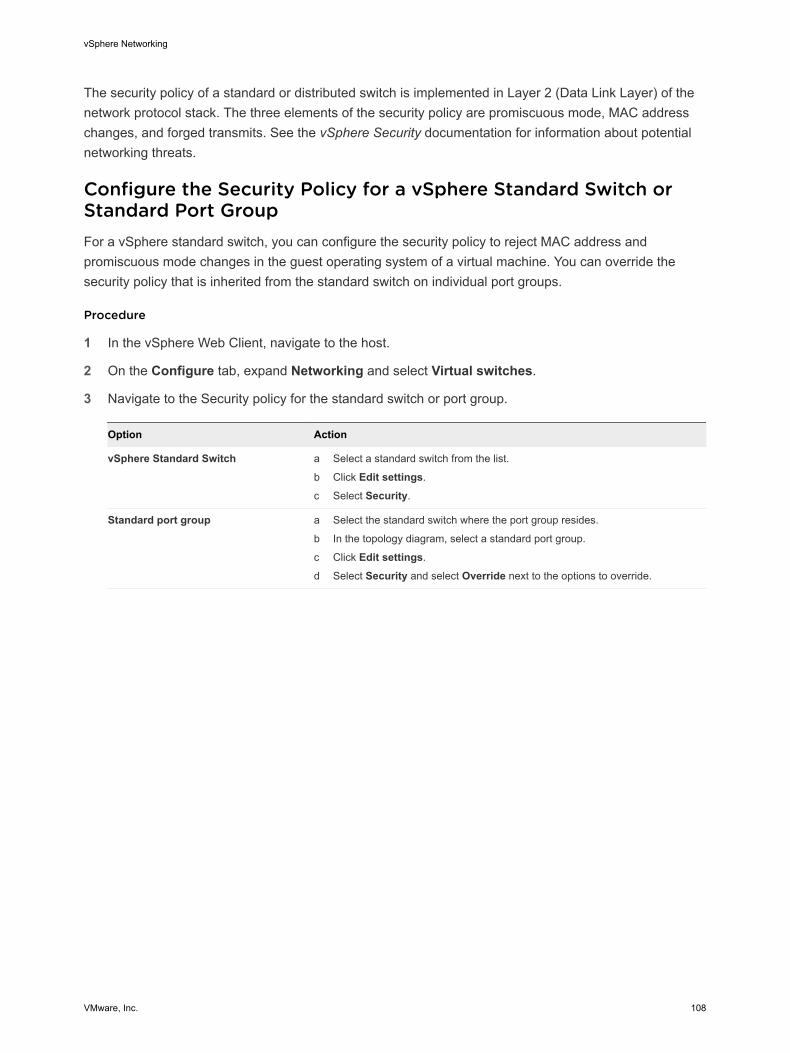
The security policy of a standard or distributed switch is implemented in Layer 2 (Data Link Layer) of the network protocol stack. The three elements of the security policy are promiscuous mode, MAC address changes, and forged transmits. See the vSphere Security documentation for information about potential networking threats.
Configure the Security Policy for a vSphere Standard Switch or Standard Port GroupFor a vSphere standard switch, you can configure the security policy to reject MAC address and promiscuous mode changes in the guest operating system of a virtual machine. You can override the security policy that is inherited from the standard switch on individual port groups.
Procedure
1 In the vSphere Web Client, navigate to the host.
2 On the Configure tab, expand Networking and select Virtual switches.
3 Navigate to the Security policy for the standard switch or port group.
Option Action
vSphere Standard Switch a Select a standard switch from the list.
b Click Edit settings.
c Select Security.
Standard port group a Select the standard switch where the port group resides.
b In the topology diagram, select a standard port group.
c Click Edit settings.
d Select Security and select Override next to the options to override.
vSphere Networking
VMware, Inc. 108
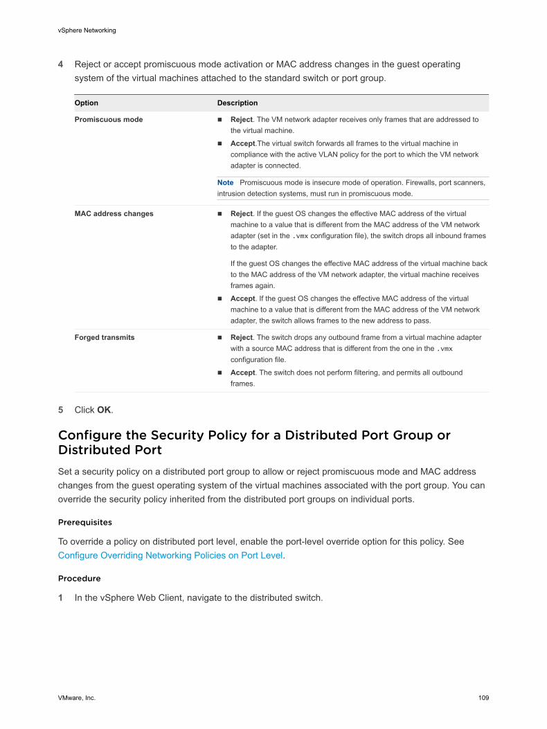
4 Reject or accept promiscuous mode activation or MAC address changes in the guest operating system of the virtual machines attached to the standard switch or port group.
Option Description
Promiscuous mode n Reject. The VM network adapter receives only frames that are addressed to the virtual machine.
n Accept.The virtual switch forwards all frames to the virtual machine in compliance with the active VLAN policy for the port to which the VM network adapter is connected.
Note Promiscuous mode is insecure mode of operation. Firewalls, port scanners, intrusion detection systems, must run in promiscuous mode.
MAC address changes n Reject. If the guest OS changes the effective MAC address of the virtual machine to a value that is different from the MAC address of the VM network adapter (set in the .vmx configuration file), the switch drops all inbound frames to the adapter.
If the guest OS changes the effective MAC address of the virtual machine back to the MAC address of the VM network adapter, the virtual machine receives frames again.
n Accept. If the guest OS changes the effective MAC address of the virtual machine to a value that is different from the MAC address of the VM network adapter, the switch allows frames to the new address to pass.
Forged transmits n Reject. The switch drops any outbound frame from a virtual machine adapter with a source MAC address that is different from the one in the .vmx configuration file.
n Accept. The switch does not perform filtering, and permits all outbound frames.
5 Click OK.
Configure the Security Policy for a Distributed Port Group or Distributed PortSet a security policy on a distributed port group to allow or reject promiscuous mode and MAC address changes from the guest operating system of the virtual machines associated with the port group. You can override the security policy inherited from the distributed port groups on individual ports.
Prerequisites
To override a policy on distributed port level, enable the port-level override option for this policy. See Configure Overriding Networking Policies on Port Level.
Procedure
1 In the vSphere Web Client, navigate to the distributed switch.
vSphere Networking
VMware, Inc. 109
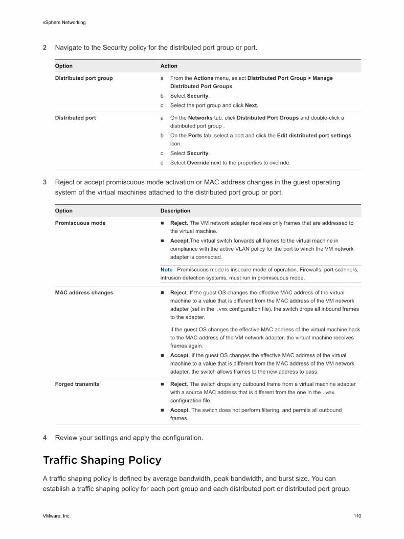
2 Navigate to the Security policy for the distributed port group or port.
Option Action
Distributed port group a From the Actions menu, select Distributed Port Group > Manage Distributed Port Groups.
b Select Security.
c Select the port group and click Next.
Distributed port a On the Networks tab, click Distributed Port Groups and double-click a distributed port group .
b On the Ports tab, select a port and click the Edit distributed port settings icon.
c Select Security.
d Select Override next to the properties to override.
3 Reject or accept promiscuous mode activation or MAC address changes in the guest operating system of the virtual machines attached to the distributed port group or port.
Option Description
Promiscuous mode n Reject. The VM network adapter receives only frames that are addressed to the virtual machine.
n Accept.The virtual switch forwards all frames to the virtual machine in compliance with the active VLAN policy for the port to which the VM network adapter is connected.
Note Promiscuous mode is insecure mode of operation. Firewalls, port scanners, intrusion detection systems, must run in promiscuous mode.
MAC address changes n Reject. If the guest OS changes the effective MAC address of the virtual machine to a value that is different from the MAC address of the VM network adapter (set in the .vmx configuration file), the switch drops all inbound frames to the adapter.
If the guest OS changes the effective MAC address of the virtual machine back to the MAC address of the VM network adapter, the virtual machine receives frames again.
n Accept. If the guest OS changes the effective MAC address of the virtual machine to a value that is different from the MAC address of the VM network adapter, the switch allows frames to the new address to pass.
Forged transmits n Reject. The switch drops any outbound frame from a virtual machine adapter with a source MAC address that is different from the one in the .vmx configuration file.
n Accept. The switch does not perform filtering, and permits all outbound frames.
4 Review your settings and apply the configuration.
Traffic Shaping PolicyA traffic shaping policy is defined by average bandwidth, peak bandwidth, and burst size. You can establish a traffic shaping policy for each port group and each distributed port or distributed port group.
vSphere Networking
VMware, Inc. 110
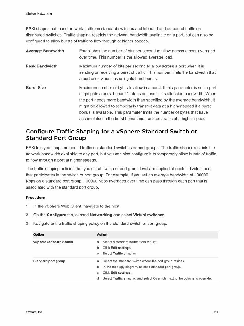
ESXi shapes outbound network traffic on standard switches and inbound and outbound traffic on distributed switches. Traffic shaping restricts the network bandwidth available on a port, but can also be configured to allow bursts of traffic to flow through at higher speeds.
Average Bandwidth Establishes the number of bits per second to allow across a port, averaged over time. This number is the allowed average load.
Peak Bandwidth Maximum number of bits per second to allow across a port when it is sending or receiving a burst of traffic. This number limits the bandwidth that a port uses when it is using its burst bonus.
Burst Size Maximum number of bytes to allow in a burst. If this parameter is set, a port might gain a burst bonus if it does not use all its allocated bandwidth. When the port needs more bandwidth than specified by the average bandwidth, it might be allowed to temporarily transmit data at a higher speed if a burst bonus is available. This parameter limits the number of bytes that have accumulated in the burst bonus and transfers traffic at a higher speed.
Configure Traffic Shaping for a vSphere Standard Switch or Standard Port GroupESXi lets you shape outbound traffic on standard switches or port groups. The traffic shaper restricts the network bandwidth available to any port, but you can also configure it to temporarily allow bursts of traffic to flow through a port at higher speeds.
The traffic shaping policies that you set at switch or port group level are applied at each individual port that participates in the switch or port group. For example, if you set an average bandwidth of 100000 Kbps on a standard port group, 100000 Kbps averaged over time can pass through each port that is associated with the standard port group.
Procedure
1 In the vSphere Web Client, navigate to the host.
2 On the Configure tab, expand Networking and select Virtual switches.
3 Navigate to the traffic shaping policy on the standard switch or port group.
Option Action
vSphere Standard Switch a Select a standard switch from the list.
b Click Edit settings.
c Select Traffic shaping.
Standard port group a Select the standard switch where the port group resides.
b In the topology diagram, select a standard port group.
c Click Edit settings.
d Select Traffic shaping and select Override next to the options to override.
vSphere Networking
VMware, Inc. 111
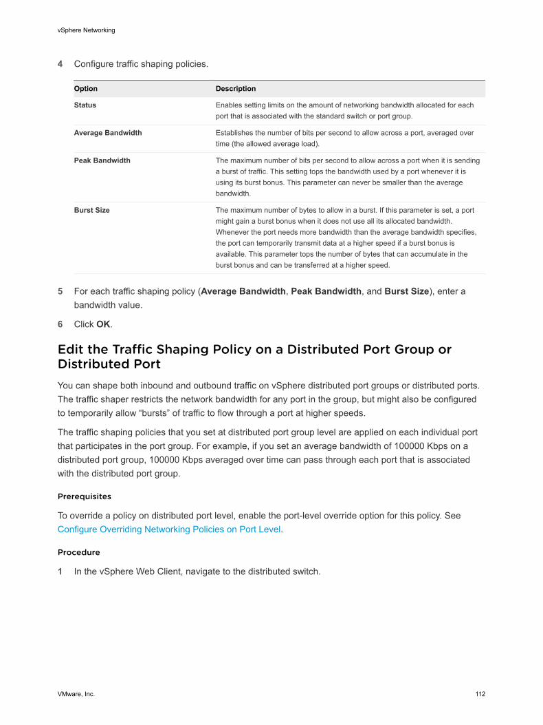
4 Configure traffic shaping policies.
Option Description
Status Enables setting limits on the amount of networking bandwidth allocated for each port that is associated with the standard switch or port group.
Average Bandwidth Establishes the number of bits per second to allow across a port, averaged over time (the allowed average load).
Peak Bandwidth The maximum number of bits per second to allow across a port when it is sending a burst of traffic. This setting tops the bandwidth used by a port whenever it is using its burst bonus. This parameter can never be smaller than the average bandwidth.
Burst Size The maximum number of bytes to allow in a burst. If this parameter is set, a port might gain a burst bonus when it does not use all its allocated bandwidth. Whenever the port needs more bandwidth than the average bandwidth specifies, the port can temporarily transmit data at a higher speed if a burst bonus is available. This parameter tops the number of bytes that can accumulate in the burst bonus and can be transferred at a higher speed.
5 For each traffic shaping policy (Average Bandwidth, Peak Bandwidth, and Burst Size), enter a
bandwidth value.
6 Click OK.
Edit the Traffic Shaping Policy on a Distributed Port Group or Distributed PortYou can shape both inbound and outbound traffic on vSphere distributed port groups or distributed ports. The traffic shaper restricts the network bandwidth for any port in the group, but might also be configured to temporarily allow “bursts” of traffic to flow through a port at higher speeds.
The traffic shaping policies that you set at distributed port group level are applied on each individual port that participates in the port group. For example, if you set an average bandwidth of 100000 Kbps on a distributed port group, 100000 Kbps averaged over time can pass through each port that is associated with the distributed port group.
Prerequisites
To override a policy on distributed port level, enable the port-level override option for this policy. See Configure Overriding Networking Policies on Port Level.
Procedure
1 In the vSphere Web Client, navigate to the distributed switch.
vSphere Networking
VMware, Inc. 112
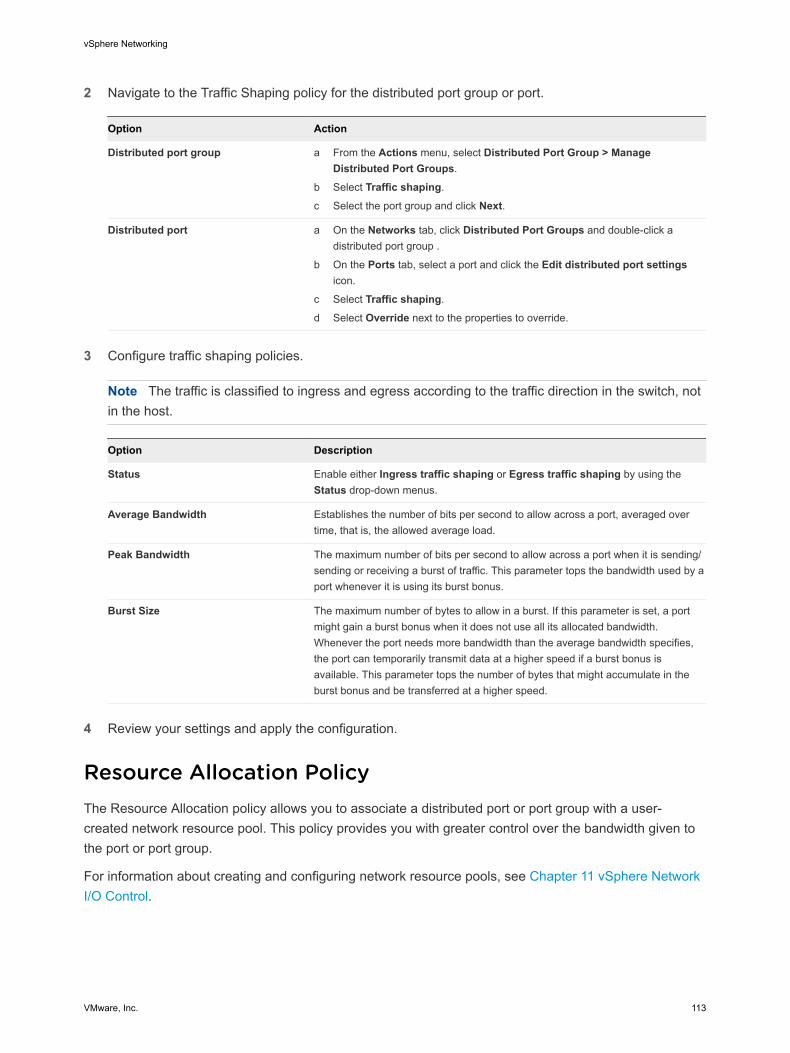
2 Navigate to the Traffic Shaping policy for the distributed port group or port.
Option Action
Distributed port group a From the Actions menu, select Distributed Port Group > Manage Distributed Port Groups.
b Select Traffic shaping.
c Select the port group and click Next.
Distributed port a On the Networks tab, click Distributed Port Groups and double-click a distributed port group .
b On the Ports tab, select a port and click the Edit distributed port settings icon.
c Select Traffic shaping.
d Select Override next to the properties to override.
3 Configure traffic shaping policies.
Note The traffic is classified to ingress and egress according to the traffic direction in the switch, not in the host.
Option Description
Status Enable either Ingress traffic shaping or Egress traffic shaping by using the Status drop-down menus.
Average Bandwidth Establishes the number of bits per second to allow across a port, averaged over time, that is, the allowed average load.
Peak Bandwidth The maximum number of bits per second to allow across a port when it is sending/sending or receiving a burst of traffic. This parameter tops the bandwidth used by a port whenever it is using its burst bonus.
Burst Size The maximum number of bytes to allow in a burst. If this parameter is set, a port might gain a burst bonus when it does not use all its allocated bandwidth. Whenever the port needs more bandwidth than the average bandwidth specifies, the port can temporarily transmit data at a higher speed if a burst bonus is available. This parameter tops the number of bytes that might accumulate in the burst bonus and be transferred at a higher speed.
4 Review your settings and apply the configuration.
Resource Allocation PolicyThe Resource Allocation policy allows you to associate a distributed port or port group with a user-created network resource pool. This policy provides you with greater control over the bandwidth given to the port or port group.
For information about creating and configuring network resource pools, see Chapter 11 vSphere Network I/O Control.
vSphere Networking
VMware, Inc. 113
Edit the Resource Allocation Policy on a Distributed Port GroupAssociate a distributed port group with a network resource pool to give you greater control over the bandwidth that is given to the distributed port group.
Prerequisites
n Enable Network I/O Control on the distributed switch. See Enable Network I/O Control on a vSphere Distributed Switch.
n Create and configure network resource pools. See Create a Network Resource Pool.
Procedure
1 In the vSphere Web Client, navigate to the distributed switch.
2 Right-click the distributed switch in the navigator and select Distributed Port Groups > Manage Distributed Port Groups.
3 Select the Resource allocation check box and click Next.
4 Select the distributed port group to configure and click Next.
5 Add or remove the distributed port group from the network resource pool and click Next.
n To add the distributed port group, select a user-defined resource pool from the Network resource pool drop-down menu.
n To remove the distributed port group, select default from the Network resource pool drop-down menu.
6 Review your settings in the Ready to complete section and click Finish.
Use the Back button to change any settings.
Monitoring PolicyThe monitoring policy enables or disables NetFlow monitoring on a distributed port or port group.
NetFlow settings are configured at the vSphere distributed switch level. See Configure the NetFlow Settings of a vSphere Distributed Switch.
Enable or Disable NetFlow Monitoring on a Distributed Port Group or Distributed PortYou can enable NetFlow to monitor IP packets that are passing through the ports of a distributed port group or through individual distributed ports.
You configure the NetFlow settings on the vSphere Distributed Switch. See Configure the NetFlow Settings of a vSphere Distributed Switch
vSphere Networking
VMware, Inc. 114
Prerequisites
To override a policy on distributed port level, enable the port-level override option for this policy. See Configure Overriding Networking Policies on Port Level.
Procedure
1 In the vSphere Web Client, navigate to the distributed switch.
2 Navigate to the monitoring policy for the distributed port group or distributed port.
Option Action
Distributed port group a From the Actions menu, select Distributed Port Group > Manage Distributed Port Groups.
b Select Monitoring.
c Select the port group and click Next.
Distributed port a On the Networks tab, click Distributed Port Groups and double-click a distributed port group .
b On the Ports tab, select a port and click the Edit distributed port settings icon.
c Select Monitoring.
d Select Override next to the properties to override.
3 From the NetFlow drop-down menu, enable or disable NetFlow and click Next.
4 Verify your settings and apply the configuration.
Traffic Filtering and Marking PolicyIn a vSphere distributed switch, by using the traffic filtering and marking policy, you can protect the virtual network from unwanted traffic and security attacks or apply a QoS tag to a certain type of traffic.
The traffic filtering and marking policy represents an ordered set of network traffic rules for security and for QoS tagging of the data flow through the ports of a distributed switch. In general, a rule consists of a qualifier for traffic, and of an action for restricting or prioritizing the matching traffic.
The vSphere distributed switch applies rules on traffic at different places in the data stream. The distributed switch applies traffic filter rules on the data path between the virtual machine network adapter and distributed port, or between the uplink port and physical network adapter for rules on uplinks.
vSphere Networking
VMware, Inc. 115
Traffic Filtering and Marking on a Distributed Port Group or Uplink Port GroupSet traffic rules at the level of distributed port groups or of uplink port groups to introduce filtering and priority tagging for traffic access over virtual machines, VMkernel adapters, or physical adapters.
n Enable Traffic Filtering and Marking on a Distributed Port Group or Uplink Port Group
Enable the traffic filtering and marking policy on a port group if you want to configure traffic security and marking on all virtual machine network adapters or uplink adapters that are participating in the group.
n Mark Traffic on a Distributed Port Group or Uplink Port Group
Assign priority tags to traffic, such as VoIP and streaming video, that has higher networking requirements for bandwidth, low latency, and so on. You can mark the traffic with a CoS tag in Layer 2 of the network protocol stack or with a DSCP tag in Layer 3.
n Filter Traffic on a Distributed Port Group or Uplink Port Group
Allow or stop traffic for securing the data that flows through the ports of a distributed port group or uplink port group.
n Working with Network Traffic Rules on a Distributed Port Group or Uplink Port Group
Define traffic rules in a distributed port group or uplink port group to introduce a policy for processing traffic related to virtual machines or to physical adapters. You can filter specific traffic or describe its QoS demands.
n Disable Traffic Filtering and Marking on a Distributed Port Group or Uplink Port Group
Let traffic flow to virtual machines or physical adapters without additional control related to security or QoS by disabling the traffic filtering and marking policy.
Enable Traffic Filtering and Marking on a Distributed Port Group or Uplink Port GroupEnable the traffic filtering and marking policy on a port group if you want to configure traffic security and marking on all virtual machine network adapters or uplink adapters that are participating in the group.
Note You can disable the traffic filtering and marking policy on a particular port to avoid processing the traffic flowing through the port. See Disable Traffic Filtering and Marking on a Distributed Port or Uplink Port.
Procedure
1 Locate a distributed port group or an uplink port group in the vSphere Web Client.
a Select a distributed switch and click the Networks tab.
b Click Distributed Port Groups to see the list of distributed port groups, or click Uplink Port Groups to see the list of uplink port groups.
2 Right-click the port group and select Edit Settings.
vSphere Networking
VMware, Inc. 116
3 Select Traffic filtering and marking.
4 From the Status drop-down menu, select Enabled.
5 Click OK.
What to do next
Set up traffic marking or filtering on the data that is flowing through the ports of the distributed port group or through the uplink port group. See Mark Traffic on a Distributed Port Group or Uplink Port Group and Filter Traffic on a Distributed Port Group or Uplink Port Group.
Mark Traffic on a Distributed Port Group or Uplink Port GroupAssign priority tags to traffic, such as VoIP and streaming video, that has higher networking requirements for bandwidth, low latency, and so on. You can mark the traffic with a CoS tag in Layer 2 of the network protocol stack or with a DSCP tag in Layer 3.
Priority tagging is a mechanism to mark traffic that has higher QoS demands. In this way, the network can recognize different classes of traffic. The network devices can handle the traffic from each class according to its priority and requirements.
You can also re-tag traffic to either raise or lower the importance of the flow. By using a low QoS tag, you can restrict data tagged in a guest operating system.
Procedure
1 Locate a distributed port group or an uplink port group in the vSphere Web Client.
a Select a distributed switch and click the Networks tab.
b Click Distributed Port Groups to see the list of distributed port groups, or click Uplink Port Groups to see the list of uplink port groups.
2 Right-click the port group and select Edit Settings.
3 Select Traffic filtering and marking.
4 If traffic filtering and marking is disabled, enable it from the Status drop-down menu.
5 Click New to create a new rule, or select a rule and click Edit to edit it.
6 In the network traffic rule dialog box, select the Tag option from the Action drop-down menu.
7 Set the priority tag for the traffic within the scope of the rule.
Option Description
CoS value Mark the traffic matching the rule with a CoS priority tag in network Layer 2. Select Update CoS tag and type a value from 0 to 7.
DSCP value Mark the traffic associated with the rule with a DSCP tag in network Layer 3. Select Update DSCP value and type a value from 0 to 63.
vSphere Networking
VMware, Inc. 117
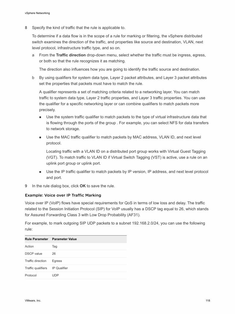
8 Specify the kind of traffic that the rule is applicable to.
To determine if a data flow is in the scope of a rule for marking or filtering, the vSphere distributed switch examines the direction of the traffic, and properties like source and destination, VLAN, next level protocol, infrastructure traffic type, and so on.
a From the Traffic direction drop-down menu, select whether the traffic must be ingress, egress, or both so that the rule recognizes it as matching.
The direction also influences how you are going to identify the traffic source and destination.
b By using qualifiers for system data type, Layer 2 packet attributes, and Layer 3 packet attributes set the properties that packets must have to match the rule.
A qualifier represents a set of matching criteria related to a networking layer. You can match traffic to system data type, Layer 2 traffic properties, and Layer 3 traffic properties. You can use the qualifier for a specific networking layer or can combine qualifiers to match packets more precisely.
n Use the system traffic qualifier to match packets to the type of virtual infrastructure data that is flowing through the ports of the group . For example, you can select NFS for data transfers to network storage.
n Use the MAC traffic qualifier to match packets by MAC address, VLAN ID, and next level protocol.
Locating traffic with a VLAN ID on a distributed port group works with Virtual Guest Tagging (VGT). To match traffic to VLAN ID if Virtual Switch Tagging (VST) is active, use a rule on an uplink port group or uplink port.
n Use the IP traffic qualifier to match packets by IP version, IP address, and next level protocol and port.
9 In the rule dialog box, click OK to save the rule.
Example: Voice over IP Traffic Marking
Voice over IP (VoIP) flows have special requirements for QoS in terms of low loss and delay. The traffic related to the Session Initiation Protocol (SIP) for VoIP usually has a DSCP tag equal to 26, which stands for Assured Forwarding Class 3 with Low Drop Probability (AF31).
For example, to mark outgoing SIP UDP packets to a subnet 192.168.2.0/24, you can use the following rule:
Rule Parameter Parameter Value
Action Tag
DSCP value 26
Traffic direction Egress
Traffic qualifiers IP Qualifier
Protocol UDP
vSphere Networking
VMware, Inc. 118
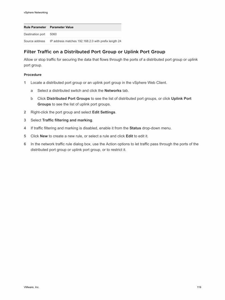
Rule Parameter Parameter Value
Destination port 5060
Source address IP address matches 192.168.2.0 with prefix length 24
Filter Traffic on a Distributed Port Group or Uplink Port GroupAllow or stop traffic for securing the data that flows through the ports of a distributed port group or uplink port group.
Procedure
1 Locate a distributed port group or an uplink port group in the vSphere Web Client.
a Select a distributed switch and click the Networks tab.
b Click Distributed Port Groups to see the list of distributed port groups, or click Uplink Port Groups to see the list of uplink port groups.
2 Right-click the port group and select Edit Settings.
3 Select Traffic filtering and marking.
4 If traffic filtering and marking is disabled, enable it from the Status drop-down menu.
5 Click New to create a new rule, or select a rule and click Edit to edit it.
6 In the network traffic rule dialog box, use the Action options to let traffic pass through the ports of the distributed port group or uplink port group, or to restrict it.
vSphere Networking
VMware, Inc. 119
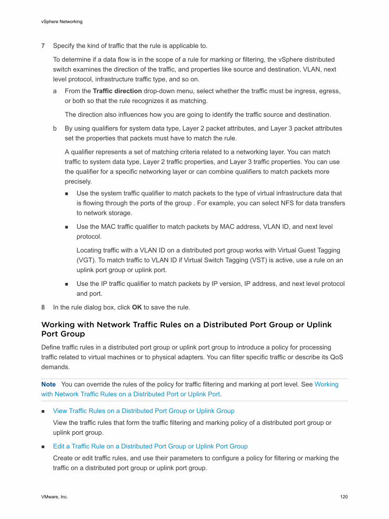
7 Specify the kind of traffic that the rule is applicable to.
To determine if a data flow is in the scope of a rule for marking or filtering, the vSphere distributed switch examines the direction of the traffic, and properties like source and destination, VLAN, next level protocol, infrastructure traffic type, and so on.
a From the Traffic direction drop-down menu, select whether the traffic must be ingress, egress, or both so that the rule recognizes it as matching.
The direction also influences how you are going to identify the traffic source and destination.
b By using qualifiers for system data type, Layer 2 packet attributes, and Layer 3 packet attributes set the properties that packets must have to match the rule.
A qualifier represents a set of matching criteria related to a networking layer. You can match traffic to system data type, Layer 2 traffic properties, and Layer 3 traffic properties. You can use the qualifier for a specific networking layer or can combine qualifiers to match packets more precisely.
n Use the system traffic qualifier to match packets to the type of virtual infrastructure data that is flowing through the ports of the group . For example, you can select NFS for data transfers to network storage.
n Use the MAC traffic qualifier to match packets by MAC address, VLAN ID, and next level protocol.
Locating traffic with a VLAN ID on a distributed port group works with Virtual Guest Tagging (VGT). To match traffic to VLAN ID if Virtual Switch Tagging (VST) is active, use a rule on an uplink port group or uplink port.
n Use the IP traffic qualifier to match packets by IP version, IP address, and next level protocol and port.
8 In the rule dialog box, click OK to save the rule.
Working with Network Traffic Rules on a Distributed Port Group or Uplink Port GroupDefine traffic rules in a distributed port group or uplink port group to introduce a policy for processing traffic related to virtual machines or to physical adapters. You can filter specific traffic or describe its QoS demands.
Note You can override the rules of the policy for traffic filtering and marking at port level. See Working with Network Traffic Rules on a Distributed Port or Uplink Port.
n View Traffic Rules on a Distributed Port Group or Uplink Group
View the traffic rules that form the traffic filtering and marking policy of a distributed port group or uplink port group.
n Edit a Traffic Rule on a Distributed Port Group or Uplink Port Group
Create or edit traffic rules, and use their parameters to configure a policy for filtering or marking the traffic on a distributed port group or uplink port group.
vSphere Networking
VMware, Inc. 120

n Change Rule Priorities on a Distributed Port Group or Uplink Port Group
Reorder the rules that form the traffic filtering and marking policy of a distributed port group or uplink port group to change the sequence of actions for processing traffic.
n Delete a Traffic Rule on a Distributed Port Group or Uplink Port Group
Delete a traffic rule on a distributed port group or uplink port group to stop processing packets flowing to virtual machines or physical adapters in a specific way.
View Traffic Rules on a Distributed Port Group or Uplink Group
View the traffic rules that form the traffic filtering and marking policy of a distributed port group or uplink port group.
Procedure
1 Locate a distributed port group or an uplink port group in the vSphere Web Client.
a Select a distributed switch and click the Networks tab.
b Click Distributed Port Groups to see the list of distributed port groups, or click Uplink Port Groups to see the list of uplink port groups.
2 Right-click the port group and select Edit Settings.
3 Select Traffic filtering and marking.
4 If traffic filtering and marking is disabled, enable it from the Status drop-down menu.
5 Examine Action to see if the rule filters traffic (Allow or Deny) or marks traffic (Tag) with special QoS demands.
6 From the upper list, select the rule for which you want to view the criteria for locating traffic.
The traffic qualifying parameters of the rule appear in the Traffic Qualifiers list.
Edit a Traffic Rule on a Distributed Port Group or Uplink Port Group
Create or edit traffic rules, and use their parameters to configure a policy for filtering or marking the traffic on a distributed port group or uplink port group.
Procedure
1 Locate a distributed port group or an uplink port group in the vSphere Web Client.
a Select a distributed switch and click the Networks tab.
b Click Distributed Port Groups to see the list of distributed port groups, or click Uplink Port Groups to see the list of uplink port groups.
2 Right-click the port group and select Edit Settings.
3 Select Traffic filtering and marking.
4 If traffic filtering and marking is disabled, enable it from the Status drop-down menu.
5 Click New to create a new rule, or select a rule and click Edit to edit it.
vSphere Networking
VMware, Inc. 121
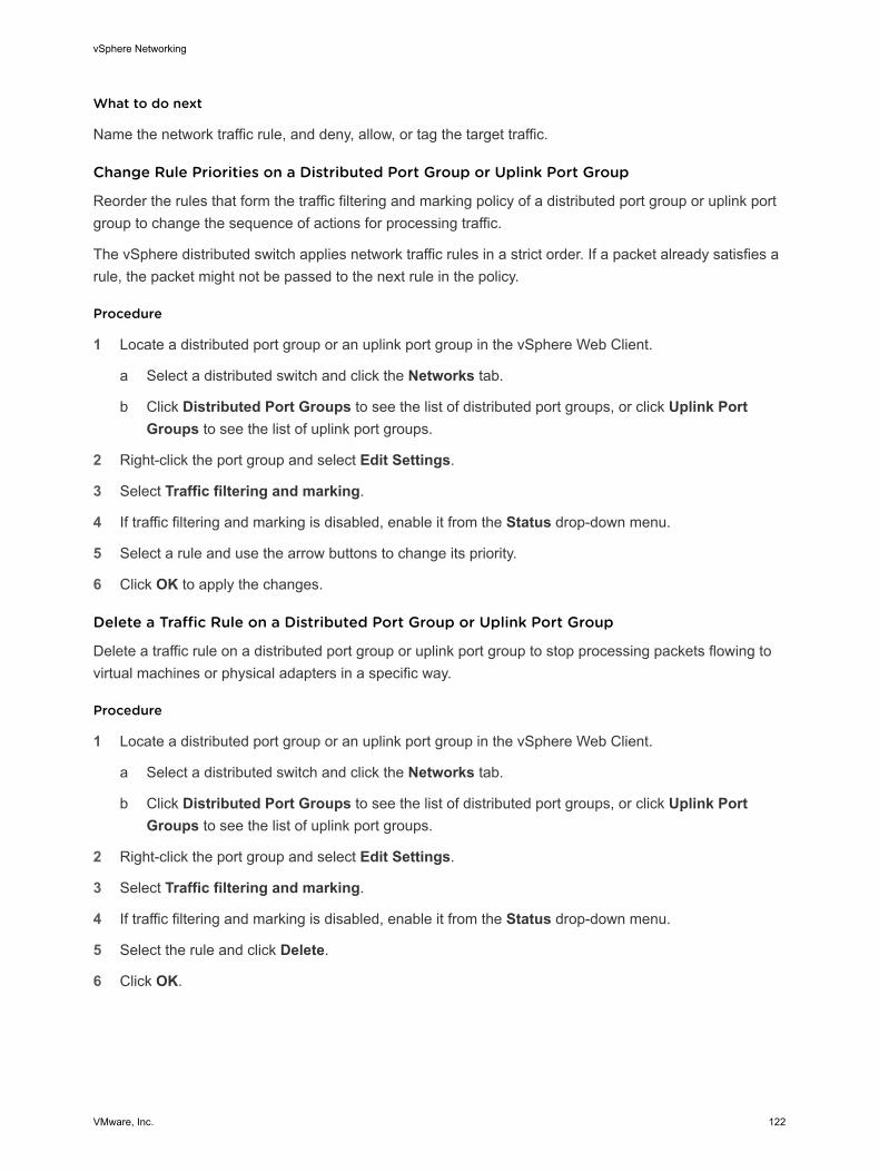
What to do next
Name the network traffic rule, and deny, allow, or tag the target traffic.
Change Rule Priorities on a Distributed Port Group or Uplink Port Group
Reorder the rules that form the traffic filtering and marking policy of a distributed port group or uplink port group to change the sequence of actions for processing traffic.
The vSphere distributed switch applies network traffic rules in a strict order. If a packet already satisfies a rule, the packet might not be passed to the next rule in the policy.
Procedure
1 Locate a distributed port group or an uplink port group in the vSphere Web Client.
a Select a distributed switch and click the Networks tab.
b Click Distributed Port Groups to see the list of distributed port groups, or click Uplink Port Groups to see the list of uplink port groups.
2 Right-click the port group and select Edit Settings.
3 Select Traffic filtering and marking.
4 If traffic filtering and marking is disabled, enable it from the Status drop-down menu.
5 Select a rule and use the arrow buttons to change its priority.
6 Click OK to apply the changes.
Delete a Traffic Rule on a Distributed Port Group or Uplink Port Group
Delete a traffic rule on a distributed port group or uplink port group to stop processing packets flowing to virtual machines or physical adapters in a specific way.
Procedure
1 Locate a distributed port group or an uplink port group in the vSphere Web Client.
a Select a distributed switch and click the Networks tab.
b Click Distributed Port Groups to see the list of distributed port groups, or click Uplink Port Groups to see the list of uplink port groups.
2 Right-click the port group and select Edit Settings.
3 Select Traffic filtering and marking.
4 If traffic filtering and marking is disabled, enable it from the Status drop-down menu.
5 Select the rule and click Delete.
6 Click OK.
vSphere Networking
VMware, Inc. 122
Disable Traffic Filtering and Marking on a Distributed Port Group or Uplink Port GroupLet traffic flow to virtual machines or physical adapters without additional control related to security or QoS by disabling the traffic filtering and marking policy.
Note You can enable and set up the traffic filtering and marking policy on a particular port. See Enable Traffic Filtering and Marking on a Distributed Port or Uplink Port.
Procedure
1 Locate a distributed port group or an uplink port group in the vSphere Web Client.
a Select a distributed switch and click the Networks tab.
b Click Distributed Port Groups to see the list of distributed port groups, or click Uplink Port Groups to see the list of uplink port groups.
2 Right-click the port group and select Edit Settings.
3 Select Traffic filtering and marking.
4 From the Status drop-down menu, select Disabled.
5 Click OK.
Traffic Filtering and Marking on a Distributed Port or Uplink PortFilter traffic or describe its QoS demands for an individual virtual machine, VMkernel adapter, or physical adapter by configuring the traffic filtering and marking policy on a distributed port or uplink port.
n Enable Traffic Filtering and Marking on a Distributed Port or Uplink Port
Enable the traffic filtering and marking policy on a port to configure traffic security and marking on a virtual machine network adapter, VMkernel adapter, or uplink adapter.
n Mark Traffic on a Distributed Port or Uplink Port
Assign priority tags in a rule for traffic that needs special treatment such as VoIP and streaming video. You can mark the traffic for a virtual machine, VMkernel adapter, or physical adapter with a CoS tag in Layer 2 of the network protocol stack or with a DSCP tag in Layer 3.
n Filter Traffic on a Distributed Port or Uplink Port
By using a rule, permit or stop traffic for securing data flows through a virtual machine, a VMkernel adapter, or a physical adapter.
n Working with Network Traffic Rules on a Distributed Port or Uplink Port
Define traffic rules in a distributed port or uplink port group to introduce a policy for processing traffic related to a virtual machine or to a physical adapter. You can filter specific traffic or describe its QoS demands.
n Disable Traffic Filtering and Marking on a Distributed Port or Uplink Port
Disable the traffic filtering and marking policy on a port to let traffic flow to a virtual machine or a physical adapter without filtering for security or marking for QoS.
vSphere Networking
VMware, Inc. 123
Enable Traffic Filtering and Marking on a Distributed Port or Uplink PortEnable the traffic filtering and marking policy on a port to configure traffic security and marking on a virtual machine network adapter, VMkernel adapter, or uplink adapter.
Prerequisites
To override a policy on distributed port level, enable the port-level override option for this policy. See Configure Overriding Networking Policies on Port Level.
Procedure
1 Navigate to a distributed switch and then navigate to a distributed port or an uplink port.
n To navigate to the distributed ports of the switch, click Networks > Distributed Port Groups, double-click a distributed port group from the list, and click the Ports tab.
n To navigate to the uplink ports of an uplink port group, click Networks > Uplink Port Groups, double-click an uplink port group from the list, and click the Ports tab.
2 Select a port from the list.
3 Click Edit distributed port settings.
4 Select Traffic filtering and marking.
5 Select the Override check box, and from the Status drop-down menu, select Enabled.
6 Click OK.
What to do next
Set up traffic filtering or marking for the data flowing through the distributed port or through the uplink port. See Mark Traffic on a Distributed Port or Uplink Port and Filter Traffic on a Distributed Port or Uplink Port.
Mark Traffic on a Distributed Port or Uplink PortAssign priority tags in a rule for traffic that needs special treatment such as VoIP and streaming video. You can mark the traffic for a virtual machine, VMkernel adapter, or physical adapter with a CoS tag in Layer 2 of the network protocol stack or with a DSCP tag in Layer 3.
Priority tagging is a mechanism to mark traffic that has higher QoS demands. In this way, the network can recognize different classes of traffic. The network devices can handle the traffic from each class according to its priority and requirements.
You can also re-tag traffic to either raise or lower the importance of the flow. By using a low QoS tag, you can restrict data tagged in a guest operating system.
Prerequisites
To override a policy on distributed port level, enable the port-level override option for this policy. See Configure Overriding Networking Policies on Port Level.
vSphere Networking
VMware, Inc. 124
Procedure
1 Navigate to a distributed switch and then navigate to a distributed port or an uplink port.
n To navigate to the distributed ports of the switch, click Networks > Distributed Port Groups, double-click a distributed port group from the list, and click the Ports tab.
n To navigate to the uplink ports of an uplink port group, click Networks > Uplink Port Groups, double-click an uplink port group from the list, and click the Ports tab.
2 Select a port from the list.
3 Click Edit distributed port settings.
4 If traffic filtering and marking is not enabled at the port level, click Override, and from the Status drop-down menu, select Enabled.
5 Click New to create a new rule, or select a rule and click Edit to edit it.
You can change a rule inherited from the distributed port group or uplink port group. In this way, the rule becomes unique within the scope of the port.
6 In the network traffic rule dialog box, select the Tag option from the Action drop-down menu.
7 Set the priority tag for the traffic within the scope of the rule.
Option Description
CoS value Mark the traffic matching the rule with a CoS priority tag in network Layer 2. Select Update CoS tag and type a value from 0 to 7.
DSCP value Mark the traffic associated with the rule with a DSCP tag in network Layer 3. Select Update DSCP value and type a value from 0 to 63.
vSphere Networking
VMware, Inc. 125
8 Specify the kind of traffic that the rule is applicable to.
To determine if a data flow is in the scope of a rule for marking or filtering, the vSphere distributed switch examines the direction of the traffic, and properties like source and destination, VLAN, next level protocol, infrastructure traffic type, and so on.
a From the Traffic direction drop-down menu, select whether the traffic must be ingress, egress, or both so that the rule recognizes it as matching.
The direction also influences how you are going to identify the traffic source and destination.
b By using qualifiers for system data type, Layer 2 packet attributes, and Layer 3 packet attributes set the properties that packets must have to match the rule.
A qualifier represents a set of matching criteria related to a networking layer. You can match traffic to system data type, Layer 2 traffic properties, and Layer 3 traffic properties. You can use the qualifier for a specific networking layer or can combine qualifiers to match packets more precisely.
n Use the system traffic qualifier to match packets to the type of virtual infrastructure data that is flowing through the ports of the group . For example, you can select NFS for data transfers to network storage.
n Use the MAC traffic qualifier to match packets by MAC address, VLAN ID, and next level protocol.
Locating traffic with a VLAN ID on a distributed port group works with Virtual Guest Tagging (VGT). To match traffic to VLAN ID if Virtual Switch Tagging (VST) is active, use a rule on an uplink port group or uplink port.
n Use the IP traffic qualifier to match packets by IP version, IP address, and next level protocol and port.
9 In the rule dialog box, click OK to save the rule.
Filter Traffic on a Distributed Port or Uplink PortBy using a rule, permit or stop traffic for securing data flows through a virtual machine, a VMkernel adapter, or a physical adapter.
Prerequisites
To override a policy on distributed port level, enable the port-level override option for this policy. See Configure Overriding Networking Policies on Port Level.
Procedure
1 Navigate to a distributed switch and then navigate to a distributed port or an uplink port.
n To navigate to the distributed ports of the switch, click Networks > Distributed Port Groups, double-click a distributed port group from the list, and click the Ports tab.
n To navigate to the uplink ports of an uplink port group, click Networks > Uplink Port Groups, double-click an uplink port group from the list, and click the Ports tab.
vSphere Networking
VMware, Inc. 126
2 Select a port from the list.
3 Click Edit distributed port settings.
4 If traffic filtering and marking is not enabled at the port level, click Override, and from the Status drop-down menu, select Enabled.
5 Click New to create a new rule, or select a rule and click Edit to edit it.
You can change a rule inherited from the distributed port group or uplink port group. In this way, the rule becomes unique within the scope of the port.
6 In the network traffic rule dialog box, select the Allow action to let traffic pass through the distributed port or uplink port, or the Drop action to restrict it.
7 Specify the kind of traffic that the rule is applicable to.
To determine if a data flow is in the scope of a rule for marking or filtering, the vSphere distributed switch examines the direction of the traffic, and properties like source and destination, VLAN, next level protocol, infrastructure traffic type, and so on.
a From the Traffic direction drop-down menu, select whether the traffic must be ingress, egress, or both so that the rule recognizes it as matching.
The direction also influences how you are going to identify the traffic source and destination.
b By using qualifiers for system data type, Layer 2 packet attributes, and Layer 3 packet attributes set the properties that packets must have to match the rule.
A qualifier represents a set of matching criteria related to a networking layer. You can match traffic to system data type, Layer 2 traffic properties, and Layer 3 traffic properties. You can use the qualifier for a specific networking layer or can combine qualifiers to match packets more precisely.
n Use the system traffic qualifier to match packets to the type of virtual infrastructure data that is flowing through the ports of the group . For example, you can select NFS for data transfers to network storage.
n Use the MAC traffic qualifier to match packets by MAC address, VLAN ID, and next level protocol.
Locating traffic with a VLAN ID on a distributed port group works with Virtual Guest Tagging (VGT). To match traffic to VLAN ID if Virtual Switch Tagging (VST) is active, use a rule on an uplink port group or uplink port.
n Use the IP traffic qualifier to match packets by IP version, IP address, and next level protocol and port.
8 In the rule dialog box, click OK to save the rule.
vSphere Networking
VMware, Inc. 127
Working with Network Traffic Rules on a Distributed Port or Uplink PortDefine traffic rules in a distributed port or uplink port group to introduce a policy for processing traffic related to a virtual machine or to a physical adapter. You can filter specific traffic or describe its QoS demands.
n View Traffic Rules on a Distributed Port or Uplink Port
Review the traffic rules that form the traffic filtering and marking policy of a distributed port or uplink port.
n Edit a Traffic Rule on a Distributed Port or Uplink Port
Create or edit traffic rules, and use their parameters to configure a policy for filtering or marking the traffic on a distributed port or uplink port.
n Change Rule Priorities on a Distributed Port or Uplink Port
Reorder the rules that form the traffic filtering and marking policy of a distributed port or uplink port to change the sequence of actions for analyzing traffic for security and QoS.
n Delete a Traffic Rule on a Distributed Port or Uplink Port
Delete a traffic rule on a distributed port or uplink port to stop filtering or marking certain type of packets that are flowing to a virtual machine or a physical adapter.
View Traffic Rules on a Distributed Port or Uplink Port
Review the traffic rules that form the traffic filtering and marking policy of a distributed port or uplink port.
Prerequisites
To override a policy on distributed port level, enable the port-level override option for this policy. See Configure Overriding Networking Policies on Port Level.
Procedure
1 Navigate to a distributed switch and then navigate to a distributed port or an uplink port.
n To navigate to the distributed ports of the switch, click Networks > Distributed Port Groups, double-click a distributed port group from the list, and click the Ports tab.
n To navigate to the uplink ports of an uplink port group, click Networks > Uplink Port Groups, double-click an uplink port group from the list, and click the Ports tab.
2 Select a port from the list.
3 Click Edit distributed port settings.
4 Select Traffic filtering and marking.
5 If traffic filtering and marking is not enabled at the port level, click Override, and from the Status drop-down menu, select Enabled.
6 Examine Action to see if the rule filters traffic (Allow or Deny) or marks traffic (Tag) with special QoS demands.
vSphere Networking
VMware, Inc. 128
7 From the upper list, select the rule for which you want to view the criteria for locating traffic.
The traffic qualifying parameters of the rule appear in the Traffic Qualifiers list.
Edit a Traffic Rule on a Distributed Port or Uplink Port
Create or edit traffic rules, and use their parameters to configure a policy for filtering or marking the traffic on a distributed port or uplink port.
Prerequisites
To override a policy on distributed port level, enable the port-level override option for this policy. See Configure Overriding Networking Policies on Port Level.
Procedure
1 Navigate to a distributed switch and then navigate to a distributed port or an uplink port.
n To navigate to the distributed ports of the switch, click Networks > Distributed Port Groups, double-click a distributed port group from the list, and click the Ports tab.
n To navigate to the uplink ports of an uplink port group, click Networks > Uplink Port Groups, double-click an uplink port group from the list, and click the Ports tab.
2 Select a port from the list.
3 Click Edit distributed port settings.
4 Select Traffic filtering and marking.
5 If traffic filtering and marking is not enabled at the port level, click Override, and from the Status drop-down menu, select Enabled.
6 Click New to create a new rule, or select a rule and click Edit to edit it.
You can change a rule inherited from the distributed port group or uplink port group. In this way, the rule becomes unique within the scope of the port.
What to do next
Name the network traffic rule, and deny, allow, or tag the target traffic.
Change Rule Priorities on a Distributed Port or Uplink Port
Reorder the rules that form the traffic filtering and marking policy of a distributed port or uplink port to change the sequence of actions for analyzing traffic for security and QoS.
The vSphere distributed switch applies network traffic rules in a strict order. If a packet already satisfies a rule, the packet might not be passed to the next rule in the policy.
Prerequisites
To override a policy on distributed port level, enable the port-level override option for this policy. See Configure Overriding Networking Policies on Port Level.
vSphere Networking
VMware, Inc. 129
Procedure
1 Navigate to a distributed switch and then navigate to a distributed port or an uplink port.
n To navigate to the distributed ports of the switch, click Networks > Distributed Port Groups, double-click a distributed port group from the list, and click the Ports tab.
n To navigate to the uplink ports of an uplink port group, click Networks > Uplink Port Groups, double-click an uplink port group from the list, and click the Ports tab.
2 Select a port from the list.
3 Click Edit distributed port settings.
4 Select Traffic filtering and marking.
5 If traffic filtering and marking is not enabled at the port level, click Override, and from the Status drop-down menu, select Enabled.
6 Select a rule and use the arrow buttons to change its priority.
7 Click OK to apply the changes.
Delete a Traffic Rule on a Distributed Port or Uplink Port
Delete a traffic rule on a distributed port or uplink port to stop filtering or marking certain type of packets that are flowing to a virtual machine or a physical adapter.
Prerequisites
To override a policy on distributed port level, enable the port-level override option for this policy. See Configure Overriding Networking Policies on Port Level.
Procedure
1 Navigate to a distributed switch and then navigate to a distributed port or an uplink port.
n To navigate to the distributed ports of the switch, click Networks > Distributed Port Groups, double-click a distributed port group from the list, and click the Ports tab.
n To navigate to the uplink ports of an uplink port group, click Networks > Uplink Port Groups, double-click an uplink port group from the list, and click the Ports tab.
2 Select a port from the list.
3 Click Edit distributed port settings.
4 Select Traffic filtering and marking.
5 If traffic filtering and marking is not enabled at the port level, click Override, and from the Status drop-down menu, select Enabled.
6 Select the rule and click Delete.
7 Click OK.
vSphere Networking
VMware, Inc. 130
Disable Traffic Filtering and Marking on a Distributed Port or Uplink PortDisable the traffic filtering and marking policy on a port to let traffic flow to a virtual machine or a physical adapter without filtering for security or marking for QoS.
Prerequisites
To override a policy on distributed port level, enable the port-level override option for this policy. See Configure Overriding Networking Policies on Port Level.
Procedure
1 Navigate to a distributed switch and then navigate to a distributed port or an uplink port.
n To navigate to the distributed ports of the switch, click Networks > Distributed Port Groups, double-click a distributed port group from the list, and click the Ports tab.
n To navigate to the uplink ports of an uplink port group, click Networks > Uplink Port Groups, double-click an uplink port group from the list, and click the Ports tab.
2 Select a port from the list.
3 Click Edit distributed port settings.
4 Select Traffic filtering and marking.
5 Click Override, and from the Status drop-down menu, select Disabled.
6 Click OK.
Qualifying Traffic for Filtering and MarkingThe traffic that you want to filter or want to mark with QoS tags can be matched to the type of carried infrastructure data, such as data for storage, vCenter Server management, and so on, and to Layer 2 and Layer 3 properties.
To match the traffic in the scope of the rule more precisely, you can combine criteria for system data type, Layer 2 header, and Layer 3 header.
System Traffic QualifierBy using the system traffic qualifier in a rule for port group or port, you can determine whether certain system data traffic must be marked with a QoS tag, allowed, or dropped.
System Traffic Type
You can select the type of traffic through the ports of the group that carries system data, that is, traffic for management from vCenter Server , storage, VMware vSphere® vMotion®, and vSphere Fault Tolerance. You can mark or filter only a specific traffic type, or for all system data traffic except for a infrastructure feature. For example, you can mark with a QoS value or filter the traffic for management from vCenter Server , storage and vMotion, but not the traffic carrying the Fault Tolerance data.
vSphere Networking
VMware, Inc. 131
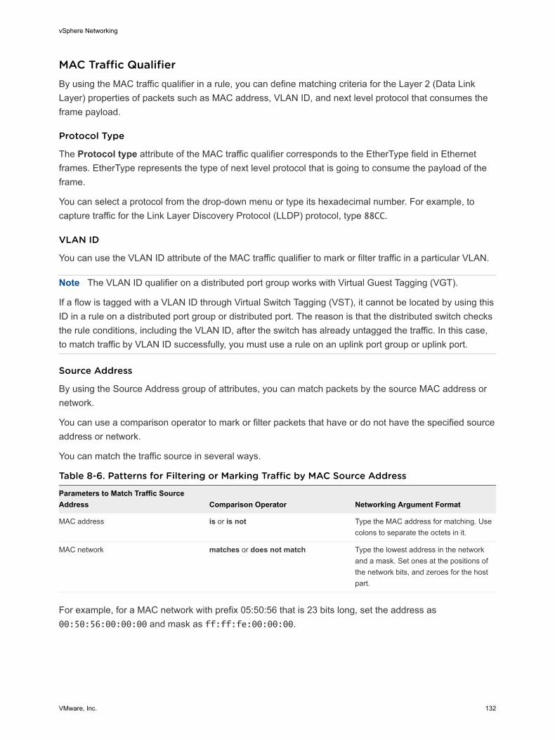
MAC Traffic QualifierBy using the MAC traffic qualifier in a rule, you can define matching criteria for the Layer 2 (Data Link Layer) properties of packets such as MAC address, VLAN ID, and next level protocol that consumes the frame payload.
Protocol Type
The Protocol type attribute of the MAC traffic qualifier corresponds to the EtherType field in Ethernet frames. EtherType represents the type of next level protocol that is going to consume the payload of the frame.
You can select a protocol from the drop-down menu or type its hexadecimal number. For example, to capture traffic for the Link Layer Discovery Protocol (LLDP) protocol, type 88CC.
VLAN ID
You can use the VLAN ID attribute of the MAC traffic qualifier to mark or filter traffic in a particular VLAN.
Note The VLAN ID qualifier on a distributed port group works with Virtual Guest Tagging (VGT).
If a flow is tagged with a VLAN ID through Virtual Switch Tagging (VST), it cannot be located by using this ID in a rule on a distributed port group or distributed port. The reason is that the distributed switch checks the rule conditions, including the VLAN ID, after the switch has already untagged the traffic. In this case, to match traffic by VLAN ID successfully, you must use a rule on an uplink port group or uplink port.
Source Address
By using the Source Address group of attributes, you can match packets by the source MAC address or network.
You can use a comparison operator to mark or filter packets that have or do not have the specified source address or network.
You can match the traffic source in several ways.
Table 8-6. Patterns for Filtering or Marking Traffic by MAC Source Address
Parameters to Match Traffic Source Address Comparison Operator Networking Argument Format
MAC address is or is not Type the MAC address for matching. Use colons to separate the octets in it.
MAC network matches or does not match Type the lowest address in the network and a mask. Set ones at the positions of the network bits, and zeroes for the host part.
For example, for a MAC network with prefix 05:50:56 that is 23 bits long, set the address as 00:50:56:00:00:00 and mask as ff:ff:fe:00:00:00.
vSphere Networking
VMware, Inc. 132
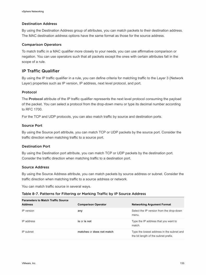
Destination Address
By using the Destination Address group of attributes, you can match packets to their destination address. The MAC destination address options have the same format as those for the source address.
Comparison Operators
To match traffic in a MAC qualifier more closely to your needs, you can use affirmative comparison or negation. You can use operators such that all packets except the ones with certain attributes fall in the scope of a rule.
IP Traffic QualifierBy using the IP traffic qualifier in a rule, you can define criteria for matching traffic to the Layer 3 (Network Layer) properties such as IP version, IP address, next level protocol, and port.
Protocol
The Protocol attribute of the IP traffic qualifier represents the next level protocol consuming the payload of the packet. You can select a protocol from the drop-down menu or type its decimal number according to RFC 1700.
For the TCP and UDP protocols, you can also match traffic by source and destination ports.
Source Port
By using the Source port attribute, you can match TCP or UDP packets by the source port. Consider the traffic direction when matching traffic to a source port.
Destination Port
By using the Destination port attribute, you can match TCP or UDP packets by the destination port. Consider the traffic direction when matching traffic to a destination port.
Source Address
By using the Source Address attribute, you can match packets by source address or subnet. Consider the traffic direction when matching traffic to a source address or network.
You can match traffic source in several ways.
Table 8-7. Patterns for Filtering or Marking Traffic by IP Source Address
Parameters to Match Traffic Source Address Comparison Operator Networking Argument Format
IP version any Select the IP version from the drop-down menu.
IP address is or is not Type the IP address that you want to match.
IP subnet matches or does not match Type the lowest address in the subnet and the bit length of the subnet prefix.
vSphere Networking
VMware, Inc. 133
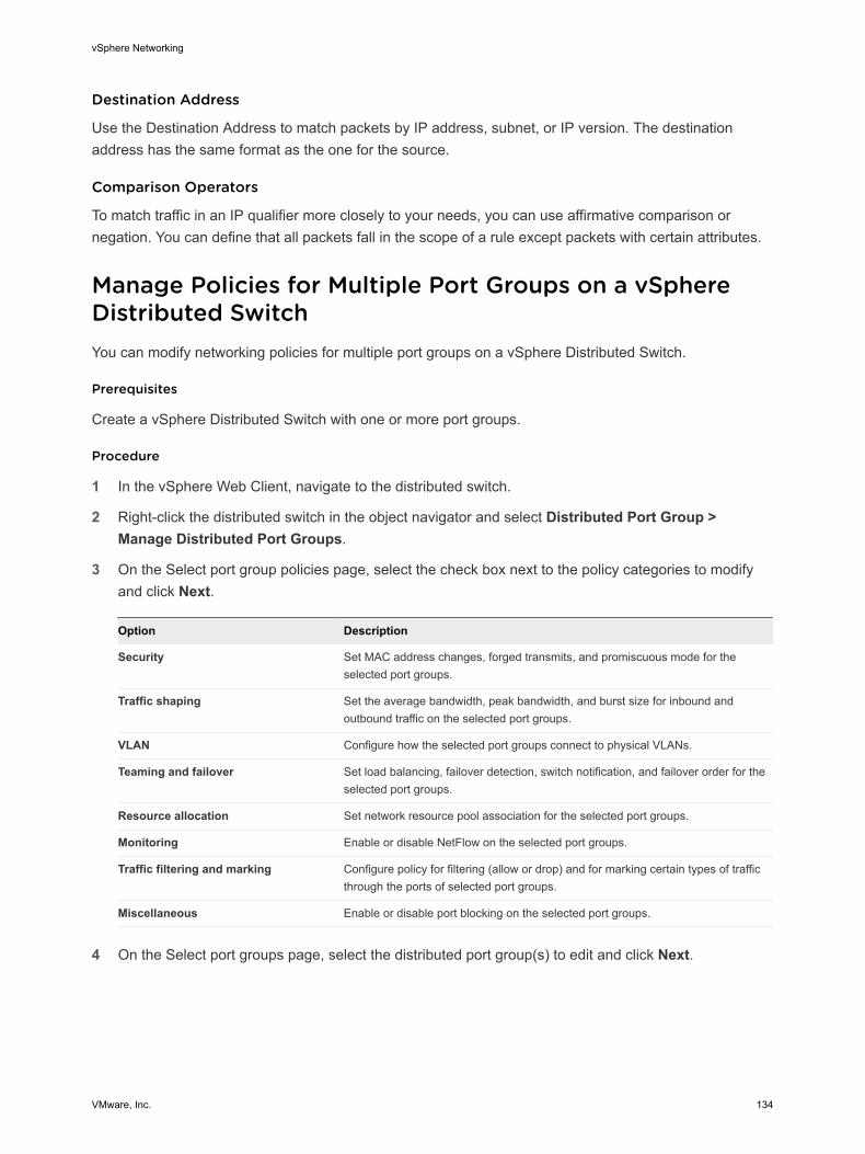
Destination Address
Use the Destination Address to match packets by IP address, subnet, or IP version. The destination address has the same format as the one for the source.
Comparison Operators
To match traffic in an IP qualifier more closely to your needs, you can use affirmative comparison or negation. You can define that all packets fall in the scope of a rule except packets with certain attributes.
Manage Policies for Multiple Port Groups on a vSphere Distributed SwitchYou can modify networking policies for multiple port groups on a vSphere Distributed Switch.
Prerequisites
Create a vSphere Distributed Switch with one or more port groups.
Procedure
1 In the vSphere Web Client, navigate to the distributed switch.
2 Right-click the distributed switch in the object navigator and select Distributed Port Group > Manage Distributed Port Groups.
3 On the Select port group policies page, select the check box next to the policy categories to modify and click Next.
Option Description
Security Set MAC address changes, forged transmits, and promiscuous mode for the selected port groups.
Traffic shaping Set the average bandwidth, peak bandwidth, and burst size for inbound and outbound traffic on the selected port groups.
VLAN Configure how the selected port groups connect to physical VLANs.
Teaming and failover Set load balancing, failover detection, switch notification, and failover order for the selected port groups.
Resource allocation Set network resource pool association for the selected port groups.
Monitoring Enable or disable NetFlow on the selected port groups.
Traffic filtering and marking Configure policy for filtering (allow or drop) and for marking certain types of traffic through the ports of selected port groups.
Miscellaneous Enable or disable port blocking on the selected port groups.
4 On the Select port groups page, select the distributed port group(s) to edit and click Next.
vSphere Networking
VMware, Inc. 134
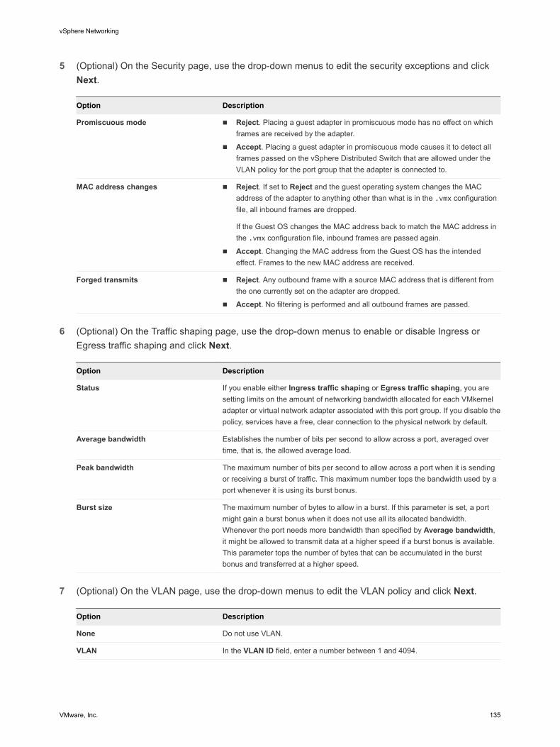
5 (Optional) On the Security page, use the drop-down menus to edit the security exceptions and click Next.
Option Description
Promiscuous mode n Reject. Placing a guest adapter in promiscuous mode has no effect on which frames are received by the adapter.
n Accept. Placing a guest adapter in promiscuous mode causes it to detect all frames passed on the vSphere Distributed Switch that are allowed under the VLAN policy for the port group that the adapter is connected to.
MAC address changes n Reject. If set to Reject and the guest operating system changes the MAC address of the adapter to anything other than what is in the .vmx configuration file, all inbound frames are dropped.
If the Guest OS changes the MAC address back to match the MAC address in the .vmx configuration file, inbound frames are passed again.
n Accept. Changing the MAC address from the Guest OS has the intended effect. Frames to the new MAC address are received.
Forged transmits n Reject. Any outbound frame with a source MAC address that is different from the one currently set on the adapter are dropped.
n Accept. No filtering is performed and all outbound frames are passed.
6 (Optional) On the Traffic shaping page, use the drop-down menus to enable or disable Ingress or Egress traffic shaping and click Next.
Option Description
Status If you enable either Ingress traffic shaping or Egress traffic shaping, you are setting limits on the amount of networking bandwidth allocated for each VMkernel adapter or virtual network adapter associated with this port group. If you disable the policy, services have a free, clear connection to the physical network by default.
Average bandwidth Establishes the number of bits per second to allow across a port, averaged over time, that is, the allowed average load.
Peak bandwidth The maximum number of bits per second to allow across a port when it is sending or receiving a burst of traffic. This maximum number tops the bandwidth used by a port whenever it is using its burst bonus.
Burst size The maximum number of bytes to allow in a burst. If this parameter is set, a port might gain a burst bonus when it does not use all its allocated bandwidth. Whenever the port needs more bandwidth than specified by Average bandwidth, it might be allowed to transmit data at a higher speed if a burst bonus is available. This parameter tops the number of bytes that can be accumulated in the burst bonus and transferred at a higher speed.
7 (Optional) On the VLAN page, use the drop-down menus to edit the VLAN policy and click Next.
Option Description
None Do not use VLAN.
VLAN In the VLAN ID field, enter a number between 1 and 4094.
vSphere Networking
VMware, Inc. 135
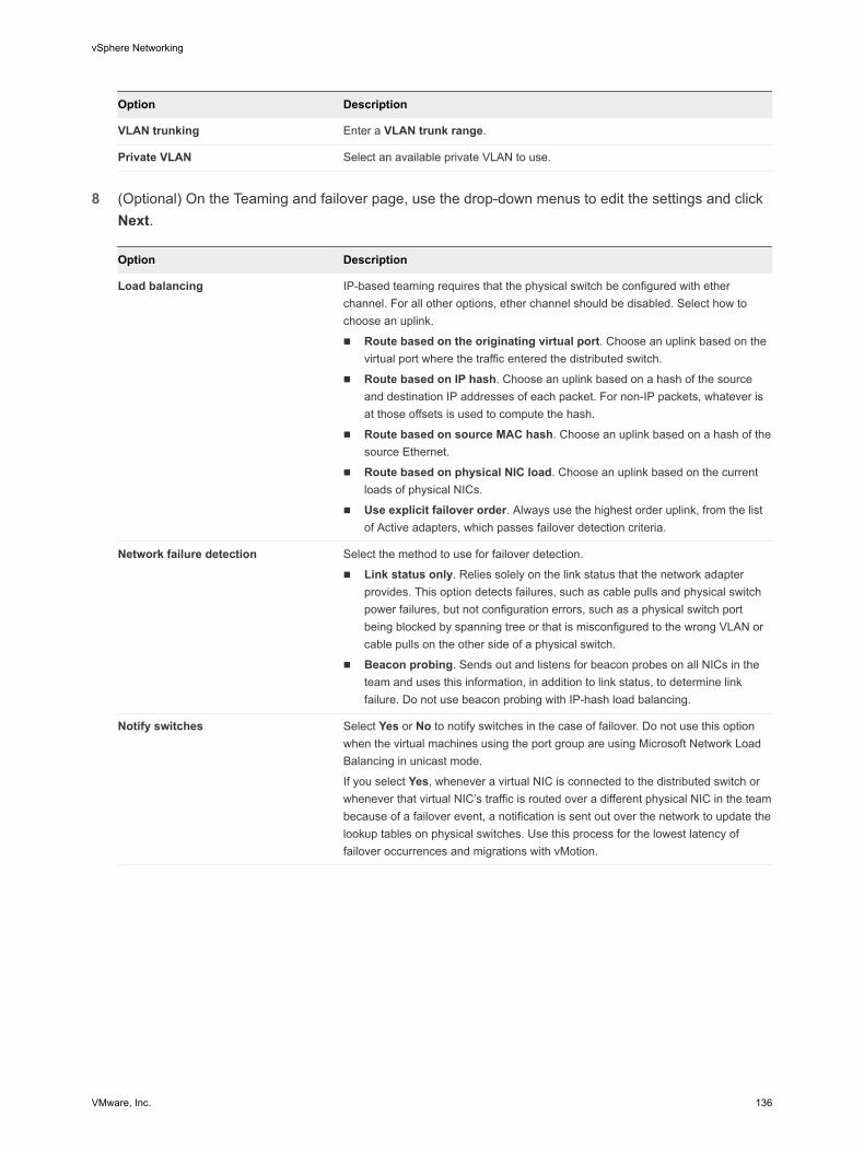
Option Description
VLAN trunking Enter a VLAN trunk range.
Private VLAN Select an available private VLAN to use.
8 (Optional) On the Teaming and failover page, use the drop-down menus to edit the settings and click Next.
Option Description
Load balancing IP-based teaming requires that the physical switch be configured with ether channel. For all other options, ether channel should be disabled. Select how to choose an uplink.
n Route based on the originating virtual port. Choose an uplink based on the virtual port where the traffic entered the distributed switch.
n Route based on IP hash. Choose an uplink based on a hash of the source and destination IP addresses of each packet. For non-IP packets, whatever is at those offsets is used to compute the hash.
n Route based on source MAC hash. Choose an uplink based on a hash of the source Ethernet.
n Route based on physical NIC load. Choose an uplink based on the current loads of physical NICs.
n Use explicit failover order. Always use the highest order uplink, from the list of Active adapters, which passes failover detection criteria.
Network failure detection Select the method to use for failover detection.
n Link status only. Relies solely on the link status that the network adapter provides. This option detects failures, such as cable pulls and physical switch power failures, but not configuration errors, such as a physical switch port being blocked by spanning tree or that is misconfigured to the wrong VLAN or cable pulls on the other side of a physical switch.
n Beacon probing. Sends out and listens for beacon probes on all NICs in the team and uses this information, in addition to link status, to determine link failure. Do not use beacon probing with IP-hash load balancing.
Notify switches Select Yes or No to notify switches in the case of failover. Do not use this option when the virtual machines using the port group are using Microsoft Network Load Balancing in unicast mode.
If you select Yes, whenever a virtual NIC is connected to the distributed switch or whenever that virtual NIC’s traffic is routed over a different physical NIC in the team because of a failover event, a notification is sent out over the network to update the lookup tables on physical switches. Use this process for the lowest latency of failover occurrences and migrations with vMotion.
vSphere Networking
VMware, Inc. 136
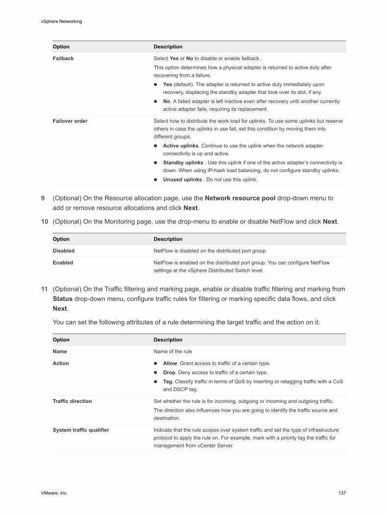
Option Description
Failback Select Yes or No to disable or enable failback.
This option determines how a physical adapter is returned to active duty after recovering from a failure.
n Yes (default). The adapter is returned to active duty immediately upon recovery, displacing the standby adapter that took over its slot, if any.
n No. A failed adapter is left inactive even after recovery until another currently active adapter fails, requiring its replacement.
Failover order Select how to distribute the work load for uplinks. To use some uplinks but reserve others in case the uplinks in use fail, set this condition by moving them into different groups.
n Active uplinks. Continue to use the uplink when the network adapter connectivity is up and active.
n Standby uplinks . Use this uplink if one of the active adapter’s connectivity is down. When using IP-hash load balancing, do not configure standby uplinks.
n Unused uplinks . Do not use this uplink.
9 (Optional) On the Resource allocation page, use the Network resource pool drop-down menu to add or remove resource allocations and click Next.
10 (Optional) On the Monitoring page, use the drop-menu to enable or disable NetFlow and click Next.
Option Description
Disabled NetFlow is disabled on the distributed port group.
Enabled NetFlow is enabled on the distributed port group. You can configure NetFlow settings at the vSphere Distributed Switch level.
11 (Optional) On the Traffic filtering and marking page, enable or disable traffic filtering and marking from
Status drop-down menu, configure traffic rules for filtering or marking specific data flows, and click Next.
You can set the following attributes of a rule determining the target traffic and the action on it:
Option Description
Name Name of the rule
Action n Allow. Grant access to traffic of a certain type.
n Drop. Deny access to traffic of a certain type.
n Tag. Classify traffic in terms of QoS by inserting or retagging traffic with a CoS and DSCP tag.
Traffic direction Set whether the rule is for incoming, outgoing or incoming and outgoing traffic.
The direction also influences how you are going to identify the traffic source and destination.
System traffic qualifier Indicate that the rule scopes over system traffic and set the type of infrastructure protocol to apply the rule on. For example, mark with a priority tag the traffic for management from vCenter Server.
vSphere Networking
VMware, Inc. 137
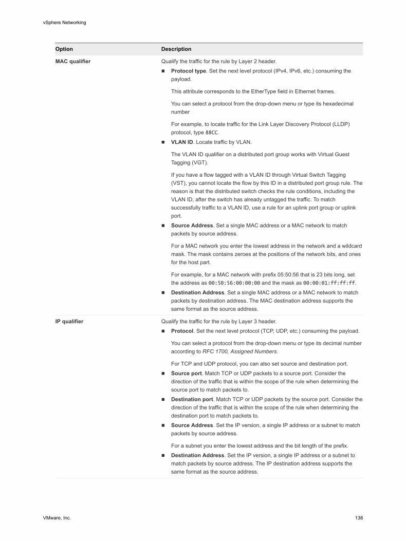
Option Description
MAC qualifier Qualify the traffic for the rule by Layer 2 header.
n Protocol type. Set the next level protocol (IPv4, IPv6, etc.) consuming the payload.
This attribute corresponds to the EtherType field in Ethernet frames.
You can select a protocol from the drop-down menu or type its hexadecimal number
For example, to locate traffic for the Link Layer Discovery Protocol (LLDP) protocol, type 88CC.
n VLAN ID. Locate traffic by VLAN.
The VLAN ID qualifier on a distributed port group works with Virtual Guest Tagging (VGT).
If you have a flow tagged with a VLAN ID through Virtual Switch Tagging (VST), you cannot locate the flow by this ID in a distributed port group rule. The reason is that the distributed switch checks the rule conditions, including the VLAN ID, after the switch has already untagged the traffic. To match successfully traffic to a VLAN ID, use a rule for an uplink port group or uplink port.
n Source Address. Set a single MAC address or a MAC network to match packets by source address.
For a MAC network you enter the lowest address in the network and a wildcard mask. The mask contains zeroes at the positions of the network bits, and ones for the host part.
For example, for a MAC network with prefix 05:50:56 that is 23 bits long, set the address as 00:50:56:00:00:00 and the mask as 00:00:01:ff:ff:ff.
n Destination Address. Set a single MAC address or a MAC network to match packets by destination address. The MAC destination address supports the same format as the source address.
IP qualifier Qualify the traffic for the rule by Layer 3 header.
n Protocol. Set the next level protocol (TCP, UDP, etc.) consuming the payload.
You can select a protocol from the drop-down menu or type its decimal number according to RFC 1700, Assigned Numbers.
For TCP and UDP protocol, you can also set source and destination port.
n Source port. Match TCP or UDP packets to a source port. Consider the direction of the traffic that is within the scope of the rule when determining the source port to match packets to.
n Destination port. Match TCP or UDP packets by the source port. Consider the direction of the traffic that is within the scope of the rule when determining the destination port to match packets to.
n Source Address. Set the IP version, a single IP address or a subnet to match packets by source address.
For a subnet you enter the lowest address and the bit length of the prefix.
n Destination Address. Set the IP version, a single IP address or a subnet to match packets by source address. The IP destination address supports the same format as the source address.
vSphere Networking
VMware, Inc. 138
12 (Optional) On the Miscellaneous page, select Yes or No from the drop-down menu and click Next.
SelectYes to shut down all ports in the port group. This shutdown might disrupt the normal network operations of the hosts or virtual machines using the ports.
13 Review your settings on the Ready to complete page and click Finish.
Use the Back button to change any settings.
Port Blocking PoliciesPort blocking policies allow you to selectively block ports from sending or receiving data.
Edit the Port Blocking Policy for a Distributed Port GroupYou can block all ports in a distributed port group.
Blocking the ports of a distributed port group might disrupt the normal network operations of the hosts or virtual machines using the ports.
Procedure
1 In the vSphere Web Client, navigate to the distributed switch.
2 Right-click the distributed switch in the object navigator and select Distributed Port Group > Manage Distributed Port Groups.
3 Select the Miscellaneous check box and click Next.
4 Select one or more distributed port group to configure and click Next.
5 From the Block all ports drop-down menu, enable or disable port blocking, and click Next.
6 Review your settings and click Finish.
Edit the Blocking Policy for a Distributed Port or Uplink PortYou can block an individual distributed port or uplink port.
Blocking the flow through a port might disrupt the normal network operations on the host or virtual machine using the port.
Prerequisites
Enable the port-level overrides. See Configure Overriding Networking Policies on Port Level
Procedure
1 Navigate to a distributed switch and then navigate to a distributed port or an uplink port.
n To navigate to the distributed ports of the switch, click Networks > Distributed Port Groups, double-click a distributed port group from the list, and click the Ports tab.
n To navigate to the uplink ports of an uplink port group, click Networks > Uplink Port Groups, double-click an uplink port group from the list, and click the Ports tab.
vSphere Networking
VMware, Inc. 139

2 Select a port from the list.
3 Click Edit distributed port settings.
4 In the Miscellaneous section, select the Override check box, and from the drop-down menu enable or disable port blocking.
5 Click OK.
vSphere Networking
VMware, Inc. 140
Isolating Network Traffic by Using VLANs 9VLANs let you segment a network into multiple logical broadcast domains at Layer 2 of the network protocol stack.
This chapter includes the following topics:
n VLAN Configuration
n Private VLANs
VLAN ConfigurationVirtual LANs (VLANs) enable a single physical LAN segment to be further isolated so that groups of ports are isolated from one another as if they were on physically different segments.
Benefits of Using VLANs in vSphereThe VLAN configuration in a vSphere environment provides certain benefits.
n Integrates ESXi hosts into a pre-existing VLAN topology.
n Isolates and secures network traffic.
n Reduces congestion of network traffic.
Watch the video about the benefits and main principles in introducing VLANs in a vSphere environment.
Using VLANs in a vSphere Environment (http://link.brightcove.com/services/player/bcpid2296383276001?bctid=ref:video_using_vlans_in_vsphere)
VLAN Tagging ModesvSphere supports three modes of VLAN tagging in ESXi: External Switch Tagging (EST), Virtual Switch Tagging (VST), and Virtual Guest Tagging (VGT).
VMware, Inc. 141
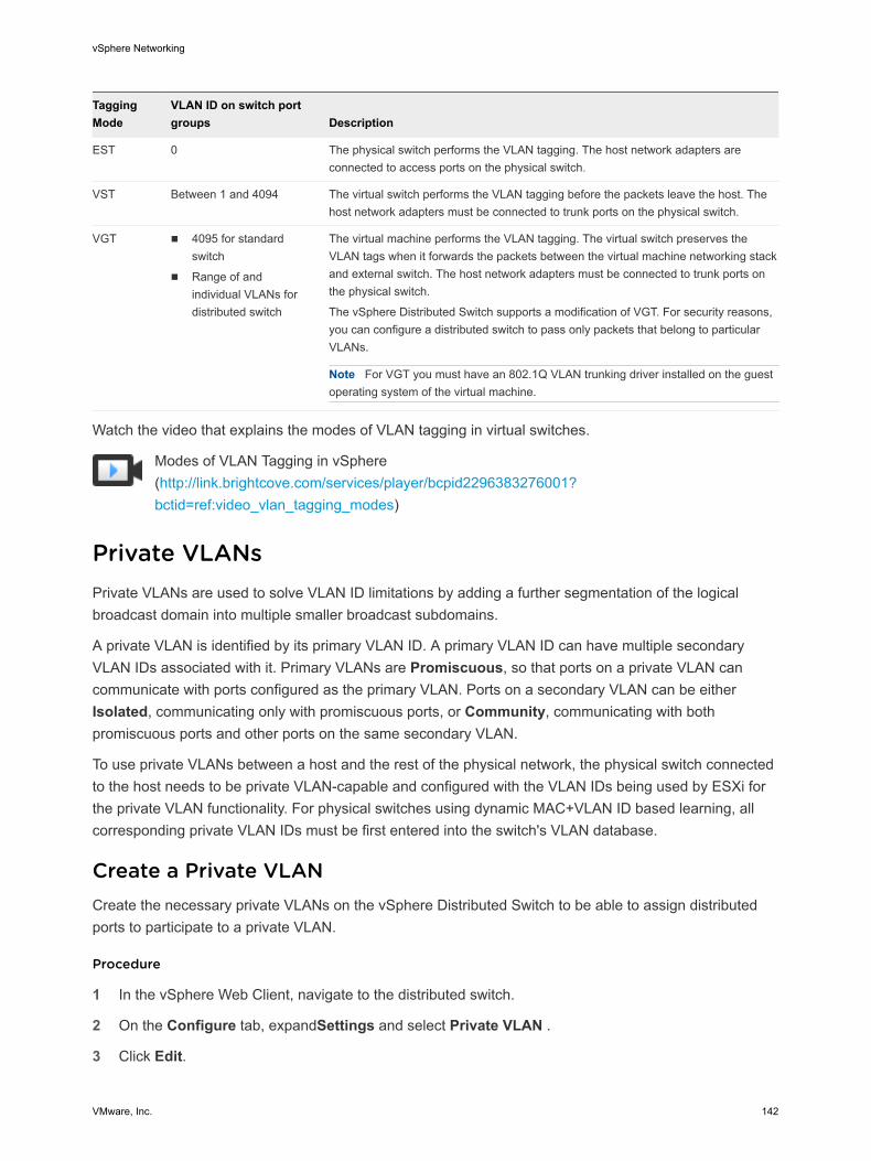
Tagging Mode
VLAN ID on switch port groups Description
EST 0 The physical switch performs the VLAN tagging. The host network adapters are connected to access ports on the physical switch.
VST Between 1 and 4094 The virtual switch performs the VLAN tagging before the packets leave the host. The host network adapters must be connected to trunk ports on the physical switch.
VGT n 4095 for standard switch
n Range of and individual VLANs for distributed switch
The virtual machine performs the VLAN tagging. The virtual switch preserves the VLAN tags when it forwards the packets between the virtual machine networking stack and external switch. The host network adapters must be connected to trunk ports on the physical switch.
The vSphere Distributed Switch supports a modification of VGT. For security reasons, you can configure a distributed switch to pass only packets that belong to particular VLANs.
Note For VGT you must have an 802.1Q VLAN trunking driver installed on the guest operating system of the virtual machine.
Watch the video that explains the modes of VLAN tagging in virtual switches.
Modes of VLAN Tagging in vSphere (http://link.brightcove.com/services/player/bcpid2296383276001?bctid=ref:video_vlan_tagging_modes)
Private VLANsPrivate VLANs are used to solve VLAN ID limitations by adding a further segmentation of the logical broadcast domain into multiple smaller broadcast subdomains.
A private VLAN is identified by its primary VLAN ID. A primary VLAN ID can have multiple secondary VLAN IDs associated with it. Primary VLANs are Promiscuous, so that ports on a private VLAN can communicate with ports configured as the primary VLAN. Ports on a secondary VLAN can be either Isolated, communicating only with promiscuous ports, or Community, communicating with both promiscuous ports and other ports on the same secondary VLAN.
To use private VLANs between a host and the rest of the physical network, the physical switch connected to the host needs to be private VLAN-capable and configured with the VLAN IDs being used by ESXi for the private VLAN functionality. For physical switches using dynamic MAC+VLAN ID based learning, all corresponding private VLAN IDs must be first entered into the switch's VLAN database.
Create a Private VLANCreate the necessary private VLANs on the vSphere Distributed Switch to be able to assign distributed ports to participate to a private VLAN.
Procedure
1 In the vSphere Web Client, navigate to the distributed switch.
2 On the Configure tab, expandSettings and select Private VLAN .
3 Click Edit.
vSphere Networking
VMware, Inc. 142
4 To add a primary VLAN, under Primary VLAN ID click Add and enter the ID of a primary VLAN.
5 Click the plus sign (+) in front of the primary VLAN ID to add it to the list.
The primary private VLAN also appears under Secondary Private VLAN ID.
6 To add a secondary VLAN, in the right pane click Add and enter the ID of the VLAN.
7 Click the plus sign (+) in front of the secondary VLAN ID to add it to the list.
8 From the drop-down menu in the Secondary VLAN type column, select either Isolated or Community.
9 Click OK.
What to do next
Configure a distributed port group or port to associate traffic with the private VLAN. See Configure VLAN Tagging on a Distributed Port Group or Distributed Port.
Remove a Primary Private VLANRemove unused primary VLANs from the configuration of a vSphere Distributed Switch.
When you remove a primary private VLAN, you also remove the associated secondary private VLANs.
Prerequisites
Verify that no port groups are configured to use the primary VLAN and its associated secondary VLANs.
Procedure
1 In the vSphere Web Client, navigate to the distributed switch.
2 On the Configure tab, expand Settings and select Private VLAN.
3 Click Edit.
4 Select the primary private VLAN to remove.
5 Click Remove under the Primary VLAN ID list.
6 Click OK to confirm that you want to remove the primary VLAN.
7 Click OK.
Remove a Secondary Private VLANRemove unused secondary private VLANs from the configuration of a vSphere Distributed Switch.
Prerequisites
Verify that no port groups are configured to use the secondary VLAN.
Procedure
1 In the vSphere Web Client, navigate to the distributed switch.
vSphere Networking
VMware, Inc. 143

2 On the Configure tab, expand Settings and select Private VLAN.
3 Click Edit.
4 Select a primary private VLAN.
The secondary private VLANs associated with it appear on the right.
5 Select the secondary private VLAN to remove.
6 Under the secondary VLAN ID list, click Remove and click OK.
vSphere Networking
VMware, Inc. 144
Managing Network Resources 10vSphere provides several different methods to help you manage your network resources.
This chapter includes the following topics:
n DirectPath I/O
n Single Root I/O Virtualization (SR-IOV)
n Remote Direct Memory Access for Virtual Machines
n Jumbo Frames
n TCP Segmentation Offload
n Large Receive Offload
n NetQueue and Networking Performance
DirectPath I/ODirectPath I/O allows virtual machine access to physical PCI functions on platforms with an I/O Memory Management Unit.
The following features are unavailable for virtual machines configured with DirectPath:
n Hot adding and removing of virtual devices
n Suspend and resume
n Record and replay
n Fault tolerance
n High availability
n DRS (limited availability. The virtual machine can be part of a cluster, but cannot migrate across hosts)
VMware, Inc. 145

n Snapshots
n Enable Passthrough for a Network Device on a Host
Passthrough devices provide the means to use resources efficiently and improve performance of your environment. You can enable DirectPath I/O passthrough for a network device on a host.
n Configure a PCI Device on a Virtual Machine
Passthrough devices provide the means to more efficiently use resources and improve performance in your environment. You can configure a passthrough PCI device on a virtual machine in the vSphere Web Client.
Enable Passthrough for a Network Device on a HostPassthrough devices provide the means to use resources efficiently and improve performance of your environment. You can enable DirectPath I/O passthrough for a network device on a host.
Caution If your ESXi host is configured to boot from a USB device or an SD card attached to a USB channel, make sure that you do not enable DirectPath I/O passthrough for the USB controller. Passing through a USB controller on an ESXi host that boots from a USB device or SD card might put the host in a state where its configuration cannot be persisted.
Procedure
1 Browse to a host in the vSphere Web Client navigator.
2 On the Configure tab, expand Hardware and click PCI Devices.
3 To enable DirectPath I/O passthrough for a PCI network device on the host, click Edit.
A list of available passthrough devices appears.
Icon Description
green icon A device is active and can be enabled.
orange icon The state of the device has changed, and you must reboot the host before you can use the device.
4 Select the network device to be used for passthrough and click OK.
The selected PCI device appears in the table. Device information is displayed at the bottom of the screen.
5 Reboot the host to make the PCI network device available for use.
Configure a PCI Device on a Virtual MachinePassthrough devices provide the means to more efficiently use resources and improve performance in your environment. You can configure a passthrough PCI device on a virtual machine in the vSphere Web Client.
When using passthrough devices with a Linux kernel version 2.6.20 or earlier, avoid MSI and MSI-X modes because these modes have significant performance impact.
vSphere Networking
VMware, Inc. 146
Prerequisites
Verify that a passthrough networking device is configured on the host of the virtual machine. See Enable Passthrough for a Network Device on a Host.
Procedure
1 Locate the virtual machine in the vSphere Web Client.
a Select a data center, folder, cluster, resource pool, or host and click the VMs tab.
b Click Virtual Machines and double-click the virtual machine from the list.
2 Power off the virtual machine.
3 On the Configure tab of the virtual machine, expand Settings and select VM Hardware.
4 Click Edit and select the Virtual Hardware tab in the dialog box displaying the settings.
5 Expand the Memory section, and set the Limit to Unlimited.
6 From the New device drop-down menu select PCI Device and click Add.
7 From the New PCI device drop-down menu select the passthrough device to use, and click OK.
8 Power on the virtual machine.
Results
Adding a DirectPath I/O device to a virtual machine sets memory reservation to the memory size of the virtual machine.
Single Root I/O Virtualization (SR-IOV)vSphere supports Single Root I/O Virtualization (SR-IOV). You can use SR-IOV for networking of virtual machines that are latency sensitive or require more CPU resources.
Overview of SR-IOVSR-IOV is a specification that allows a single Peripheral Component Interconnect Express (PCIe) physical device under a single root port to appear as multiple separate physical devices to the hypervisor or the guest operating system.
SR-IOV uses physical functions (PFs) and virtual functions (VFs) to manage global functions for the SR-IOV devices. PFs are full PCIe functions that are capable of configuring and managing the SR-IOV functionality. It is possible to configure or control PCIe devices using PFs, and the PF has full ability to move data in and out of the device. VFs are lightweight PCIe functions that support data flowing but have a restricted set of configuration resources.
The number of virtual functions provided to the hypervisor or the guest operating system depends on the device. SR-IOV enabled PCIe devices require appropriate BIOS and hardware support, as well as SR-IOV support in the guest operating system driver or hypervisor instance. See SR-IOV Support.
vSphere Networking
VMware, Inc. 147
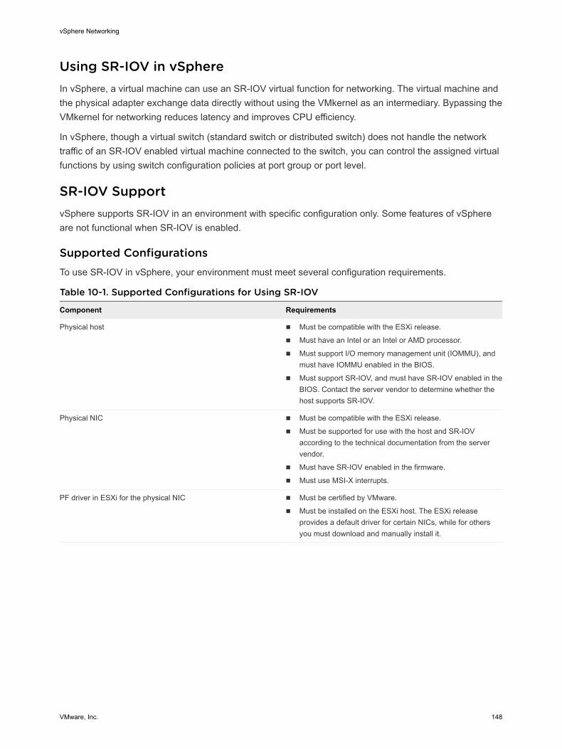
Using SR-IOV in vSphereIn vSphere, a virtual machine can use an SR-IOV virtual function for networking. The virtual machine and the physical adapter exchange data directly without using the VMkernel as an intermediary. Bypassing the VMkernel for networking reduces latency and improves CPU efficiency.
In vSphere, though a virtual switch (standard switch or distributed switch) does not handle the network traffic of an SR-IOV enabled virtual machine connected to the switch, you can control the assigned virtual functions by using switch configuration policies at port group or port level.
SR-IOV SupportvSphere supports SR-IOV in an environment with specific configuration only. Some features of vSphere are not functional when SR-IOV is enabled.
Supported ConfigurationsTo use SR-IOV in vSphere, your environment must meet several configuration requirements.
Table 10-1. Supported Configurations for Using SR-IOV
Component Requirements
Physical host n Must be compatible with the ESXi release.
n Must have an Intel or an Intel or AMD processor.
n Must support I/O memory management unit (IOMMU), and must have IOMMU enabled in the BIOS.
n Must support SR-IOV, and must have SR-IOV enabled in the BIOS. Contact the server vendor to determine whether the host supports SR-IOV.
Physical NIC n Must be compatible with the ESXi release.
n Must be supported for use with the host and SR-IOV according to the technical documentation from the server vendor.
n Must have SR-IOV enabled in the firmware.
n Must use MSI-X interrupts.
PF driver in ESXi for the physical NIC n Must be certified by VMware.
n Must be installed on the ESXi host. The ESXi release provides a default driver for certain NICs, while for others you must download and manually install it.
vSphere Networking
VMware, Inc. 148
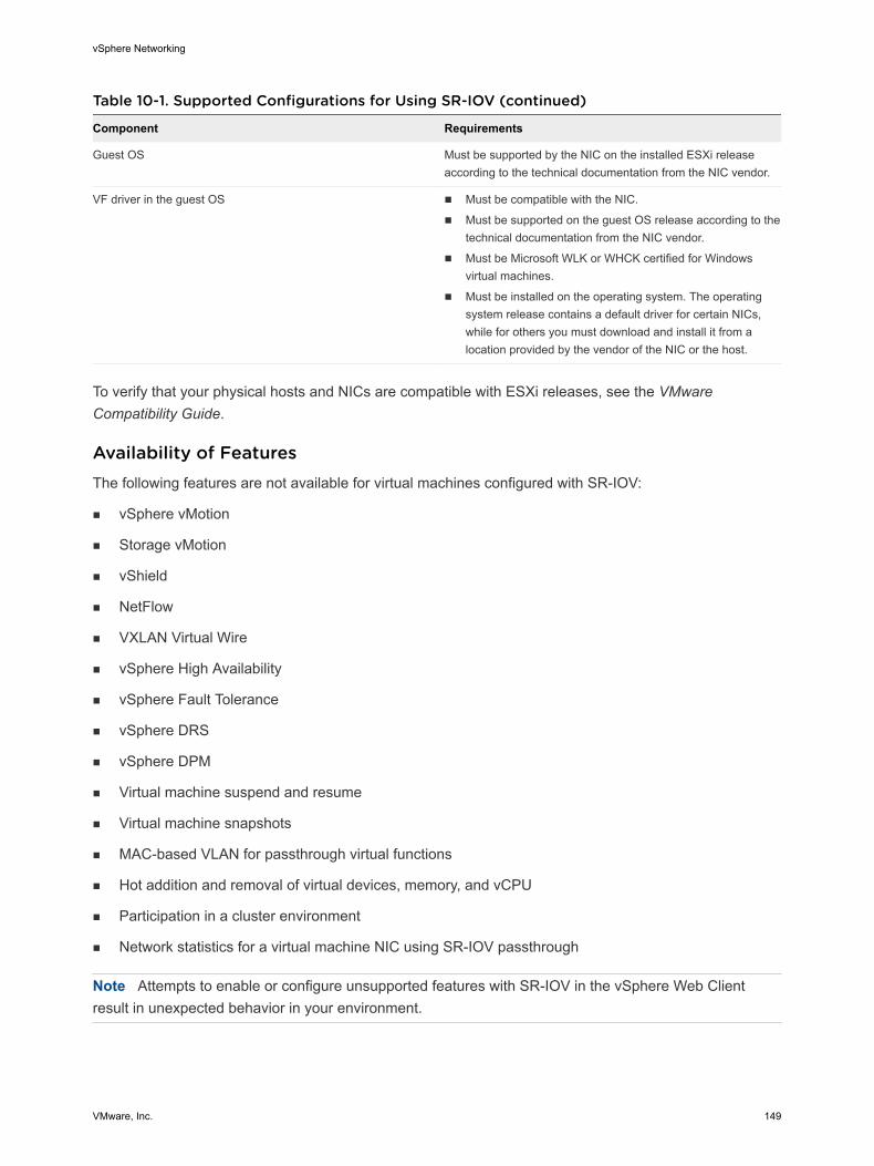
Table 10-1. Supported Configurations for Using SR-IOV (continued)
Component Requirements
Guest OS Must be supported by the NIC on the installed ESXi release according to the technical documentation from the NIC vendor.
VF driver in the guest OS n Must be compatible with the NIC.
n Must be supported on the guest OS release according to the technical documentation from the NIC vendor.
n Must be Microsoft WLK or WHCK certified for Windows virtual machines.
n Must be installed on the operating system. The operating system release contains a default driver for certain NICs, while for others you must download and install it from a location provided by the vendor of the NIC or the host.
To verify that your physical hosts and NICs are compatible with ESXi releases, see the VMware Compatibility Guide.
Availability of FeaturesThe following features are not available for virtual machines configured with SR-IOV:
n vSphere vMotion
n Storage vMotion
n vShield
n NetFlow
n VXLAN Virtual Wire
n vSphere High Availability
n vSphere Fault Tolerance
n vSphere DRS
n vSphere DPM
n Virtual machine suspend and resume
n Virtual machine snapshots
n MAC-based VLAN for passthrough virtual functions
n Hot addition and removal of virtual devices, memory, and vCPU
n Participation in a cluster environment
n Network statistics for a virtual machine NIC using SR-IOV passthrough
Note Attempts to enable or configure unsupported features with SR-IOV in the vSphere Web Client result in unexpected behavior in your environment.
vSphere Networking
VMware, Inc. 149
Supported NICsAll NICs must have drivers and firmware that support SR-IOV. Some NICs might require SR-IOV to be enabled on the firmware. The following NICs are supported for virtual machines configured with SR-IOV:
n Products based on the Intel 82599ES 10 Gigabit Ethernet Controller Family (Niantic)
n Products based on the Intel Ethernet Controller X540 Family (Twinville)
n Products based on the Intel Ethernet Controller X710 Family (Fortville)
n Products based on the Intel Ethernet Controller XL170 Family (Fortville)
n Emulex OneConnect (BE3)
SR-IOV Component Architecture and InteractionvSphere SR-IOV support relies on the interaction between the virtual functions (VFs) and the physical function (PF) of the NIC port for better performance, and interaction between the driver of the PF and the host switch for traffic control.
In a host that runs virtual machine traffic on top of SR-IOV physical adapters, virtual machine adapters directly contact the virtual functions to communicate data. However, the ability to configure networks is based on the active policies for the port holding the virtual machines.
On an ESXi host without SR-IOV, the virtual switch sends external network traffic through its ports on the host from or to the physical adapter for the relevant port group. The virtual switch also applies the networking policies on managed packets.
vSphere Networking
VMware, Inc. 150
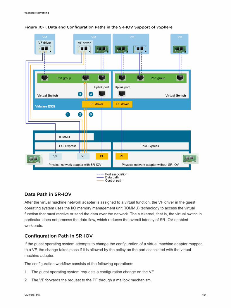
Figure 10-1. Data and Configuration Paths in the SR-IOV Support of vSphere
IOMMU
PCI Express
Physical network adapter with SR-IOV
PCI Express
Physical network adapter without SR-IOV
Port group
Uplink port
Port associationData pathControl path
Port group
Uplink port
VMware ESXi
Virtual Switch Virtual Switch
VMVM
1
3 4
2 5
VM
VF driver
VM
VF driver
PF
PF driver PF driver
VFVF PF
Data Path in SR-IOVAfter the virtual machine network adapter is assigned to a virtual function, the VF driver in the guest operating system uses the I/O memory management unit (IOMMU) technology to access the virtual function that must receive or send the data over the network. The VMkernel, that is, the virtual switch in particular, does not process the data flow, which reduces the overall latency of SR-IOV enabled workloads.
Configuration Path in SR-IOVIf the guest operating system attempts to change the configuration of a virtual machine adapter mapped to a VF, the change takes place if it is allowed by the policy on the port associated with the virtual machine adapter.
The configuration workflow consists of the following operations:
1 The guest operating system requests a configuration change on the VF.
2 The VF forwards the request to the PF through a mailbox mechanism.
vSphere Networking
VMware, Inc. 151
3 The PF driver checks the configuration request with the virtual switch (standard switch or host proxy switch of a distributed switch).
4 The virtual switch verifies the configuration request against the policy on the port with which the VF enabled virtual machine adapter is associated.
5 The PF driver configures the VF if the new settings are in compliance with the port policy of the virtual machine adapter.
For example, if the VF driver tries to modify the MAC address, the address remains the same if MAC address change is not allowed in the security policy for the port group or port. The guest operating system might show that the change is successful but a log message indicates that the operation has failed. As a result, the guest operating system and the virtual device save different MAC addresses. The network interface in the guest operating system might not be able to acquire an IP address and communicate. In this case, you have to reset the interface in the guest operating system to get the latest MAC address from the virtual device and acquire an IP address.
vSphere and Virtual Function InteractionVirtual functions (VFs) are lightweight PCIe functions that contain all the resources necessary for data exchange but have a minimized set of configuration resources. Interaction between vSphere and VFs is limited.
n The physical NIC must use MSI-X interrupts.
n VFs do not implement rate control in vSphere. Every VF can potentially use the entire bandwidth of a physical link.
n When a VF device is configured as a passthrough device on a virtual machine, the standby and hibernate functions for the virtual machine are not supported.
n The maximum number of VFs that you can create and the maximum number of VFs that you can use for passthrough are different. The maximum number of VFs that you can instantiate depends on the NIC capability and on the hardware configuration of the host. However, due to the limited number of interrupt vectors available for passthrough devices, only a limited number of all instantiated VFs can be used on an ESXi host.
The total number of interrupt vectors on each ESXi host can scale up to 4096 in the case of 32 CPUs. When the host boots, devices on the host such as storage controllers, physical network adapters, and USB controllers consume a subset of the 4096 vectors. If these devices require more than 1024 vectors, the maximum number of potentially supported VFs is reduced.
n The number of VFs that is supported on an Intel NIC might be different from the number that is supported on an Emulex NIC. See the technical documentation from the NIC vendor.
n If you have Intel and Emulex NICs present with SR-IOV enabled, the number of VFs available for the Intel NICs depends on how many VFs are configured for the Emulex NIC, and the reverse. You can use the following formula to estimate the maximum number of VFs for use if all 3072 interrupt vectors are available for passthrough:
3X + 2Y < 3072
vSphere Networking
VMware, Inc. 152
where X is the number of Intel VFs, and Y is the number of Emulex VFs.
This number might be smaller if other types of devices on the host use more than 1024 interrupt vectors from the total of 4096 vectors on the host.
n vSphere SR-IOV supports up to 1024 VFs on supported Intel and Emulex NICs.
n vSphere SR-IOV supports up to 64 VFs on a supported Intel or Emulex NIC.
n If a supported Intel NIC loses connection, all VFs from the physical NIC stop communication completely, including that between VFs.
n If a supported Emulex NIC loses connection, all VFs stop communication with the external environment, but communication between VFs still works
n VF drivers offer many different features, such as IPv6 support, TSO, and LRO checksum. See the technical documentation of the NIC vendor for more details.
DirectPath I/O vs SR-IOVSR-IOV offers performance benefits and tradeoffs similar to those of DirectPath I/O. DirectPath I/O and SR-IOV have similar functionality but you use them to accomplish different things.
SR-IOV is beneficial in workloads with very high packet rates or very low latency requirements. Like DirectPath I/O, SR-IOV is not compatible with certain core virtualization features, such as vMotion. SR-IOV does, however, allow for a single physical device to be shared amongst multiple guests.
With DirectPath I/O you can map only one physical function to one virtual machine. SR-IOV lets you share a single physical device, allowing multiple virtual machines to connect directly to the physical function.
Configure a Virtual Machine to Use SR-IOVTo use the capabilities of SR-IOV, you must enable the SR-IOV virtual functions on the host and connect a virtual machine to the functions.
Prerequisites
Verify that the configuration of your environment supports SR-IOV. See SR-IOV Support.
Procedure
1 Enable SR-IOV on a Host Physical Adapter
Before you can connect virtual machines to virtual functions, use the vSphere Web Client to enable SR-IOV and set the number of virtual functions on your host.
2 Assign a Virtual Function as SR-IOV Passthrough Adapter to a Virtual Machine
To ensure that a virtual machine and a physical NIC can exchange data, you must associate the virtual machine with one or more virtual functions as SR-IOV passthrough network adapters.
vSphere Networking
VMware, Inc. 153
Results
The traffic passes from an SR-IOV passthrough adapter to the physical adapter in compliance with the active policy on the associated port on the standard or distributed switch.
To examine which virtual function is assigned to an SR-IOV passthrough network adapter, on the Summary tab for the virtual machine expand the VM Hardware panel and check the properties of the adapter.
The topology diagram of the switch marks virtual machine adapters that use virtual functions with the icon.
What to do next
Set up the traffic passing through the virtual functions attached to the virtual machine by using the networking policies on the switch, port group, and port. See Networking Options for the Traffic Related to an SR-IOV Enabled Virtual Machine.
Enable SR-IOV on a Host Physical AdapterBefore you can connect virtual machines to virtual functions, use the vSphere Web Client to enable SR-IOV and set the number of virtual functions on your host.
Procedure
1 In the vSphere Web Client, navigate to the host.
2 On the Configure tab, expand Networking and select Physical adapters.
You can look at the SR-IOV property to see whether a physical adapter supports SR-IOV.
3 Select the physical adapter and click Edit adapter settings.
4 Under SR-IOV, select Enabled from the Status drop-down menu.
5 In the Number of virtual functions text box, type the number of virtual functions that you want to configure for the adapter.
A value of 0 means SR-IOV is not enabled for that physical function.
6 Click OK.
7 Restart the host.
Results
The virtual functions become active on the NIC port represented by the physical adapter entry. They appear in the PCI Devices list in the Settings tab for the host.
You can use the esxcli network sriovnic vCLI commands to examine the configuration of virtual functions on the host.
What to do next
Associate a virtual machine with a virtual function through an SR-IOV passthrough network adapter.
vSphere Networking
VMware, Inc. 154
Assign a Virtual Function as SR-IOV Passthrough Adapter to a Virtual MachineTo ensure that a virtual machine and a physical NIC can exchange data, you must associate the virtual machine with one or more virtual functions as SR-IOV passthrough network adapters.
Prerequisites
n Verify that the virtual functions exist on the host.
n Verify that the passthrough networking devices for the virtual functions are active in the PCI Devices list on the Settings tab for the host.
n Verify that the virtual machine compatibility is ESXi 5.5 and later.
n Verify that Red Hat Enterprise Linux 6 and later or Windows has been selected as the guest operating system when the virtual machine was created.
Procedure
1 Locate the virtual machine in the vSphere Web Client.
a Select a data center, folder, cluster, resource pool, or host and click the VMs tab.
b Click Virtual Machines and double-click the virtual machine from the list.
2 Power off the virtual machine.
3 On the Configure tab of the virtual machine, expand Settings and select VM Hardware.
4 Click Edit and select the Virtual Hardware tab in the dialog box displaying the settings.
5 From the New device drop-down menu, select Network and click Add.
6 Expand the New Network section and connect the virtual machine to a port group.
The virtual NIC does not use this port group for data traffic. The port group is used to extract the networking properties, for example VLAN tagging, to apply on the data traffic.
7 From the Adapter type drop-down menu, select SR-IOV passthrough.
8 From the Physical function drop-down menu, select the physical adapter to back the passthrough virtual machine adapter.
9 To allow changes in the MTU of packets from the guest operating system, use the Guest OS MTU Change drop-down menu.
10 Expand the Memory section, select Reserve all guest memory (All locked) and click OK.
I/O memory management unit (IOMMU) must reach all virtual machine memory so that the passthrough device can access the memory by using direct memory access (DMA).
11 Power on the virtual machine.
vSphere Networking
VMware, Inc. 155
Results
When you power on the virtual machine, the ESXi host selects a free virtual function from the physical adapter and maps it to the SR-IOV passthrough adapter. The host validates all properties of the virtual machine adapter and the underlying virtual function against the settings of the port group to which the virtual machine belongs.
Networking Options for the Traffic Related to an SR-IOV Enabled Virtual MachineIn vSphere you can configure certain networking features on a virtual machine adapter that is associated virtual function (VF). Use settings for the switch, for the port group, or for a port depending on the type of the virtual switch (standard or distributed) that handles the traffic.
Table 10-2. Networking Options for a Virtual Machine Adapter That Uses a VF
Networking Option Description
MTU size Change the size of the MTU, for example, to enable jumbo frames.
Security policy for VF traffic n If the guest operating system changes the initially set MAC address of a virtual machine network adapter that uses a VF, accept or drop incoming frames for the new address by setting the MAC address changes option.
n Enable global promiscuous mode for virtual machine network adapters, including adapters that use VFs.
VLAN tagging mode Configure VLAN tagging in the standard or distributed switch, that is, enable VLAN Switch Tagging (VST) mode, or let the tagged traffic reach the virtual machines that are associated with VFs, that is, enable Virtual Guest Tagging (VGT).
Using an SR-IOV Physical Adapter to Handle Virtual Machine TrafficIn vSphere both the physical function (PF) and virtual functions (VFs) of an SR-IOV capable physical adapter can be configured to handle virtual machine traffic.
The PF of an SR-IOV physical adapter controls the VFs that virtual machines use, and can carry the traffic flowing through the standard or distributed switch that handles the networking of these SR-IOV enabled virtual machines.
The SR-IOV physical adapter works in different modes depending on whether it backs the traffic of the switch.
Mixed ModeThe physical adapter provides virtual functions to virtual machines attached to the switch and directly handles traffic from non SR-IOV virtual machines on the switch.
vSphere Networking
VMware, Inc. 156
You can check whether an SR-IOV physical adapter is in mixed mode in the topology diagram of the
switch. An SR-IOV physical adapter in mixed mode appears with the icon in the list of physical adapters for a standard switch or in the list of uplink group adapters for a distributed switch.
SR-IOV Only ModeThe physical adapter provides virtual functions to virtual machines connected to a virtual switch, but does not back traffic from non SR-IOV virtual machines on the switch.
To verify whether the physical adapter is in SR-IOV only mode, examine the topology diagram of the switch. In this mode, the physical adapter is in a separate list called External SR-IOV Adapters and
appears with the icon.
Non SR-IOV ModeThe physical adapter is not used for traffic related to VF aware virtual machines. It handles traffic from non SR-IOV virtual machines only.
Enabling SR-IOV by Using Host Profiles or an ESXCLI CommandYou can configure the virtual functions on an ESXi host by using an ESXCLI command, or by using a host profile to set up multiple hosts simultaneously or to set up stateless hosts.
Enable SR-IOV in a Host ProfileFor multiple hosts or a stateless host, you can configure the virtual functions of the physical NIC by using a host profile and apply the profile on a host by using Auto Deploy.
For information about running ESXi by using Auto Deploy with host profiles, see the vCenter Server Installation and Setup documentation.
You can also enable SR-IOV virtual functions on the host by using the esxcli system module parameters set vCLI command on the NIC driver parameter for virtual functions in accordance with the driver documentation. For more information about using vCLI commands, see vSphere Command-Line Interface Documentation.
Prerequisites
n Verify that the configuration of your environment supports SR-IOV. See SR-IOV Support.
n Create a host profile based on the SR-IOV capable host. See the vSphere Host Profiles documentation.
Procedure
1 From the vSphere Web Client Home page, click Host Profiles.
2 Select the host profile from the list and click the Configure tab.
3 Click Edit Host Profile and expand the General System Settings node.
vSphere Networking
VMware, Inc. 157
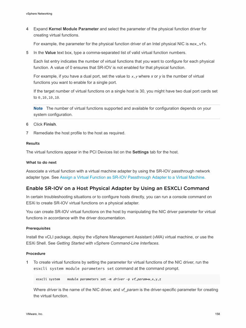
4 Expand Kernel Module Parameter and select the parameter of the physical function driver for creating virtual functions.
For example, the parameter for the physical function driver of an Intel physical NIC is max_vfs.
5 In the Value text box, type a comma-separated list of valid virtual function numbers.
Each list entry indicates the number of virtual functions that you want to configure for each physical function. A value of 0 ensures that SR-IOV is not enabled for that physical function.
For example, if you have a dual port, set the value to x,y where x or y is the number of virtual functions you want to enable for a single port.
If the target number of virtual functions on a single host is 30, you might have two dual port cards set to 0,10,10,10.
Note The number of virtual functions supported and available for configuration depends on your system configuration.
6 Click Finish.
7 Remediate the host profile to the host as required.
Results
The virtual functions appear in the PCI Devices list on the Settings tab for the host.
What to do next
Associate a virtual function with a virtual machine adapter by using the SR-IOV passthrough network adapter type. See Assign a Virtual Function as SR-IOV Passthrough Adapter to a Virtual Machine.
Enable SR-IOV on a Host Physical Adapter by Using an ESXCLI CommandIn certain troubleshooting situations or to configure hosts directly, you can run a console command on ESXi to create SR-IOV virtual functions on a physical adapter.
You can create SR-IOV virtual functions on the host by manipulating the NIC driver parameter for virtual functions in accordance with the driver documentation.
Prerequisites
Install the vCLI package, deploy the vSphere Management Assistant (vMA) virtual machine, or use the ESXi Shell. See Getting Started with vSphere Command-Line Interfaces.
Procedure
1 To create virtual functions by setting the parameter for virtual functions of the NIC driver, run the esxcli system module parameters set command at the command prompt.
esxcli system module parameters set -m driver -p vf_param=w,x,y,z
Where driver is the name of the NIC driver, and vf_param is the driver-specific parameter for creating the virtual function.
vSphere Networking
VMware, Inc. 158

You can use a comma-separated list to set values for the vf_param parameter, where each entry indicates the number of virtual functions for a port. A value of 0 ensures that SR-IOV is not enabled for that physical function.
If you have two dual port NICs, you can set the value to w,x,y,z, where w,x,y, and z is the number of virtual functions you want to enable for a single port. For example, to create 30 virtual functions distributed on two dual port Intel cards by using the ixgbe driver, run the following command for the ixgbe driver and the max_vfs parameter:
esxcli system module parameters set -m ixgbe -p max_vfs=0,10,10,10
2 Restart the host to create the virtual functions.
What to do next
Associate a virtual function with a virtual machine adapter by using the SR-IOV passthrough network adapter type. See Assign a Virtual Function as SR-IOV Passthrough Adapter to a Virtual Machine.
Virtual Machine That Uses an SR-IOV Virtual Function Fails to Power On Because the Host Is Out of Interrupt VectorsOn an ESXi host, one or more virtual machines that use SR-IOV virtual functions (VFs) for networking are powered off.
Problem
On an ESXi host, one or more virtual machines that use SR-IOV virtual functions (VFs) for networking fail to power on if the total number of assigned virtual functions is close to the maximum number of VFs specified in the vSphere Configuration Maximums guide.
The virtual machine log file vmware.log contains the following message about the VF:
PCIPassthruChangeIntrSettings: vf_name failed to register interrupt (error code 195887110)
The VMkernel log file vmkernel.log contains the following messages about the VF assigned to the virtual machine:
VMKPCIPassthru: 2565: BDF = vf_name intrType = 4 numVectors: 3
WARNING: IntrVector: 233: Out of interrupt vectors
Cause
The number of allocatable interrupt vectors scales up with the number of physical CPUs on an ESXi host. An ESXi host that has 32 CPUs can provide a total of 4096 interrupt vectors. When the host boots, devices on the host such as storage controllers, physical network adapters, and USB controllers consume a subset of the 4096 vectors. If these devices require more than 1024 vectors, the maximum number of potentially supported VFs is reduced.
vSphere Networking
VMware, Inc. 159
When a virtual machine powers on and the guest operating system VF driver starts, interrupt vectors are consumed. If the required number of interrupt vectors is not available, the guest operating system shuts down unexpectedly without any error messages.
No rule presently exists to determine the number of interrupt vectors consumed or available on a host. This number depends on the hardware configuration of the host.
Solution
u To be able to power on the virtual machines, reduce the total number of VFs assigned to virtual machines on the host.
For example, change the SR-IOV network adapter of a virtual machine to an adapter that is connected to a vSphere Standard Switch or vSphere Distributed Switch.
Remote Direct Memory Access for Virtual MachinesvSphere 6.5 and later releases support remote direct memory access (RDMA) communication between virtual machines that have paravirtualized RDMA (PVRDMA) network adapters .
Overview of RDMARDMA allows direct memory access from the memory of one computer to the memory of another computer without involving the operating system or CPU . The transfer of memory is offloaded to the RDMA-capable Host Channel Adapters (HCA) . A PVRDMA network adapter provides remote direct memory access in a virtual environment.
Using RDMA in vSphereIn vSphere, a virtual machine can use a PVRDMA network adapter to communicate with other virtual machines that have PVRDMA devices . The virtual machines must be connected to the same vSphere Distributed Switch.
The PVRDMA device automatically selects the method of communication between the virtual machines . For virtual machines that run on the same ESXi host with or without a physical RDMA device, the data transfer is a memcpy between the two virtual machines . The physical RDMA hardware is not used in this case .
For virtual machines that reside on different ESXi hosts and that have a physical RDMA connection, the physical RDMA devices must be uplinks on the distributed switch. In this case, the communication between the virtual machines by way of PVRDMA uses the underlying physical RDMA devices.
For two virtual machines that run on different ESXi hosts, when at least one of the hosts does not have a physical RDMA device, the communication falls back to a TCP-based channel and the performance is reduced.
PVRDMA SupportvSphere 6.5 and later supports PVRDMA only in environments with specific configuration.
vSphere Networking
VMware, Inc. 160
Supported ConfigurationsTo use PVRDMA in vSphere 6.5, your environment must meet several configuration requirements.
Table 10-3. Supported Configurations for Using PVRDMA
Component Requirements
vSphere n ESXi host 6.5 or later.
n vCenter Server or vCenter Server Appliance 6.5 or later.
n vSphere Distributed Switch.
Physical host n Must be compatible with the ESXi release.
Host Channel Adapter (HCA) n Must be compatible with the ESXi release.
Note Virtual machines that reside on different ESXi hosts require HCA to use RDMA . You must assign the HCA as an uplink for the vSphere Distributed Switch. PVRDMA does not support NIC teaming. The HCA must be the only uplink on the vSphere Distributed Switch.
For virtual machines on the same ESXi hosts or virtual machines using the TCP-based fallback, the HCA is not required.
Virtual machine n Virtual hardware verison 13 or later.
Guest OS n Linux (64-bit)
To verify that your physical hosts and HCAs are compatible with ESXi releases, see the VMware Compatibility Guide.
Note Attempts to enable or configure unsupported features with PVRDMA in the vSphere Web Client might result in unexpected behavior in your environment.
Configure an ESXi Host for PVRDMAConfigure the VMkernel adapter and firewall rule of an ESXi host for PVRDMA communication.
Prerequisites
Verify that your ESXi host meets the requirements for PVRDMA. See PVRDMA Support.
n Tag a VMkernel Adapter for PVRDMA
Select a VMkernel adapter and enable it for PVRDMA communication.
n Enable the Firewall Rule for PVRDMA
Enable the firewall rule for PVRDMA in the security profile of the ESXi host.
Tag a VMkernel Adapter for PVRDMASelect a VMkernel adapter and enable it for PVRDMA communication.
Procedure
1 In the vSphere Web Client, navigate to the host.
vSphere Networking
VMware, Inc. 161
2 On the Configure tab, expand System.
3 Click Advanced System Settings.
4 Locate Net.PVRDMAVmknic and click Edit.
5 Enter the value of the VMkernel adapter that you want to use, for example vmk0, and click OK .
Enable the Firewall Rule for PVRDMAEnable the firewall rule for PVRDMA in the security profile of the ESXi host.
Procedure
1 In the vSphere Web Client, navigate to the host.
2 On the Configure tab, expand System.
3 Click Security Profile.
4 In the Firewall section, click Edit.
5 Scroll to the pvrdma rule and select the check box next to it.
6 Click OK.
Assign a PVRDMA Adapter to a Virtual MachineTo enable a virtual machine to exchange data by using RDMA, you must associate the virtual machine with a PVRDMA network adapter.
Prerequisites
n Verify that the host on which the virtual machine is running is configured for RDMA. See Configure an ESXi Host for PVRDMA.
n Verify that the host is connected to a vSphere Distributed Switch.
n Verify that the virtual machine uses virtual hardware version 13.
n Verify that the guest operating system is a Linux 64-bit distribution.
Procedure
1 Locate the virtual machine in the vSphere Web Client.
a Select a data center, folder, cluster, resource pool, or host and click the VMs tab.
b Click Virtual Machines and double-click the virtual machine from the list.
2 Power off the virtual machine.
3 On the Configure tab of the virtual machine, expand Settings and select VM Hardware.
4 Click Edit and select the Virtual Hardware tab in the dialog box displaying the settings.
5 From the New device drop-down menu, select Network and click Add.
6 Expand the New Network section and connect the virtual machine to a distributed port group.
vSphere Networking
VMware, Inc. 162
7 From the Adapter type drop-down menu, select PVRDMA.
8 Expand the Memory section, select Reserve all guest memory (All locked), and click OK .
9 Power on the virtual machine.
Network Requirements for RDMA over Converged EthernetRDMA over Converged Ethernet ensures low-latency, light-weight, and high-throughput RDMA communication over an Ethernet network. RoCE requires a network that is configured for lossless traffic of information at layer 2 alone or at both layer 2 and layer 3.
RDMA over Converged Ethernet (RoCE) is a network protocol that uses RDMA to provide faster data transfer for network-intensive applications. RoCE allows direct memory transfer between hosts without involving the hosts' CPUs.
There are two versions of the RoCE protocol. RoCE v1 operates at the link network layer (layer 2). RoCE v2 operates at the Internet network layer (layer 3) . Both RoCE v1 and RoCE v2 require a lossless network configuration. RoCE v1 requires a lossless layer 2 network, and RoCE v2 requires that both layer 2 and layer 3 are configured for lossless operation.
Lossless Layer 2 NetworkTo ensure lossless layer 2 environment, you must be able to control the traffic flows. Flow control is achieved by enabling global pause across the network or by using the Priority Flow Control (PFC) protocol defined by Data Center Bridging group (DCB). PFC is a layer 2 protocol that uses the class of services field of the 802.1Q VLAN tag to set individual traffic priorities. It puts on pause the transfer of packets towards a receiver in accordance with the individual class of service priorities. This way, a single link carries both lossless RoCE traffic and other lossy, best-effort traffic. In case of traffic flow congestion, important lossy traffic can be affected. To isolate different flows from one another, use RoCE in a PFC priority-enabled VLAN.
Lossless Layer 3 NetworkRoCE v2 requires that lossless data transfer is preserved at layer 3 routing devices. To enable the transfer of layer 2 PFC lossless priorities across layer 3 routers, configure the router to map the received priority setting of a packet to the corresponding Differentiated Serviced Code Point (DSCP) QoS setting that operates at layer 3. The transferred RDMA packets are marked with layer 3 DSCP, layer 2 Priority Code Points (PCP) or with both. Routers use either DSCP or PCP to extract priority information from the packet. In case PCP is used, the packet must be VLAN-tagged and the router must copy the PCP bits of the tag and forward them to the next network. If the packet is marked with DSCP, the router must keep the DSCP bits unchanged.
Like RoCE v1, RoCE v2 must run on a PFC priority-enabled VLAN.
Note Do not team RoCE NICs, if you intend to use RDMA on those NICs.
For vendor-specific configuration information, refer to the official documentation of the respective device or switch vendor.
vSphere Networking
VMware, Inc. 163

Jumbo FramesJumbo frames let ESXi hosts send larger frames out onto the physical network. The network must support jumbo frames end-to-end that includes physical network adapters, physical switches, and storage devices.
Before enabling jumbo frames, check with your hardware vendor to ensure that your physical network adapter supports jumbo frames.
You can enable jumbo frames on a vSphere distributed switch or vSphere standard switch by changing the maximum transmission unit (MTU) to a value greater than 1500 bytes. 9000 bytes is the maximum frame size that you can configure.
Enable Jumbo Frames on a vSphere Distributed SwitchEnable jumbo frames for the entire traffic that passes through a vSphere Distributed Switch.
Important When you change the MTU size of a vSphere Distributed Switch, the physical NICs that are assigned as uplinks are brought down and up again. This causes a short network outage of between 5 to 10 milliseconds for virtual machines or services that are using the uplinks.
Procedure
1 In the vSphere Web Client, navigate to the distributed switch.
2 On the Configure tab, expand Settings and select Properties.
3 Click Edit.
4 Click Advanced and set the MTU property to a value greater than 1500 bytes.
You cannot set the MTU size to a value greater than 9000 bytes.
5 Click OK.
Enable Jumbo Frames on a vSphere Standard SwitchEnable jumbo frames for all traffic through a vSphere Standard Switch on a host.
Procedure
1 In the vSphere Web Client, navigate to the host.
2 On the Configure tab, expand Networking and select Virtual switches.
3 Select a standard switch from the virtual switch table and click Edit settings.
4 In the Properties section, set the MTU property to a value greater than 1500 bytes.
You can increase the MTU size up to 9000 bytes.
5 Click OK.
vSphere Networking
VMware, Inc. 164
Enable Jumbo Frames for a VMkernel AdapterJumbo frames reduce the CPU load caused by transferring data. Enable jumbo frames on a VMkernel adapter by changing the maximum transmission units (MTU) of the adapter.
Procedure
1 In the vSphere Web Client, navigate to the host.
2 On the Configure tab, expand Networking and select VMkernel adapters.
3 Select a VMkernel adapter from the adapter table.
The properties of the adapter appear.
4 Click the name of the VMkernel adapter.
5 Click Edit.
6 Select NIC settings and set the MTU property to a value greater than 1500.
You can increase the MTU size up to 9000 bytes.
7 Click OK.
Enable Jumbo Frame Support on a Virtual MachineEnabling jumbo frame support on a virtual machine requires an enhanced VMXNET adapter for that virtual machine.
Procedure
1 Locate the virtual machine in the vSphere Web Client.
a Select a data center, folder, cluster, resource pool, or host and click the VMs tab.
b Click Virtual Machines and double-click the virtual machine from the list.
2 On the Configure tab of the virtual machine, expand Settings and select VM Hardware.
3 Click Edit and select the Virtual Hardware tab in the dialog box displaying the settings.
4 Expand the Network adapter section. Record the network settings and MAC address that the network adapter is using.
5 Click Remove to remove the network adapter from the virtual machine.
6 From the New device drop-down menu, select Network and click Add.
7 From the Adapter Type drop-down menu, select VMXNET 2 (Enhanced) or VMXNET 3.
8 Set the network settings to the ones recorded for the old network adapter.
9 Set the MAC Address to Manual, and type the MAC address that the old network adapter was using.
10 Click OK.
vSphere Networking
VMware, Inc. 165
What to do next
n Check that the enhanced VMXNET adapter is connected to a standard switch or to a distributed switch with jumbo frames enabled.
n Inside the guest operating system, configure the network adapter to allow jumbo frames. See the documentation of your guest operating system.
n Configure all physical switches and any physical or virtual machines to which this virtual machine connects to support jumbo frames.
TCP Segmentation OffloadUse TCP Segmentation Offload (TSO) in VMkernel network adapters and virtual machines to improve the network performance in workloads that have severe latency requirements.
TSO on the transmission path of physical network adapters, and VMkernel and virtual machine network adapters improves the performance of ESXi hosts by reducing the overhead of the CPU for TCP/IP network operations. When TSO is enabled, the network adapter divides larger data chunks into TCP segments instead of the CPU. The VMkernel and the guest operating system can use more CPU cycles to run applications.
To benefit from the performance improvement that TSO provides, enable TSO along the data path on an ESXi host including physical network adapters, VMkernel and guest operating system. By default, TSO is enabled in the VMkernel of the ESXi host , and in the VMXNET 2 and VMXNET 3 virtual machine adapters.
For information about the location of TCP packet segmentation in the data path, see VMware Knowledge Base article Understanding TCP Segmentation Offload (TSO) and Large Receive Offload (LRO) in a VMware environment.
Enable or Disable Software TSO in the VMkernelIf a physical network adapter experiences problems with TSO, you can temporarily enable the software simulation of TSO in the VMkernel until you troubleshoot the problems.
Procedure
u Run these esxcli network nic software set console commands to enable or disable the software simulation of TSO in the VMkernel.
n Enable the software simulation of TSO in the VMkernel.
esxcli network nic software set --ipv4tso=1 -n vmnicX
esxcli network nic software set --ipv6tso=1 -n vmnicX
n Disable the software simulation of TSO in the VMkernel.
esxcli network nic software set --ipv4tso=0 -n vmnicX
esxcli network nic software set --ipv6tso=0 -n vmnicX
vSphere Networking
VMware, Inc. 166
where X in vmnicX represents the number of the NIC ports on the host.
The configuration change persists across host reboots.
Determine Whether TSO Is Supported on the Physical Network Adapters on an ESXi HostExamine whether a physical network adapter offloads TCP/IP packet segmentation when you estimate the networking performance on a host that runs latency-sensitive workloads. If a physical network adapter supports TSO, then TSO is enabled by default.
Procedure
u Run the following console command to determine whether TSO is enabled on the physical network adapters on a host.
esxcli network nic tso get
Enable or Disable TSO on an ESXi HostEnable TCP Segmentation Offload (TSO) on the transmission path to have the NIC divide larger data chunks into TCP segments. Disable TSO to have CPU perform TCP segmentation.
By default, a host uses hardware TSO if its physical adapters support it.
Procedure
1 In the vSphere Web Client, navigate to the host.
2 On the Configure tab, expand System.
3 Click Advanced System Settings.
4 Edit the value of the Net.UseHwTSO parameter for IPv4 and of Net.UseHwTSO6 for IPv6.
n To enable TSO, set Net.UseHwTSO and Net.UseHwTSO6 to 1.
n To disable TSO, set Net.UseHwTSO and Net.UseHwTSO6 to 0.
5 Click OK to apply the changes.
6 To reload the driver module of the physical adapter, run the esxcli system module set console command in the ESXi Shell on the host.
a To disable the driver, run the esxcli system module set command with the --enabled false option.
esxcli system module set --enabled false --module nic_driver_module
b To enable the driver, run the esxcli system module set command with the --enabled true option.
esxcli system module set --enabled true --module nic_driver_module
vSphere Networking
VMware, Inc. 167
Results
If a physical adapter does not support hardware TSO, the VMkernel segments large TCP packets coming from the guest operating system and sends them to the adapter.
Determine Whether TSO Is Enabled on an ESXi HostExamine whether hardware TSO is enabled in the VMkernel when you estimate the networking performance on a host that runs latency-sensitive workloads. By default, hardware TSO is enabled on an ESXi host.
Procedure
1 In the vSphere Web Client, navigate to the host.
2 On the Configure tab, expand System.
3 Click Advanced System Settings.
4 Examine the value of the Net.UseHwTSO and Net.UseHwTSO6 parameters.
Net.UseHwTSO shows the TSO state for IPv4, and Net.UseHwTSO6 for IPv6. TSO is enabled if the property is set to 1.
Enable or Disable TSO on a Linux Virtual MachineEnable TSO support on the network adapter of a Linux virtual machine so that the guest operating system redirects TCP packets that need segmentation to the VMkernel.
Prerequisites
n Verify that ESXi supports the Linux guest operating system.
See the VMware Compatibility Guide documentation.
n Verify that the network adapter on the Linux virtual machine is VMXNET2 or VMXNET3.
Procedure
u In a terminal window on the Linux guest operating system, to enable or disable TSO, run the ethtool command with the -K and tso options.
n To enable TSO, run the following command:
ethtool -K ethY tso on
n To disable TSO, run the following command:
ethtool -K ethY tso off
where Y in ethY is the sequence number of the NIC in the virtual machine.
vSphere Networking
VMware, Inc. 168
Enable or Disable TSO on a Windows Virtual MachineBy default, TSO is enabled on a Windows virtual machine on VMXNET2 and VXMNET3 network adapters. For performance reasons, you might want to disable TSO.
Prerequisites
n Verify that ESXi supports the Windows guest operating system. See the VMware Compatibility Guide documentation.
n Verify that the network adapter on the Windows virtual machine is VMXNET2 or VMXNET3.
Procedure
1 In the Network and Sharing Center on the Windows control panel, click the name of the network adapter.
2 Click its name.
A dialog box displays the status of the adapter.
3 Click Properties, and beneath the network adapter type, click Configure.
4 On the Advanced tab, set the Large Send Offload V2 (IPv4) and Large Send Offload V2 (IPv6) properties to Enabled or Disabled.
5 Click OK.
6 Restart the virtual machine.
Large Receive OffloadUse Large Receive Offload (LRO) to reduce the CPU overhead for processing packets that arrive from the network at a high rate.
LRO reassembles incoming network packets into larger buffers and transfers the resulting larger but fewer packets to the network stack of the host or virtual machine. The CPU has to process fewer packets than when LRO is disabled, which reduces its utilization for networking especially in the case of connections that have high bandwidth.
To benefit from the performance improvement of LRO, enable LRO along the data path on an ESXi host including VMkernel and guest operating system. By default, LRO is enabled in the VMkernel and in the VMXNET3 virtual machine adapters.
For information about the location of TCP packet aggregation in the data path, see VMware Knowledge Base article Understanding TCP Segmentation Offload (TSO) and Large Receive Offload (LRO) in a VMware environment.
Enable Hardware LRO for All VMXNET3 Adapters on an ESXi HostEnable the hardware capabilities of host physical adapters to aggregate incoming TCP packets for VXMNET3 VM adapters by using the LRO technology instead of consuming resources for assembling in the guest operating system.
vSphere Networking
VMware, Inc. 169

Procedure
1 In the vSphere Web Client, navigate to the host.
2 On the Configure tab, expand System.
3 Click Advanced System Settings.
4 Edit the value of the Net.Vmxnet3HwLRO parameter.
n To enable hardware LRO, set Net.Vmxnet3HwLRO to 1.
n To disable hardware LRO, set Net.Vmxnet3HwLRO to 0.
5 Click OK to apply the changes.
Enable or Disable Software LRO for All VMXNET3 Adapters on an ESXi HostUse software LRO in the VMkernel backend of VMXNET3 adapters to improve networking performance of virtual machines if the host physical adapters do not support hardware LRO.
vSphere supports software LRO for both IPv4 and IPv6 packets.
Prerequisites
Procedure
1 In the vSphere Web Client, navigate to the host.
2 On the Configure tab, expand System.
3 Click Advanced System Settings.
4 Edit the value of the Net.Vmxnet3SwLRO parameter for VMXNET3 adapters.
n To enable software LRO, set Net.Vmxnet3SwLRO to 1.
n To disable software LRO, set Net.Vmxnet3SwLRO to 0.
5 Click OK to apply the changes.
Determine Whether LRO Is Enabled for VMXNET3 Adapters on an ESXi HostExamine the status of LRO on an ESXi when you estimate the networking performance on a host that runs latency-sensitive workloads.
Prerequisites
Procedure
1 In the vSphere Web Client, navigate to the host.
2 On the Configure tab, expand System.
vSphere Networking
VMware, Inc. 170
3 Click Advanced System Settings.
4 Examine the value of the LRO parameters for VMXNET2 and VMXNET3.
n For hardware LRO, examine the Net.Vmxnet3HwLRO parameter. If it is equal to 1, hardware LRO is enabled.
n For software LRO, examine the Net.Vmxnet3SwLRO parameter. If it is equal to 1, hardware LRO is enabled.
Change the Size of the LRO Buffer for VMXNET 3 AdaptersYou can change the size of the buffer for packet aggregation for virtual machine connections through VMXNET 3 network adapters. Increase the buffer size to reduce the number of TCP acknowledgments and improve efficiency in workloads.
Procedure
1 In the vSphere Web Client, navigate to the host.
2 On the Configure tab, expand System.
3 Click Advanced System Settings.
4 Enter a value between 1 and 65535 for the Net.VmxnetLROMaxLength parameter to set the LRO buffer size in bytes.
By default the size of the LRO buffer is equal to 32000 bytes.
Enable or Disable LRO for All VMkernel Adapters on an ESXi HostUse LRO in the VMkernel network adapters on an ESXi host to improve the networking performance for incoming infrastructure traffic.
Procedure
1 In the vSphere Web Client, navigate to the host.
2 On the Configure tab, expand System.
3 Click Advanced System Settings.
4 Edit the value of the Net.TcpipDefLROEnabled parameter.
n To enable LRO for the VMkernel network adapters on the host, set Net.TcpipDefLROEnabled to 1.
n To disable software LRO for the VMkernel network adapters on the host, set Net.TcpipDefLROEnabled to 0.
5 Click OK to apply the changes.
vSphere Networking
VMware, Inc. 171
Change the Size of the LRO Buffer for VMkernel AdaptersYou can change the size of the buffer for packet aggregation for VMkernel connections. Increase the buffer size to reduce the number of TCP acknowledgments and improve efficiency in the VMkernel.
Procedure
1 In the vSphere Web Client, navigate to the host.
2 On the Configure tab, expand System.
3 Click Advanced System Settings.
4 Enter a value between 1 and 65535 for the Net.TcpipDefLROMaxLength parameter to set the LRO buffer size in bytes.
By default the size of the LRO buffer is equal to 32768 bytes.
Enable or Disable LRO on a VMXNET3 Adapter on a Linux Virtual MachineIf LRO is enabled for VMXNET3 adapters on the host, activate LRO support on a network adapter on a Linux virtual machine to ensure that the guest operating system does not spend resources to aggregate incoming packets into larger buffers.
Prerequisites
Verify that the Linux kernel is 2.6.24 and later.
Procedure
u In a terminal window on the Linux guest operating system, run the ethtool command with the -K and lro options.
n To enable LRO, run the following command:
ethtool -K ethY lro on
where Y in ethY is the sequence number of the NIC in the virtual machine.
n To disable LRO, run the following command:
ethtool -K ethY lro off
where Y in ethY is the sequence number of the NIC in the virtual machine.
Enable or Disable LRO on a VMXNET3 Adapter on a Windows Virtual MachineIf LRO is enabled for VMXNET3 adapters on the host, activate LRO support on a network adapter on a Windows virtual machine to ensure that the guest operating system does not spend resources to aggregate incoming packets into larger buffers.
On Windows, the LRO technology is also referred to as Receive Side Coalescing (RSC).
vSphere Networking
VMware, Inc. 172
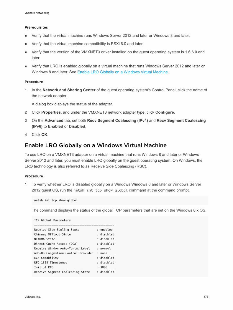
Prerequisites
n Verify that the virtual machine runs Windows Server 2012 and later or Windows 8 and later.
n Verify that the virtual machine compatibility is ESXi 6.0 and later.
n Verify that the version of the VMXNET3 driver installed on the guest operating system is 1.6.6.0 and later.
n Verify that LRO is enabled globally on a virtual machine that runs Windows Server 2012 and later or Windows 8 and later. See Enable LRO Globally on a Windows Virtual Machine.
Procedure
1 In the Network and Sharing Center of the guest operating system's Control Panel, click the name of the network adapter.
A dialog box displays the status of the adapter.
2 Click Properties, and under the VMXNET3 network adapter type, click Configure.
3 On the Advanced tab, set both Recv Segment Coalescing (IPv4) and Recv Segment Coalescing (IPv6) to Enabled or Disabled.
4 Click OK.
Enable LRO Globally on a Windows Virtual MachineTo use LRO on a VMXNET3 adapter on a virtual machine that runs Windows 8 and later or Windows Server 2012 and later, you must enable LRO globally on the guest operating system. On Windows, the LRO technology is also referred to as Receive Side Coalescing (RSC).
Procedure
1 To verify whether LRO is disabled globally on a Windows Windows 8 and later or Windows Server 2012 guest OS, run the netsh int tcp show global command at the command prompt.
netsh int tcp show global
The command displays the status of the global TCP parameters that are set on the Windows 8.x OS.
TCP Global Parameters
----------------------------------------------
Receive-Side Scaling State : enabled
Chimney Offload State : disabled
NetDMA State : disabled
Direct Cache Access (DCA) : disabled
Receive Window Auto-Tuning Level : normal
Add-On Congestion Control Provider : none
ECN Capability : disabled
RFC 1323 Timestamps : disabled
Initial RTO : 3000
Receive Segment Coalescing State : disabled
vSphere Networking
VMware, Inc. 173
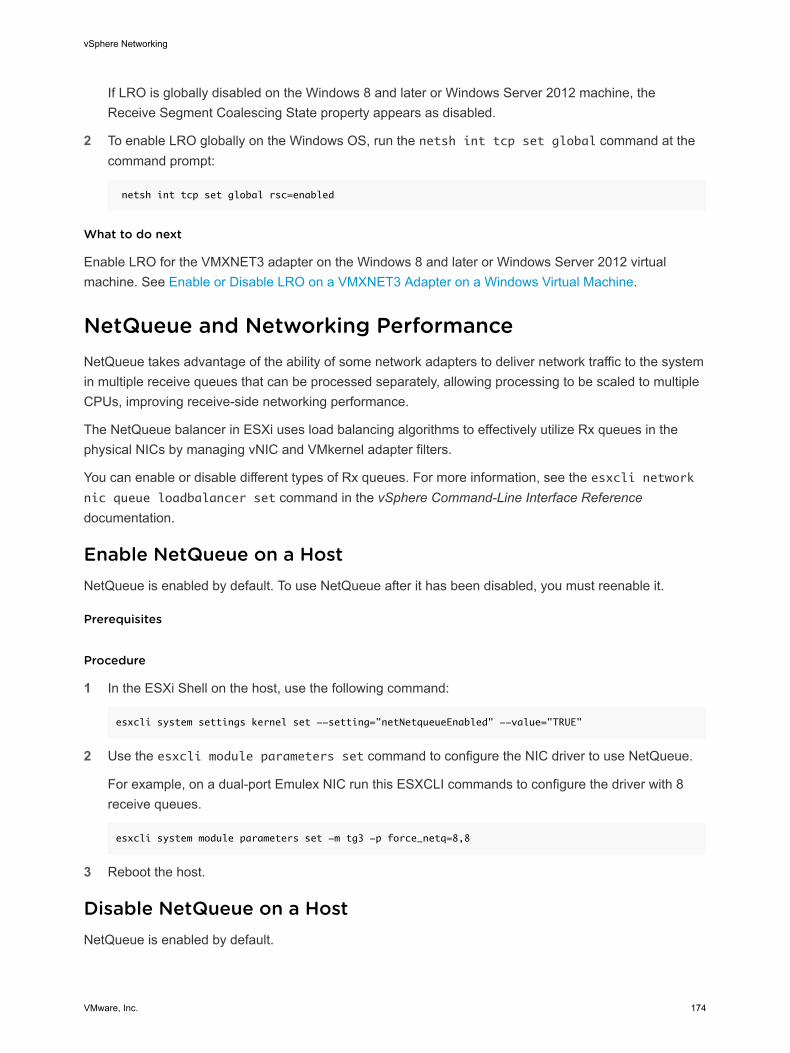
If LRO is globally disabled on the Windows 8 and later or Windows Server 2012 machine, the Receive Segment Coalescing State property appears as disabled.
2 To enable LRO globally on the Windows OS, run the netsh int tcp set global command at the command prompt:
netsh int tcp set global rsc=enabled
What to do next
Enable LRO for the VMXNET3 adapter on the Windows 8 and later or Windows Server 2012 virtual machine. See Enable or Disable LRO on a VMXNET3 Adapter on a Windows Virtual Machine.
NetQueue and Networking PerformanceNetQueue takes advantage of the ability of some network adapters to deliver network traffic to the system in multiple receive queues that can be processed separately, allowing processing to be scaled to multiple CPUs, improving receive-side networking performance.
The NetQueue balancer in ESXi uses load balancing algorithms to effectively utilize Rx queues in the physical NICs by managing vNIC and VMkernel adapter filters.
You can enable or disable different types of Rx queues. For more information, see the esxcli network nic queue loadbalancer set command in the vSphere Command-Line Interface Reference documentation.
Enable NetQueue on a HostNetQueue is enabled by default. To use NetQueue after it has been disabled, you must reenable it.
Prerequisites
Procedure
1 In the ESXi Shell on the host, use the following command:
esxcli system settings kernel set --setting="netNetqueueEnabled" --value="TRUE"
2 Use the esxcli module parameters set command to configure the NIC driver to use NetQueue.
For example, on a dual-port Emulex NIC run this ESXCLI commands to configure the driver with 8 receive queues.
esxcli system module parameters set -m tg3 -p force_netq=8,8
3 Reboot the host.
Disable NetQueue on a HostNetQueue is enabled by default.
vSphere Networking
VMware, Inc. 174
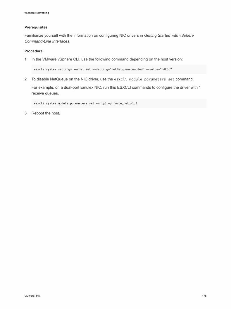
Prerequisites
Familiarize yourself with the information on configuring NIC drivers in Getting Started with vSphere Command-Line Interfaces.
Procedure
1 In the VMware vSphere CLI, use the following command depending on the host version:
esxcli system settings kernel set --setting="netNetqueueEnabled" --value="FALSE"
2 To disable NetQueue on the NIC driver, use the esxcli module parameters set command.
For example, on a dual-port Emulex NIC, run this ESXCLI commands to configure the driver with 1 receive queues.
esxcli system module parameters set -m tg3 -p force_netq=1,1
3 Reboot the host.
vSphere Networking
VMware, Inc. 175
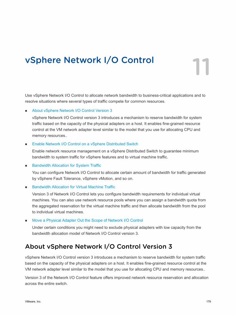
vSphere Network I/O Control 11Use vSphere Network I/O Control to allocate network bandwidth to business-critical applications and to resolve situations where several types of traffic compete for common resources.
n About vSphere Network I/O Control Version 3
vSphere Network I/O Control version 3 introduces a mechanism to reserve bandwidth for system traffic based on the capacity of the physical adapters on a host. It enables fine-grained resource control at the VM network adapter level similar to the model that you use for allocating CPU and memory resources..
n Enable Network I/O Control on a vSphere Distributed Switch
Enable network resource management on a vSphere Distributed Switch to guarantee minimum bandwidth to system traffic for vSphere features and to virtual machine traffic.
n Bandwidth Allocation for System Traffic
You can configure Network I/O Control to allocate certain amount of bandwidth for traffic generated by vSphere Fault Tolerance, vSphere vMotion, and so on.
n Bandwidth Allocation for Virtual Machine Traffic
Version 3 of Network I/O Control lets you configure bandwidth requirements for individual virtual machines. You can also use network resource pools where you can assign a bandwidth quota from the aggregated reservation for the virtual machine traffic and then allocate bandwidth from the pool to individual virtual machines.
n Move a Physical Adapter Out the Scope of Network I/O Control
Under certain conditions you might need to exclude physical adapters with low capacity from the bandwidth allocation model of Network I/O Control version 3.
About vSphere Network I/O Control Version 3vSphere Network I/O Control version 3 introduces a mechanism to reserve bandwidth for system traffic based on the capacity of the physical adapters on a host. It enables fine-grained resource control at the VM network adapter level similar to the model that you use for allocating CPU and memory resources..
Version 3 of the Network I/O Control feature offers improved network resource reservation and allocation across the entire switch.
VMware, Inc. 176
Models for Bandwidth Resource ReservationNetwork I/O Control version 3 supports separate models for resource management of system traffic related to infrastructure services, such as vSphere Fault Tolerance, and of virtual machines.
The two traffic categories have different nature. System traffic is strictly associated with an ESXi host. The network traffic routes change when you migrate a virtual machine across the environment. To provide network resources to a virtual machine regardless of its host, in Network I/O Control you can configure resource allocation for virtual machines that is valid in the scope of the entire distributed switch.
Bandwidth Guarantee to Virtual MachinesNetwork I/O Control version 3 provisions bandwidth to the network adapters of virtual machines by using constructs of shares, reservation and limit. Based on these constructs, to receive sufficient bandwidth, virtualized workloads can rely on admission control in vSphere Distributed Switch, vSphere DRS and vSphere HA. See Admission Control for Virtual Machine Bandwidth.
Availability of FeaturesSR-IOV is not available for virtual machines configured to use Network I/O Control version 3.
Enable Network I/O Control on a vSphere Distributed SwitchEnable network resource management on a vSphere Distributed Switch to guarantee minimum bandwidth to system traffic for vSphere features and to virtual machine traffic.
Procedure
1 In the vSphere Web Client, navigate to the distributed switch.
2 From the Actions menu, select Edit Settings.
3 From the Network I/O Control drop-down menu, select Enable.
4 Click OK.
Results
When enabled, the model that Network I/O Control uses to handle bandwidth allocation for system traffic and virtual machine traffic is based on the Network I/O Control version that is active on the distributed switch. See About vSphere Network I/O Control Version 3.
Bandwidth Allocation for System TrafficYou can configure Network I/O Control to allocate certain amount of bandwidth for traffic generated by vSphere Fault Tolerance, vSphere vMotion, and so on.
vSphere Networking
VMware, Inc. 177
You can use Network I/O Control on a distributed switch to configure bandwidth allocation for the traffic that is related to the main vSphere features:
n Management
n Fault Tolerance
n NFS
n vSAN
n vMotion
n vSphere Replication
n vSphere Data Protection Backup
n Virtual machine
vCenter Server propagates the allocation from the distributed switch to each physical adapter on the hosts that are connected to the switch.
n Bandwidth Allocation Parameters for System Traffic
By using several configuration parameters Network I/O Control allocates bandwidth to traffic from basic vSphere system features.
n Example Bandwidth Reservation for System Traffic
The capacity of the physical adapters determines the bandwidth that you guarantee. According to this capacity, you can guarantee minimum bandwidth to a system feature for its optimal operation.
n Configure Bandwidth Allocation for System Traffic
Assign bandwidth for host management, virtual machines, NFS storage, vSphere vMotion, vSphere Fault Tolerance, vSAN, and vSphere Replication on the physical adapters that are connected to a vSphere Distributed Switch.
Bandwidth Allocation Parameters for System TrafficBy using several configuration parameters Network I/O Control allocates bandwidth to traffic from basic vSphere system features.
vSphere Networking
VMware, Inc. 178
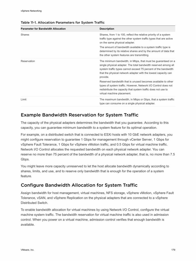
Table 11-1. Allocation Parameters for System Traffic
Parameter for Bandwidth Allocation Description
Shares Shares, from 1 to 100, reflect the relative priority of a system traffic type against the other system traffic types that are active on the same physical adapter.
The amount of bandwidth available to a system traffic type is determined by its relative shares and by the amount of data that the other system features are transmitting.
Reservation The minimum bandwidth, in Mbps, that must be guaranteed on a single physical adapter. The total bandwidth reserved among all system traffic types cannot exceed 75 percent of the bandwidth that the physical network adapter with the lowest capacity can provide.
Reserved bandwidth that is unused becomes available to other types of system traffic. However, Network I/O Control does not redistribute the capacity that system traffic does not use to virtual machine placement.
Limit The maximum bandwidth, in Mbps or Gbps, that a system traffic type can consume on a single physical adapter.
Example Bandwidth Reservation for System TrafficThe capacity of the physical adapters determines the bandwidth that you guarantee. According to this capacity, you can guarantee minimum bandwidth to a system feature for its optimal operation.
For example, on a distributed switch that is connected to ESXi hosts with 10 GbE network adapters, you might configure reservation to guarantee 1 Gbps for management through vCenter Server, 1 Gbps for vSphere Fault Tolerance, 1 Gbps for vSphere vMotion traffic, and 0.5 Gbps for virtual machine traffic. Network I/O Control allocates the requested bandwidth on each physical network adapter. You can reserve no more than 75 percent of the bandwidth of a physical network adapter, that is, no more than 7.5 Gbps.
You might leave more capacity unreserved to let the host allocate bandwidth dynamically according to shares, limits, and use, and to reserve only bandwidth that is enough for the operation of a system feature.
Configure Bandwidth Allocation for System TrafficAssign bandwidth for host management, virtual machines, NFS storage, vSphere vMotion, vSphere Fault Tolerance, vSAN, and vSphere Replication on the physical adapters that are connected to a vSphere Distributed Switch.
To enable bandwidth allocation for virtual machines by using Network I/O Control, configure the virtual machine system traffic. The bandwidth reservation for virtual machine traffic is also used in admission control. When you power on a virtual machine, admission control verifies that enough bandwidth is available.
vSphere Networking
VMware, Inc. 179
Prerequisites
n Verify that vSphere Distributed Switch is version 6.0.0 and later.
n Verify that Network I/O Control on the switch is version 3.
n Verify that Network I/O Control is enabled. See Enable Network I/O Control on a vSphere Distributed Switch.
Procedure
1 In the vSphere Web Client, navigate to the distributed switch.
2 On the Configure tab, expand Resource Allocation.
3 Click System Traffic.
You see the bandwidth allocation for the types of system traffic.
4 Select the traffic type according to the vSphere feature that you want to provision and click Edit.
The network resource settings for the traffic type appear.
5 From the Shares drop-down menu, edit the share of the traffic in the overall flow through a physical adapter.
Network I/O Control applies the configured shares when a physical adapter is saturated.
You can select an option to set a pre-defined value, or select Custom and type a number from 1 to 100 to set another share.
6 In the Reservation text box, enter a value for the minimum bandwidth that must be available for the traffic type.
The total reservation for system traffic must not exceed 75% of the bandwidth supported by the physical adapter with the lowest capacity of all adapters connected to the distributed switch.
7 In the Limit text box, set the maximum bandwidth that system traffic of the selected type can use.
8 Click OK to apply the allocation settings.
Results
vCenter Server propagates the allocation from the distributed switch to the host physical adapters that are connected to the switch.
Bandwidth Allocation for Virtual Machine TrafficVersion 3 of Network I/O Control lets you configure bandwidth requirements for individual virtual machines. You can also use network resource pools where you can assign a bandwidth quota from the aggregated reservation for the virtual machine traffic and then allocate bandwidth from the pool to individual virtual machines.
vSphere Networking
VMware, Inc. 180
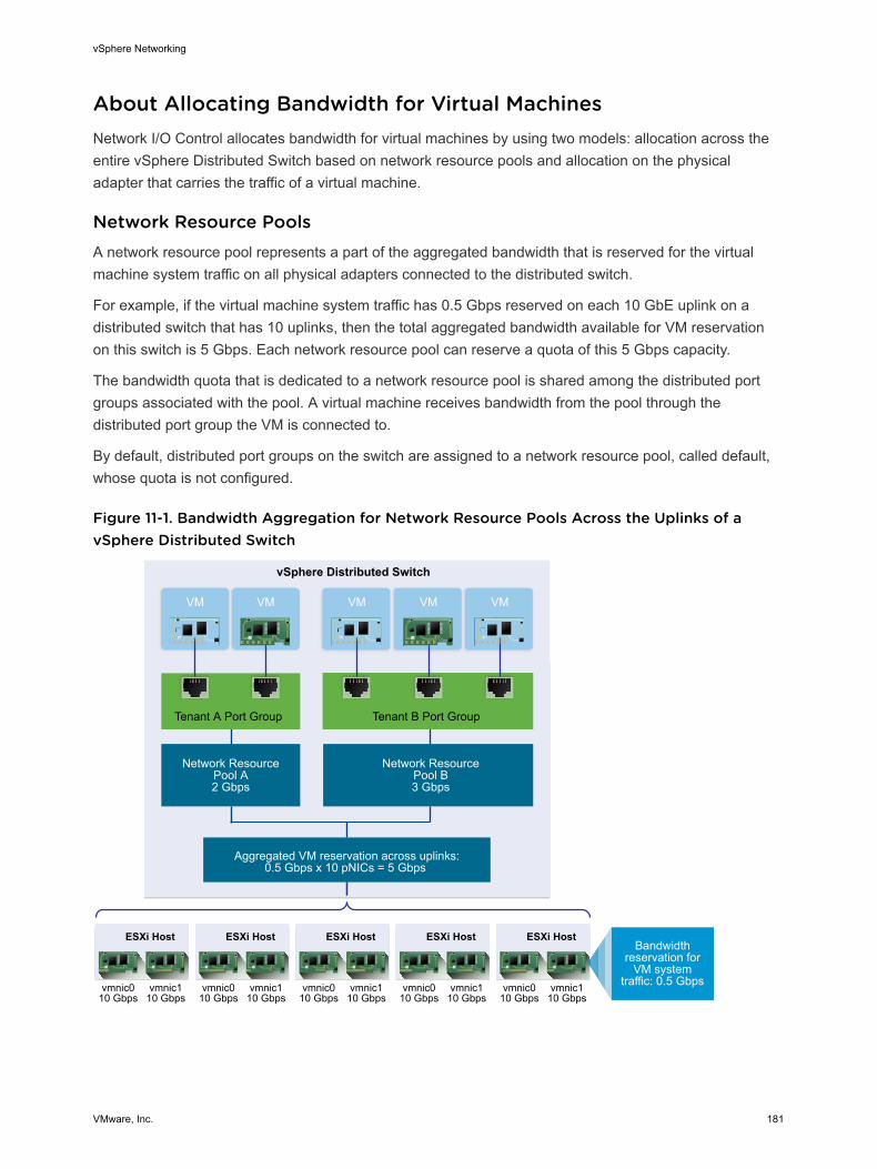
About Allocating Bandwidth for Virtual MachinesNetwork I/O Control allocates bandwidth for virtual machines by using two models: allocation across the entire vSphere Distributed Switch based on network resource pools and allocation on the physical adapter that carries the traffic of a virtual machine.
Network Resource PoolsA network resource pool represents a part of the aggregated bandwidth that is reserved for the virtual machine system traffic on all physical adapters connected to the distributed switch.
For example, if the virtual machine system traffic has 0.5 Gbps reserved on each 10 GbE uplink on a distributed switch that has 10 uplinks, then the total aggregated bandwidth available for VM reservation on this switch is 5 Gbps. Each network resource pool can reserve a quota of this 5 Gbps capacity.
The bandwidth quota that is dedicated to a network resource pool is shared among the distributed port groups associated with the pool. A virtual machine receives bandwidth from the pool through the distributed port group the VM is connected to.
By default, distributed port groups on the switch are assigned to a network resource pool, called default, whose quota is not configured.
Figure 11-1. Bandwidth Aggregation for Network Resource Pools Across the Uplinks of a vSphere Distributed Switch
Network ResourcePool A2 Gbps
Aggregated VM reservation across uplinks:0.5 Gbps x 10 pNICs = 5 Gbps
Network ResourcePool B3 Gbps
vSphere Distributed Switch
Bandwidthreservation for
VM systemtraffic: 0.5 Gbps
Tenant A Port Group
VMVM
Tenant B Port Group
VMVM VM
ESXi Host
vmnic010 Gbps
vmnic110 Gbps
ESXi Host
vmnic010 Gbps
vmnic110 Gbps
ESXi Host
vmnic010 Gbps
vmnic110 Gbps
ESXi Host
vmnic010 Gbps
vmnic110 Gbps
ESXi Host
vmnic010 Gbps
vmnic110 Gbps
vSphere Networking
VMware, Inc. 181

Defining Bandwidth Requirements for a Virtual MachineYou allocate bandwidth to an individual virtual machine similarly to allocating CPU and memory resources. Network I/O Control version 3 provisions bandwidth to a virtual machine according to shares, reservation, and limits that are defined for a network adapter in the VM hardware settings. The reservation represents a guarantee that the traffic from the virtual machine can consume at least the specified bandwidth. If a physical adapter has more capacity, the virtual machine may use additional bandwidth according to the specified shares and limit.
Bandwidth Provisioning to a Virtual Machine on the HostTo guarantee bandwidth, Network I/O Control implements a traffic placement engine that becomes active if a virtual machine has bandwidth reservation configured. The distributed switch attempts to place the traffic from a VM network adapter to the physical adapter that can supply the required bandwidth and is in the scope of the active teaming policy.
The total bandwidth reservation of the virtual machines on a host cannot exceed the reserved bandwidth that is configured for the virtual machine system traffic.
The actual limit and reservation also depends on the traffic shaping policy for the distributed port group the adapter is connected to. For example, if a VM network adapter requires a limit of 200 Mbps and the average bandwidth configured in the traffic shaping policy is 100 Mbps, then the effective limit becomes 100Mbps.
Figure 11-2. Configuration for Bandwidth Allocation for Individual Virtual Machines
Tenant APort Group
vmnic010 Gbps
Uplink Port Group
Bandwidth reservationfor VM system traffic:
0.5 Gbps
Tenant AVM
Tenant BVM
50 2 Gbps 0.2 Gbps
50 2 Gbps 0.3 Gbps
Tenant BPort Group
vSphere DistributedSwitch Total VM reservation:
Less than or equal tothe reservation forVM system traffic
Shares Limit ReservationTraffic
VM
ESXi Host
VM
vSphere Networking
VMware, Inc. 182
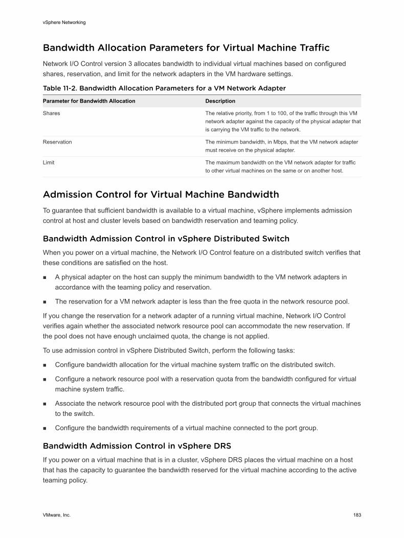
Bandwidth Allocation Parameters for Virtual Machine TrafficNetwork I/O Control version 3 allocates bandwidth to individual virtual machines based on configured shares, reservation, and limit for the network adapters in the VM hardware settings.
Table 11-2. Bandwidth Allocation Parameters for a VM Network Adapter
Parameter for Bandwidth Allocation Description
Shares The relative priority, from 1 to 100, of the traffic through this VM network adapter against the capacity of the physical adapter that is carrying the VM traffic to the network.
Reservation The minimum bandwidth, in Mbps, that the VM network adapter must receive on the physical adapter.
Limit The maximum bandwidth on the VM network adapter for traffic to other virtual machines on the same or on another host.
Admission Control for Virtual Machine BandwidthTo guarantee that sufficient bandwidth is available to a virtual machine, vSphere implements admission control at host and cluster levels based on bandwidth reservation and teaming policy.
Bandwidth Admission Control in vSphere Distributed SwitchWhen you power on a virtual machine, the Network I/O Control feature on a distributed switch verifies that these conditions are satisfied on the host.
n A physical adapter on the host can supply the minimum bandwidth to the VM network adapters in accordance with the teaming policy and reservation.
n The reservation for a VM network adapter is less than the free quota in the network resource pool.
If you change the reservation for a network adapter of a running virtual machine, Network I/O Control verifies again whether the associated network resource pool can accommodate the new reservation. If the pool does not have enough unclaimed quota, the change is not applied.
To use admission control in vSphere Distributed Switch, perform the following tasks:
n Configure bandwidth allocation for the virtual machine system traffic on the distributed switch.
n Configure a network resource pool with a reservation quota from the bandwidth configured for virtual machine system traffic.
n Associate the network resource pool with the distributed port group that connects the virtual machines to the switch.
n Configure the bandwidth requirements of a virtual machine connected to the port group.
Bandwidth Admission Control in vSphere DRSIf you power on a virtual machine that is in a cluster, vSphere DRS places the virtual machine on a host that has the capacity to guarantee the bandwidth reserved for the virtual machine according to the active teaming policy.
vSphere Networking
VMware, Inc. 183

vSphere DRS migrates a virtual machine to another host to satisfy the bandwidth reservation of the virtual machine in these situations:
n The reservation is changed to a value that the initial host can no longer satisfy.
n A physical adapter that carries traffic from the virtual machine is offline.
To use admission control in vSphere DRS, perform the following tasks:
n Configure bandwidth allocation for the virtual machine system traffic on the distributed switch.
n Configure the bandwidth requirements of a virtual machine that is connected to the distributed switch.
For more information about resource management according to bandwidth demands of virtual machines, see the vSphere Resource Management documentation.
Bandwidth Admission Control in vSphere HAWhen a host fails or is isolated, vSphere HA powers on a virtual machine on another host in the cluster according to the bandwidth reservation and teaming policy.
To use admission control in vSphere HA, perform the following tasks:
n Allocate bandwidth for the virtual machine system traffic.
n Configure the bandwidth requirements of a virtual machine that is connected to the distributed switch.
For more information about vSphere HA provides failover based on the bandwidth demands of virtual machines, see the vSphere Availability documentation.
Create a Network Resource PoolCreate network resource pools on a vSphere Distributed Switch to reserve bandwidth for a set of virtual machines.
A network resource pool provides a reservation quota to virtual machines. The quota represents a portion of the bandwidth that is reserved for virtual machine system traffic on the physical adapters connected to the distributed switch. You can set aside bandwidth from the quota for the virtual machines that are associated with the pool. The reservation from the network adapters of powered on VMs that are associated with the pool must not exceed the quota of the pool. See About Allocating Bandwidth for Virtual Machines.
Prerequisites
n Verify that vSphere Distributed Switch is version 6.0.0 and later.
n Verify that Network I/O Control on the switch is version 3.
n Verify that Network I/O Control is enabled. See Enable Network I/O Control on a vSphere Distributed Switch.
n Verify that the virtual machine system traffic has a configured bandwidth reservation. See Configure Bandwidth Allocation for System Traffic.
vSphere Networking
VMware, Inc. 184
Procedure
1 In the vSphere Web Client, navigate to the distributed switch.
2 On the Configure tab, expand Resource Allocation.
3 Click Network resource pools.
4 Click the Add icon.
5 (Optional) Type a name and a description for the network resource pool.
6 Enter a value for Reservation quota, in Mbps, from the free bandwidth that is reserved for the virtual machine system traffic.
The maximum quota that you can assign to the pool is determined according to the following formula:
max reservation quota = aggregated reservation for vm system traffic - quotas of the other
resource pools
where
n aggregated reservation for vm system traffic = configured bandwidth reservation for the virtual machine system traffic on each pNIC * number of pNICs connected to the distributed switch
n quotas of the other pools = the sum of the reservation quotas of the other network resource pools
7 Click OK.
What to do next
Add one or more distributed port groups to the network resource pool so that you can allocate bandwidth to individual virtual machines from the quota of the pool. See Add a Distributed Port Group to a Network Resource Pool.
Add a Distributed Port Group to a Network Resource PoolAdd a distributed port group to a network resource pool so that you can allocate bandwidth to the virtual machines that are connected to the port group.
To assign a network resource pool to several distributed port groups at once, you can use the Resource allocation policy in the Manage Distributed Port Groups wizard. See Manage Policies for Multiple Port Groups on a vSphere Distributed Switch.
Network I/O Control allocates bandwidth to the virtual machines associated with the distributed port group according to the model implemented in the Network I/O Control version that is active on the distributed switch. See About vSphere Network I/O Control Version 3.
Prerequisites
n Verify that Network I/O Control is enabled. See Enable Network I/O Control on a vSphere Distributed Switch.
vSphere Networking
VMware, Inc. 185
Procedure
1 Locate a distributed port group in the vSphere Web Client.
a Select a distributed switch and click the Networks tab.
b Click Distributed Port Groups.
2 Select the distributed port group and click Edit distributed port group settings.
3 In the Edit Settings dialog box, click General.
4 From the Network resource pool drop-down menu, select the network resource pool and click OK.
If the distributed switch does not contain network resource pools, you see only the (default) option in the drop-down menu.
Configure Bandwidth Allocation for a Virtual MachineYou can configure bandwidth allocation to individual virtual machines that are connected to a distributed port group. You can use shares, reservation, and limit settings for bandwidth.
Prerequisites
n Verify that vSphere Distributed Switch is version 6.0.0 and later.
n Verify that Network I/O Control on the switch is version 3.
n Verify that Network I/O Control is enabled. See Enable Network I/O Control on a vSphere Distributed Switch.
n Verify that the virtual machine system traffic has a configured bandwidth reservation. See Configure Bandwidth Allocation for System Traffic.
Procedure
1 Locate the virtual machine in the vSphere Web Client.
a Select a data center, folder, cluster, resource pool, or host and click the VMs tab.
b Click Virtual Machines and double-click the virtual machine from the list.
2 On the Configure tab of the virtual machine, expand Settings and select VM Hardware.
3 Click Edit.
4 Expand the Network adapter X section of the VM network adapter.
5 If you want to configure bandwidth allocation for a new VM network adapter, from the New device drop-down menu select Network and click Add.
A New Network section displays options for bandwidth allocation and other network adapter settings.
6 If the VM network adapter is not connected to the distributed port group, select the port group from the drop-down menu next to the Network adapter X or New Network label.
The Shares, Reservation, and Limit settings appear for the VM network adapter.
vSphere Networking
VMware, Inc. 186
7 From the Shares drop-down menu, set the relative priority of the traffic from this virtual machine as shares from the capacity of the connected physical adapter.
Network I/O Control applies the configured shares when a physical adapter is saturated.
You can select an option to set a pre-defined value, or select Custom and type a number from 1 to 100 to set another share.
8 In the Reservation text box, reserve a minimum bandwidth that must be available to the VM network adapter when the virtual machine is powered on.
If you provision bandwidth by using a network resource pool, the reservation from the network adapters of powered on VMs that are associated with the pool must not exceed the quota of the pool.
If vSphere DRS is enabled, to power on the virtual machine, make sure that the reservation from all VM network adapters on the host does not exceed the bandwidth reserved for virtual machine system traffic on the host physical adapters.
9 In the Limit text box, set a limit on the bandwidth that the VM network adapter can consume.
10 Click OK.
Results
Network
I/O Control allocates the bandwidth that you reserved for the network adapter of the virtual machine out of the reservation quota of the network resource pool.
Configure Bandwidth Allocation on Multiple Virtual MachinesWith a single operation, configure bandwidth allocation on multiple virtual machines that are connected to a specific network resource pool, for example, after you upgrade Network I/O Control to version 3.
Prerequisites
n Verify that vSphere Distributed Switch is version 6.0.0 and later.
n Verify that Network I/O Control on the switch is version 3.
n Verify that Network I/O Control is enabled. See Enable Network I/O Control on a vSphere Distributed Switch.
n Verify that the virtual machine system traffic has a configured bandwidth reservation. See Configure Bandwidth Allocation for System Traffic.
n Verify that the virtual machines are associated with a specific network resource pool through the connected distributed port groups. See Add a Distributed Port Group to a Network Resource Pool.
Procedure
1 In the vSphere Web Client, navigate to the distributed switch.
2 On the Configure tab, expand Resource Allocation.
3 Click Network resource pools.
vSphere Networking
VMware, Inc. 187
4 Select a network resource pool.
5 Click Virtual Machines.
A list of the VM network adapters that are connected to the selected network resource pool appears.
6 Select the VM network adapters whose settings you want to configure and click Edit.
7 From the Shares drop-down menu, set the relative priority of traffic from these virtual machines in the scope of the physical adapters that carry the traffic.
Network I/O Control applies the configured shares when a physical adapter is saturated.
8 In the Reservation text box, reserve a minimum bandwidth that must be available to each VM network adapter when the virtual machines are powered on.
If you provision bandwidth by using a network resource pool, the reservation from the network adapters of powered on VMs that are associated with the pool must not exceed the quota of the pool.
9 In the Limit text box, set a limit on the bandwidth that each VM network adapter can consume.
10 Click OK.
Change the Quota of a Network Resource PoolChange the quota of bandwidth that you can reserve for virtual machines connected to a set of distributed port groups.
Prerequisites
n Verify that vSphere Distributed Switch is version 6.0.0 and later.
n Verify that Network I/O Control on the switch is version 3.
n Verify that Network I/O Control is enabled. See Enable Network I/O Control on a vSphere Distributed Switch.
n Verify that the virtual machine system traffic has a configured bandwidth reservation. See Configure Bandwidth Allocation for System Traffic.
Procedure
1 In the vSphere Web Client, navigate to the distributed switch.
2 On the Configure tab, expand Resource Allocation.
3 Click Network resource pools.
4 Select a network resource pool from the list and click Edit.
5 In the Reservation quota text box, enter the bandwidth quota for virtual machines from the aggregation of free bandwidth that is reserved for virtual machine system traffic on all physical adapters on the switch.
6 Click OK.
vSphere Networking
VMware, Inc. 188
Remove a Distributed Port Group from a Network Resource PoolTo stop allocating bandwidth to the virtual machines from the reservation quota of a network resource pool, remove the association between the port group to which the virtual machines are connected and the pool.
Procedure
1 Locate a distributed port group in the vSphere Web Client.
a Select a distributed switch and click the Networks tab.
b Click Distributed Port Groups.
2 Select the distributed port group and click Edit distributed port group settings.
3 In the Edit Settings dialog box for the port group, click General.
4 From the Network resource pool drop-down menu, select (default) and click OK.
Results
The distributed port group becomes associated with the default VM network resource pool.
Delete a Network Resource PoolDelete a network resource pool that is no longer in use.
Prerequisites
Uncouple the network resource pool from all associated distributed port groups. See Remove a Distributed Port Group from a Network Resource Pool.
Procedure
1 In the vSphere Web Client, navigate to the distributed switch.
2 On the Configure tab, expand Resource Allocation.
3 Click Network resource pools.
4 Select a network resource pool and click Remove.
5 Click Yes to delete the resource pool.
Move a Physical Adapter Out the Scope of Network I/O ControlUnder certain conditions you might need to exclude physical adapters with low capacity from the bandwidth allocation model of Network I/O Control version 3.
For example, if the bandwidth allocation on a vSphere Distributed Switch is tailored on top of 10 GbE NICs, you might not be able to add a 1GbE NIC to the switch because it cannot meet the higher allocation requirements configured on the 10GbE NICs.
vSphere Networking
VMware, Inc. 189
Prerequisites
n Verify that the host is running ESXi 6.0 and later.
n Verify that vSphere Distributed Switch is version 6.0.0 and later.
n Verify that Network I/O Control on the switch is version 3.
Procedure
1 In the vSphere Web Client, navigate to the host.
2 On the Configure tab, expand System and select Advanced System Settings .
3 Set the physical adapters that you need to function outside the scope of Network I/O Control as a comma-separated list to the Net.IOControlPnicOptOut parameter.
For example: vmnic0,vmnic3
4 Click OK to apply the changes.
vSphere Networking
VMware, Inc. 190

MAC Address Management 12MAC addresses are used in the Layer 2 (Data Link Layer) of the network protocol stack to transmit frames to a recipient. In vSphere, vCenter Server generates MAC addresses for virtual machine adapters and VMkernel adapters, or you can assign addresses manually.
Each network adapter manufacturer is assigned a unique three-byte prefix called an Organizationally Unique Identifier (OUI), which it can use to generate unique MAC addresses.
VMware supports several address allocation mechanisms, each of them with a separate OUI:
n Generated MAC addresses
n Assigned by vCenter Server
n Assigned by the ESXi host
n Manually set MAC addresses
n Generated for legacy virtual machines, but no longer used with ESXi
If you reconfigure the network adapter of a powered off virtual machine, for example by changing the automatic MAC address allocation type, or setting a static MAC address, vCenter Server resolves any MAC address conflict before the adapter reconfiguration takes effect.
This chapter includes the following topics:
n MAC Address Assignment from vCenter Server
n MAC Address Generation on ESXi Hosts
n Setting a Static MAC Address to a Virtual Machine
MAC Address Assignment from vCenter ServervSphere provides several schemes for automatic allocation of MAC addresses in vCenter Server. You can select the scheme that best suits your requirements for MAC address duplication, OUI requirements for locally administered or universally administered addresses, and so on.
The following schemes of MAC address generation are available in vCenter Server:
n VMware OUI allocation, default allocation
n Prefix-based allocation
VMware, Inc. 191
n Range-based allocation
After the MAC address is generated, it does not change unless the virtual machine's MAC address conflicts with that of another registered virtual machine. The MAC address is saved in the configuration file of the virtual machine.
Note If you use invalid prefix- or range-based allocation values, an error is logged in the vpxd.log file. vCenter Server does not allocate MAC addresses when provisioning a virtual machine.
Preventing MAC Address ConflictsThe MAC address of a powered off virtual machine is not checked against the addresses of running or suspended virtual machines.
When a virtual machine is powered on again, it might acquire a different MAC address. The change might be caused by an address conflict with another virtual machine. While this virtual machine has been powered off, its MAC address has been assigned to another virtual machine that has been powered on.
If you reconfigure the network adapter of a powered off virtual machine, for example, by changing the automatic MAC address allocation type or setting a static MAC address, vCenter Server resolves MAC address conflicts before the adapter reconfiguration takes effect.
For information about resolving MAC address conflicts, see the vSphere Troubleshooting documentation.
VMware OUI AllocationVMware Organizationally Unique Identifier (OUI) allocation assigns MAC addresses based on the default VMware OUI 00:50:56 and the vCenter Server ID.
VMware OUI allocation is the default MAC address assignment model for virtual machines. The allocation works with up to 64 vCenter Server instances, and each vCenter Server can assign up to 64000 unique MAC addresses. The VMware OUI allocation scheme is suitable for small scale deployments.
MAC Address FormatAccording to the VMware OUI allocation scheme, a MAC address has the format 00:50:56:XX:YY:ZZ where 00:50:56 represents the VMware OUI, XX is calculated as (80 + vCenter Server ID), and YY and ZZ are random two-digit hexadecimal numbers.
The addresses created through the VMware OUI allocation are in the range 00:50:56:80:YY:ZZ - 00:50:56:BF:YY:ZZ.
Prefix-Based MAC Address AllocationYou can use prefix-based allocation to specify an OUI other than the default one 00:50:56 by VMware, or to introduce Locally Administered MAC Addresses (LAA) for a larger address space.
Prefix-based MAC address allocation overcomes the limits of the default VMware allocation to provide unique addresses in larger scale deployments. Introducing an LAA prefix leads to a very large MAC address space (2 to the power of 46) instead of an universally unique address OUI which can give only 16 million MAC addresses.
vSphere Networking
VMware, Inc. 192
Verify that the prefixes that you provide for different vCenter Server instances in the same network are unique. vCenter Server relies on the prefixes to avoid MAC address duplication issues. See the vSphere Troubleshooting documentation.
Range-Based MAC Address AllocationYou can use range-based allocation to include or exclude ranges of Locally Administered Addresses (LAA).
You specify one or more ranges using a starting and ending MAC addresses, for example,(02:50:68:00:00:02, 02:50:68:00:00:FF). MAC addresses are generated only from within the specified range.
You can specify multiple ranges of LAA, and vCenter Server tracks the number of used addresses for each range. vCenter Server allocates MAC addresses from the first range that still has addresses available. vCenter Server checks for MAC address conflicts within its ranges.
When using range-based allocation, you must provide different instances of vCenter Server with ranges that do not overlap. vCenter Server does not detect ranges that might be in conflict with other vCenter Server instances. See the vSphere Troubleshooting documentation for more information about resolving issues with duplicate MAC addresses.
Assigning a MAC AddressUse the vSphere Web Client to enable prefix-based or range-based MAC address allocation and to adjust the allocation parameters.
If you are changing from one type of allocation to another, for example changing from the VMware OUI allocation to a range-based allocation, use the vSphere Web Client. However, when a schema is prefix-based or range-based and you want to change to a different allocation schema, you must edit the vpxd.cfd file manually and restart vCenter Server.
Change to or Adjust Range- or Prefixed-Based AllocationsBy switching from the default VMware OUI to range- or prefixed-based MAC address allocation through the vSphere Web Client, you can avoid and resolve MAC address duplication conflicts in vSphere deployments.
Change the allocation scheme from the default VMware OUI to range- or to prefixed-based allocation by using the Advanced Settings available for the vCenter Server instance in the vSphere Web Client.
To switch from range- or prefixed-based allocation back to VMware OUI allocation, or between range- and prefixed-based allocation, edit the vpxd.cfg file manually. See Set or Change Allocation Type.
Procedure
1 In the vSphere Web Client, navigate to a vCenter Server instance.
2 On the Configure tab, expand Settings and select Advanced Settings.
3 Click Edit.
vSphere Networking
VMware, Inc. 193
4 Add or edit parameters for the target allocation type.
Use only one allocation type.
n Change to prefix-based allocation.
Key Example Value
config.vpxd.macAllocScheme.prefixScheme.prefix 005026
config.vpxd.macAllocScheme.prefixScheme.prefixLength 23
prefix and prefixLength determine the range of MAC address prefixes that newly added vNICs have. prefix is the starting OUI of MAC addresses related to the vCenter Server instance, and prefixLength determines the length of the prefix in bits.
For example, the settings from the table result in VM NIC MAC addresses starting with 00:50:26 or 00:50:27.
n Change to range-based allocation.
Key Example Value
config.vpxd.macAllocScheme.rangeScheme.range[X].begin 005067000000
config.vpxd.macAllocScheme.rangeScheme.range[X].end 005067ffffff
X in range[X] stands for the range sequence number. For example, 0 in range[0] represents the allocation settings of the first range for MAC address allocation.
5 Click OK.
Set or Change Allocation TypeIf you are changing from range- or prefixed-based allocation to the VMware OUI allocation, you must set the allocation type in the vpxd.cfd file and restart the vCenter Server.
Prerequisites
Decide on an allocation type before changing the vpxd.cfg file. For information on allocation types, see MAC Address Assignment from vCenter Server
Procedure
1 On the host machine of vCenter Server, navigate to the directory that contains the configuration file:
n On a Windows Server operating system, the location of the directory is C:\ProgramData\VMware\CIS\cfg\vmware-vpx.
n On the vCenter Server Appliance, the location of the directory is /etc/vmware-vpx.
2 Open the vpxd.cfg file.
vSphere Networking
VMware, Inc. 194
3 Decide on an allocation type to use and enter the corresponding XML code in the file to configure the allocation type.
The following are examples of XML code to use.
Note Use only one allocation type.
u VMware OUI allocation
<vpxd>
<macAllocScheme>
<VMwareOUI>true</VMwareOUI>
</macAllocScheme>
</vpxd>
u Prefix-based allocation
<vpxd>
<macAllocScheme>
<prefixScheme>
<prefix>005026</prefix>
<prefixLength>23</prefixLength>
</prefixScheme>
</macAllocScheme>
</vpxd>
u Range-based allocation
<vpxd>
<macAllocScheme>
<rangeScheme>
<range id="0">
<begin>005067000001</begin>
<end>005067000001</end>
</range>
</rangeScheme>
</macAllocScheme>
</vpxd>
4 Save the vpxd.cfg.
5 Restart the vCenter Server host.
MAC Address Generation on ESXi HostsAn ESXi host generates the MAC address for a virtual machine adapter when the host is not connected to vCenter Server. Such addresses have a separate VMware OUI to avoid conflicts.
The ESXi host generates the MAC address for a virtual machine adapter in one of the following cases:
n The host is not connected to vCenter Server.
n The virtual machine configuration file does not contain the MAC address and information about the MAC address allocation type.
vSphere Networking
VMware, Inc. 195
MAC Address FormatThe host generates MAC addresses that consists of the VMware OUI 00:0C:29 and the last three octets in hexadecimal format of the virtual machine UUID. The virtual machine UUID is based on a hash calculated by using the UUID of the ESXi physical machine and the path to the configuration file (.vmx) of the virtual machine.
Preventing MAC Address ConflictsAll MAC addresses that have been assigned to network adapters of running and suspended virtual machines on a given physical machine are tracked for conflicts.
If you import a virtual machine with a host-generated MAC address from one vCenter Server to another, select the I Copied It option when you power on the virtual machine to regenerate the address and avoid potential conflicts in the target vCenter Server or between the vCenter Server systems.
Setting a Static MAC Address to a Virtual MachineIn most network deployments, generated MAC addresses are a good approach. However, you might need to set a static MAC address for a virtual machine adapter with unique value.
The following cases show when you might set a static MAC address:
n Virtual machine adapters on different physical hosts share the same subnet and are assigned the same MAC address, causing a conflict.
n Ensure that a virtual machine adapter always has the same MAC address.
By default, VMware uses the Organizationally Unique Identifier (OUI) 00:50:56 for manually generated addresses, but all unique manually generated addresses are supported.
Note Make sure that no other non-VMware devices use addresses assigned to VMware components. For example, you might have physical servers in the same subnet, which use 11:11:11:11:11:11, 22:22:22:22:22:22 as static MAC addresses. The physical servers do not belong to the vCenter Server inventory, and vCenter Server is not able to check for address collision.
VMware OUI in Static MAC AddressesBy default, static MAC addresses have the VMware Organizationally Unique Identifier (OUI) as the prefix. However, the range of free address provided by the VMware OUI is restricted.
If you decide to use the VMware OUI, part of the range is reserved for use by vCenter Server, host physical NICs, virtual NICs, and for future use.
You can set a static MAC address that contains the VMware OUI prefix in compliance with the following format:
00:50:56:XX:YY:ZZ
vSphere Networking
VMware, Inc. 196
where XX is a valid hexadecimal number between 00 and 3F, and YY and ZZ are valid hexadecimal numbers between 00 and FF. To avoid conflict with MAC addresses that are generated by vCenter Server or are assigned to VMkernel adapters for infrastructure traffic, the value for XX must not be greater than 3F.
The maximum value for a manually generated MAC address is as follows.
00:50:56:3F:FF:FF
To avoid conflicts between the generated MAC addresses and the manually assigned ones, select a unique value for XX:YY:ZZ from your hard-coded addresses.
Assign a Static MAC Address by Using the vSphere Web ClientYou can assign static MAC addresses to the virtual NIC of a powered off virtual machine by using the vSphere Web Client.
Procedure
1 Locate the virtual machine in the vSphere Web Client.
a Select a data center, folder, cluster, resource pool, or host and click the VMs tab.
b Click Virtual Machines and double-click the virtual machine from the list.
2 Power off the virtual machine.
3 On the Configure tab of the virtual machine, expand Settings and select VM Hardware.
4 Click Edit and select the Virtual Hardware tab in the dialog box displaying the settings.
5 In the Virtual Hardware tab, expand the network adapter section.
6 Under MAC Address, select Manual from the drop-down menu.
7 Type the static MAC address, and click OK.
8 Power on the virtual machine.
Assign a Static MAC Address in the Virtual Machine Configuration FileTo set a static MAC address for a virtual machine, you can edit the configuration file of the virtual machine by using the vSphere Web Client.
Procedure
1 Locate the virtual machine in the vSphere Web Client.
a Select a data center, folder, cluster, resource pool, or host and click the VMs tab.
b Click Virtual Machines and double-click the virtual machine from the list.
2 Power off the virtual machine.
3 On the Configure tab of the virtual machine, expand Settings and select VM Options.
vSphere Networking
VMware, Inc. 197
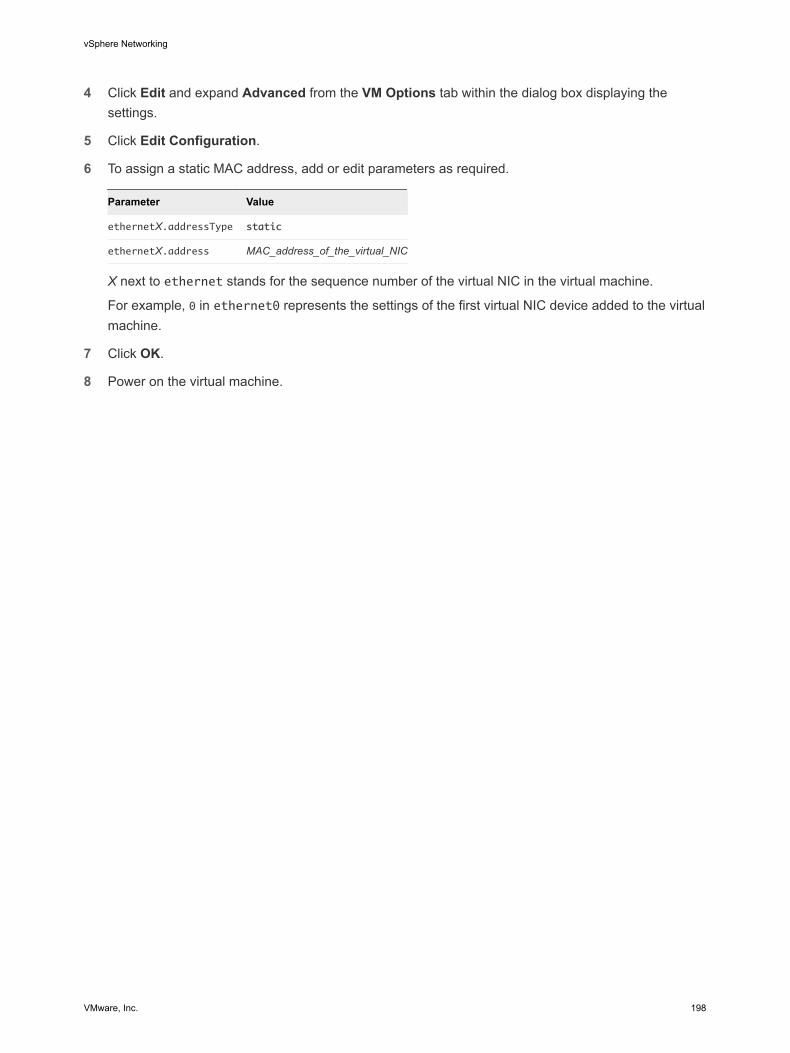
4 Click Edit and expand Advanced from the VM Options tab within the dialog box displaying the settings.
5 Click Edit Configuration.
6 To assign a static MAC address, add or edit parameters as required.
Parameter Value
ethernetX.addressType static
ethernetX.address MAC_address_of_the_virtual_NIC
X next to ethernet stands for the sequence number of the virtual NIC in the virtual machine.
For example, 0 in ethernet0 represents the settings of the first virtual NIC device added to the virtual machine.
7 Click OK.
8 Power on the virtual machine.
vSphere Networking
VMware, Inc. 198
Configuring vSphere for IPv6 13Configure ESXi hosts and vCenter Server for operation in a pure IPv6 environment for larger address space and improved address assignment.
IPv6 is designated by the Internet Engineering Task Force (IETF) as the successor to IPv4 providing the following benefits:
n Increased address length. The increased address space resolves the problem of address exhaustion and eliminates the need for network address translation. IPv6 uses 128-bit addresses compared with the 32-bit addresses used by IPv4.
n Ability for improved address autoconfiguration of nodes.
This chapter includes the following topics:
n vSphere IPv6 Connectivity
n Deploying vSphere on IPv6
n Enable or Disable IPv6 Support on a Host
n Set Up IPv6 on an ESXi Host
n Setting Up IPv6 on vCenter Server
vSphere IPv6 ConnectivityIn an environment that is based on vSphere 6.0 and later, nodes and features can communicate over IPv6 transparently supporting static and automatic address configuration.
IPv6 in the Communication between vSphere NodesThe nodes in a vSphere deployment can communicate using IPv6 and accept assigned addresses according to the network configuration.
VMware, Inc. 199
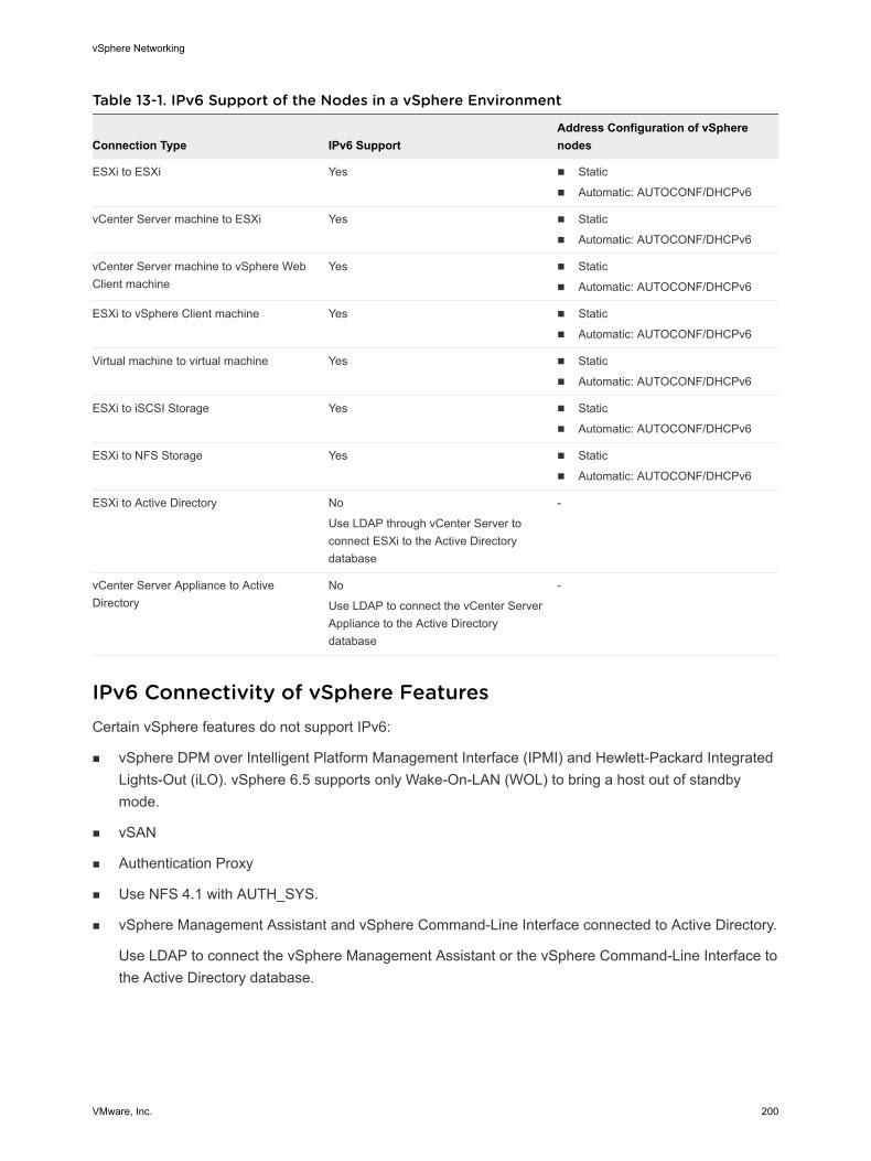
Table 13-1. IPv6 Support of the Nodes in a vSphere Environment
Connection Type IPv6 SupportAddress Configuration of vSphere nodes
ESXi to ESXi Yes n Static
n Automatic: AUTOCONF/DHCPv6
vCenter Server machine to ESXi Yes n Static
n Automatic: AUTOCONF/DHCPv6
vCenter Server machine to vSphere Web Client machine
Yes n Static
n Automatic: AUTOCONF/DHCPv6
ESXi to vSphere Client machine Yes n Static
n Automatic: AUTOCONF/DHCPv6
Virtual machine to virtual machine Yes n Static
n Automatic: AUTOCONF/DHCPv6
ESXi to iSCSI Storage Yes n Static
n Automatic: AUTOCONF/DHCPv6
ESXi to NFS Storage Yes n Static
n Automatic: AUTOCONF/DHCPv6
ESXi to Active Directory No
Use LDAP through vCenter Server to connect ESXi to the Active Directory database
-
vCenter Server Appliance to Active Directory
No
Use LDAP to connect the vCenter Server Appliance to the Active Directory database
-
IPv6 Connectivity of vSphere FeaturesCertain vSphere features do not support IPv6:
n vSphere DPM over Intelligent Platform Management Interface (IPMI) and Hewlett-Packard Integrated Lights-Out (iLO). vSphere 6.5 supports only Wake-On-LAN (WOL) to bring a host out of standby mode.
n vSAN
n Authentication Proxy
n Use NFS 4.1 with AUTH_SYS.
n vSphere Management Assistant and vSphere Command-Line Interface connected to Active Directory.
Use LDAP to connect the vSphere Management Assistant or the vSphere Command-Line Interface to the Active Directory database.
vSphere Networking
VMware, Inc. 200

IPv6 Connectivity of Virtual MachinesVirtual machines can exchange data in the network over IPv6. vSphere supports both static and automatic assignment of IPv6 addresses for virtual machines.
Configuring one or more IPv6 addresses is also possible when you customize the guest operating system of a virtual machine.
FQDNs and IPv6 AddressesIn vSphere, you should use fully qualified domain names (FQDNs) that are mapped to IPv6 addresses on the DNS server. You can use IPv6 addresses if they have a valid FQDN on the DNS server for reverse lookup.
To deploy vCenter Server in a pure IPv6 environment, you must use FQDNs only.
Deploying vSphere on IPv6Run vSphere in a pure IPv6 environment to use an extended address space and flexible address assignment.
If you plan to deploy vCenter Server and ESXi hosts in an IPv6 network, you must perform additional steps.
n Enable IPv6 on a vSphere Installation
If you have a greenfield deployment of vSphere 6.5 in an IPv6 network, configure ESXi and vCenter Server for pure IPv6 management connection by configuring IPv6 on the deployment nodes and connecting them.
n Enable IPv6 on an Upgraded vSphere Environment
On an IPv4 deployment of vSphere 6.5 that consists of an installed or upgraded vCenter Server and upgraded ESXi, configure ESXi and vCenter Server for pure IPv6 management connection by enabling IPv6 on the deployed nodes and reconnecting them.
Enable IPv6 on a vSphere InstallationIf you have a greenfield deployment of vSphere 6.5 in an IPv6 network, configure ESXi and vCenter Server for pure IPv6 management connection by configuring IPv6 on the deployment nodes and connecting them.
Prerequisites
n Verify that the IPv6 addresses for vCenter Server, the ESXi hosts and an external database, if used, are mapped to fully qualified domain names (FQDNs) on the DNS server.
n Verify that the network infrastructure provides IPv6 connectivity for the ESXi hosts, vCenter Server and external database if used.
n Verify that you have version 6.5 of vCenter Server installed with FQDN that is mapped to an IPv6 address. See the vCenter Server Installation and Setup documentation.
vSphere Networking
VMware, Inc. 201
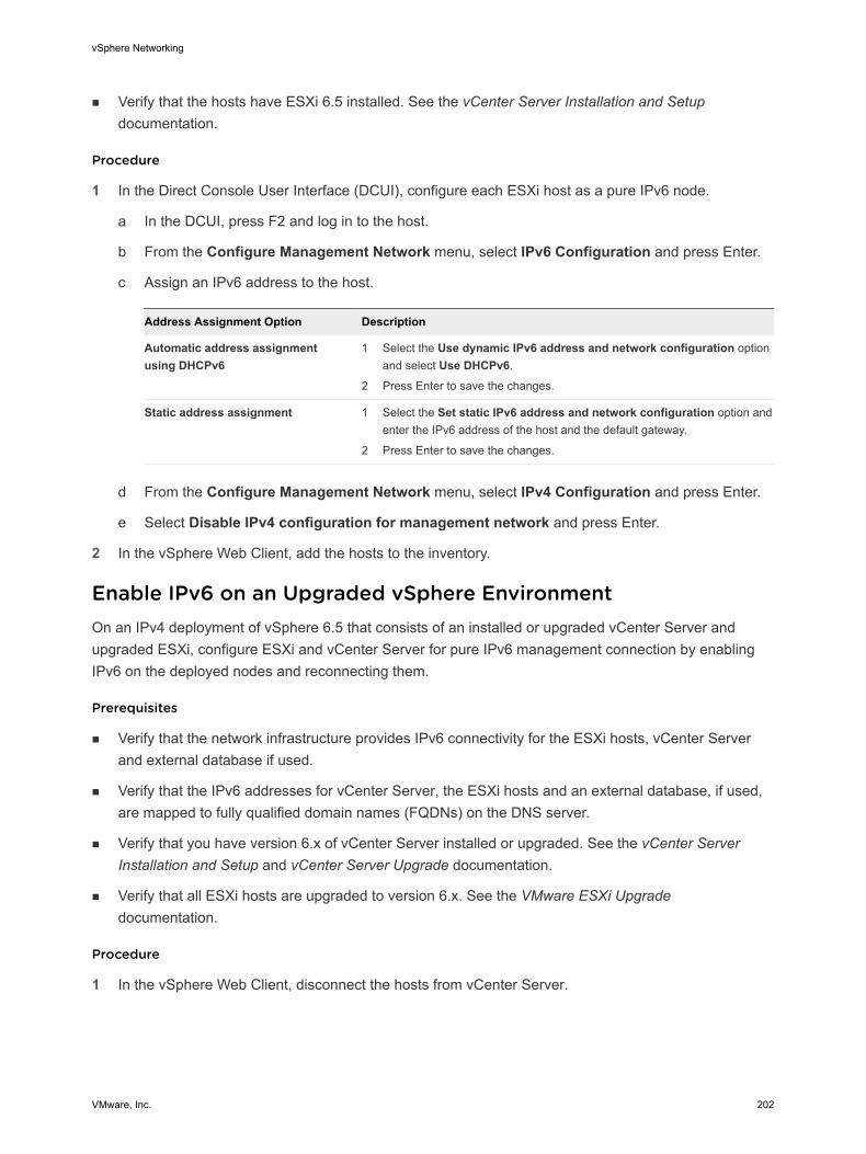
n Verify that the hosts have ESXi 6.5 installed. See the vCenter Server Installation and Setup documentation.
Procedure
1 In the Direct Console User Interface (DCUI), configure each ESXi host as a pure IPv6 node.
a In the DCUI, press F2 and log in to the host.
b From the Configure Management Network menu, select IPv6 Configuration and press Enter.
c Assign an IPv6 address to the host.
Address Assignment Option Description
Automatic address assignment using DHCPv6
1 Select the Use dynamic IPv6 address and network configuration option and select Use DHCPv6.
2 Press Enter to save the changes.
Static address assignment 1 Select the Set static IPv6 address and network configuration option and enter the IPv6 address of the host and the default gateway.
2 Press Enter to save the changes.
d From the Configure Management Network menu, select IPv4 Configuration and press Enter.
e Select Disable IPv4 configuration for management network and press Enter.
2 In the vSphere Web Client, add the hosts to the inventory.
Enable IPv6 on an Upgraded vSphere EnvironmentOn an IPv4 deployment of vSphere 6.5 that consists of an installed or upgraded vCenter Server and upgraded ESXi, configure ESXi and vCenter Server for pure IPv6 management connection by enabling IPv6 on the deployed nodes and reconnecting them.
Prerequisites
n Verify that the network infrastructure provides IPv6 connectivity for the ESXi hosts, vCenter Server and external database if used.
n Verify that the IPv6 addresses for vCenter Server, the ESXi hosts and an external database, if used, are mapped to fully qualified domain names (FQDNs) on the DNS server.
n Verify that you have version 6.x of vCenter Server installed or upgraded. See the vCenter Server Installation and Setup and vCenter Server Upgrade documentation.
n Verify that all ESXi hosts are upgraded to version 6.x. See the VMware ESXi Upgrade documentation.
Procedure
1 In the vSphere Web Client, disconnect the hosts from vCenter Server.
vSphere Networking
VMware, Inc. 202
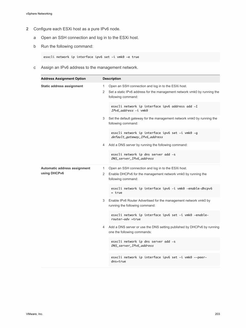
2 Configure each ESXi host as a pure IPv6 node.
a Open an SSH connection and log in to the ESXi host.
b Run the following command:
esxcli network ip interface ipv6 set -i vmk0 -e true
c Assign an IPv6 address to the management network.
Address Assignment Option Description
Static address assignment 1 Open an SSH connection and log in to the ESXi host.
2 Set a static IPv6 address for the management network vmk0 by running the following command:
esxcli network ip interface ipv6 address add -I IPv6_address -i vmk0
3 Set the default gateway for the management network vmk0 by running the following command:
esxcli network ip interface ipv6 set -i vmk0 -g default_gateway_IPv6_address
4 Add a DNS server by running the following command:
esxcli network ip dns server add -s DNS_server_IPv6_address
Automatic address assignment using DHCPv6
1 Open an SSH connection and log in to the ESXi host.
2 Enable DHCPv6 for the management network vmk0 by running the following command:
esxcli network ip interface ipv6 -i vmk0 -enable-dhcpv6 = true
3 Enable IPv6 Router Advertised for the management network vmk0 by running the following command:
esxcli network ip interface ipv6 set -i vmk0 -enable-router-adv =true
4 Add a DNS server or use the DNS setting published by DHCPv6 by running one the following commands:
esxcli network ip dns server add -s DNS_server_IPv6_address
esxcli network ip interface ipv6 set -i vmk0 --peer-dns=true
vSphere Networking
VMware, Inc. 203
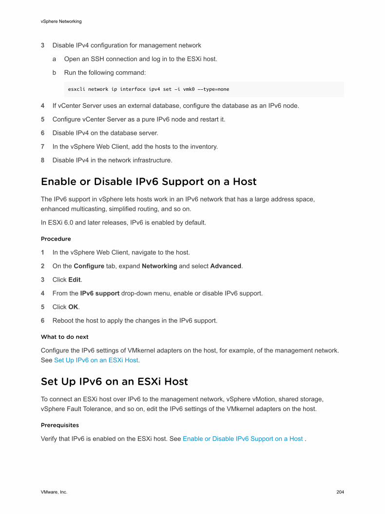
3 Disable IPv4 configuration for management network
a Open an SSH connection and log in to the ESXi host.
b Run the following command:
esxcli network ip interface ipv4 set -i vmk0 --type=none
4 If vCenter Server uses an external database, configure the database as an IPv6 node.
5 Configure vCenter Server as a pure IPv6 node and restart it.
6 Disable IPv4 on the database server.
7 In the vSphere Web Client, add the hosts to the inventory.
8 Disable IPv4 in the network infrastructure.
Enable or Disable IPv6 Support on a HostThe IPv6 support in vSphere lets hosts work in an IPv6 network that has a large address space, enhanced multicasting, simplified routing, and so on.
In ESXi 6.0 and later releases, IPv6 is enabled by default.
Procedure
1 In the vSphere Web Client, navigate to the host.
2 On the Configure tab, expand Networking and select Advanced.
3 Click Edit.
4 From the IPv6 support drop-down menu, enable or disable IPv6 support.
5 Click OK.
6 Reboot the host to apply the changes in the IPv6 support.
What to do next
Configure the IPv6 settings of VMkernel adapters on the host, for example, of the management network. See Set Up IPv6 on an ESXi Host.
Set Up IPv6 on an ESXi HostTo connect an ESXi host over IPv6 to the management network, vSphere vMotion, shared storage, vSphere Fault Tolerance, and so on, edit the IPv6 settings of the VMkernel adapters on the host.
Prerequisites
Verify that IPv6 is enabled on the ESXi host. See Enable or Disable IPv6 Support on a Host .
vSphere Networking
VMware, Inc. 204
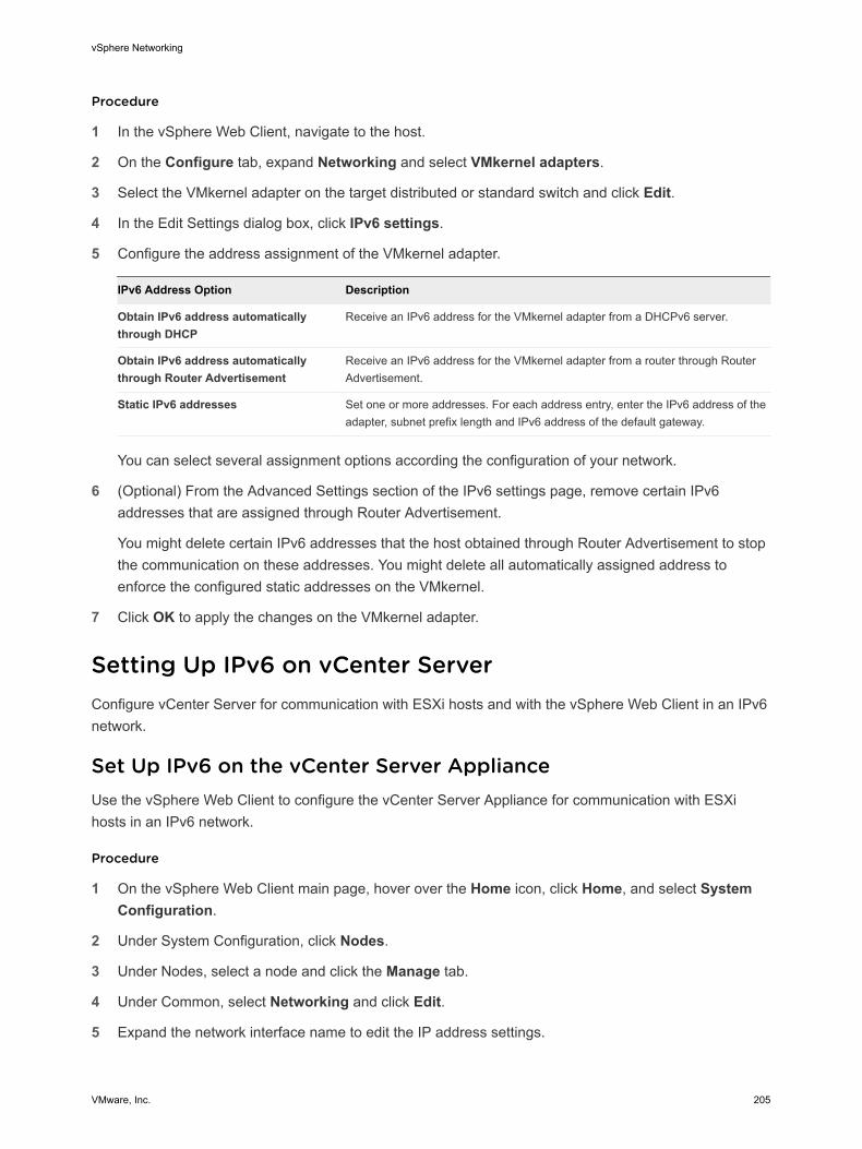
Procedure
1 In the vSphere Web Client, navigate to the host.
2 On the Configure tab, expand Networking and select VMkernel adapters.
3 Select the VMkernel adapter on the target distributed or standard switch and click Edit.
4 In the Edit Settings dialog box, click IPv6 settings.
5 Configure the address assignment of the VMkernel adapter.
IPv6 Address Option Description
Obtain IPv6 address automatically through DHCP
Receive an IPv6 address for the VMkernel adapter from a DHCPv6 server.
Obtain IPv6 address automatically through Router Advertisement
Receive an IPv6 address for the VMkernel adapter from a router through Router Advertisement.
Static IPv6 addresses Set one or more addresses. For each address entry, enter the IPv6 address of the adapter, subnet prefix length and IPv6 address of the default gateway.
You can select several assignment options according the configuration of your network.
6 (Optional) From the Advanced Settings section of the IPv6 settings page, remove certain IPv6 addresses that are assigned through Router Advertisement.
You might delete certain IPv6 addresses that the host obtained through Router Advertisement to stop the communication on these addresses. You might delete all automatically assigned address to enforce the configured static addresses on the VMkernel.
7 Click OK to apply the changes on the VMkernel adapter.
Setting Up IPv6 on vCenter ServerConfigure vCenter Server for communication with ESXi hosts and with the vSphere Web Client in an IPv6 network.
Set Up IPv6 on the vCenter Server ApplianceUse the vSphere Web Client to configure the vCenter Server Appliance for communication with ESXi hosts in an IPv6 network.
Procedure
1 On the vSphere Web Client main page, hover over the Home icon, click Home, and select System Configuration.
2 Under System Configuration, click Nodes.
3 Under Nodes, select a node and click the Manage tab.
4 Under Common, select Networking and click Edit.
5 Expand the network interface name to edit the IP address settings.
vSphere Networking
VMware, Inc. 205
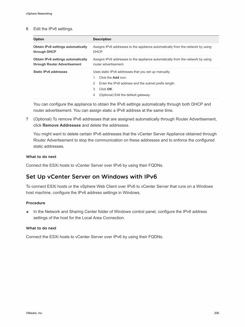
6 Edit the IPv6 settings.
Option Description
Obtain IPv6 settings automatically through DHCP
Assigns IPv6 addresses to the appliance automatically from the network by using DHCP.
Obtain IPv6 settings automatically through Router Advertisement
Assigns IPv6 addresses to the appliance automatically from the network by using router advertisement.
Static IPv6 addresses Uses static IPv6 addresses that you set up manually.
1 Click the Add icon.
2 Enter the IPv6 address and the subnet prefix length.
3 Click OK.
4 (Optional) Edit the default gateway.
You can configure the appliance to obtain the IPv6 settings automatically through both DHCP and router advertisement. You can assign static a IPv6 address at the same time.
7 (Optional) To remove IPv6 addresses that are assigned automatically through Router Advertisement, click Remove Addresses and delete the addresses.
You might want to delete certain IPv6 addresses that the vCenter Server Appliance obtained through Router Advertisement to stop the communication on these addresses and to enforce the configured static addresses.
What to do next
Connect the ESXi hosts to vCenter Server over IPv6 by using their FQDNs.
Set Up vCenter Server on Windows with IPv6To connect ESXi hosts or the vSphere Web Client over IPv6 to vCenter Server that runs on a Windows host machine, configure the IPv6 address settings in Windows.
Procedure
u In the Network and Sharing Center folder of Windows control panel, configure the IPv6 address settings of the host for the Local Area Connection.
What to do next
Connect the ESXi hosts to vCenter Server over IPv6 by using their FQDNs.
vSphere Networking
VMware, Inc. 206
Monitoring Network Connection and Traffic 14Monitor network connection and packets that pass through the ports of a vSphere Standard Switch or a vSphere Distributed Switch to analyze the traffic between virtual machines and hosts.
This chapter includes the following topics:
n Capture Network Packets by Using the PacketCapture Utility
n Capturing and Tracing Network Packets by Using the pktcap-uw Utility
n Configure the NetFlow Settings of a vSphere Distributed Switch
n Working With Port Mirroring
n vSphere Distributed Switch Health Check
n Switch Discovery Protocol
n View the Topology Diagram of an NSX Virtual Distributed Switch
Capture Network Packets by Using the PacketCapture UtilityUse the PacketCapture utility to diagnose networking problems such as slow connection, lost packets, and connectivity problems
PacketCapture is a lightweight tcpdump utility that captures and stores only the minimum amount of data that is needed to diagnose the network problem. PacketCapture is integrated in the rhttpproxy service of ESXi and vCenter Server Appliance. You start and stop PacketCapture by editing the rhttpproxy service XML configuration file.
VMware, Inc. 207
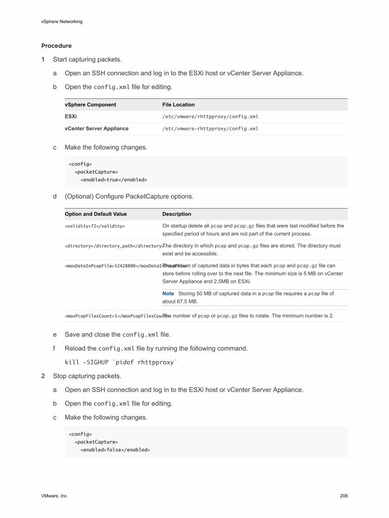
Procedure
1 Start capturing packets.
a Open an SSH connection and log in to the ESXi host or vCenter Server Appliance.
b Open the config.xml file for editing.
vSphere Component File Location
ESXi /etc/vmware/rhttpproxy/config.xml
vCenter Server Appliance /etc/vmware-rhttpproxy/config.xml
c Make the following changes.
<config>
<packetCapture>
<enabled>true</enabled>
d (Optional) Configure PacketCapture options.
Option and Default Value Description
<validity>72</validity> On startup delete all pcap and pcap.gz files that were last modified before the specified period of hours and are not part of the current process.
<directory>/directory_path</directory>The directory in which pcap and pcap.gz files are stored. The directory must exist and be accessible.
<maxDataInPcapFile>52428800</maxDataInPcapFile>The amount of captured data in bytes that each pcap and pcap.gz file can store before rolling over to the next file. The minimum size is 5 MB on vCenter Server Appliance and 2.5MB on ESXi.
Note Storing 50 MB of captured data in a pcap file requires a pcap file of about 67.5 MB.
<maxPcapFilesCount>5</maxPcapFilesCount>The number of pcap or pcap.gz files to rotate. The minimum number is 2.
e Save and close the config.xml file.
f Reload the config.xml file by running the following command.
kill -SIGHUP `pidof rhttpproxy`
2 Stop capturing packets.
a Open an SSH connection and log in to the ESXi host or vCenter Server Appliance.
b Open the config.xml file for editing.
c Make the following changes.
<config>
<packetCapture>
<enabled>false</enabled>
vSphere Networking
VMware, Inc. 208
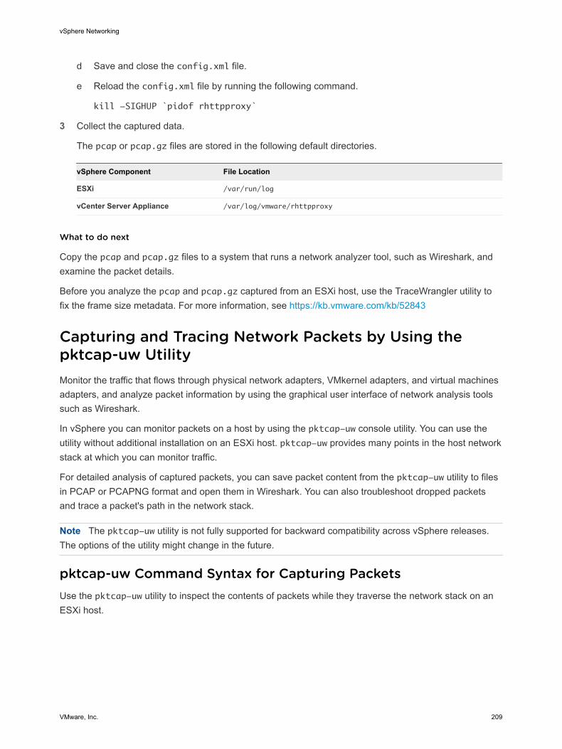
d Save and close the config.xml file.
e Reload the config.xml file by running the following command.
kill -SIGHUP `pidof rhttpproxy`
3 Collect the captured data.
The pcap or pcap.gz files are stored in the following default directories.
vSphere Component File Location
ESXi /var/run/log
vCenter Server Appliance /var/log/vmware/rhttpproxy
What to do next
Copy the pcap and pcap.gz files to a system that runs a network analyzer tool, such as Wireshark, and examine the packet details.
Before you analyze the pcap and pcap.gz captured from an ESXi host, use the TraceWrangler utility to fix the frame size metadata. For more information, see https://kb.vmware.com/kb/52843
Capturing and Tracing Network Packets by Using the pktcap-uw UtilityMonitor the traffic that flows through physical network adapters, VMkernel adapters, and virtual machines adapters, and analyze packet information by using the graphical user interface of network analysis tools such as Wireshark.
In vSphere you can monitor packets on a host by using the pktcap-uw console utility. You can use the utility without additional installation on an ESXi host. pktcap-uw provides many points in the host network stack at which you can monitor traffic.
For detailed analysis of captured packets, you can save packet content from the pktcap-uw utility to files in PCAP or PCAPNG format and open them in Wireshark. You can also troubleshoot dropped packets and trace a packet's path in the network stack.
Note The pktcap-uw utility is not fully supported for backward compatibility across vSphere releases. The options of the utility might change in the future.
pktcap-uw Command Syntax for Capturing PacketsUse the pktcap-uw utility to inspect the contents of packets while they traverse the network stack on an ESXi host.
vSphere Networking
VMware, Inc. 209
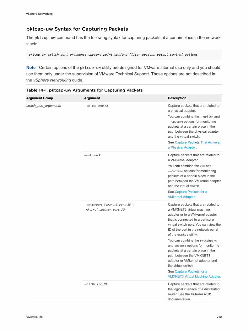
pktcap-uw Syntax for Capturing PacketsThe pktcap-uw command has the following syntax for capturing packets at a certain place in the network stack:
pktcap-uw switch_port_arguments capture_point_options filter_options output_control_options
Note Certain options of the pktcap-uw utility are designed for VMware internal use only and you should use them only under the supervision of VMware Technical Support. These options are not described in the vSphere Networking guide.
Table 14-1. pktcap-uw Arguments for Capturing Packets
Argument Group Argument Description
switch_port_arguments --uplink vmnicX Capture packets that are related to a physical adapter.
You can combine the --uplink and --capture options for monitoring packets at a certain place in the path between the physical adapter and the virtual switch.
See Capture Packets That Arrive at a Physical Adapter.
--vmk vmkX Capture packets that are related to a VMKernel adapter.
You can combine the vmk and --capture options for monitoring packets at a certain place in the path between the VMkernel adapter and the virtual switch.
See Capture Packets for a VMkernel Adapter.
--switchport {vmxnet3_port_ID |
vmkernel_adapter_port_ID}
Capture packets that are related to a VMXNET3 virtual machine adapter or to a VMkernel adapter that is connected to a particular virtual switch port. You can view the ID of the port in the network panel of the esxtop utility.
You can combine the switchport and capture options for monitoring packets at a certain place in the path between the VMXNET3 adapter or VMkernel adapter and the virtual switch.
See Capture Packets for a VMXNET3 Virtual Machine Adapter.
--lifID lif_ID Capture packets that are related to the logical interface of a distributed router. See the VMware NSX documentation.
vSphere Networking
VMware, Inc. 210
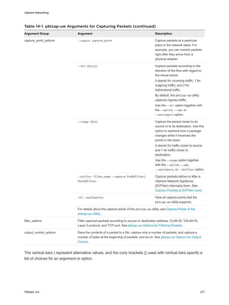
Table 14-1. pktcap-uw Arguments for Capturing Packets (continued)
Argument Group Argument Description
capture_point_options --capture capture_point Capture packets at a particular place in the network stack. For example, you can monitor packets right after they arrive from a physical adapter.
--dir {0|1|2} Capture packets according to the direction of the flow with regard to the virtual switch.
0 stands for incoming traffic, 1 for outgoing traffic, and 2 for bidirectional traffic.
By default, the pktcap-uw utility captures ingress traffic.
Use the --dir option together with the --uplink, --vmk, or --switchport option.
--stage {0|1} Capture the packet closer to its source or to its destination. Use this option to examine how a package changes while it traverses the points in the stack.
0 stands for traffic closer to source and 1 for traffic closer to destination.
Use the --stage option together with the --uplink, --vmk , --switchport, or --dvfilter option.
--dvfilter filter_name --capture PreDVFilter|
PostDVFilter
Capture packets before or after a vSphere Network Appliance (DVFilter) intercepts them. See Capture Packets at DVFilter Level.
-A | --availpoints View all capture points that the pktcap-uw utility supports.
For details about the capture points of the pktcap-uw utility, see Capture Points of the pktcap-uw Utility.
filter_options Filter captured packets according to source or destination address, VLAN ID, VXLAN ID, Layer 3 protocol, and TCP port. See pktcap-uw Options for Filtering Packets.
output_control_options Save the contents of a packet to a file, capture only a number of packets, and capture a number of bytes at the beginning of packets, and so on. See pktcap-uw Options for Output Control.
The vertical bars | represent alternative values, and the curly brackets {} used with vertical bars specify a list of choices for an argument or option.
vSphere Networking
VMware, Inc. 211
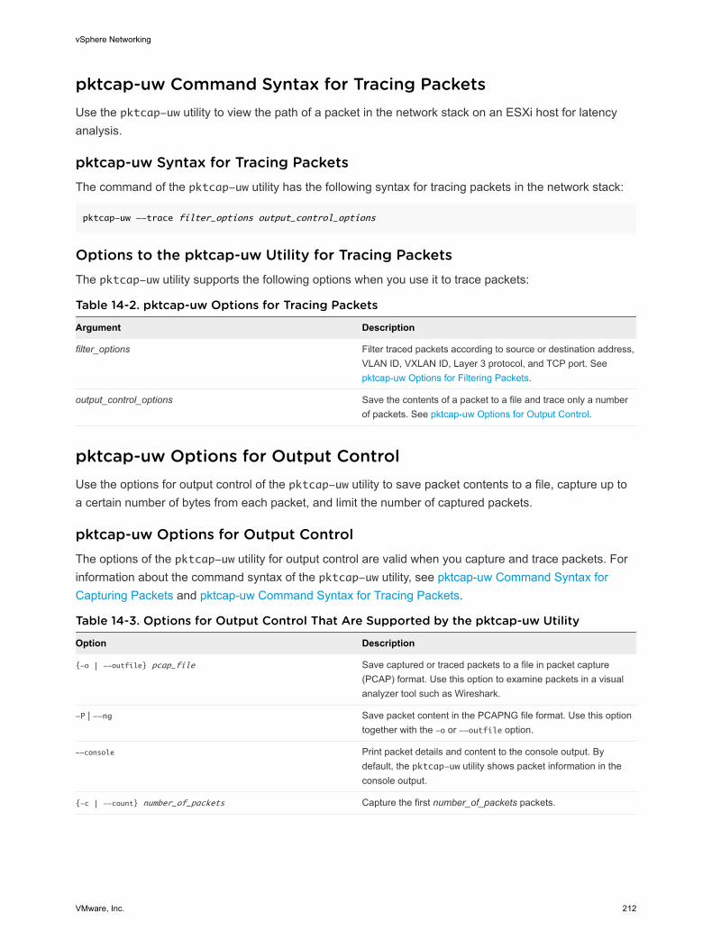
pktcap-uw Command Syntax for Tracing PacketsUse the pktcap-uw utility to view the path of a packet in the network stack on an ESXi host for latency analysis.
pktcap-uw Syntax for Tracing PacketsThe command of the pktcap-uw utility has the following syntax for tracing packets in the network stack:
pktcap-uw --trace filter_options output_control_options
Options to the pktcap-uw Utility for Tracing PacketsThe pktcap-uw utility supports the following options when you use it to trace packets:
Table 14-2. pktcap-uw Options for Tracing Packets
Argument Description
filter_options Filter traced packets according to source or destination address, VLAN ID, VXLAN ID, Layer 3 protocol, and TCP port. See pktcap-uw Options for Filtering Packets.
output_control_options Save the contents of a packet to a file and trace only a number of packets. See pktcap-uw Options for Output Control.
pktcap-uw Options for Output ControlUse the options for output control of the pktcap-uw utility to save packet contents to a file, capture up to a certain number of bytes from each packet, and limit the number of captured packets.
pktcap-uw Options for Output ControlThe options of the pktcap-uw utility for output control are valid when you capture and trace packets. For information about the command syntax of the pktcap-uw utility, see pktcap-uw Command Syntax for Capturing Packets and pktcap-uw Command Syntax for Tracing Packets.
Table 14-3. Options for Output Control That Are Supported by the pktcap-uw Utility
Option Description
{-o | --outfile} pcap_file Save captured or traced packets to a file in packet capture (PCAP) format. Use this option to examine packets in a visual analyzer tool such as Wireshark.
-P | --ng Save packet content in the PCAPNG file format. Use this option together with the -o or --outfile option.
--console Print packet details and content to the console output. By default, the pktcap-uw utility shows packet information in the console output.
{-c | --count} number_of_packets Capture the first number_of_packets packets.
vSphere Networking
VMware, Inc. 212
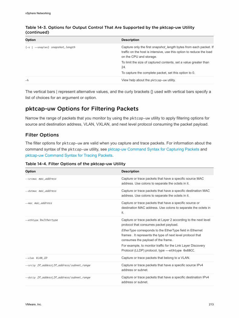
Table 14-3. Options for Output Control That Are Supported by the pktcap-uw Utility (continued)
Option Description
{-s | --snaplen} snapshot_length Capture only the first snapshot_length bytes from each packet. If traffic on the host is intensive, use this option to reduce the load on the CPU and storage.
To limit the size of captured contents, set a value greater than 24.
To capture the complete packet, set this option to 0.
-h View help about the pktcap-uw utility.
The vertical bars | represent alternative values, and the curly brackets {} used with vertical bars specify a list of choices for an argument or option.
pktcap-uw Options for Filtering PacketsNarrow the range of packets that you monitor by using the pktcap-uw utility to apply filtering options for source and destination address, VLAN, VXLAN, and next level protocol consuming the packet payload.
Filter OptionsThe filter options for pktcap-uw are valid when you capture and trace packets. For information about the command syntax of the pktcap-uw utility, see pktcap-uw Command Syntax for Capturing Packets and pktcap-uw Command Syntax for Tracing Packets.
Table 14-4. Filter Options of the pktcap-uw Utility
Option Description
--srcmac mac_address Capture or trace packets that have a specific source MAC address. Use colons to separate the octets in it.
--dstmac mac_address Capture or trace packets that have a specific destination MAC address. Use colons to separate the octets in it.
--mac mac_address Capture or trace packets that have a specific source or destination MAC address. Use colons to separate the octets in it.
--ethtype 0xEthertype Capture or trace packets at Layer 2 according to the next level protocol that consumes packet payload.
EtherType corresponds to the EtherType field in Ethernet frames . It represents the type of next level protocol that consumes the payload of the frame.
For example, to monitor traffic for the Link Layer Discovery Protocol (LLDP) protocol, type --ethtype 0x88CC.
--vlan VLAN_ID Capture or trace packets that belong to a VLAN.
--srcip IP_addess|IP_address/subnet_range Capture or trace packets that have a specific source IPv4 address or subnet.
--dstip IP_addess|IP_address/subnet_range Capture or trace packets that have a specific destination IPv4 address or subnet.
vSphere Networking
VMware, Inc. 213
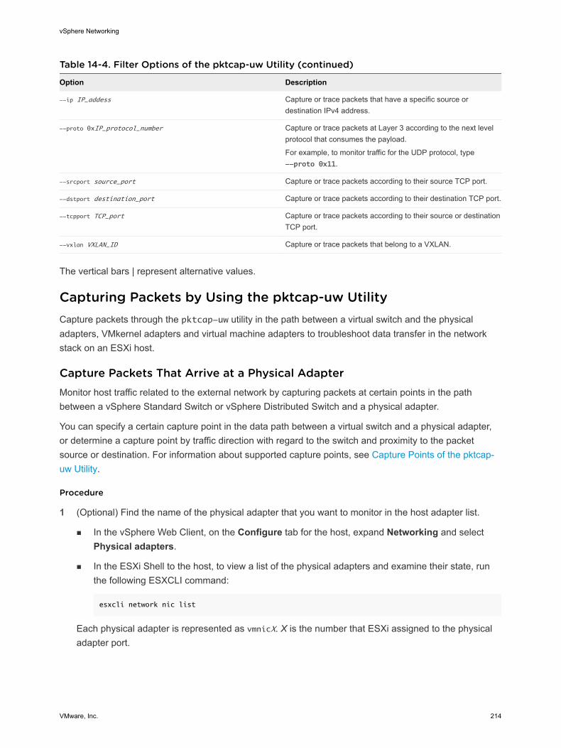
Table 14-4. Filter Options of the pktcap-uw Utility (continued)
Option Description
--ip IP_addess Capture or trace packets that have a specific source or destination IPv4 address.
--proto 0xIP_protocol_number Capture or trace packets at Layer 3 according to the next level protocol that consumes the payload.
For example, to monitor traffic for the UDP protocol, type --proto 0x11.
--srcport source_port Capture or trace packets according to their source TCP port.
--dstport destination_port Capture or trace packets according to their destination TCP port.
--tcpport TCP_port Capture or trace packets according to their source or destination TCP port.
--vxlan VXLAN_ID Capture or trace packets that belong to a VXLAN.
The vertical bars | represent alternative values.
Capturing Packets by Using the pktcap-uw UtilityCapture packets through the pktcap-uw utility in the path between a virtual switch and the physical adapters, VMkernel adapters and virtual machine adapters to troubleshoot data transfer in the network stack on an ESXi host.
Capture Packets That Arrive at a Physical AdapterMonitor host traffic related to the external network by capturing packets at certain points in the path between a vSphere Standard Switch or vSphere Distributed Switch and a physical adapter.
You can specify a certain capture point in the data path between a virtual switch and a physical adapter, or determine a capture point by traffic direction with regard to the switch and proximity to the packet source or destination. For information about supported capture points, see Capture Points of the pktcap-uw Utility.
Procedure
1 (Optional) Find the name of the physical adapter that you want to monitor in the host adapter list.
n In the vSphere Web Client, on the Configure tab for the host, expand Networking and select Physical adapters.
n In the ESXi Shell to the host, to view a list of the physical adapters and examine their state, run the following ESXCLI command:
esxcli network nic list
Each physical adapter is represented as vmnicX. X is the number that ESXi assigned to the physical adapter port.
vSphere Networking
VMware, Inc. 214
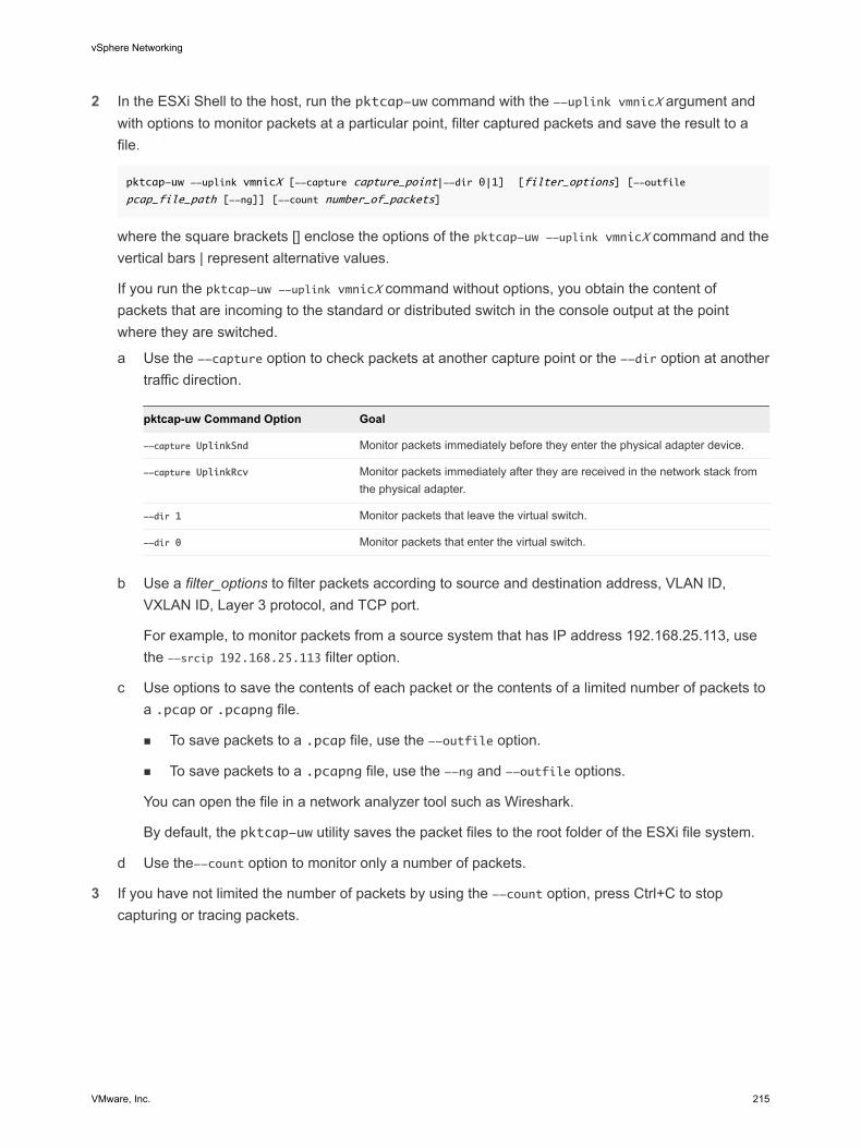
2 In the ESXi Shell to the host, run the pktcap-uw command with the --uplink vmnicX argument and with options to monitor packets at a particular point, filter captured packets and save the result to a file.
pktcap-uw --uplink vmnicX [--capture capture_point|--dir 0|1] [filter_options] [--outfile
pcap_file_path [--ng]] [--count number_of_packets]
where the square brackets [] enclose the options of the pktcap-uw --uplink vmnicX command and the vertical bars | represent alternative values.
If you run the pktcap-uw --uplink vmnicX command without options, you obtain the content of packets that are incoming to the standard or distributed switch in the console output at the point where they are switched.
a Use the --capture option to check packets at another capture point or the --dir option at another traffic direction.
pktcap-uw Command Option Goal
--capture UplinkSnd Monitor packets immediately before they enter the physical adapter device.
--capture UplinkRcv Monitor packets immediately after they are received in the network stack from the physical adapter.
--dir 1 Monitor packets that leave the virtual switch.
--dir 0 Monitor packets that enter the virtual switch.
b Use a filter_options to filter packets according to source and destination address, VLAN ID, VXLAN ID, Layer 3 protocol, and TCP port.
For example, to monitor packets from a source system that has IP address 192.168.25.113, use the --srcip 192.168.25.113 filter option.
c Use options to save the contents of each packet or the contents of a limited number of packets to a .pcap or .pcapng file.
n To save packets to a .pcap file, use the --outfile option.
n To save packets to a .pcapng file, use the --ng and --outfile options.
You can open the file in a network analyzer tool such as Wireshark.
By default, the pktcap-uw utility saves the packet files to the root folder of the ESXi file system.
d Use the--count option to monitor only a number of packets.
3 If you have not limited the number of packets by using the --count option, press Ctrl+C to stop capturing or tracing packets.
vSphere Networking
VMware, Inc. 215
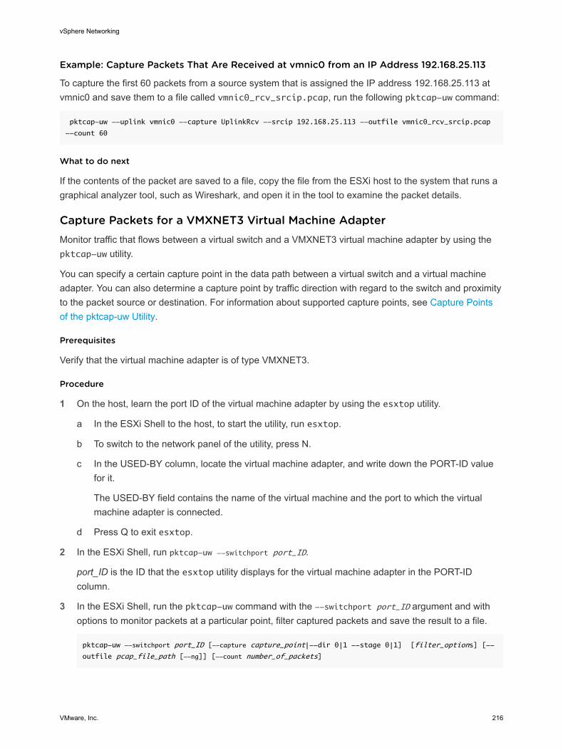
Example: Capture Packets That Are Received at vmnic0 from an IP Address 192.168.25.113
To capture the first 60 packets from a source system that is assigned the IP address 192.168.25.113 at vmnic0 and save them to a file called vmnic0_rcv_srcip.pcap, run the following pktcap-uw command:
pktcap-uw --uplink vmnic0 --capture UplinkRcv --srcip 192.168.25.113 --outfile vmnic0_rcv_srcip.pcap
--count 60
What to do next
If the contents of the packet are saved to a file, copy the file from the ESXi host to the system that runs a graphical analyzer tool, such as Wireshark, and open it in the tool to examine the packet details.
Capture Packets for a VMXNET3 Virtual Machine AdapterMonitor traffic that flows between a virtual switch and a VMXNET3 virtual machine adapter by using the pktcap-uw utility.
You can specify a certain capture point in the data path between a virtual switch and a virtual machine adapter. You can also determine a capture point by traffic direction with regard to the switch and proximity to the packet source or destination. For information about supported capture points, see Capture Points of the pktcap-uw Utility.
Prerequisites
Verify that the virtual machine adapter is of type VMXNET3.
Procedure
1 On the host, learn the port ID of the virtual machine adapter by using the esxtop utility.
a In the ESXi Shell to the host, to start the utility, run esxtop.
b To switch to the network panel of the utility, press N.
c In the USED-BY column, locate the virtual machine adapter, and write down the PORT-ID value for it.
The USED-BY field contains the name of the virtual machine and the port to which the virtual machine adapter is connected.
d Press Q to exit esxtop.
2 In the ESXi Shell, run pktcap-uw --switchport port_ID.
port_ID is the ID that the esxtop utility displays for the virtual machine adapter in the PORT-ID column.
3 In the ESXi Shell, run the pktcap-uw command with the --switchport port_ID argument and with options to monitor packets at a particular point, filter captured packets and save the result to a file.
pktcap-uw --switchport port_ID [--capture capture_point|--dir 0|1 --stage 0|1] [filter_options] [--
outfile pcap_file_path [--ng]] [--count number_of_packets]
vSphere Networking
VMware, Inc. 216
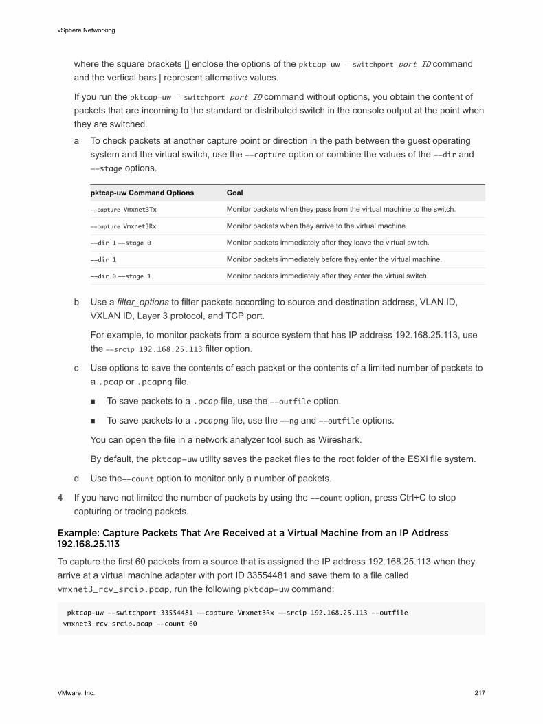
where the square brackets [] enclose the options of the pktcap-uw --switchport port_ID command and the vertical bars | represent alternative values.
If you run the pktcap-uw --switchport port_ID command without options, you obtain the content of packets that are incoming to the standard or distributed switch in the console output at the point when they are switched.
a To check packets at another capture point or direction in the path between the guest operating system and the virtual switch, use the --capture option or combine the values of the --dir and --stage options.
pktcap-uw Command Options Goal
--capture Vmxnet3Tx Monitor packets when they pass from the virtual machine to the switch.
--capture Vmxnet3Rx Monitor packets when they arrive to the virtual machine.
--dir 1 --stage 0 Monitor packets immediately after they leave the virtual switch.
--dir 1 Monitor packets immediately before they enter the virtual machine.
--dir 0 --stage 1 Monitor packets immediately after they enter the virtual switch.
b Use a filter_options to filter packets according to source and destination address, VLAN ID, VXLAN ID, Layer 3 protocol, and TCP port.
For example, to monitor packets from a source system that has IP address 192.168.25.113, use the --srcip 192.168.25.113 filter option.
c Use options to save the contents of each packet or the contents of a limited number of packets to a .pcap or .pcapng file.
n To save packets to a .pcap file, use the --outfile option.
n To save packets to a .pcapng file, use the --ng and --outfile options.
You can open the file in a network analyzer tool such as Wireshark.
By default, the pktcap-uw utility saves the packet files to the root folder of the ESXi file system.
d Use the--count option to monitor only a number of packets.
4 If you have not limited the number of packets by using the --count option, press Ctrl+C to stop capturing or tracing packets.
Example: Capture Packets That Are Received at a Virtual Machine from an IP Address 192.168.25.113
To capture the first 60 packets from a source that is assigned the IP address 192.168.25.113 when they arrive at a virtual machine adapter with port ID 33554481 and save them to a file called vmxnet3_rcv_srcip.pcap, run the following pktcap-uw command:
pktcap-uw --switchport 33554481 --capture Vmxnet3Rx --srcip 192.168.25.113 --outfile
vmxnet3_rcv_srcip.pcap --count 60
vSphere Networking
VMware, Inc. 217

What to do next
If the contents of the packet are saved to a file, copy the file from the ESXi host to the system that runs a graphical analyzer tool, such as Wireshark, and open it in the tool to examine the packet details.
Capture Packets for a VMkernel AdapterMonitor packets that are exchanged between a VMkernel adapter and a virtual switch by using the pktcap-uw utility.
You can capture packets at a certain capture point in the flow between a virtual switch and a VMkernel adapter. You can also determine a capture point by traffic direction with regard to the switch and proximity to the packet source or destination. For information about supported capture points, see Capture Points of the pktcap-uw Utility.
Procedure
1 (Optional) Find the name of the VMkernel adapter that you want to monitor in the VMkernel adapter list.
n In the vSphere Web Client, expand Networking on the Configure tab for the host and select VMkernel adapters.
n In the ESXi Shell to the host, to view a list of the physical adapters, run the following console command:
esxcli network ip interface list
Each VMkernel adapter is represented as vmkX, where X is the sequence number that ESXi assigned to the adapter.
2 In the ESXi Shell to the host, run the pktcap-uw command with the --vmk vmkX argument and with options to monitor packets at a particular point, filter captured packets and save the result to a file.
pktcap-uw --vmk vmkX [--capture capture_point|--dir 0|1 --stage 0|1] [filter_options] [--outfile
pcap_file_path [--ng]] [--count number_of_packets]
where the square brackets [] enclose the options of the pktcap-uw --vmk vmkX command and the vertical bars | represent alternative values.
You can replace the --vmk vmkX option with --switchport vmkernel_adapter_port_ID, where vmkernel_adapter_port_ID is the PORT-ID value that the network panel of the esxtop utility displays for the adapter.
vSphere Networking
VMware, Inc. 218
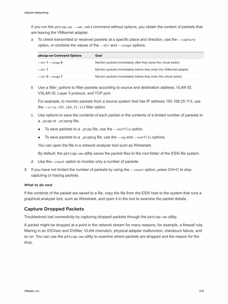
If you run the pktcap-uw --vmk vmkX command without options, you obtain the content of packets that are leaving the VMkernel adapter.
a To check transmitted or received packets at a specific place and direction, use the --capture option, or combine the values of the --dir and --stage options.
pktcap-uw Command Options Goal
--dir 1 --stage 0 Monitor packets immediately after they leave the virtual switch.
--dir 1 Monitor packets immediately before they enter the VMkernel adapter.
--dir 0 --stage 1 Monitor packets immediately before they enter the virtual switch.
b Use a filter_options to filter packets according to source and destination address, VLAN ID, VXLAN ID, Layer 3 protocol, and TCP port.
For example, to monitor packets from a source system that has IP address 192.168.25.113, use the --srcip 192.168.25.113 filter option.
c Use options to save the contents of each packet or the contents of a limited number of packets to a .pcap or .pcapng file.
n To save packets to a .pcap file, use the --outfile option.
n To save packets to a .pcapng file, use the --ng and --outfile options.
You can open the file in a network analyzer tool such as Wireshark.
By default, the pktcap-uw utility saves the packet files to the root folder of the ESXi file system.
d Use the--count option to monitor only a number of packets.
3 If you have not limited the number of packets by using the --count option, press Ctrl+C to stop capturing or tracing packets.
What to do next
If the contents of the packet are saved to a file, copy the file from the ESXi host to the system that runs a graphical analyzer tool, such as Wireshark, and open it in the tool to examine the packet details.
Capture Dropped PacketsTroubleshoot lost connectivity by capturing dropped packets through the pktcap-uw utility.
A packet might be dropped at a point in the network stream for many reasons, for example, a firewall rule, filtering in an IOChain and DVfilter, VLAN mismatch, physical adapter malfunction, checksum failure, and so on. You can use the pktcap-uw utility to examine where packets are dropped and the reason for the drop.
vSphere Networking
VMware, Inc. 219
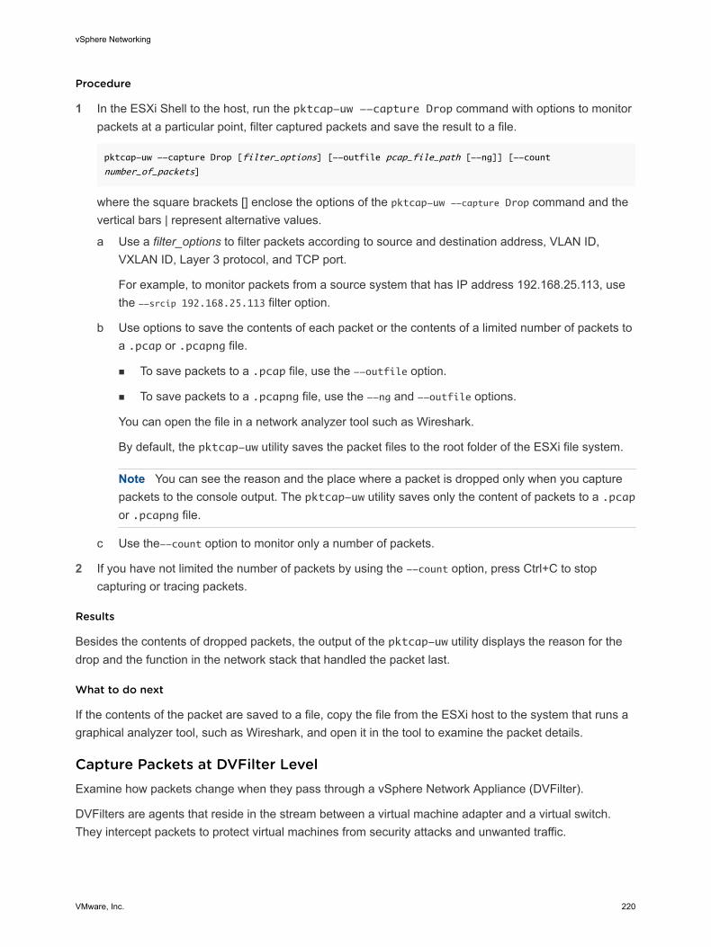
Procedure
1 In the ESXi Shell to the host, run the pktcap-uw --capture Drop command with options to monitor packets at a particular point, filter captured packets and save the result to a file.
pktcap-uw --capture Drop [filter_options] [--outfile pcap_file_path [--ng]] [--count
number_of_packets]
where the square brackets [] enclose the options of the pktcap-uw --capture Drop command and the vertical bars | represent alternative values.
a Use a filter_options to filter packets according to source and destination address, VLAN ID, VXLAN ID, Layer 3 protocol, and TCP port.
For example, to monitor packets from a source system that has IP address 192.168.25.113, use the --srcip 192.168.25.113 filter option.
b Use options to save the contents of each packet or the contents of a limited number of packets to a .pcap or .pcapng file.
n To save packets to a .pcap file, use the --outfile option.
n To save packets to a .pcapng file, use the --ng and --outfile options.
You can open the file in a network analyzer tool such as Wireshark.
By default, the pktcap-uw utility saves the packet files to the root folder of the ESXi file system.
Note You can see the reason and the place where a packet is dropped only when you capture packets to the console output. The pktcap-uw utility saves only the content of packets to a .pcap or .pcapng file.
c Use the--count option to monitor only a number of packets.
2 If you have not limited the number of packets by using the --count option, press Ctrl+C to stop capturing or tracing packets.
Results
Besides the contents of dropped packets, the output of the pktcap-uw utility displays the reason for the drop and the function in the network stack that handled the packet last.
What to do next
If the contents of the packet are saved to a file, copy the file from the ESXi host to the system that runs a graphical analyzer tool, such as Wireshark, and open it in the tool to examine the packet details.
Capture Packets at DVFilter LevelExamine how packets change when they pass through a vSphere Network Appliance (DVFilter).
DVFilters are agents that reside in the stream between a virtual machine adapter and a virtual switch. They intercept packets to protect virtual machines from security attacks and unwanted traffic.
vSphere Networking
VMware, Inc. 220
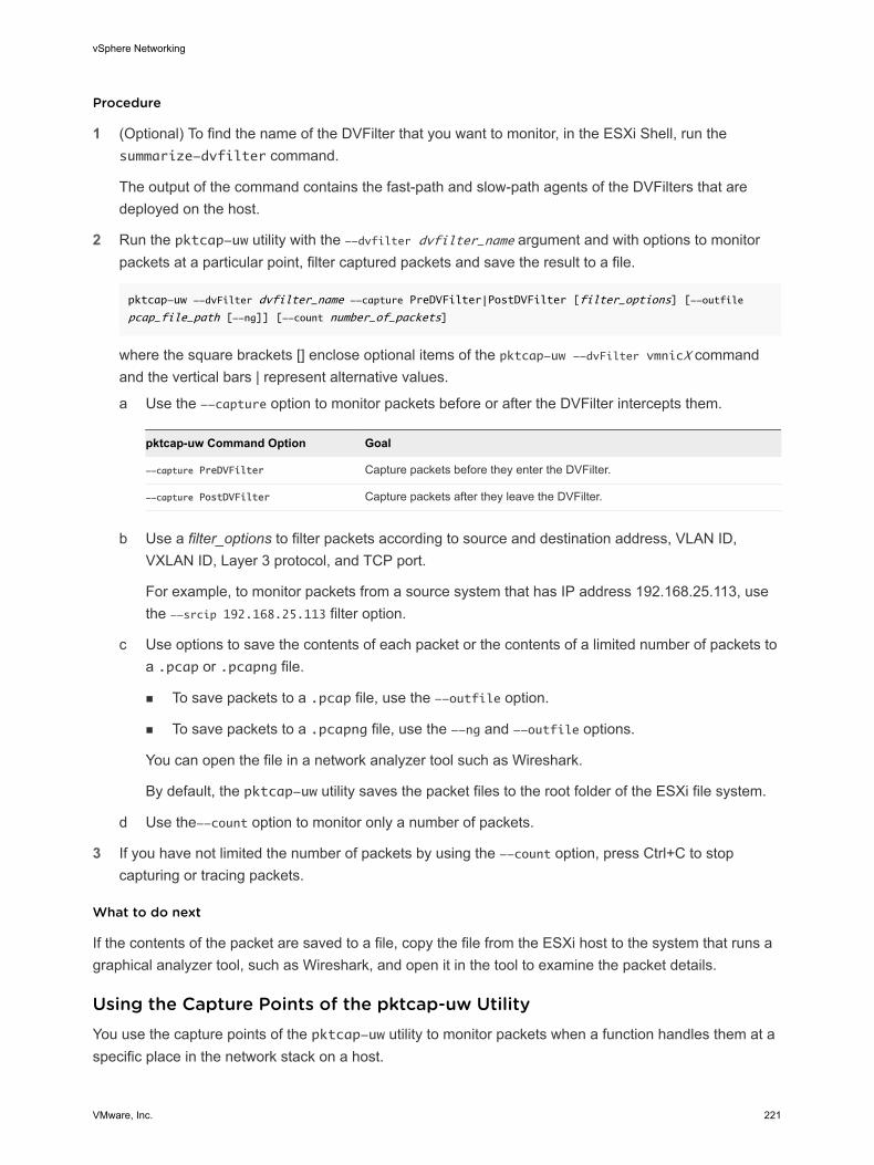
Procedure
1 (Optional) To find the name of the DVFilter that you want to monitor, in the ESXi Shell, run the summarize-dvfilter command.
The output of the command contains the fast-path and slow-path agents of the DVFilters that are deployed on the host.
2 Run the pktcap-uw utility with the --dvfilter dvfilter_name argument and with options to monitor packets at a particular point, filter captured packets and save the result to a file.
pktcap-uw --dvFilter dvfilter_name --capture PreDVFilter|PostDVFilter [filter_options] [--outfile
pcap_file_path [--ng]] [--count number_of_packets]
where the square brackets [] enclose optional items of the pktcap-uw --dvFilter vmnicX command and the vertical bars | represent alternative values.
a Use the --capture option to monitor packets before or after the DVFilter intercepts them.
pktcap-uw Command Option Goal
--capture PreDVFilter Capture packets before they enter the DVFilter.
--capture PostDVFilter Capture packets after they leave the DVFilter.
b Use a filter_options to filter packets according to source and destination address, VLAN ID, VXLAN ID, Layer 3 protocol, and TCP port.
For example, to monitor packets from a source system that has IP address 192.168.25.113, use the --srcip 192.168.25.113 filter option.
c Use options to save the contents of each packet or the contents of a limited number of packets to a .pcap or .pcapng file.
n To save packets to a .pcap file, use the --outfile option.
n To save packets to a .pcapng file, use the --ng and --outfile options.
You can open the file in a network analyzer tool such as Wireshark.
By default, the pktcap-uw utility saves the packet files to the root folder of the ESXi file system.
d Use the--count option to monitor only a number of packets.
3 If you have not limited the number of packets by using the --count option, press Ctrl+C to stop capturing or tracing packets.
What to do next
If the contents of the packet are saved to a file, copy the file from the ESXi host to the system that runs a graphical analyzer tool, such as Wireshark, and open it in the tool to examine the packet details.
Using the Capture Points of the pktcap-uw UtilityYou use the capture points of the pktcap-uw utility to monitor packets when a function handles them at a specific place in the network stack on a host.
vSphere Networking
VMware, Inc. 221
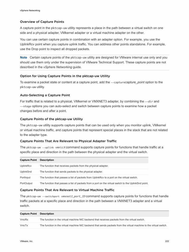
Overview of Capture Points
A capture point in the pktcap-uw utility represents a place in the path between a virtual switch on one side and a physical adapter, VMkernel adapter or a virtual machine adapter on the other.
You can use certain capture points in combination with an adapter option. For example, you use the UplinkRcv point when you capture uplink traffic. You can address other points standalone. For example, use the Drop point to inspect all dropped packets.
Note Certain capture points of the pktcap-uw utility are designed for VMware internal use only and you should use them only under the supervision of VMware Technical Support. These capture points are not described in the vSphere Networking guide.
Option for Using Capture Points in the pktcap-uw Utility
To examine a packet state or content at a capture point, add the --capturecapture_point option to the pktcap-uw utility.
Auto-Selecting a Capture Point
For traffic that is related to a physical, VMkernel or VMXNET3 adapter, by combining the --dir and --stage options you can auto-select and switch between capture points to examine how a packet changes before and after a point.
Capture Points of the pktcap-uw Utility
The pktcap-uw utility supports capture points that can be used only when you monitor uplink, VMkernel or virtual machine traffic, and capture points that represent special places in the stack that are not related to the adapter type.
Capture Points That Are Relevant to Physical Adapter Traffic
The pktcap-uw --uplink vmnicX command supports capture points for functions that handle traffic at a specific place and direction in the path between the physical adapter and the virtual switch.
Capture Point Description
UplinkRcv The function that receives packets from the physical adapter.
UplinkSnd The function that sends packets to the physical adapter.
PortInput The function that passes a list of packets from UplinkRcv to a port on the virtual switch.
PortOutput The function that passes a list of packets from a port on the virtual switch to the UplinkSnd point.
Capture Points That Are Relevant to Virtual Machine Traffic
The pktcap-uw --switchport vmxnet3_port_ID command supports capture points for functions that handle traffic packets at a specific place and direction in the path between a VMXNET3 adapter and a virtual switch.
Capture Point Description
VnicRx The function in the virtual machine NIC backend that receives packets from the virtual switch.
VnicTx The function in the virtual machine NIC backend that sends packets from the virtual machine to the virtual switch.
vSphere Networking
VMware, Inc. 222
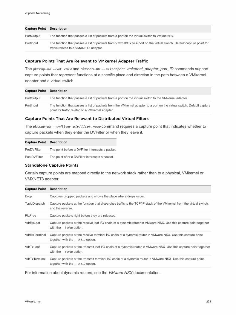
Capture Point Description
PortOutput The function that passes a list of packets from a port on the virtual switch to Vmxnet3Rx.
PortInput The function that passes a list of packets from Vmxnet3Tx to a port on the virtual switch. Default capture point for traffic related to a VMXNET3 adapter.
Capture Points That Are Relevant to VMkernel Adapter Traffic
The pktcap-uw --vmk vmkX and pktcap-uw --switchport vmkernel_adapter_port_ID commands support capture points that represent functions at a specific place and direction in the path between a VMkernel adapter and a virtual switch.
Capture Point Description
PortOutput The function that passes a list of packets from a port on the virtual switch to the VMkernel adapter.
PortInput The function that passes a list of packets from the VMkernel adapter to a port on the virtual switch. Default capture point for traffic related to a VMkernel adapter.
Capture Points That Are Relevant to Distributed Virtual Filters
The pktcap-uw --dvfilter divfilter_name command requires a capture point that indicates whether to capture packets when they enter the DVFilter or when they leave it.
Capture Point Description
PreDVFilter The point before a DVFilter intercepts a packet.
PostDVFilter The point after a DVFilter intercepts a packet.
Standalone Capture Points
Certain capture points are mapped directly to the network stack rather than to a physical, VMkernel or VMXNET3 adapter.
Capture Point Description
Drop Captures dropped packets and shows the place where drops occur.
TcpipDispatch Capture packets at the function that dispatches traffic to the TCP/IP stack of the VMkernel from the virtual switch, and the reverse.
PktFree Capture packets right before they are released.
VdrRxLeaf Capture packets at the receive leaf I/O chain of a dynamic router in VMware NSX. Use this capture point together with the --lifID option.
VdrRxTerminal Capture packets at the receive terminal I/O chain of a dynamic router in VMware NSX. Use this capture point together with the --lifID option.
VdrTxLeaf Capture packets at the transmit leaf I/O chain of a dynamic router in VMware NSX. Use this capture point together with the --lifID option.
VdrTxTerminal Capture packets at the transmit terminal I/O chain of a dynamic router in VMware NSX. Use this capture point together with the --lifID option.
For information about dynamic routers, see the VMware NSX documentation.
vSphere Networking
VMware, Inc. 223
List the Capture Points of the pktcap-uw Utility
View all capture points of the pktcap-uw utility to find the name of capture point for monitoring traffic at a certain place in the network stack on the ESXi host.
For information about the capture points of the pktcap-uw utility, see Capture Points of the pktcap-uw Utility.
Procedure
u In the ESXi Shell to the host, run the pktcap-uw -A command to view all capture points that the pktcap-uw utility supports.
Trace Packets by Using the pktcap-uw UtilityUse the pktcap-uw utility to trace the path that packets traverse in the network stack for latency analysis and for locating the point where a packet is corrupted or dropped.
The pktcap-uw utility shows the path of packets together with timestamps that note the time when a packet is handled by a networking function on ESXi. The utility reports the path of a packet immediately before it is released from the stack.
To view the full path information for a packet, you must print the result from the pktcap-uw utility in the console output or save it to a PCAPNG file.
Procedure
1 In the ESXi Shell to the host, run the pktcap-uw --trace command with options to filter traced packets, save the result to a file and limit the number of traced packets.
pktcap-uw --trace [filter_options] [--outfile pcap_file_path [--ng]] [--count number_of_packets]
vSphere Networking
VMware, Inc. 224
where the square brackets [] enclose optional items of the pktcap-uw --trace command and the vertical bars | represent alternative values.
a Use a filter_options to filter packets according to source and destination address, VLAN ID, VXLAN ID, Layer 3 protocol, and TCP port.
For example, to monitor packets from a source system that has IP address 192.168.25.113, use the --srcip 192.168.25.113 filter option.
b Use options to save the contents of each packet or the contents of a limited number of packets to a .pcap or .pcapng file.
n To save packets to a .pcap file, use the --outfile option.
n To save packets to a .pcapng file, use the --ng and --outfile options.
You can open the file in a network analyzer tool such as Wireshark.
By default, the pktcap-uw utility saves the packet files to the root folder of the ESXi file system.
Note A .pcap file contains only the contents of traced packets. To collect packet paths besides packet content, save the output to a .pcapng file.
c Use the--count option to monitor only a number of packets.
2 If you have not limited the number of packets by using the --count option, press Ctrl+C to stop capturing or tracing packets.
What to do next
If the contents of the packet are saved to a file, copy the file from the ESXi host to the system that runs a graphical analyzer tool, such as Wireshark, and open it in the tool to examine the packet details.
Configure the NetFlow Settings of a vSphere Distributed SwitchAnalyze virtual machine IP traffic that flows through a vSphere Distributed Switch by sending reports to a NetFlow collector.
vSphere Distributed Switch supports IPFIX (NetFlow version 10).
Procedure
1 In the vSphere Web Client, navigate to the distributed switch.
2 From the Actions menu, select Settings > Edit Netflow.
3 Type the Collector IP address and Collector port of the NetFlow collector.
You can contact the NetFlow collector by IPv4 or IPv6 address.
4 Set an Observation Domain ID that identifies the information related to the switch.
vSphere Networking
VMware, Inc. 225
5 To see the information from the distributed switch in the NetFlow collector under a single network device instead of under a separate device for each host on the switch, type an IPv4 address in the Switch IP address text box.
6 (Optional) In the Active flow export timeout and Idle flow export timeout text boxes, set the time, in seconds, to wait before sending information after the flow is initiated.
7 (Optional) To change the portion of data that the switch collects, configure Sampling Rate.
The sampling rate represents the number of packets that NetFlow drops after every collected packet. A sampling rate of x instructs NetFlow to drop packets in a collected packets:dropped packets ratio 1:x. If the rate is 0, NetFlow samples every packet, that is, collect one packet and drop none. If the rate is 1, NetFlow samples a packet and drops the next one, and so on.
8 (Optional) To collect data on network activity between virtual machines on the same host, enable Process internal flows only.
Collect internal flows only if NetFlow is enabled on the physical network device to avoid sending duplicate information from the distributed switch and the physical network device.
9 Click OK.
What to do next
Enable NetFlow reporting for traffic from virtual machines connected to a distributed port group or a port. See Enable or Disable NetFlow Monitoring on a Distributed Port Group or Distributed Port.
Working With Port MirroringPort mirroring allows you to mirror a distributed port's traffic to other distributed ports or specific physical switch ports.
Port mirroring is used on a switch to send a copy of packets seen on one switch port (or an entire VLAN) to a monitoring connection on another switch port. Port mirroring is used to analyze and debug data or diagnose errors on a network.
Port Mirroring InteroperabilityThere are some interoperability issues to consider when using vSphere port mirroring with other features of vSphere.
vMotionvMotion functions differently depending on which vSphere port mirroring session type you select. During vMotion, a mirroring path could be temporarily invalid, but it is restored when vMotion completes.
vSphere Networking
VMware, Inc. 226
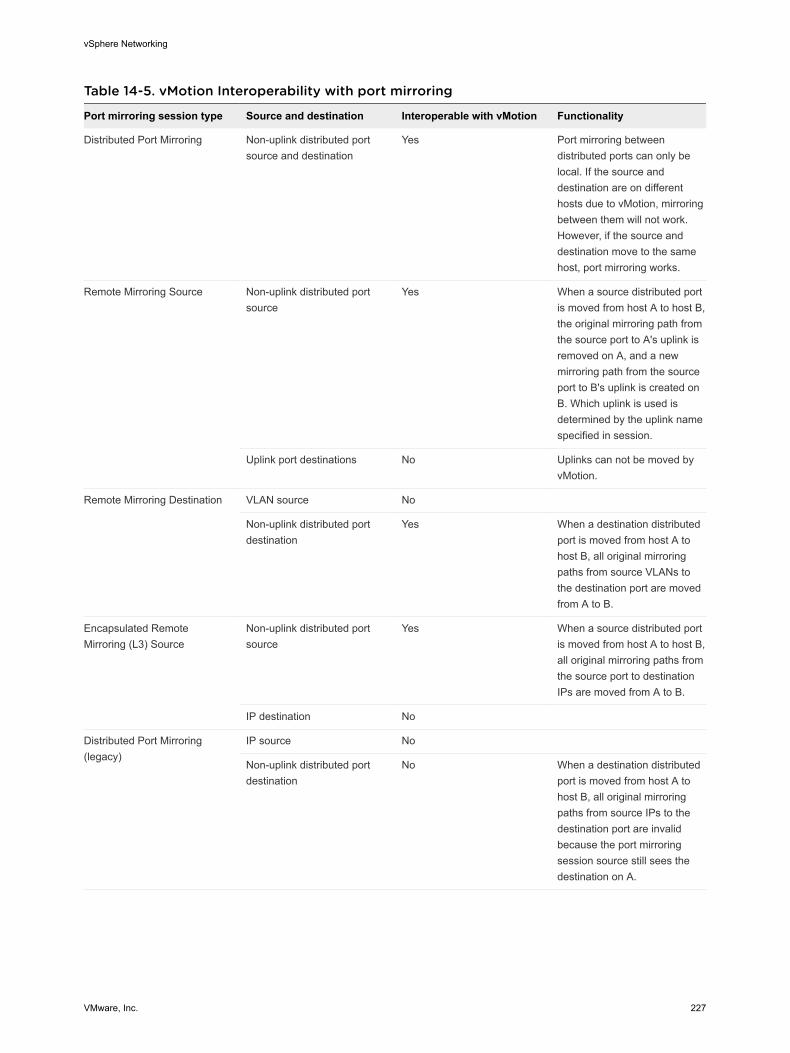
Table 14-5. vMotion Interoperability with port mirroring
Port mirroring session type Source and destination Interoperable with vMotion Functionality
Distributed Port Mirroring Non-uplink distributed port source and destination
Yes Port mirroring between distributed ports can only be local. If the source and destination are on different hosts due to vMotion, mirroring between them will not work. However, if the source and destination move to the same host, port mirroring works.
Remote Mirroring Source Non-uplink distributed port source
Yes When a source distributed port is moved from host A to host B, the original mirroring path from the source port to A's uplink is removed on A, and a new mirroring path from the source port to B's uplink is created on B. Which uplink is used is determined by the uplink name specified in session.
Uplink port destinations No Uplinks can not be moved by vMotion.
Remote Mirroring Destination VLAN source No
Non-uplink distributed port destination
Yes When a destination distributed port is moved from host A to host B, all original mirroring paths from source VLANs to the destination port are moved from A to B.
Encapsulated Remote Mirroring (L3) Source
Non-uplink distributed port source
Yes When a source distributed port is moved from host A to host B, all original mirroring paths from the source port to destination IPs are moved from A to B.
IP destination No
Distributed Port Mirroring (legacy)
IP source No
Non-uplink distributed port destination
No When a destination distributed port is moved from host A to host B, all original mirroring paths from source IPs to the destination port are invalid because the port mirroring session source still sees the destination on A.
vSphere Networking
VMware, Inc. 227
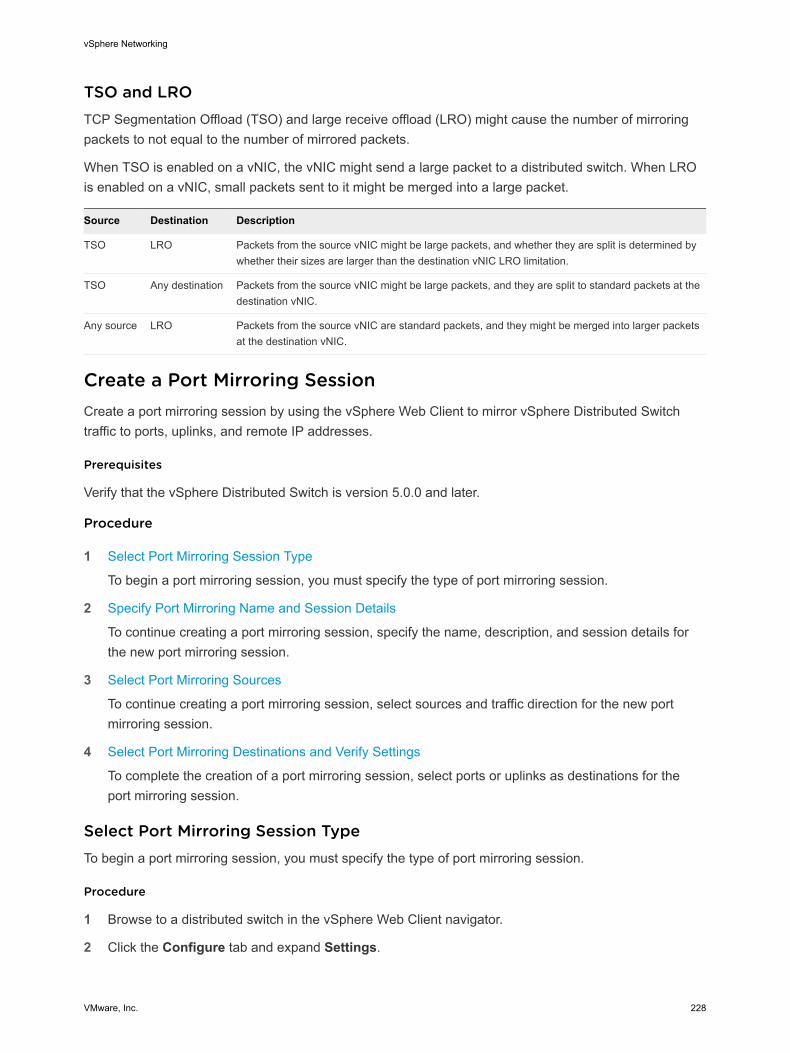
TSO and LROTCP Segmentation Offload (TSO) and large receive offload (LRO) might cause the number of mirroring packets to not equal to the number of mirrored packets.
When TSO is enabled on a vNIC, the vNIC might send a large packet to a distributed switch. When LRO is enabled on a vNIC, small packets sent to it might be merged into a large packet.
Source Destination Description
TSO LRO Packets from the source vNIC might be large packets, and whether they are split is determined by whether their sizes are larger than the destination vNIC LRO limitation.
TSO Any destination Packets from the source vNIC might be large packets, and they are split to standard packets at the destination vNIC.
Any source LRO Packets from the source vNIC are standard packets, and they might be merged into larger packets at the destination vNIC.
Create a Port Mirroring SessionCreate a port mirroring session by using the vSphere Web Client to mirror vSphere Distributed Switch traffic to ports, uplinks, and remote IP addresses.
Prerequisites
Verify that the vSphere Distributed Switch is version 5.0.0 and later.
Procedure
1 Select Port Mirroring Session Type
To begin a port mirroring session, you must specify the type of port mirroring session.
2 Specify Port Mirroring Name and Session Details
To continue creating a port mirroring session, specify the name, description, and session details for the new port mirroring session.
3 Select Port Mirroring Sources
To continue creating a port mirroring session, select sources and traffic direction for the new port mirroring session.
4 Select Port Mirroring Destinations and Verify Settings
To complete the creation of a port mirroring session, select ports or uplinks as destinations for the port mirroring session.
Select Port Mirroring Session TypeTo begin a port mirroring session, you must specify the type of port mirroring session.
Procedure
1 Browse to a distributed switch in the vSphere Web Client navigator.
2 Click the Configure tab and expand Settings.
vSphere Networking
VMware, Inc. 228
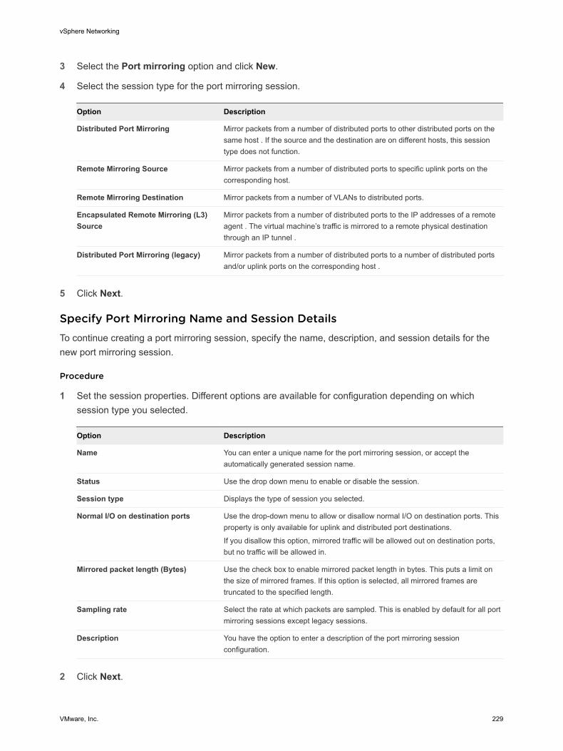
3 Select the Port mirroring option and click New.
4 Select the session type for the port mirroring session.
Option Description
Distributed Port Mirroring Mirror packets from a number of distributed ports to other distributed ports on the same host . If the source and the destination are on different hosts, this session type does not function.
Remote Mirroring Source Mirror packets from a number of distributed ports to specific uplink ports on the corresponding host.
Remote Mirroring Destination Mirror packets from a number of VLANs to distributed ports.
Encapsulated Remote Mirroring (L3) Source
Mirror packets from a number of distributed ports to the IP addresses of a remote agent . The virtual machine’s traffic is mirrored to a remote physical destination through an IP tunnel .
Distributed Port Mirroring (legacy) Mirror packets from a number of distributed ports to a number of distributed ports and/or uplink ports on the corresponding host .
5 Click Next.
Specify Port Mirroring Name and Session DetailsTo continue creating a port mirroring session, specify the name, description, and session details for the new port mirroring session.
Procedure
1 Set the session properties. Different options are available for configuration depending on which session type you selected.
Option Description
Name You can enter a unique name for the port mirroring session, or accept the automatically generated session name.
Status Use the drop down menu to enable or disable the session.
Session type Displays the type of session you selected.
Normal I/O on destination ports Use the drop-down menu to allow or disallow normal I/O on destination ports. This property is only available for uplink and distributed port destinations.
If you disallow this option, mirrored traffic will be allowed out on destination ports, but no traffic will be allowed in.
Mirrored packet length (Bytes) Use the check box to enable mirrored packet length in bytes. This puts a limit on the size of mirrored frames. If this option is selected, all mirrored frames are truncated to the specified length.
Sampling rate Select the rate at which packets are sampled. This is enabled by default for all port mirroring sessions except legacy sessions.
Description You have the option to enter a description of the port mirroring session configuration.
2 Click Next.
vSphere Networking
VMware, Inc. 229

Select Port Mirroring SourcesTo continue creating a port mirroring session, select sources and traffic direction for the new port mirroring session.
You can create a port mirroring session without setting the source and destinations. When a source and destination are not set, a port mirroring session is created without the mirroring path. This allows you to create a port mirroring session with the correct properties set. Once the properties are set, you can edit the port mirroring session to add the source and destination information.
Procedure
1 Select the source of the traffic to be mirrored and the traffic direction.
Depending on the type of port mirroring session you selected, different options are available for configuration.
Option Description
Add existing ports from a list Click Select distributed ports. A dialog box displays a list of existing ports. Select the check box next to the distributed port and click OK. You can choose more than one distributed port.
Add existing ports by port number Click Add distributed ports, enter the port number and click OK.
Set the traffic direction After adding ports, select the port in the list and click the ingress, egress, or ingress/egress button. Your choice appears in the Traffic Direction column.
Specify the source VLAN If you selected a Remote Mirroring Destination sessions type, you must specify the source VLAN. ClickAdd to add a VLAN ID. Edit the ID by using the up and down arrows, or clicking in the field and entering the VLAN ID manually.
2 Click Next.
Select Port Mirroring Destinations and Verify SettingsTo complete the creation of a port mirroring session, select ports or uplinks as destinations for the port mirroring session.
You can create a port mirroring session without setting the source and destinations. When a source and destination are not set, a port mirroring session is created without the mirroring path. This allows you to create a port mirroring session with the correct properties set. Once the properties are set, you can edit the port mirroring session to add the source and destination information.
Port mirroring is checked against the VLAN forwarding policy. If the VLAN of the original frames is not equal to or trunked by the destination port, the frames are not mirrored.
vSphere Networking
VMware, Inc. 230
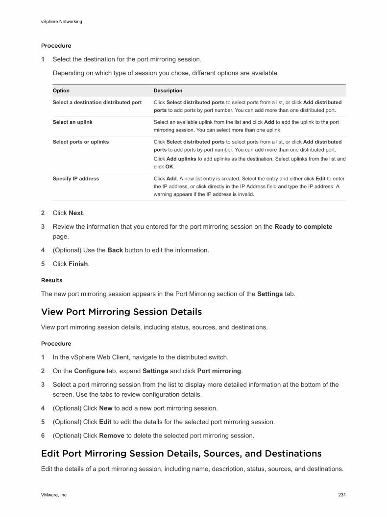
Procedure
1 Select the destination for the port mirroring session.
Depending on which type of session you chose, different options are available.
Option Description
Select a destination distributed port Click Select distributed ports to select ports from a list, or click Add distributed ports to add ports by port number. You can add more than one distributed port.
Select an uplink Select an available uplink from the list and click Add to add the uplink to the port mirroring session. You can select more than one uplink.
Select ports or uplinks Click Select distributed ports to select ports from a list, or click Add distributed ports to add ports by port number. You can add more than one distributed port.
Click Add uplinks to add uplinks as the destination. Select uplinks from the list and click OK.
Specify IP address Click Add. A new list entry is created. Select the entry and either click Edit to enter the IP address, or click directly in the IP Address field and type the IP address. A warning appears if the IP address is invalid.
2 Click Next.
3 Review the information that you entered for the port mirroring session on the Ready to complete page.
4 (Optional) Use the Back button to edit the information.
5 Click Finish.
Results
The new port mirroring session appears in the Port Mirroring section of the Settings tab.
View Port Mirroring Session DetailsView port mirroring session details, including status, sources, and destinations.
Procedure
1 In the vSphere Web Client, navigate to the distributed switch.
2 On the Configure tab, expand Settings and click Port mirroring.
3 Select a port mirroring session from the list to display more detailed information at the bottom of the screen. Use the tabs to review configuration details.
4 (Optional) Click New to add a new port mirroring session.
5 (Optional) Click Edit to edit the details for the selected port mirroring session.
6 (Optional) Click Remove to delete the selected port mirroring session.
Edit Port Mirroring Session Details, Sources, and DestinationsEdit the details of a port mirroring session, including name, description, status, sources, and destinations.
vSphere Networking
VMware, Inc. 231
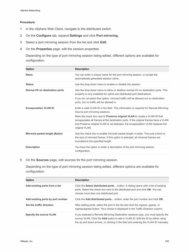
Procedure
1 In the vSphere Web Client, navigate to the distributed switch.
2 On the Configure tab, expand Settings and click Port mirroring.
3 Select a port mirroring session from the list and click Edit.
4 On the Properties page, edit the session properties.
Depending on the type of port mirroring session being edited, different options are available for configuration.
Option Description
Name You can enter a unique name for the port mirroring session, or accept the automatically generated session name.
Status Use the drop-down menu to enable or disable the session.
Normal I/O on destination ports Use the drop-down menu to allow or disallow normal I/O on destination ports. This property is only available for uplink and distributed port destinations.
If you do not select this option, mirrored traffic will be allowed out on destination ports, but no traffic will be allowed in.
Encapsulation VLAN ID Enter a valid VLAN ID in the field. This information is required for Remote Mirroring Source port mirroring sessions.
Mark the check box next to Preserve original VLAN to create a VLAN ID that encapsulates all frames at the destination ports. If the original frames have a VLAN and Preserve original VLAN is not selected, the encapsulation VLAN replaces the original VLAN.
Mirrored packet length (Bytes) Use the check box to enable mirrored packet length in bytes. This puts a limit on the size of mirrored frames. If this option is selected, all mirrored frames are truncated to the specified length.
Description You have the option to enter a description of the port mirroring session configuration.
5 On the Sources page, edit sources for the port mirroring session.
Depending on the type of port mirroring session being edited, different options are available for configuration.
Option Description
Add existing ports from a list Click the Select distributed ports… button. A dialog opens with a list of existing ports. Select the check box next to the distributed port and click OK. You can choose more than one distributed port.
Add existing ports by port number Click the Add distributed ports… button, enter the port number and click OK.
Set the traffic direction After adding ports, select the port in the list and click the ingress, egress, or ingress/egress button. Your choice is displayed in the Traffic Direction column.
Specify the source VLAN If you selected a Remote Mirroring Destination sessions type, you must specify the source VLAN. Click the Add button to add a VLAN ID. Edit the ID by either using the up and down arrows, or clicking in the field and entering the VLAN ID manually.
vSphere Networking
VMware, Inc. 232
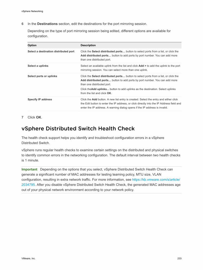
6 In the Destinations section, edit the destinations for the port mirroring session.
Depending on the type of port mirroring session being edited, different options are available for configuration.
Option Description
Select a destination distributed port Click the Select distributed ports… button to select ports from a list, or click the Add distributed ports… button to add ports by port number. You can add more than one distributed port.
Select a uplinks Select an available uplink from the list and click Add > to add the uplink to the port mirroring session. You can select more than one uplink.
Select ports or uplinks Click the Select distributed ports… button to select ports from a list, or click the Add distributed ports… button to add ports by port number. You can add more than one distributed port.
Click theAdd uplinks... button to add uplinks as the destination. Select uplinks from the list and click OK.
Specify IP address Click the Add button. A new list entry is created. Select the entry and either click the Edit button to enter the IP address, or click directly into the IP Address field and enter the IP address. A warning dialog opens if the IP address is invalid.
7 Click OK.
vSphere Distributed Switch Health CheckThe health check support helps you identify and troubleshoot configuration errors in a vSphere Distributed Switch.
vSphere runs regular health checks to examine certain settings on the distributed and physical switches to identify common errors in the networking configuration. The default interval between two health checks is 1 minute.
Important Depending on the options that you select, vSphere Distributed Switch Health Check can generate a significant number of MAC addresses for testing teaming policy, MTU size, VLAN configuration, resulting in extra network traffic. For more information, see https://kb.vmware.com/s/article/2034795. After you disable vSphere Distributed Switch Health Check, the generated MAC addresses age out of your physical network environment according to your network policy.
vSphere Networking
VMware, Inc. 233
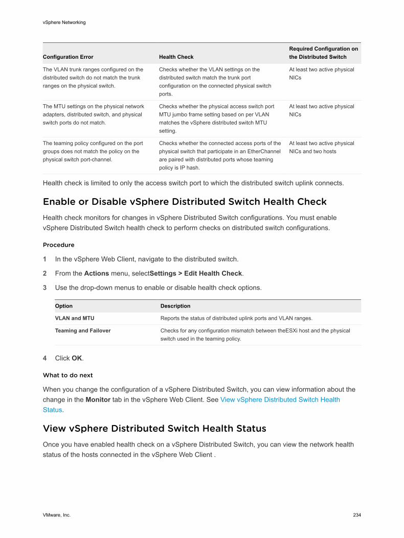
Configuration Error Health CheckRequired Configuration on the Distributed Switch
The VLAN trunk ranges configured on the distributed switch do not match the trunk ranges on the physical switch.
Checks whether the VLAN settings on the distributed switch match the trunk port configuration on the connected physical switch ports.
At least two active physical NICs
The MTU settings on the physical network adapters, distributed switch, and physical switch ports do not match.
Checks whether the physical access switch port MTU jumbo frame setting based on per VLAN matches the vSphere distributed switch MTU setting.
At least two active physical NICs
The teaming policy configured on the port groups does not match the policy on the physical switch port-channel.
Checks whether the connected access ports of the physical switch that participate in an EtherChannel are paired with distributed ports whose teaming policy is IP hash.
At least two active physical NICs and two hosts
Health check is limited to only the access switch port to which the distributed switch uplink connects.
Enable or Disable vSphere Distributed Switch Health CheckHealth check monitors for changes in vSphere Distributed Switch configurations. You must enable vSphere Distributed Switch health check to perform checks on distributed switch configurations.
Procedure
1 In the vSphere Web Client, navigate to the distributed switch.
2 From the Actions menu, selectSettings > Edit Health Check.
3 Use the drop-down menus to enable or disable health check options.
Option Description
VLAN and MTU Reports the status of distributed uplink ports and VLAN ranges.
Teaming and Failover Checks for any configuration mismatch between theESXi host and the physical switch used in the teaming policy.
4 Click OK.
What to do next
When you change the configuration of a vSphere Distributed Switch, you can view information about the change in the Monitor tab in the vSphere Web Client. See View vSphere Distributed Switch Health Status.
View vSphere Distributed Switch Health StatusOnce you have enabled health check on a vSphere Distributed Switch, you can view the network health status of the hosts connected in the vSphere Web Client .
vSphere Networking
VMware, Inc. 234
Prerequisites
Verify that health check for VLAN and MTU, and for teaming policy is enabled on the vSphere Distributed Switch. See Enable or Disable vSphere Distributed Switch Health Check.
Procedure
1 In the vSphere Web Client, navigate to the distributed switch.
2 On the Monitor tab, click Health.
3 In the Health Status Details section, examine the overall, VLAN, MTU and teaming health of the hosts connected to the switch.
Switch Discovery ProtocolSwitch discovery protocols help vSphere administrators to determine which port of the physical switch is connected to a vSphere standard switch or vSphere distributed switch.
vSphere 5.0 and later supports Cisco Discovery Protocol (CDP) and Link Layer Discovery Protocol (LLDP). CDP is available for vSphere standard switches and vSphere distributed switches connected to Cisco physical switches. LLDP is available for vSphere distributed switches version 5.0.0 and later.
When CDP or LLDP is enabled for a particular vSphere distributed switch or vSphere standard switch, you can view properties of the peer physical switch such as device ID, software version, and timeout from the vSphere Web Client.
Enable Cisco Discovery Protocol on a vSphere Distributed SwitchCisco Discovery Protocol (CDP) enables vSphere administrators to determine which port of a physical Cisco switch connects to a vSphere Standard Switch or vSphere Distributed Switch. When CDP is enabled for a vSphere Distributed Switch, you can view the properties of the Cisco switch such as device ID, software version, and timeout.
Procedure
1 In the vSphere Web Client, navigate to the distributed switch.
2 From the Actions menu, select Settings > Edit Settings.
3 In the Edit Settings dialog box, click Advanced.
4 In the Discovery Protocol section, select Cisco Discovery Protocol from the Type drop-down menu.
vSphere Networking
VMware, Inc. 235

5 From the Operation drop-down menu, select the operational mode of the ESXi hosts connected to the switch.
Option Description
Listen ESXi detects and displays information about the associated Cisco switch port, but information about the vSphere Distributed Switch is not available to the Cisco switch administrator.
Advertise ESXi makes information about the vSphere Distributed Switch available to the Cisco switch administrator, but does not detect and display information about the Cisco switch.
Both ESXi detects and displays information about the associated Cisco switch and makes information about the vSphere Distributed Switch available to the Cisco switch administrator.
6 Click OK.
Enable Link Layer Discovery Protocol on a vSphere Distributed SwitchWith Link Layer Discovery Protocol (LLDP), vSphere administrators can determine which physical switch port connects to a given vSphere Distributed Switch. When LLDP is enabled for a particular distributed switch, you can view properties of the physical switch (such as chassis ID, system name and description, and device capabilities) from the vSphere Web Client.
Procedure
1 In the vSphere Web Client, navigate to the distributed switch.
2 From the Actions menu, select Settings > Edit Settings.
3 In the Edit Settings dialog box, click Advanced.
4 In the Discovery Protocol section, select Link Layer Discovery Protocol from the Type drop-down menu.
5 From the Operation drop-down menu, select the operational mode of the ESXi hosts connected to the switch.
Operation Description
Listen ESXi detects and displays information about the associated physical switch port, but information about the vSphere Distributed Switch is not available to the switch administrator.
Advertise ESXi makes information about the vSphere Distributed Switch available to the switch administrator, but does not detect and display information about the physical switch.
Both ESXi detects and displays information about the associated physical switch and makes information about the vSphere Distributed Switch available to the switch administrator.
vSphere Networking
VMware, Inc. 236

6 Click OK.
View Switch InformationWhen Cisco Discovery Protocol (CDP) or Link Layer Discovery Protocol (LLDP) is enabled on the distributed switch and the hosts connected to the switch are in Listen or Both operational mode, you can view physical switch information from the vSphere Web Client.
Procedure
1 In the vSphere Web Client, navigate to the host.
2 On the Configure tab, expand Networking and click Physical adapters.
3 Select a physical adapter from the list to view its detailed information.
Results
According to the enabled switch discovery protocol, the properties of the switch appear under the CDP or LLDP tab. If the information is available in the network, under Peer device capability you can examine the system capabilities of the switch.
View the Topology Diagram of an NSX Virtual Distributed SwitchYou can examine the structure and components of an NSX Virtual Distributed Switch (N-VDS) by viewing its topology diagram.
From the diagram you can view the settings of a selected port group and of a selected adapter.
Prerequisites
The topology diagram of an N-VDS provides a visual representation of the adapters and port groups connected to the switch.
Procedure
1 In the vSphere Client, navigate to the host.
2 On the Configure tab, expand Networking and select Virtual switches.
3 Select the N-VDS from the list.
Results
The diagram appears under the list of virtual switches on the host.
What to do next
You can use the topology diagram to examine whether a virtual machine or VMkernel adapter is connected to the external network and to identify the physical adapter that carries the data.
vSphere Networking
VMware, Inc. 237
Configuring Protocol Profiles for Virtual Machine Networking 15A network protocol profile contains a pool of IPv4 and IPv6 addresses that vCenter Server assigns to vApps or to virtual machines with vApp functionality that are connected to port groups associated with the profile.
Network protocol profiles also contain settings for the IP subnet, DNS, and HTTP proxy server.
To configure the networking settings of virtual machines by using from network protocol profiles, perform the following operations:
n Create network profiles at the level of a data center or a vSphere distributed switch.
n Associate a protocol profile with the port group of a vApp virtual machine.
n Enable the transient or static IP allocation policy from the settings of the vApp or from the vApp options of a virtual machine.
Note If you move a vApp or a virtual machine that retrieves its network settings from a protocol profile to another data center, to power it on you must assign a protocol profile to the connected port group on the destination data center.
n Add a Network Protocol Profile
A network protocol profile contains a pool of IPv4 and IPv6 addresses. vCenter Server assigns those resources to vApps or to virtual machines with vApp functionality that are connected to port groups associated with the profile.
n Associate a Port Group with a Network Protocol Profile
To apply the range of IP addresses from a network protocol profile to a virtual machine that is a part of a vApp or has vApp functionality enabled, associate the profile with a port group that controls the networking of the virtual machine.
n Configure a Virtual Machine or vApp to Use a Network Protocol Profile
After you associate a protocol profile to a port group of a standard switch or a distributed switch, enable the usage of profile on a virtual machine that is connected to the port group and is associated with a vApp or has the vApp options enabled.
VMware, Inc. 238

Add a Network Protocol ProfileA network protocol profile contains a pool of IPv4 and IPv6 addresses. vCenter Server assigns those resources to vApps or to virtual machines with vApp functionality that are connected to port groups associated with the profile.
Network protocol profiles also contain settings for the IP subnet, DNS, and HTTP proxy server.
Note If you move a vApp or a virtual machine that retrieves its network settings from a protocol profile to another data center, to power on the vApp or virtual machine you must assign a protocol profile to the connected port group on the destination data center.
Procedure
1 Navigate to a data center that is associated with the vApp and click the Configure tab.
2 Click Network Protocol Profiles
Existing network protocol profiles are listed.
3 Click the Add icon ( ) to add a new network protocol profile.
Select the Network Protocol Profile Name and NetworkName the network protocol profile and select the network that should use it.
Procedure
1 Type the name of the network protocol profile.
2 Select the networks that use this network protocol profile.
A network can be associated with one network protocol profile at a time.
3 Click Next.
Specify Network Protocol Profile IPv4 ConfigurationA network protocol profile contains a pool of IPv4 and IPv6 addresses for use by vApps. When you create a network protocol profile, you set up its IPv4 configuration.
You can configure network protocol profile ranges for IPv4, IPv6, or both. vCenter Server uses these ranges to dynamically allocate IP addresses to virtual machines when a vApp is set up to use transient IP allocation.
Procedure
1 Enter the IP Subnet and Gateway in their respective fields.
2 Select DHCP Present to indicate that the DHCP server is available on this network.
3 Enter the DNS server information.
Specify the servers by IP addresses separated by a comma, semicolon, or space.
vSphere Networking
VMware, Inc. 239
4 Select the Enable IP Pool check box to specify an IP pool range.
5 If you enable IP Pools, enter a comma-separated list of host address ranges in the IP pool range field.
A range consists of an IP address, a pound sign (#), and a number indicating the length of the range.
The gateway and the ranges must be within the subnet. The ranges that you enter in the IP pool range field cannot include the gateway address.
For example, 10.20.60.4#10, 10.20.61.0#2 indicates that the IPv4 addresses can range from 10.20.60.4 to 10.20.60.13 and 10.20.61.0 to 10.20.61.1.
6 Click Next.
Specify Network Protocol Profile IPv6 ConfigurationA network protocol profile contains a pool of IPv4 and IPv6 addresses for use by vApps. When you create a network protocol profile, you set up its IPv6 configuration.
You can configure network protocol profile ranges for IPv4, IPv6, or both.vCenter Server uses these ranges to dynamically allocate IP addresses to virtual machines when a vApp is set up to use transient IP allocation.
Procedure
1 Enter the IP Subnet and Gateway in their respective fields.
2 Select DHCP Present to indicate that the DHCP server is available on this network.
3 Enter the DNS server information.
Specify the servers by IP addresses separated by a comma, semicolon, or space.
4 Select the Enable IP Pool check box to specify an IP pool range.
5 If you enable IP Pools, enter a comma-separated list of host address ranges in the IP pool range field.
A range consists of an IP address, a pound sign (#), and a number indicating the length of the range. For example, assume that you specify the following IP pool range:
fe80:0:0:0:2bff:fe59:5a:2b#10,fe80:0:0:0:2bff:fe59:5f:b1#2
Then the addresses are in this range:
fe80:0:0:0:2bff:fe59:5a:2b - fe80:0:0:0:2bff:fe59:5a:34
and
fe80:0:0:0:2bff:fe59:5f:b1 - fe80:0:0:0:2bff:fe59:5f:b2
The gateway and the ranges must be within the subnet. The ranges that you enter in the IP pool range field cannot include the gateway address.
6 Click Next.
vSphere Networking
VMware, Inc. 240
Specify Network Protocol Profile DNS and Other ConfigurationWhen you create a network protocol profile, you can specify the DNS domain, DNS search path, a host prefix, and HTTP proxy.
Procedure
1 Enter the DNS domain.
2 Enter the host prefix.
3 Enter the DNS search path.
The search paths are specified as a list of DNS domains separated by commas, semi-colons, or spaces.
4 Enter the server name and port number for the proxy server.
The server name can optionally include a colon and a port number.
For example, web-proxy:3912 is a valid proxy server.
5 Click Next.
Complete the Network Protocol Profile Creation
Procedure
u Review the settings and click Finish to complete adding the network protocol profile.
Associate a Port Group with a Network Protocol ProfileTo apply the range of IP addresses from a network protocol profile to a virtual machine that is a part of a vApp or has vApp functionality enabled, associate the profile with a port group that controls the networking of the virtual machine.
You can associate a port group of a standard switch or a distributed port group of a distributed switch with a network protocol profile by using the settings of the group.
Procedure
1 Navigate to a distributed port group of a vSphere Distributed Switch or to a port group of a vSphere Standard Switch in the Networking view of the vSphere Web Client.
The port groups of standard switches are under the data center. The vSphere Web Client displays distributed port groups under the parent distributed switch object.
2 On the Configure tab, expand More and click Network Protocol Profiles.
3 Click Associate a network protocol profile with the selected network button in the upper right corner.
vSphere Networking
VMware, Inc. 241
4 On the Set association type page of the Associate Network Protocol Profile wizard, select Use an existing network protocol profile and click Next.
If the existing network protocol profiles do not contain settings suitable for the vApp virtual machines in the port group, you must create a new profile.
5 Select the network protocol profile and click Next.
6 Examine the association and settings of the network protocol profile, and click Finish.
Configure a Virtual Machine or vApp to Use a Network Protocol ProfileAfter you associate a protocol profile to a port group of a standard switch or a distributed switch, enable the usage of profile on a virtual machine that is connected to the port group and is associated with a vApp or has the vApp options enabled.
Prerequisites
Verify that the virtual machine is connected to a port group that is associated with the network protocol profile.
Procedure
1 In the vSphere Web Client, navigate to the virtual machine or the vApp.
2 Open the settings of the vApp or the vApp Options tab of the virtual machine.
n Right-click a vApp and select Edit settings.
n Right-click a virtual machine, select Edit settings, and in the Edit Settings dialog box, click the vApp Options tab.
3 Click Enable vApp options.
4 Under Authoring, expand IP allocation and set the IP allocation scheme to OVF environment.
5 Under Deployment, expand IP allocation and set IP allocation to Transient - IP Pool or Static - IP Pool.
Both the Static - IP Pool and Transient - IP Pool options allocate an IP address from the range in the network protocol profile that is associated with the port group. If you select Static - IP Pool, the IP address is assigned the first time the virtual machine or vApp is powered. The assigned IP address persists across restarts. If you select Transient - IP Pool, an IP address is assigned every time the virtual machine or vApp is powered on.
6 Click OK.
Results
When the virtual machine is powered on, the adapters connected to the port group receive IP addresses from the range in the protocol profile. When the virtual machine is powered off, the IP addresses are released.
vSphere Networking
VMware, Inc. 242
Multicast Filtering 16In vSphere 6.0 and later, vSphere Distributed Switch supports basic and snooping models for filtering of multicast packets that are related to individual multicast groups. Choose a model according to the number of multicast groups to which the virtual machines on the switch subscribe.
n Multicast Filtering Modes
In addition to the default basic mode for filtering multicast traffic, vSphere Distributed Switch 6.0.0 and later releases support multicast snooping that forwards multicast traffic in a more precise way based on the Internet Group Management Protocol (IGMP) and Multicast Listener Discovery (MLD) messages from virtual machines.
n Enable Multicast Snooping on a vSphere Distributed Switch
Use multicast snooping on a vSphere Distributed Switch to forward traffic in a precise manner according to Internet Group Management Protocol (IGMP) or Multicast Listener Discovery (MLD) membership information that virtual machines send to subscribe for multicast traffic.
n Edit the Query Time Interval for Multicast Snooping
When IGMP or MLD multicast snooping is enabled on a vSphere Distributed Switch 6.0, the switch sends general queries about the membership of virtual machines in case a snooping querier is not configured on the physical switch. On ESXi 6.0 hosts that are attached to the distributed switch, you can edit the time interval in which the switch sends general queries.
n Edit the Number of Source IP Addresses for IGMP and MLD
When you enable IGMP or MLD multicast snooping on a vSphere Distributed Switch 6.0, you can edit the maximum number of IP sources from which the members of a multicast group receive packets.
Multicast Filtering ModesIn addition to the default basic mode for filtering multicast traffic, vSphere Distributed Switch 6.0.0 and later releases support multicast snooping that forwards multicast traffic in a more precise way based on the Internet Group Management Protocol (IGMP) and Multicast Listener Discovery (MLD) messages from virtual machines.
VMware, Inc. 243
Basic Multicast FilteringIn basic multicast filtering mode, a vSphere Standard Switch or vSphere Distributed Switch forwards multicast traffic for virtual machines according to the destination MAC address of the multicast group. When joining a multicast group, the guest operating system pushes the multicast MAC address of the group down to the network through the switch. The switch saves the mapping between the port and the destination multicast MAC address in a local forwarding table.
The switch does not interpret the IGMP messages that a virtual machine sends to join or leave a group. The switch sends them directly to the local multicast router, which then interprets them to join the virtual machine to or remove it from the group.
The basic mode has the following restrictions:
n A virtual machine might receive packets from groups that it is not subscribed for because the switch forwards packets according to the destination MAC address of a multicast group, which can be potentially mapped up to 32 IP multicast groups.
n A virtual machine that is subscribed for traffic from more than 32 multicast MAC addresses receives packets that it is not subscribed for because of a limitation in the forwarding model.
n The switch does not filter packets according to source address as defined in IGMP version 3.
Multicast SnoopingIn multicast snooping mode, a vSphere Distributed Switch provides IGMP and MLD snooping according to RFC 4541. The switch dispatches multicast traffic more precisely by using IP addresses. This mode supports IGMPv1, IGMPv2, and IGMPv3 for IPv4 multicast group addresses, and MLDv1 and MLDv2 for IPv6 multicast group addresses.
The switch dynamically detects the membership of a virtual machine. When a virtual machine sends a packet which contains IGMP or MLD membership information through a switch port, the switch creates a record about the destination IP address of the group, and in the case of IGMPv3, about a source IP address that the virtual machine prefers to receive traffic from. If a virtual machine does not renew its membership to a group within a certain period of time, the switch removes the entry for the group from the lookup records.
In multicast snooping mode of a distributed switch, a virtual machine can receive multicast traffic on a single switch port from up to 256 groups and 10 sources.
Enable Multicast Snooping on a vSphere Distributed SwitchUse multicast snooping on a vSphere Distributed Switch to forward traffic in a precise manner according to Internet Group Management Protocol (IGMP) or Multicast Listener Discovery (MLD) membership information that virtual machines send to subscribe for multicast traffic.
vSphere Networking
VMware, Inc. 244
Use multicast snooping if virtualized workloads on the switch subscribe to more than 32 multicast groups or must receive traffic from specific source nodes. For information about the multicast filtering modes of vSphere Distributed Switch, see Multicast Filtering Modes.
Prerequisites
Verify that vSphere Distributed Switch is version 6.0.0 and later.
Procedure
1 In the vSphere Web Client, navigate to the distributed switch.
2 From the Actions menu, select Settings > Edit Settings.
3 In the dialog box that displays the settings of the switch, click Advanced.
4 From the Multicast filtering mode drop-down menu, select IGMP/MLD snooping, and click OK.
Results
Multicast snooping becomes active on hosts running ESXi 6.0 and later.
Edit the Query Time Interval for Multicast SnoopingWhen IGMP or MLD multicast snooping is enabled on a vSphere Distributed Switch 6.0, the switch sends general queries about the membership of virtual machines in case a snooping querier is not configured on the physical switch. On ESXi 6.0 hosts that are attached to the distributed switch, you can edit the time interval in which the switch sends general queries.
The default time interval for sending snooping queries is 125 seconds.
Procedure
1 In the vSphere Web Client, navigate to the host.
2 On the Configure tab, expand System and select Advanced System Settings.
3 Locate the Net.IGMPQueryInterval system setting.
4 Click Edit and enter a new value in seconds for the setting.
Edit the Number of Source IP Addresses for IGMP and MLDWhen you enable IGMP or MLD multicast snooping on a vSphere Distributed Switch 6.0, you can edit the maximum number of IP sources from which the members of a multicast group receive packets.
Procedure
1 In the vSphere Web Client, navigate to the host.
2 On the Configure tab, expand System and select Advanced System Settings.
vSphere Networking
VMware, Inc. 245

3 To edit the number of source IP addresses, locate the Net.IGMPV3MaxSrcIPNum or Net.MLDV2MaxSrcIPNum system setting .
4 Click Edit and enter a new value between 1 and 32 for the setting.
5 Click OK.
vSphere Networking
VMware, Inc. 246
Stateless Network Deployment 17Stateless is a mode of execution for ESXi hosts with no local storage that formerly would save configuration or state. Configurations are abstracted into a host profile, which is a template that applies to a class of machines. Stateless allows easy replacement, removal, and addition of failed hardware, and improves the ease of scaling a hardware deployment.
Every stateless ESXi boot is like a first boot. The ESXi host boots with networking connectivity to vCenter Server through the built‐in standard switch. If the host profile specifies distributed switch membership, vCenter Server joins the ESXi host to VMware distributed switches.
When planning the network setup for stateless ESXi hosts, you should keep the configuration as generic as possible and avoid host‐specific items. Currently the design has no hooks to reconfigure physical switches when deploying a new host. Any such requirement would need special handling.
To set up stateless deployment, one ESXi host must be installed in the standard fashion. Then find and record the following network-related information to save in the host profile:
n vSphere standard switch instances and settings (port groups, uplinks, MTU, and so forth)
n Distributed switch instances
n Selection rules for uplinks and uplink port or port groups
n vNIC information:
n Address information (IPv4 or IPv6, static or DHCP, gateway)
n Port groups and distributed port groups assigned to the physical network adapter (vmknic)
n If there are distributed switches, record VLAN, physical NICs bound to the vmknic, and if Etherchannel is configured
The recorded information is used as a template for the host profile. Once the host profile virtual switch information has been extracted and placed in the host profile, you have the opportunity to change any of the information. Modifications are offered for both standard and distributed switches in these sections: uplink selection policy, based on either vmnic name or device number, and auto discovery based on VLAN ID. The (possibly modified) information is stored by the stateless boot infrastructure and applied to a stateless ESXi host on its next boot. During network initialization, a generic network plug‐in interprets the recorded host profile setting and does the following:
n Loads appropriate physical NIC drivers.
VMware, Inc. 247
n Creates all standard switch instances, along with port groups. It selects uplinks based on policy. If the policy is based on the VLAN ID, there is a probing process to gather relevant information.
n For VMkernel network adapters connected to the standard switch, it creates VMkernel network adapters and connects them to port groups.
n For each VMkernel network adapter connected to a distributed switch, it creates a temporary standard switch (as needed) with uplinks bound to the VMkernel network adapter. It creates a temporary port group with VLAN and teaming policies based on recorded information. Specifically, IP‐hash is used if Etherchannel was used in the distributed switch.
n Configures all VMkernel network adapter settings (assigns address, gateway, MTU, and so forth).
Basic connectivity is functioning, and the networking setup is complete if there is no distributed switch present.
If there is a distributed switch present, the system stays in maintenance mode until distributed switch remediation is complete. No virtual machines are started at this time. Because distributed switches requires vCenter Server, the boot process continues until vCenter Server connectivity is established, and vCenter Server notices that the host should be part of a distributed switch. It issues a distributed switch host join, creating a distributed switch proxy standard switch on the host, selects appropriate uplinks, and migrates the vmknic from the standard switch to the distributed switch. When this operation is complete, it deletes the temporary standard switch and port groups.
At the end of the remediation process, the ESXi host is taken out of maintenance mode, and HA or DRS can start virtual machines on the host.
In the absence of a host profile, a temporary standard switch is created with “default networking” logic, which creates a management network switch (with no VLAN tag) whose uplink corresponds to the PXE booting vNIC. A vmknic is created on the management network port group with the same MAC address as the PXE booting vNIC. This logic was previously used for PXE booting. If there is a host profile, but the networking host profile is disabled or fatally incomplete, vCenter Server falls back to default networking so that the ESXi host can be managed remotely. This triggers a compliance failure, so vCenter Server then initiates recovery actions.
vSphere Networking
VMware, Inc. 248

Networking Best Practices 18Consider these best practices when you configure your network.
n To ensure a stable connection between vCenter Server, ESXi, and other products and services, do not set connection limits and timeouts between the products. Setting limits and timeouts can affect the packet flow and cause services interruption.
n Isolate from one another the networks for host management, vSphere vMotion, vSphere FT, and so on, to improve security and performance.
n Dedicate a separate physical NIC to a group of virtual machines, or use Network I/O Control and traffic shaping to guarantee bandwidth to the virtual machines. This separation also enables distributing a portion of the total networking workload across multiple CPUs. The isolated virtual machines can then better handle application traffic, for example, from a Web client.
n To physically separate network services and to dedicate a particular set of NICs to a specific network service, create a vSphere Standard Switch or vSphere Distributed Switch for each service. If this is not possible, separate network services on a single switch by attaching them to port groups with different VLAN IDs. In either case, verify with your network administrator that the networks or VLANs you choose are isolated from the rest of your environment and that no routers connect them.
n Keep the vSphere vMotion connection on a separate network. When migration with vMotion occurs, the contents of the guest operating system’s memory is transmitted over the network. You can do this either by using VLANs to segment a single physical network or by using separate physical networks (the latter is preferable).
For migration across IP subnets and for using separate pools of buffer and sockets, place traffic for vMotion on the vMotion TCP/IP stack, and traffic for migration of powered-off virtual machines and cloning on the Provisioning TCP/IP stack. See VMkernel Networking Layer.
n You can add and remove network adapters from a standard or distributed switch without affecting the virtual machines or the network service that is running behind that switch. If you remove all the running hardware, the virtual machines can still communicate among themselves. If you leave one network adapter intact, all the virtual machines can still connect with the physical network.
n To protect your most sensitive virtual machines, deploy firewalls in virtual machines that route between virtual networks with uplinks to physical networks and pure virtual networks with no uplinks.
n For best performance, use VMXNET 3 virtual machine NICs.
VMware, Inc. 249
n Physical network adapters connected to the same vSphere Standard Switch or vSphere Distributed Switch should also be connected to the same physical network.
n Configure the same MTU on all VMkernel network adapters in a vSphere Distributed Switch. If several VMkernel network adapters, configured with different MTUs, are connected to vSphere distributed switches, you might experience network connectivity problems.
vSphere Networking
VMware, Inc. 250
Troubleshooting Networking 19The troubleshooting topics about networking in vSphere provide solutions to potential problems that you might encounter with the connectivity of ESXi hosts, vCenter Server and virtual machines.
This chapter includes the following topics:
n Guidelines for Troubleshooting
n Troubleshooting MAC Address Allocation
n Unable to Remove a Host from a vSphere Distributed Switch
n Hosts on a vSphere Distributed Switch Lose Connectivity to vCenter Server
n Hosts on vSphere Distributed Switch 5.0 and Earlier Lose Connectivity to vCenter Server
n Alarm for Loss of Network Redundancy on a Host
n Virtual Machines Lose Connectivity After Changing the Uplink Failover Order of a Distributed Port Group
n Unable to Add a Physical Adapter to a vSphere Distributed Switch That Has Network I/O Control Enabled
n Troubleshooting SR-IOV Enabled Workloads
n A Virtual Machine that Runs a VPN Client Causes Denial of Service for Virtual Machines on the Host or Across a vSphere HA Cluster
n Low Throughput for UDP Workloads on Windows Virtual Machines
n Virtual Machines on the Same Distributed Port Group and on Different Hosts Cannot Communicate with Each Other
n Attempt to Power On a Migrated vApp Fails Because the Associated Protocol Profile Is Missing
n Networking Configuration Operation Is Rolled Back and a Host Is Disconnected from vCenter Server
VMware, Inc. 251
Guidelines for TroubleshootingTo troubleshoot your implementation of vSphere, identify the symptoms of the problem, determine which of the components are affected, and test possible solutions.
Identifying Symptoms A number of potential causes might lead to the under-performance or nonperformance of your implementation. The first step in efficient troubleshooting is to identify exactly what is going wrong.
Defining the Problem Space
After you have isolated the symptoms of the problem, you must define the problem space. Identify the software or hardware components that are affected and might be causing the problem and those components that are not involved.
Testing Possible Solutions
When you know what the symptoms of the problem are and which components are involved, test the solutions systematically until the problem is resolved.
Troubleshooting Basics (http://link.brightcove.com/services/player/bcpid2296383276001?bctid=ref:video_vsphere_troubleshooting)
Identifying SymptomsBefore you attempt to resolve a problem in your implementation, you must identify precisely how it is failing.
The first step in the troubleshooting process is to gather information that defines the specific symptoms of what is happening. You might ask these questions when gathering this information:
n What is the task or expected behavior that is not occurring?
n Can the affected task be divided into subtasks that you can evaluate separately?
n Is the task ending in an error? Is an error message associated with it?
n Is the task completing but in an unacceptably long time?
n Is the failure consistent or sporadic?
n What has changed recently in the software or hardware that might be related to the failure?
Defining the Problem SpaceAfter you identify the symptoms of the problem, determine which components in your setup are affected, which components might be causing the problem, and which components are not involved.
To define the problem space in an implementation of vSphere, be aware of the components present. In addition to VMware software, consider third-party software in use and which hardware is being used with the VMware virtual hardware.
vSphere Networking
VMware, Inc. 252
Recognizing the characteristics of the software and hardware elements and how they can impact the problem, you can explore general problems that might be causing the symptoms.
n Misconfiguration of software settings
n Failure of physical hardware
n Incompatibility of components
Break down the process and consider each piece and the likelihood of its involvement separately. For example, a case that is related to a virtual disk on local storage is probably unrelated to third-party router configuration. However, a local disk controller setting might be contributing to the problem. If a component is unrelated to the specific symptoms, you can probably eliminate it as a candidate for solution testing.
Think about what changed in the configuration recently before the problems started. Look for what is common in the problem. If several problems started at the same time, you can probably trace all the problems to the same cause.
Testing Possible SolutionsAfter you know the problem's symptoms and which software or hardware components are most likely involved, you can systematically test solutions until you resolve the problem.
With the information that you have gained about the symptoms and affected components, you can design tests for pinpointing and resolving the problem. These tips might make this process more effective.
n Generate ideas for as many potential solutions as you can.
n Verify that each solution determines unequivocally whether the problem is fixed. Test each potential solution but move on promptly if the fix does not resolve the problem.
n Develop and pursue a hierarchy of potential solutions based on likelihood. Systematically eliminate each potential problem from the most likely to the least likely until the symptoms disappear.
n When testing potential solutions, change only one thing at a time. If your setup works after many things are changed at once, you might not be able to discern which of those things made a difference.
n If the changes that you made for a solution do not help resolve the problem, return the implementation to its previous status. If you do not return the implementation to its previous status, new errors might be introduced.
n Find a similar implementation that is working and test it in parallel with the implementation that is not working properly. Make changes on both systems at the same time until few differences or only one difference remains between them.
Troubleshooting with LogsYou can often obtain valuable troubleshooting information by looking at the logs provided by the various services and agents that your implementation is using.Most logs are located in C:\ProgramData\VMware\vCenterServer\logs for Windows deployments or /var/log/ for Linux deployments. Common logs are available in all implementations. Other logs are unique to certain deployment options (Management Node or Platform Services Controller).
vSphere Networking
VMware, Inc. 253
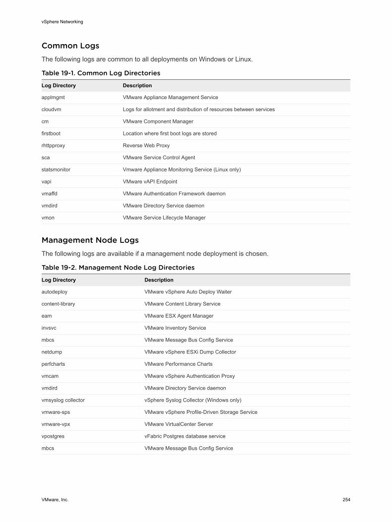
Common LogsThe following logs are common to all deployments on Windows or Linux.
Table 19-1. Common Log Directories
Log Directory Description
applmgmt VMware Appliance Management Service
cloudvm Logs for allotment and distribution of resources between services
cm VMware Component Manager
firstboot Location where first boot logs are stored
rhttpproxy Reverse Web Proxy
sca VMware Service Control Agent
statsmonitor Vmware Appliance Monitoring Service (Linux only)
vapi VMware vAPI Endpoint
vmaffd VMware Authentication Framework daemon
vmdird VMware Directory Service daemon
vmon VMware Service Lifecycle Manager
Management Node LogsThe following logs are available if a management node deployment is chosen.
Table 19-2. Management Node Log Directories
Log Directory Description
autodeploy VMware vSphere Auto Deploy Waiter
content-library VMware Content Library Service
eam VMware ESX Agent Manager
invsvc VMware Inventory Service
mbcs VMware Message Bus Config Service
netdump VMware vSphere ESXi Dump Collector
perfcharts VMware Performance Charts
vmcam VMware vSphere Authentication Proxy
vmdird VMware Directory Service daemon
vmsyslog collector vSphere Syslog Collector (Windows only)
vmware-sps VMware vSphere Profile-Driven Storage Service
vmware-vpx VMware VirtualCenter Server
vpostgres vFabric Postgres database service
mbcs VMware Message Bus Config Service
vSphere Networking
VMware, Inc. 254
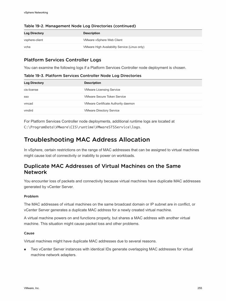
Table 19-2. Management Node Log Directories (continued)
Log Directory Description
vsphere-client VMware vSphere Web Client
vcha VMware High Availability Service (Linux only)
Platform Services Controller LogsYou can examine the following logs if a Platform Services Controller node deployment is chosen.
Table 19-3. Platform Services Controller Node Log Directories
Log Directory Description
cis-license VMware Licensing Service
sso VMware Secure Token Service
vmcad VMware Certificate Authority daemon
vmdird VMware Directory Service
For Platform Services Controller node deployments, additional runtime logs are located at C:\ProgramData\VMware\CIS\runtime\VMwareSTSService\logs.
Troubleshooting MAC Address AllocationIn vSphere, certain restrictions on the range of MAC addresses that can be assigned to virtual machines might cause lost of connectivity or inability to power on workloads.
Duplicate MAC Addresses of Virtual Machines on the Same NetworkYou encounter loss of packets and connectivity because virtual machines have duplicate MAC addresses generated by vCenter Server.
Problem
The MAC addresses of virtual machines on the same broadcast domain or IP subnet are in conflict, or vCenter Server generates a duplicate MAC address for a newly created virtual machine.
A virtual machine powers on and functions properly, but shares a MAC address with another virtual machine. This situation might cause packet loss and other problems.
Cause
Virtual machines might have duplicate MAC addresses due to several reasons.
n Two vCenter Server instances with identical IDs generate overlapping MAC addresses for virtual machine network adapters.
vSphere Networking
VMware, Inc. 255
Each vCenter Server instance has an ID between 0 and 63 that is randomly generated at installation time, but can be reconfigured after installation. vCenter Server uses the instance ID to generate MAC addresses for the network adapters of the machine.
n A virtual machine has been transferred in power-off state from one vCenter Server instance to another in the same network, for example, by using shared storage, and a new virtual machine network adapter on the first vCenter Server receives the freed MAC address.
Solution
u Change the MAC address of a virtual machine network adapter manually.
If you have an existing virtual machine with a conflicting MAC address, you must provide a unique MAC address in the Virtual Hardware settings.
n Power off the virtual machine, configure the adapter to use a manual MAC address, and type the new address.
n If you cannot power the virtual machine off for configuration, re-create the network adapter that is in conflict with enabled manual MAC address assignment and type the new address. In the guest operating system, set the same static IP address to the re-added adapter as before.
For information about configuring the network adapters of virtual machines, see the vSphere Networking and vSphere Virtual Machine Administration documentation.
u If the vCenter Server instance generates the MAC addresses of virtual machines according to the default allocation, VMware OUI, change the vCenter Server instance ID or use another allocation method to resolve conflicts.
Note Changing the vCenter Server instance ID or switching to a different allocation scheme does not resolve MAC address conflicts in existing virtual machines. Only virtual machines created or network adapters added after the change receive addresses according to the new scheme.
vSphere Networking
VMware, Inc. 256
For information about MAC address allocation schemes and setup, see the vSphere Networking documentation.
Solution Description
Change the vCenter Server ID You can keep using the VMware OUI allocation scheme if your deployment contains a small number of vCenter Server instances. According to this scheme, a MAC address has the following format:
00:50:56:XX:YY:ZZ
where 00:50:56 represents the VMware OUI, XX is calculated as (80 + vCenter Server ID), and YY:ZZ is a random number.
To change the vCenter Server ID, configure the vCenter Server unique ID option in the Runtime Settings section from the General settings of the vCenter Server instance and restart it.
The VMware OUI allocation works with up to 64 vCenter Server instances and is suitable for small scale deployments.
Switch to prefix-based allocation You can use a custom OUI. For example, for a 02:12:34 locally administered address range, MAC addresses have the form 02:12:34:XX:YY:ZZ. You can use the fourth octet XX to distribute the OUI address space between the vCenter Server instances. This structure results in 255 address clusters, each cluster managed by a vCenter Server instance, and in about 65000 MAC addresses per vCenter Server. For example, 02:12:34:01:YY:ZZ for vCenter Server A, 02:12:34:02:YY:ZZ for vCenter Server B, and so on.
Prefix-based allocation is suitable for deployments of a larger scale.
For globally unique MAC addresses, the OUI must be registered in IEEE. a Configure MAC address allocation.
b Apply the new MAC address allocation scheme to an existing virtual machine in its Virtual Hardware settings.
n Power off a virtual machine, configure the adapter to use a manual MAC address, revert to automatic MAC address allocation, and power on the virtual machine.
n If the virtual machine is in production and you cannot power it off for configuration, after you change the vCenter Server ID or the address allocation scheme, re-create the network adapter in conflict with enabled automatic MAC address assignment. In the guest operating system, set the same static IP address to the re-added adapter as before.
vSphere Networking
VMware, Inc. 257
u Enforce MAC address regeneration when transferring a virtual machine between vCenter Server instances by using the virtual machine files from a datastore.
a Power off a virtual machine, remove it from the inventory, and in its configuration file (.vmx), set the ethernetX.addressType parameter to generated.
X next to ethernet stands for the sequence number of the virtual NIC in the virtual machine.
b Import the virtual machine from one vCenter Server system to another by registering the virtual machine from a datastore in the target vCenter Server.
The virtual machine files can reside in a datastore that is shared between the two vCenter Server instances or can be uploaded to a datastore that is accessible only from the target vCenter Server system.
For information about registering a virtual machine from a datastore, see vSphere Virtual Machine Administration.
c Power on the virtual machines for the first time.
While the virtual machine is starting up, an information icon appears on the virtual machine in the vSphere Web Client.
d Right-click the virtual machine and select Guest OS > Answer Question.
e Select the I Copied It option.
The target vCenter Server re-generates the MAC address of the virtual machine. The new MAC address starts with the VMware OUI 00:0c:29 and is based on the BIOS UUID of the virtual machine. The BIOS UUID of the virtual machine is calculated from the BIOS UUID of the host.
u If the vCenter Server and hosts are version 6.0 and later and the vCenter Server instances are connected in Enhanced Linked Mode, migrate virtual machines by using vMotion across vCenter Server systems.
When a virtual machine is migrated across vCenter Server systems, the source vCenter Server adds the MAC address of the virtual machine to a blacklist and does not assign them to other virtual machines.
Attempt to Power On a Virtual Machine Fails Due to a MAC Address ConflictAfter you set a certain static MAC address to a virtual machine adapter, you cannot power on the virtual machine.
Problem
In the vSphere Web Client, after you assign a MAC address within the range 00:50:56:40:YY:ZZ – 00:50:56:7F:YY:ZZ to a virtual machine, attempts to power the virtual machine on fail with a status message that the MAC address is in conflict.
00:50:56:XX:YY:ZZ is not a valid static Ethernet address. It
conflicts with VMware reserved MACs for other usage.
vSphere Networking
VMware, Inc. 258
Cause
You attempt to assign a MAC address which starts with the VMware OUI 00:50:56 and is within the address range allocated for host VMkernel adapters on the vCenter Server system.
Solution
If you want to preserve the VMware OUI prefix, set a static MAC address within the range 00:50:56:00:00:00 – 00:50:56:3F:FF:FF. Otherwise, set an arbitrary MAC address whose prefix is different from the VMware OUI one. For information about the ranges available for static MAC addresses that have the VMware OUI prefix, see the vSphere Networking documentation.
Unable to Remove a Host from a vSphere Distributed SwitchUnder certain conditions, you might be unable to remove a host from the vSphere distributed switch.
Problem
n Attempts to remove a host from a vSphere distributed switch fail, and you receive a notification that resources are still in use. The notification that you receive might look like the following:
The resource '16' is in use.
vDS DSwitch port 16 is still on host 10.23.112.2 connected to MyVM nic=4000 type=vmVnic
n Attempts to remove a host proxy switch that still exists on the host from a previous networking configuration fail. For example, you moved the host to a different data center or vCenter Server system, or upgraded the ESXi and vCenter Server software, and created new networking configuration. When trying to remove the host proxy switch, the operation fails because resources on the proxy switch are still in use.
Cause
You cannot remove the host from the distributed switch or delete the host proxy switch because of the following reasons.
n There are VMkernel adapters on the switch that are in use.
n There are virtual machine network adapters connected to the switch.
vSphere Networking
VMware, Inc. 259
Solution
Problem Solution
Cannot remove a host from a distributed switch
1 In the vSphere Web Client, navigate to the distributed switch.
2 On the Configure tab, select More > Ports.
3 Locate all ports that are still in use and check which VMkernel or virtual machine network adapters on the host are still attached to the ports.
4 Migrate or delete the VMkernel and virtual machine network adapters that are still connected to the switch.
5 Use the Add and Manage Hosts wizard in the vSphere Web Client to remove the host from the switch.
After the host is removed, the host proxy switch is deleted automatically.
Cannot remove a host proxy switch
1 In the vSphere Web Client, navigate to the host.
2 Delete or migrate any VMkernel or virtual machine network adapters that are still connected to the host proxy switch.
3 Delete the host proxy switch from the Networking view on the host.
Hosts on a vSphere Distributed Switch Lose Connectivity to vCenter ServerHosts on a vSphere Distributed Switch cannot connect to vCenter Server after a port group configuration.
Problem
After you change the networking configuration of a port group on a vSphere Distributed Switch that contains the VMkernel adapters for the management network, the hosts on the switch lose connectivity to vCenter Server. In the vSphere Web Client the status of the hosts is nonresponsive.
Cause
On a vSphere Distributed Switch in vCenter Server that has networking rollback disabled, the port group containing the VMkernel adapters for the management network is misconfigured in vCenter Server and the invalid configuration is propagated to the hosts on the switch.
Note In vSphere networking rollback is enabled by default. However, you can enable or disable rollbacks at the vCenter Server level. For more information see the vSphere Networking documentation.
Solution
1 From the Direct Console User Interface (DCUI) to an affected host, use the Restore vDS option from the Network Restore Options menu to configure the uplinks and the ID of the VLAN for the management network.
The DCUI creates a local ephemeral port and applies the VLAN and uplink configuration to the port. The DCUI changes the VMkernel adapter for the management network to use the new host local port to restore connectivity to vCenter Server.
vSphere Networking
VMware, Inc. 260
After the host re-connects to vCenter Server, the vSphere Web Client displays a warning that some hosts on the switch have different networking configuration from the configuration stored in vSphere distributed switch.
2 In the vSphere Web Client, configure the distributed port group for the management network with correct settings.
Situation Solution
You have altered the port group configuration only once
You can roll the configuration of the port group back one step. Right-click the port group, click Restore Configuration, and select Restore to previous configuration.
You have backed up a valid configuration of the port group
You can restore the configuration of the port group by using the backup file. Right-click the port group, click Restore Configuration, and select Restore configuration from a file.
You can also restore the configuration for the entire switch, including the port group, from a backup file for the switch.
You have performed more than one configuration step and you do not have a backup file
You must provide valid settings for the port group manually.
For information about networking rollback, recovery, and restore, see the vSphere Networking documentation.
3 Migrate the VMkernel adapter for the management network from the host local ephemeral port to a distributed port on the switch by using the Add and Manage Hosts wizard.
Unlike distributed ports, the ephemeral local port of the VMKernel has a non-numeric ID.
For information about handling VMkernel adapters through the Add and Manage Hosts wizard, see the vSphere Networking documentation.
4 Apply the configuration of the distributed port group and VMkernel adapter from vCenter Server to the host.
n Push the correct configuration of the distributed port group and VMkernel adapter from vCenter Server to the host.
a In the vSphere Web Client, navigate to the host.
b On the Configure tab, click Networking.
c From the Virtual switches list, select the distributed switch and click Rectify the state of the selected distributed switch on the host.
n Wait until vCenter Server applies the settings within the next 24 hours.
Hosts on vSphere Distributed Switch 5.0 and Earlier Lose Connectivity to vCenter ServerHosts on a vSphere Distributed Switch 5.0 and earlier cannot connect to vCenter Server after a port group configuration.
vSphere Networking
VMware, Inc. 261
Problem
After you change the networking configuration of a port group on a vSphere Distributed Switch 5.0 or earlier that contains the VMkernel adapters for the management network, the hosts on the switch lose connectivity to vCenter Server. In the vSphere Web Client the status of the hosts is nonresponsive.
Cause
On a vSphere Distributed Switch 5.0 and earlier in vCenter Server, the port group containing the VMkernel adapters for the management network is misconfigured in vCenter Server and the invalid configuration is propagated to the hosts on the switch.
Solution
1 Connect to an affected host by using the vSphere Client.
2 Under Configuration, select Networking.
3 In the vSphere Standard Switch view, create a new standard switch if the host does not have a standard switch suitable for the management network.
a Click Add Networking.
b In the Add Network wizard, under Connection Types select Virtual Machine, and click Next.
c Select Create a vSphere standard switch.
d Under the Create a vSphere standard switch section, select one or more unoccupied physical adapters on the host to carry the management traffic and click Next.
If all physical adapters are already busy with traffic from other switches, create the switch without a physical network adapter connected. Later, remove the physical adapter for the management network from the proxy switch of the distributed switch and add it to this standard switch.
e In the Port Group Properties section, type a network label that identifies the port group that you are creating and optionally a VLAN ID.
f Click Finish.
4 In the vSphere Distributed Switch view, migrate the VMkernel adapter for the network to a standard switch.
a Select the vSphere Distributed Switch view, and for the distributed switch, click Manage Virtual Adapters.
b In the Manage Virtual Adapters wizard, select the VMkernel adapter from the list and click Migrate.
c Select the newly created or another standard switch to migrate the adapter to, and click Next.
d Enter a network label that is unique in the scope of the host and optionally a VLAN ID for the management network, and click Next.
e Review the settings on the target standard switch and click Finish.
vSphere Networking
VMware, Inc. 262
5 In the vSphere Web Client, configure the distributed port group for the management network with correct settings.
6 Migrate the VMkernel adapter for the management network from the standard switch to a port on the distributed switch by using the Add and Manage Hosts wizard.
For information about the Add and Manage Hosts wizard, see the vSphere Networking documentation.
7 If you have moved the physical adapter from the proxy switch to the standard switch, you can reattach it to the distributed switch again by using the Add and Manage Hosts wizard.
Alarm for Loss of Network Redundancy on a HostAn alarm reports a loss of uplink redundancy on a vSphere standard or a distributed switch for a host.
Problem
No redundant physical NICs for a host are connected to a particular standard or a distributed switch, and the following alarm appears:
Host name or IP Network uplink redundancy lost
Cause
Only one physical NIC on the host is connected to a certain standard or a distributed switch. The redundant physical NICs are either down or are not assigned to the switch.
For example, assume that a host in your environment has physical NICs vmnic0 and vmnic1 connected to vSwitch0, and the physical NIC vmnic1 goes offline, leaving only vmnic0 connected to vSwitch0. As a result, the uplink redundancy for vSwitch0 is lost on the host.
Solution
Check which switch has lost uplink redundancy on the host. Connect at least one more physical NIC on the host to this switch and reset the alarm to green. You can use the vSphere Web Client or the ESXi Shell.
If a physical NIC is down, try to bring it back up by using the ESXi Shell on the host.
For information about using the networking commands in the ESXi Shell, see vSphere Command-Line Interface Reference. For information about configuring networking on a host in the vSphere Web Client, see vSphere Networking.
Virtual Machines Lose Connectivity After Changing the Uplink Failover Order of a Distributed Port GroupChanges in the failover NIC order on a distributed port group cause the virtual machines associated with the group to disconnect from the external network.
vSphere Networking
VMware, Inc. 263
Problem
After you rearrange the uplinks in the failover groups for a distributed port group in vCenter Server, for example, by using the vSphere Web Client, some virtual machines in the port group can no longer access the external network.
Cause
After changing the failover order, many reasons might cause virtual machines to lose connectivity to the external network.
n The host that runs the virtual machines does not have physical NICs associated with the uplinks that are set to active or standby. All uplinks that are associated with physical NICs from the host for the port group are moved to unused.
n A Link Aggregation Group (LAG) that has no physical NICs from the host is set as the only active uplink according to the requirements for using LACP in vSphere.
n If the virtual machine traffic is separated in VLANs, the host physical adapters for the active uplinks might be connected to trunk ports on the physical switch that do not handle traffic from these VLANs.
n If the port group is configured with IP hash load balancing policy, an active uplink adapter is connected to a physical switch port that might not be in an EtherChannel.
You can examine the connectivity of the virtual machines in the port group to associated host uplinks and uplink adapters from the central topology diagram of the distributed switch or from the proxy switch diagram for the host.
Solution
u Restore the failover order with the uplink that is associated with a single physical NIC on the host back to active.
u Create a port group with identical settings, make it use the valid uplink number for the host, and migrate the virtual machine networking to the port group.
u Move the NIC to an uplink that participates in the active failover group.
You can use the vSphere Web Client to move the host physical NIC to another uplink.
n Use the Add and Manage Hosts wizard on the distributed switch.
a Navigate to the distributed switch in the vSphere Web Client.
b From the Actions menu select Add and Manage Hosts.
c On the Select task page, select the Manage host networking option and select the host.
d To assign the NIC of the host to an active uplink, navigate to the Manage physical network adapters page and associate the NIC to the switch uplink.
n Move the NIC at the level of the host.
a Navigate to the host in the vSphere Web Client, and on the Configure tab, expand the Networking menu.
vSphere Networking
VMware, Inc. 264
b Select Virtual Switches and select the distributed proxy switch.
c Click Manage the physical network adapters connected to the selected switch, and move the NIC to the active uplink
Unable to Add a Physical Adapter to a vSphere Distributed Switch That Has Network I/O Control EnabledYou might be unable to add a physical adapter with low speed, for example, 1 Gbps, to a vSphere Distributed Switch that has vSphere Network I/O Control version 3 configured.
Problem
You try to add a physical adapter with low speed, for example, 1 Gbps, to a vSphere Distributed Switch that is connected to physical adapters with high speed, for example, 10 Gbps. Network I/O Control version 3 is enabled on the switch and bandwidth reservations exist for one or more system traffic types, such as vSphere management traffic, vSphere vMotion traffic, vSphere NFS traffic, and so on. The task for adding the physical adapter fails with a status message that a parameter is incorrect.
A specified parameter was not correct: spec.host[].backing.pnicSpec[]
Cause
Network I/O Control aligns the bandwidth that is available for reservation to the 10-Gbps speed of the individual physical adapters that are already connected to the distributed switch. After you reserve a part of this bandwidth, adding a physical adapter whose speed is less than 10 Gbps might not meet the potential needs of a system traffic type.
For information about Network I/O Control version 3, see the vSphere Networking documentation.
Solution
1 In the vSphere Web Client, navigate to the host.
2 On the Configure tab, expand the System group of settings.
3 Select Advanced System Settings and click Edit.
4 Type the physical adapters that you want to use outside the scope of Network I/O Control as a comma-separated list for the Net.IOControlPnicOptOut parameter.
For example: vmnic2,vmnic3
5 Click OK to apply the changes.
6 In the vSphere Web Client, add the physical adapter to the distributed switch.
Troubleshooting SR-IOV Enabled WorkloadsUnder certain conditions, you might experience connectivity or power-on problems with virtual machines that use SR-IOV to send data to physical network adapters.
vSphere Networking
VMware, Inc. 265
SR-IOV Enabled Workload Cannot Communicate After You Change Its MAC AddressAfter you change the MAC address in the guest operating system of an SR-IOV enabled virtual machine, the virtual machine loses connectivity.
Problem
When you connect the network adapter of a virtual machine to an SR-IOV virtual function (VF), you create a passthrough network adapter for the virtual machine. After the (VF) driver in the guest operating system modifies the MAC address for the passthrough network adapter, the guest operating system shows that the change is successful but the VM network adapter loses connectivity. Although the guest operating system shows that the new MAC address is enabled, a log message in the /var/log/vmkernel.log file indicates that the operation has failed.
Requested mac address change to new MAC address on port VM NIC port number, disallowed by vswitch
policy.
where
n new MAC address is the MAC address in the guest operation system.
n VM NIC port number is the port number of the VM network adapter in hexadecimal format.
Cause
The default security policy on the port group to which the passthrough network adapter is connected does not allow changes in the MAC address in the guest operating system. As a result, the networking interface in the guest operating system cannot acquire an IP address and loses connectivity.
Solution
u In the guest operating system, reset the interface to cause the passthrough network adapter to regain its valid MAC address. If the interface is configured to use DHCP for address assignment, the interface acquires an IP address automatically.
For example, on a Linux virtual machine run the ifconfig console command.
ifconfig ethX down
ifconfig ethX up
where X in ethX represents the sequence number of the virtual machine network adapter in the guest operating system.
vSphere Networking
VMware, Inc. 266
A Virtual Machine that Runs a VPN Client Causes Denial of Service for Virtual Machines on the Host or Across a vSphere HA ClusterA virtual machine sending Bridge Protocol Data Unit (BPDU) frames, for example, a VPN client, causes some virtual machines connected to the same port group to lose connectivity. The transmission of BPDU frames might also break the connection of the host or of the parent vSphere HA cluster.
Problem
A virtual machine that is expected to send BPDU frames causes the traffic to the external network of the virtual machines in the same port group to be blocked.
If the virtual machine runs on a host that is a part of a vSphere HA cluster, and the host becomes network-isolated under certain conditions, you observe Denial of Service (DoS) on the hosts in the cluster.
Cause
As a best practice, a physical switch port that is connected to an ESXi host has the Port Fast and BPDU guard enabled to enforce the boundary of the Spanning Tree Protocol (STP). A standard or distributed switch does not support STP, and it does not send any BPDU frames to the switch port. However, if any BPDU frame from a compromised virtual machine arrives at a physical switch port facing an ESXi host , the BPDU guard feature disables the port to stop the frames from affecting the Spanning Tree Topology of the network.
In certain cases a virtual machine is expected to send BPDU frames, for example, when deploying VPN that is connected through a Windows bridge device or through a bridge function. If the physical switch port paired with the physical adapter that handles the traffic from this virtual machine has the BPDU guard on, the port is error-disabled, and the virtual machines and VMkernel adapters using the host physical adapter cannot communicate with the external network anymore.
If the teaming and failover policy of the port group contains more active uplinks, the BPDU traffic is moved to the adapter for the next active uplink. The new physical switch port becomes disabled, and more workloads become unable to exchange packets with the network. Eventually, almost all entities on the ESXi host might become unreachable.
If the virtual machine runs on a host that is a part of a vSphere HA cluster, and the host becomes network-isolated because most of the physical switch ports connected to it are disabled, the active master host in the cluster moves the BPDU sender virtual machine to another host. The virtual machine starts disabling the physical switch ports connected to the new host. The migration across the vSphere HA cluster eventually leads to accumulated DoS across the entire cluster.
vSphere Networking
VMware, Inc. 267
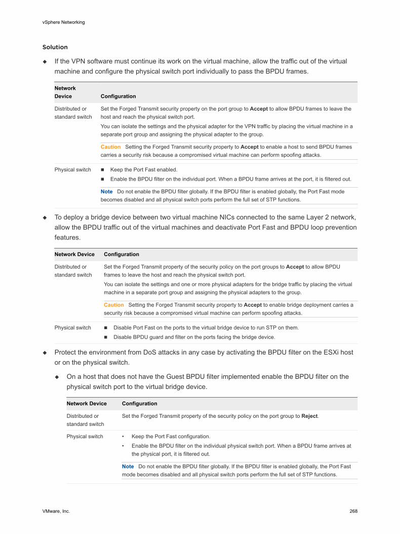
Solution
u If the VPN software must continue its work on the virtual machine, allow the traffic out of the virtual machine and configure the physical switch port individually to pass the BPDU frames.
Network Device Configuration
Distributed or standard switch
Set the Forged Transmit security property on the port group to Accept to allow BPDU frames to leave the host and reach the physical switch port.
You can isolate the settings and the physical adapter for the VPN traffic by placing the virtual machine in a separate port group and assigning the physical adapter to the group.
Caution Setting the Forged Transmit security property to Accept to enable a host to send BPDU frames carries a security risk because a compromised virtual machine can perform spoofing attacks.
Physical switch n Keep the Port Fast enabled.
n Enable the BPDU filter on the individual port. When a BPDU frame arrives at the port, it is filtered out.
Note Do not enable the BPDU filter globally. If the BPDU filter is enabled globally, the Port Fast mode becomes disabled and all physical switch ports perform the full set of STP functions.
u To deploy a bridge device between two virtual machine NICs connected to the same Layer 2 network, allow the BPDU traffic out of the virtual machines and deactivate Port Fast and BPDU loop prevention features.
Network Device Configuration
Distributed or standard switch
Set the Forged Transmit property of the security policy on the port groups to Accept to allow BPDU frames to leave the host and reach the physical switch port.
You can isolate the settings and one or more physical adapters for the bridge traffic by placing the virtual machine in a separate port group and assigning the physical adapters to the group.
Caution Setting the Forged Transmit security property to Accept to enable bridge deployment carries a security risk because a compromised virtual machine can perform spoofing attacks.
Physical switch n Disable Port Fast on the ports to the virtual bridge device to run STP on them.
n Disable BPDU guard and filter on the ports facing the bridge device.
u Protect the environment from DoS attacks in any case by activating the BPDU filter on the ESXi host or on the physical switch.
u On a host that does not have the Guest BPDU filter implemented enable the BPDU filter on the physical switch port to the virtual bridge device.
Network Device Configuration
Distributed or standard switch
Set the Forged Transmit property of the security policy on the port group to Reject.
Physical switch • Keep the Port Fast configuration.
• Enable the BPDU filter on the individual physical switch port. When a BPDU frame arrives at the physical port, it is filtered out.
Note Do not enable the BPDU filter globally. If the BPDU filter is enabled globally, the Port Fast mode becomes disabled and all physical switch ports perform the full set of STP functions.
vSphere Networking
VMware, Inc. 268
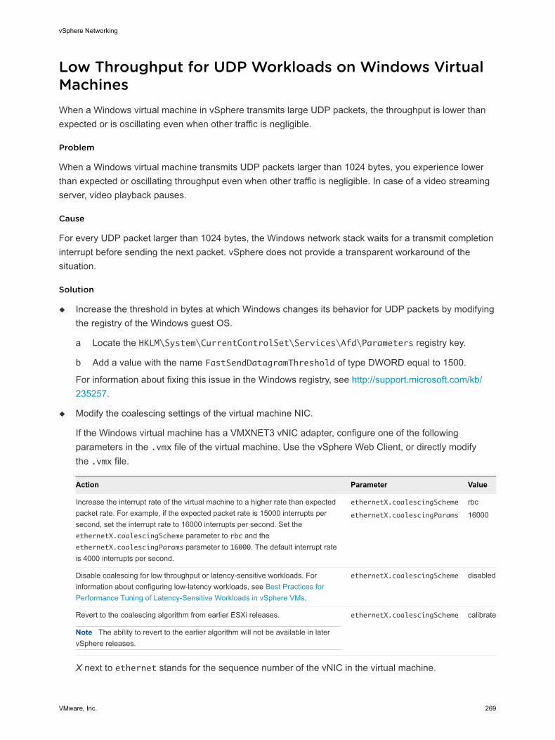
Low Throughput for UDP Workloads on Windows Virtual MachinesWhen a Windows virtual machine in vSphere transmits large UDP packets, the throughput is lower than expected or is oscillating even when other traffic is negligible.
Problem
When a Windows virtual machine transmits UDP packets larger than 1024 bytes, you experience lower than expected or oscillating throughput even when other traffic is negligible. In case of a video streaming server, video playback pauses.
Cause
For every UDP packet larger than 1024 bytes, the Windows network stack waits for a transmit completion interrupt before sending the next packet. vSphere does not provide a transparent workaround of the situation.
Solution
u Increase the threshold in bytes at which Windows changes its behavior for UDP packets by modifying the registry of the Windows guest OS.
a Locate the HKLM\System\CurrentControlSet\Services\Afd\Parameters registry key.
b Add a value with the name FastSendDatagramThreshold of type DWORD equal to 1500.
For information about fixing this issue in the Windows registry, see http://support.microsoft.com/kb/235257.
u Modify the coalescing settings of the virtual machine NIC.
If the Windows virtual machine has a VMXNET3 vNIC adapter, configure one of the following parameters in the .vmx file of the virtual machine. Use the vSphere Web Client, or directly modify the .vmx file.
Action Parameter Value
Increase the interrupt rate of the virtual machine to a higher rate than expected packet rate. For example, if the expected packet rate is 15000 interrupts per second, set the interrupt rate to 16000 interrupts per second. Set the ethernetX.coalescingScheme parameter to rbc and the ethernetX.coalescingParams parameter to 16000. The default interrupt rate is 4000 interrupts per second.
ethernetX.coalescingScheme
ethernetX.coalescingParams
rbc
16000
Disable coalescing for low throughput or latency-sensitive workloads. For information about configuring low-latency workloads, see Best Practices for Performance Tuning of Latency-Sensitive Workloads in vSphere VMs.
ethernetX.coalescingScheme disabled
Revert to the coalescing algorithm from earlier ESXi releases.
Note The ability to revert to the earlier algorithm will not be available in later vSphere releases.
ethernetX.coalescingScheme calibrate
X next to ethernet stands for the sequence number of the vNIC in the virtual machine.
vSphere Networking
VMware, Inc. 269
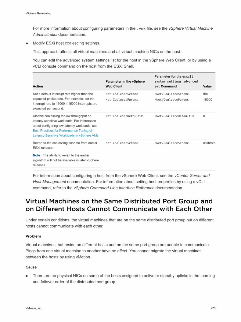
For more information about configuring parameters in the .vmx file, see the vSphere Virtual Machine Administrationdocumentation.
u Modify ESXi host coalescing settings.
This approach affects all virtual machines and all virtual machine NICs on the host.
You can edit the advanced system settings list for the host in the vSphere Web Client, or by using a vCLI console command on the host from the ESXi Shell.
ActionParameter in the vSphere Web Client
Parameter for the esxcli system settings sdvanced
set Command Value
Set a default interrupt rate higher than the expected packet rate. For example, set the interrupt rate to 16000 if 15000 interrupts are expected per second.
Net.CoalesceScheme
Net.CoalesceParams
/Net/CoalesceScheme
/Net/CoalesceParams
rbc
16000
Disable coalescing for low throughput or latency-sensitive workloads. For information about configuring low-latency workloads, see Best Practices for Performance Tuning of Latency-Sensitive Workloads in vSphere VMs.
Net.CoalesceDefaultOn /Net/CoalesceDefaultOn 0
Revert to the coalescing scheme from earlier ESXi releases.
Note The ability to revert to the earlier algorithm will not be available in later vSphere releases.
Net.CoalesceScheme /Net/CoalesceScheme calibrate
For information about configuring a host from the vSphere Web Client, see the vCenter Server and Host Management documentation. For information about setting host properties by using a vCLI command, refer to the vSphere Command-Line Interface Reference documentation.
Virtual Machines on the Same Distributed Port Group and on Different Hosts Cannot Communicate with Each OtherUnder certain conditions, the virtual machines that are on the same distributed port group but on different hosts cannot communicate with each other.
Problem
Virtual machines that reside on different hosts and on the same port group are unable to communicate. Pings from one virtual machine to another have no effect. You cannot migrate the virtual machines between the hosts by using vMotion.
Cause
n There are no physical NICs on some of the hosts assigned to active or standby uplinks in the teaming and failover order of the distributed port group.
vSphere Networking
VMware, Inc. 270
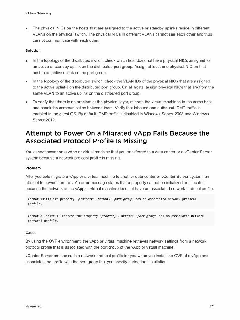
n The physical NICs on the hosts that are assigned to the active or standby uplinks reside in different VLANs on the physical switch. The physical NICs in different VLANs cannot see each other and thus cannot communicate with each other.
Solution
n In the topology of the distributed switch, check which host does not have physical NICs assigned to an active or standby uplink on the distributed port group. Assign at least one physical NIC on that host to an active uplink on the port group.
n In the topology of the distributed switch, check the VLAN IDs of the physical NICs that are assigned to the active uplinks on the distributed port group. On all hosts, assign physical NICs that are from the same VLAN to an active uplink on the distributed port group.
n To verify that there is no problem at the physical layer, migrate the virtual machines to the same host and check the communication between them. Verify that inbound and outbound ICMP traffic is enabled in the guest OS. By default ICMP traffic is disabled in Windows Server 2008 and Windows Server 2012.
Attempt to Power On a Migrated vApp Fails Because the Associated Protocol Profile Is MissingYou cannot power on a vApp or virtual machine that you transferred to a data center or a vCenter Server system because a network protocol profile is missing.
Problem
After you cold migrate a vApp or a virtual machine to another data center or vCenter Server system, an attempt to power it on fails. An error message states that a property cannot be initialized or allocated because the network of the vApp or virtual machine does not have an associated network protocol profile.
Cannot initialize property 'property'. Network 'port group' has no associated network protocol
profile.
Cannot allocate IP address for property 'property'. Network 'port group' has no associated network
protocol profile.
Cause
By using the OVF environment, the vApp or virtual machine retrieves network settings from a network protocol profile that is associated with the port group of the vApp or virtual machine.
vCenter Server creates such a network protocol profile for you when you install the OVF of a vApp and associates the profile with the port group that you specify during the installation.
vSphere Networking
VMware, Inc. 271
The mapping between the protocol profile and port group is valid only in the scope of a data center. When you move the vApp, the protocol profile is not transferred to the target data center because of the following reasons:
n The network settings of the protocol profile might not be valid in the network environment of the target data center.
n A port group that has the same name and is associated with another protocol profile might already exist in the target data center, and vApps and virtual machines might be connected to this group. Replacing the protocol profiles for the port group might affect the connectivity of these vApp and virtual machines.
Solution
n Create a network protocol profile on the target data center or vCenter Server system with the required network settings and associate the protocol profile with the port group to which the vApp or virtual machine is connected. For example, this approach is suitable if the vApp or virtual machine is a vCenter Server extension that uses the vCenter Extension vService.
For information about providing network settings to a vApp or virtual machine from a network protocol profile, see the vSphere Networking documentation.
n Use the vSphere Web Client to export the OVF file of the vApp or virtual machine from the source data center or vCenter Server system and deploy it on the target data center or vCenter Server system.
When you use the vSphere Web Client to deploy the OVF file, the target vCenter Server system creates the network protocol profile for the vApp.
For information about managing OVF files in the vSphere Web Client, see the vSphere Virtual Machine Administration documentation.
Networking Configuration Operation Is Rolled Back and a Host Is Disconnected from vCenter ServerWhen you attempt to add or configure networking on a vSphere Distributed Switch on a host, the operation is rolled back and the host is disconnected from vCenter Server.
Problem
An attempt to perform a networking configuration operation on a vSphere Distributed Switch on a host, such as creating a virtual machine adapter or a port group, causes the host to disconnect from vCenter Server and results in the error message Transaction has rolled back on the host.
Cause
Under stressful conditions on a host, that is, if many concurrent networking operations compete for limited resources, the time to perform some of the operations might exceed the default timeout for rollback of network configuration operations on the distributed switch. As a result, these operations are rolled back.
vSphere Networking
VMware, Inc. 272
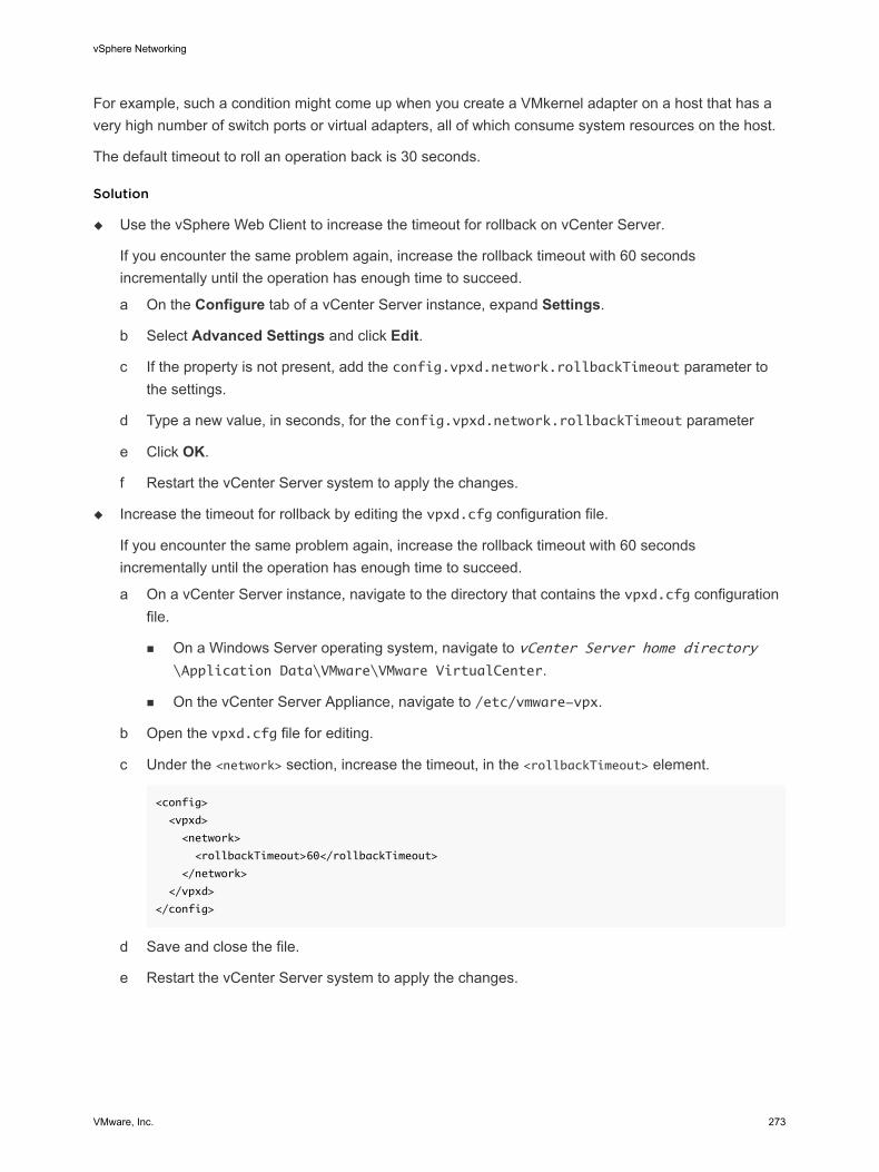
For example, such a condition might come up when you create a VMkernel adapter on a host that has a very high number of switch ports or virtual adapters, all of which consume system resources on the host.
The default timeout to roll an operation back is 30 seconds.
Solution
u Use the vSphere Web Client to increase the timeout for rollback on vCenter Server.
If you encounter the same problem again, increase the rollback timeout with 60 seconds incrementally until the operation has enough time to succeed.
a On the Configure tab of a vCenter Server instance, expand Settings.
b Select Advanced Settings and click Edit.
c If the property is not present, add the config.vpxd.network.rollbackTimeout parameter to the settings.
d Type a new value, in seconds, for the config.vpxd.network.rollbackTimeout parameter
e Click OK.
f Restart the vCenter Server system to apply the changes.
u Increase the timeout for rollback by editing the vpxd.cfg configuration file.
If you encounter the same problem again, increase the rollback timeout with 60 seconds incrementally until the operation has enough time to succeed.
a On a vCenter Server instance, navigate to the directory that contains the vpxd.cfg configuration file.
n On a Windows Server operating system, navigate to vCenter Server home directory\Application Data\VMware\VMware VirtualCenter.
n On the vCenter Server Appliance, navigate to /etc/vmware-vpx.
b Open the vpxd.cfg file for editing.
c Under the <network> section, increase the timeout, in the <rollbackTimeout> element.
<config>
<vpxd>
<network>
<rollbackTimeout>60</rollbackTimeout>
</network>
</vpxd>
</config>
d Save and close the file.
e Restart the vCenter Server system to apply the changes.
vSphere Networking
VMware, Inc. 273

![VMware vSphere: Install, Configure, Manage [V6] 2021. 2. 5. · Students install and/or run client software on these desktops, including vSphere Client, vSphere Web Client, vSphere](https://img.pdfslide.tips/doc/110x75/6101f8db0e13ad30ab174d7c/vmware-vsphere-install-configure-manage-v6-2021-2-5-students-install-andor.jpg)