Embed Size (px)
Citation preview
12 / 2013 87
X-ENP
C
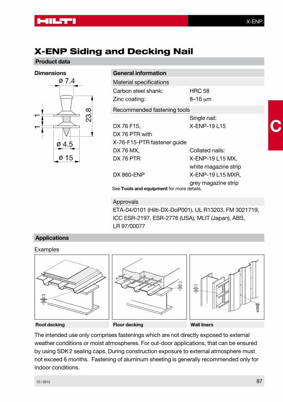
X-ENP Siding and Decking Nail
General information
Material specifications
Carbon steel shank: HRC 58Zinc coating: 8–16 μm
Recommended fastening tools Single nail:DX 76 F15, X-ENP-19 L15DX 76 PTR with X-76-F15-PTR fastener guideDX 76 MX, Collated nails:DX 76 PTR X-ENP-19 L15 MX, white magazine stripDX 860-ENP X-ENP-19 L15 MXR, grey magazine stripSee Tools and equipment for more details.
ApprovalsETA-04/0101 (Hilti-DX-DoP001), UL R13203, FM 3021719, ICC ESR-2197, ESR-2776 (USA), MLIT (Japan), ABS, LR 97/00077
Dimensions
Examples
Product data
Applications
Roof decking Floor decking Wall liners
The intended use only comprises fastenings which are not directly exposed to external weather conditions or moist atmospheres. For out-door applications, that can be ensured by using SDK 2 sealing caps. During construction exposure to external atmosphere must not exceed 6 months. Fastening of aluminum sheeting is generally recommended only for indoor conditions.
X-ENP
88 12 / 2013
C
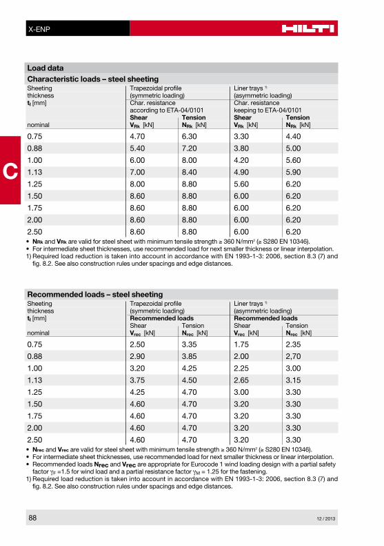
Load dataCharacteristic loads – steel sheetingSheeting Trapezoidal profile Liner trays 1)
thickness (symmetric loading) (asymmetric loading)tI [mm] Char. resistance Char. resistance according to ETA-04/0101 keeping to ETA-04/0101 Shear Tension Shear Tensionnominal VRk [kN] NRk [kN] VRk [kN] NRk [kN]
0.75 4.70 6.30 3.30 4.40
0.88 5.40 7.20 3.80 5.00
1.00 6.00 8.00 4.20 5.60
1.13 7.00 8.40 4.90 5.90
1.25 8.00 8.80 5.60 6.20
1.50 8.60 8.80 6.00 6.20
1.75 8.60 8.80 6.00 6.20
2.00 8.60 8.80 6.00 6.20
2.50 8.60 8.80 6.00 6.20• NRk and VRk are valid for steel sheet with minimum tensile strength ≥ 360 N/mm2 (≥ S280 EN 10346).• For intermediate sheet thicknesses, use recommended load for next smaller thickness or linear interpolation.1) Required load reduction is taken into account in accordance with EN 1993-1-3: 2006, section 8.3 (7) and
fig. 8.2. See also construction rules under spacings and edge distances.
Recommended loads – steel sheetingSheeting Trapezoidal profile Liner trays 1)
thickness (symmetric loading) (asymmetric loading)tI [mm] Recommended loads Recommended loads Shear Tension Shear Tensionnominal Vrec [kN] Nrec [kN] Vrec [kN] Nrec [kN]
0.75 2.50 3.35 1.75 2.35
0.88 2.90 3.85 2.00 2,70
1.00 3.20 4.25 2.25 3.00
1.13 3.75 4.50 2.65 3.15
1.25 4.25 4.70 3.00 3.30
1.50 4.60 4.70 3.20 3.30
1.75 4.60 4.70 3.20 3.30
2.00 4.60 4.70 3.20 3.30
2.50 4.60 4.70 3.20 3.30• Nrec and Vrec are valid for steel sheet with minimum tensile strength ≥ 360 N/mm2 (≥ S280 EN 10346).• For intermediate sheet thicknesses, use recommended load for next smaller thickness or linear interpolation.• Recommended loads Nrec and Vrec are appropriate for Eurocode 1 wind loading design with a partial safety
factor γF =1.5 for wind load and a partial resistance factor γM = 1.25 for the fastening.1) Required load reduction is taken into account in accordance with EN 1993-1-3: 2006, section 8.3 (7) and
fig. 8.2. See also construction rules under spacings and edge distances.
12 / 2013 89
X-ENP
C
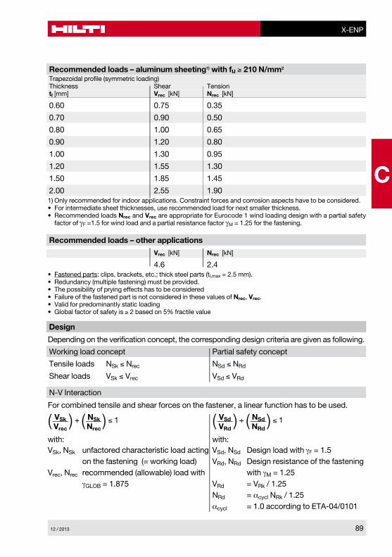
Recommended loads – aluminum sheeting1) with fu ≥ 210 N/mm2
Trapezoidal profile (symmetric loading)Thickness Shear TensiontI [mm] Vrec [kN] Nrec [kN]
0.60 0.75 0.35
0.70 0.90 0.50
0.80 1.00 0.65
0.90 1.20 0.80
1.00 1.30 0.95
1.20 1.55 1.30
1.50 1.85 1.45
2.00 2.55 1.901) Only recommended for indoor applications. Constraint forces and corrosion aspects have to be considered.• For intermediate sheet thicknesses, use recommended load for next smaller thickness.• Recommended loads Nrec and Vrec are appropriate for Eurocode 1 wind loading design with a partial safety
factor of γF =1.5 for wind load and a partial resistance factor γM = 1.25 for the fastening.
Recommended loads – other applications
Vrec [kN] Nrec [kN]
4.6 2.4• Fastened parts: clips, brackets, etc.; thick steel parts (tl,max = 2.5 mm).• Redundancy (multiple fastening) must be provided.• The possibility of prying effects has to be considered• Failure of the fastened part is not considered in these values of Nrec, Vrec.• Valid for predominantly static loading• Global factor of safety is ≥ 2 based on 5% fractile value
Design
Depending on the verification concept, the corresponding design criteria are given as following.
Working load concept Partial safety concept
Tensile loads NSk ≤ Nrec NSd ≤ NRd
Shear loads VSk ≤ Vrec VSd ≤ VRd
N-V Interaction
For combined tensile and shear forces on the fastener, a linear function has to be used.
( VSkVrec
) + (NSkNrec
) ≤ 1 ( VSdVRd
) + (NSdNRd
) ≤ 1
VSk, NSk unfactored characteristic load acting VSd, NSd Design load with γF = 1.5 on the fastening (= working load) VRd, NRd Design resistance of the fasteningVrec, Nrec recommended (allowable) load with with γM = 1.25 γGLOB = 1.875 VRd = VRk / 1.25 NRd = αcycl NRk / 1.25 αcycl = 1.0 according to ETA-04/0101
with: with:

X-ENP
90 12 / 2013
C
Thickness of base material
Application requirements
t IISteel thickness tII
Thickness of fastened material
Sheet thicknesses and overlap types
Σtl, tot ≤ 4.0 mm
(a)single
(b)side lap
(c)end overlap
(d)side lap and end overlap
Nominal sheeting thickness tI [mm] Allowable overlap types
0.63–1.00 a, b, c, d
> 1.00–1.25 a, c
> 1.25–2.50 aWith the above recommended sheet thickness and overlap types, it is not necessary to take into account the effect of constraints due to temperature for steel grades up to S320 (EN 10346). For steel grade S350 (EN 10346) it shall be considered for design. Sheets of grade S350 on base material tII ≥ 8 mm have been verified by Hilti, forces of constraint can be neglected.
tII ≥ 6 mm
12 / 2013 91
X-ENP
C
Corrosion information
The intended use only comprises fastenings which are not directly exposed to external weather conditions or moist atmospheres. For outdoor applications that can be ensured by using SDK2 sealing caps. During construction exposure to external atmosphere must not exceed 6 Month. Fastening of Aluminum sheeting is generally recommended only for indoor conditions.
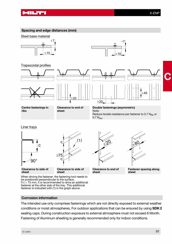
Spacing and edge distances (mm)
7
15
7
10
Steel base material
Trapezoidal profiles
2020
45
Centre fastenings in ribs
Clearance to end of sheet
Double fastenings (asymmetric)Note: Reduce tensile resistance per fastener to 0.7 NRk or 0.7 Nrec.
Liner trays
c
90°75
(1)c
c
20 80
Clearance to side of sheet
Clearance to side of sheet
Clearance to end of sheet
Fastener spacing along sheet
When driving the fastener, the fastening tool needs to be positioned perpendicular to the surface. If c > 75 mm, it is recommended to drive an additional fastener at the other side of the tray. This additional fastener is indicated with (1) in the graph above.

X-ENP
92 12 / 2013
C
6350 400 450 500 550 600 650 700 750
7
8
9
10
11
12
13
14
15
16
17
18
10
20
21
22
Ste
el th
ickn
ess
t II [m
m]
Steel strength Rm [N/mm2]
Applicablerange of base
materials
S 235
S 275
S 355
X-ENP-19 with DX 76, DX 76 PTR and DX 860-ENP
Application limit
Fastener selection and system recommendation
Fasteners Tools Fastener guide Designation Item no. Designation Designation
Single nail: X-ENP-19 L15 283506 DX 76 PTR X-76-F15-PTR DX 76 F15
Collated nails: X-ENP-19 L15 MX, 283507 DX 76 PTR white magazine strip DX 76 MX X-ENP-19 L15 MXR, 283508 DX 860-ENP grey magazine strip
Piston: X-76-P-ENP-PTR DX 76 PTR X-76-P-ENP DX 76 DX 860-ENP

12 / 2013 93
X-ENP
C
Fine adjustment by installation tests on site.Note for S275: Start with recommendation for S355. In case of too much energy: reduction of tool energy setting or change of cartridge colour till correct nail head stand-offs hNVS are achieved.
Cartridge selection and tool energy setting
DX 76, DX 860-ENP DX 76 PTR
6
7
8
9
10
11
12
13
14
15
16
17
18
19
>20
Ste
el th
ickn
ess
t II [m
m]
Red 4or
Black 2
Red 3or
Black 1
Blue 4 orRed 2
Blue 3 Red 3
Red 4 orBlack 2
Black 4
Black 3
S 235 S 355 6
7
8
9
10
11
12
13
14
15
16
17
18
19
>20
Ste
el th
ickn
ess
t II [
mm
]
Red 4or
Black 2
Blue 4
orRed 2
Blue 3
orRed 1
Red 3
Red 4
Black 4
S 235 S 355S 275
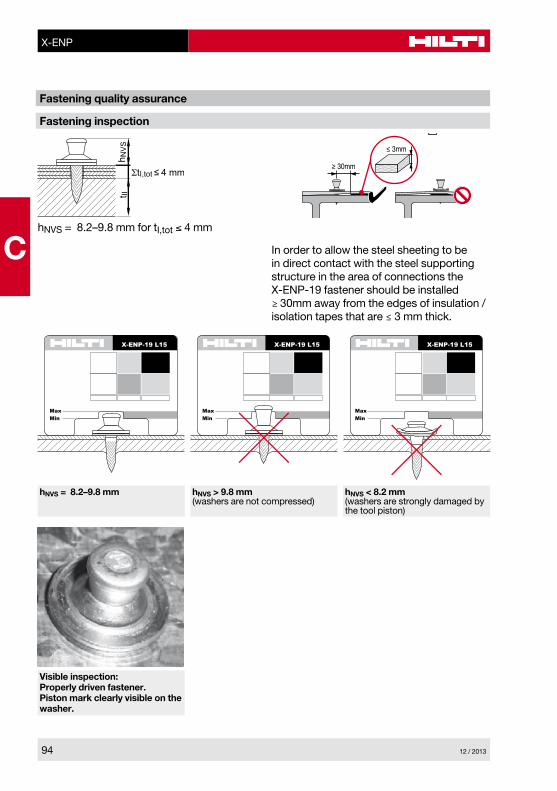
h NV
St II
ΣtI,tot ≤ 4 mm
hNVS = 8.2–9.8 mm for tI,tot ≤ 4 mm
In order to allow the steel sheeting to be in direct contact with the steel supporting structure in the area of connections the X-ENP-19 fastener should be installed ≥ 30mm away from the edges of insulation / isolation tapes that are ≤ 3 mm thick.
Fastening inspection
Fastening quality assurance
X-ENP-19 L15
MaxMin
X-ENP-19 L15
MaxMin
X-ENP-19 L15
MaxMin
hNVS = 8.2–9.8 mm hNVS > 9.8 mm(washers are not compressed)
hNVS < 8.2 mm(washers are strongly damaged by the tool piston)
Visible inspection:Properly driven fastener. Piston mark clearly visible on the washer.
C
94 12 / 2013
X-ENP