Embed Size (px)
DESCRIPTION
M4 journal
Citation preview

1
DIGITAL DESIGN + FABRICATION SM1, 2015 M4 Journal- Plant Support
ZIHAO GUO(683552)
Paul Loh - Tutorial 11am Thursday
2
Front Elevation- Stage1
Back Elevation -Stage 1
Left Elevation- Stage 1
Left Elevation- Stage 1 Sitting Position

3
Introduction
Personal space can be identified when people need to interact with the surrounding environment with or without any other human being. Through the semester, we have completed a second skin project which is able to create personal space. By doing the design processes, we have been taught with lots of digital design skills and fabrication techniques through the weekly lectures, readings and tutorials.
Left Elevation- Stage 2 Standing Position Left Elevation- Stage 3 Standing Position Front Elevation- Stage 3 Standing Position

4
1.0 Ideation

5
My object is a plant support that is able to ex-pand and create a ruled surface. It is formed by couples of timber sticks and using pins to fix the timer sticks together. The complex ruled surface system is based on a fundamen-tal element which is formed by two sticks and one fixing pin between as a cross. With the fundamental element that has been found, the whole structure can be formed with basic polar array. As a result, types of ruled surface will be created by those arrays. I need to measure the length of the sticks by tape ruler and also the minimum and maximum radius of the top and the bottom by using the scale ruler. Furthermore, the degrees between two sticks on the fixing points are also needed in terms of the accurate drawing.
Measured Drawings

6
Reconfigured ModelWith the principle of our plant support which is based on arraying with some fixing points, I am trying to use the same material system into my design including section & profile as well as creating ruled surfaces. Instead of using the same shape of the plant support, I try to reshape the plant support model with twisting and shifting the fixing points in my reconfigured model. In addition, the circular organization of the fixing points has been changed to some rectangular shapes. By doing that, the structure of the model itself still works as an section and profile system and creates another ruled surface.

According to Sommer (1969), ‘“Personal space refers to an area with invisible boundaries surrounding a persons body into whcih intruder may not come.” My sketch designs is going to create the personal space for the human upper body when people are interacting with others.
7
Sketch Design #1
Fear ; Offensive& Defensive
Back to the reconfigured model, I found that the structure can be spilt into two parts which are able to be worn on the upper body. The design is going to provide more personal space and allow some movements.
8
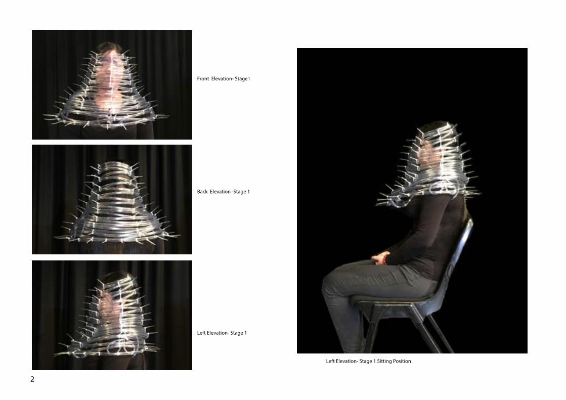
Fear ; Offensive& Defensive
This design is base on the shape of triangle and lots of acute angles which might provide a sense of fear, anxious and offensive to others and a sense of safe to the user at the same time as it work like a shield sleeve. That might help improve the user’s personal space with the interaction with others.
Sketch Design #2

9
Sketch Design #3
Mass ; Protection; Defensive
The design with solid volume attach to the body create a personal space in three dimension. It also provides a sense of defensive and protection which might make people feel comfortable and relax with the surrounding space.

10
2.0 DesignZihao Guo & Siyun Yang
11
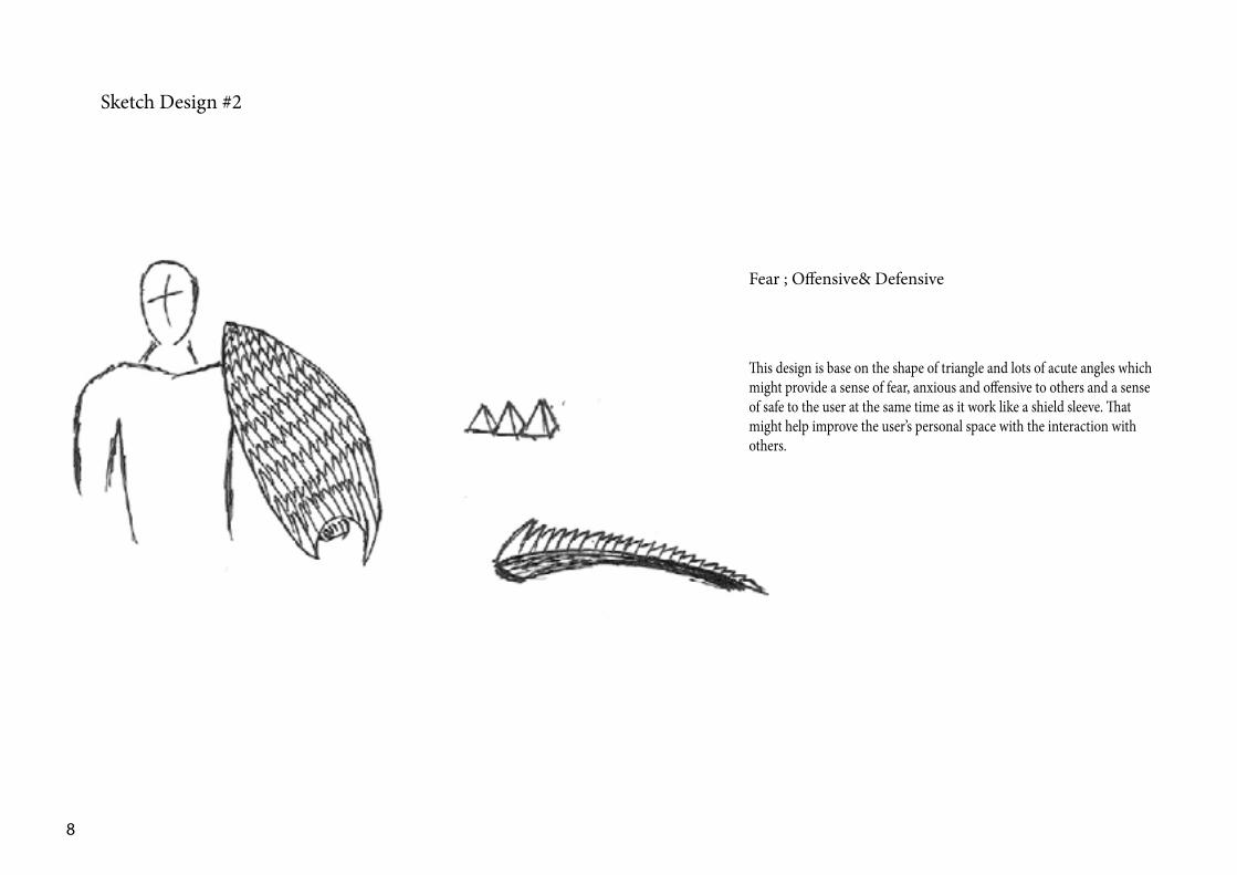
In terms of making a second skin design that is able to create personal space, the dimensions of our personal space are necessary for the project. Thus, Si measured her own personal space in various situations as our sec-ond skin project is going to sit on her body. With the measurement of her personal space, we can get some ideas of the size of our design and how it is related to the personal space.

12
Design Development Introduction
Moving from the ideation to the design processes, some kinds of accurate digital models are needed instead of those abstract sketches. The design need to be more relevant to the human body and focus on the personal space rather than the system itself on the ideation processes. However, the idea of sectioning as well as ruled surface have been taken forward to this stage. I try to use a series of sectioning to form a structure in my second skin project and create personal space.

13
Design Proposal V. 1
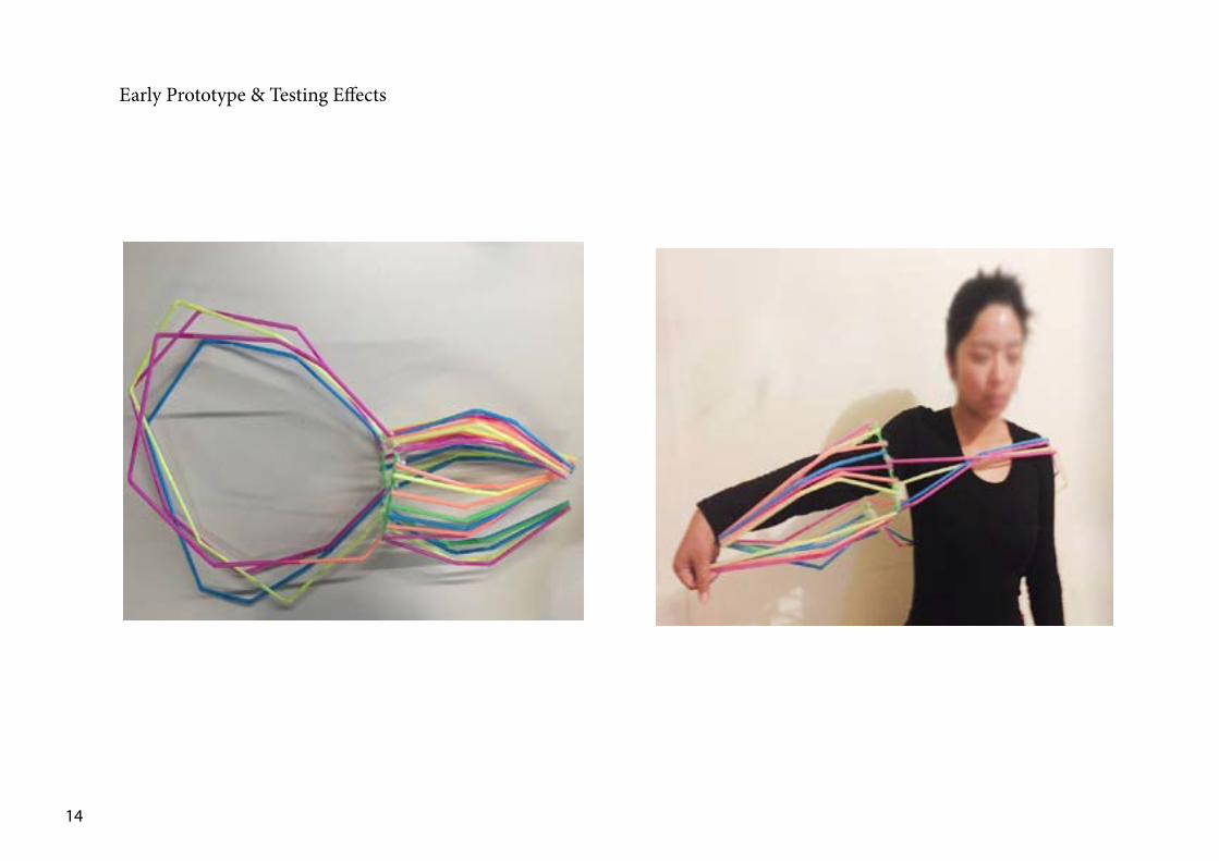
When we try to refine our design, we found the original sketch design is not flexible enough and the uses can not adjust their personal space when they are in different situation and with dif-ferent people. In addition , the structure can be in more organic curve shapes than before which will make the design more con-tinuous. Our design is going to create a personal space around our arm and upper body. The structure is consisted of a series of sectioning lines which are able to create a ruled surface.
14
Early Prototype & Testing Effects

15
Design Proposal V. 2
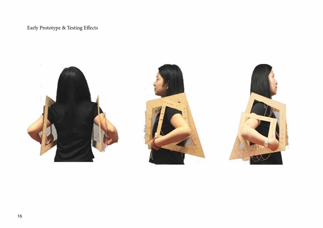
In terms of personal space, it represents the area around the human body. Personal space can be various in different scenario with different groups of people. Our design is basically trying to create a second skin which is based on the same structure like the plant support and provide personal space. The second skin is designed for particular scenario when the users need to move their arms frequently and avoid intercepting with other people around by creating more personal space. Therefore, the skin second skin can be used when they are working on the library or other study area where they might want to be get-ting isolated. However, either the previous design or this design is not a completed or successful project as it does not demonstrate that much relationships between the personal space and the structure of the design. The shape and the structure of the design are not quite convincing in terms of personal space. They seem to be randomly picked and designed as a second skin project. Therefore , we moved to the design proposal version three which is more convincing as it has been developed on the other way..
16
Early Prototype & Testing Effects

17
Precedent Studies
Skin & Contouring
The design and the idea of the Drop by Olivia Decaris inspire me a lot in the relationship between our design and the personal space. As we are using sectioning and contouring techniques in our project, we need to know where are those sectioning and contour-ing lines from. This is a good example as the paper skin might be the personal space and the contouring lines can become the main structure of the design.
The Drop by Olivia Decaris
http://www.dezeen.com/2009/06/29/the-drop-series-by-olivia-decaris/
Fluid Shape & Continuous Connections
The Burnham Pavilion by Zaha Hadid is based on a skin and bone structure. Its bent-alumium structure created an unique curvilinear form For its ‘bone’, they are made by a series planner sectioning. And those sectioning lines are connected with crossing and continuous connection for supporting the whole structure.
Burnham Pavilion by Zaha Hadid Architect
http://www.dezeen.com/2009/08/24/burnham-pavilion-by-zaha-hadid-architects-2/

18
Design Proposal V. 3
By doing more precedent studies and thinking back to the personal space, we decided to take our personal space area as a starting point to go with. We created a surface that represents the personal space area first on the digital model by offsetting the human body mesh with the accurate dimension that we measured. Then we got a series of curves by sectioning and contouring of the personal space surface. Besides , those sectioning and contouring might need to be intercepted each other with fixing points to make the structure hold itself.

19
Design Proposal V. 3
Perspective view on body

3.0 FabricationZihao Guo & Siyun Yang
20
21
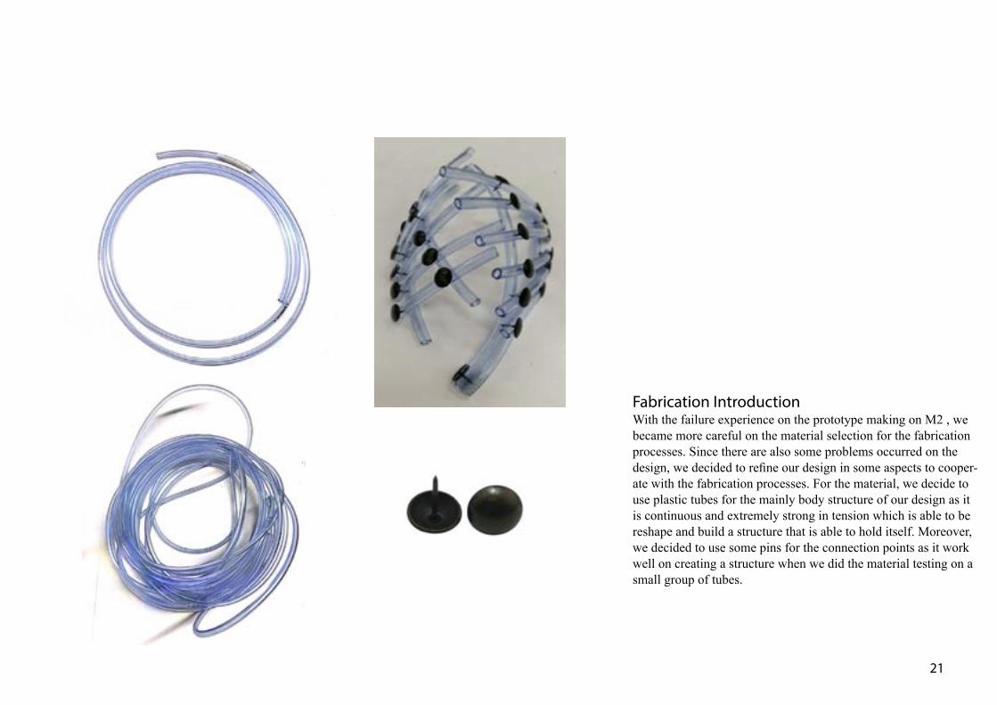
Fabrication IntroductionWith the failure experience on the prototype making on M2 , we became more careful on the material selection for the fabrication processes. Since there are also some problems occurred on the design, we decided to refine our design in some aspects to cooper-ate with the fabrication processes. For the material, we decide to use plastic tubes for the mainly body structure of our design as it is continuous and extremely strong in tension which is able to be reshape and build a structure that is able to hold itself. Moreover, we decided to use some pins for the connection points as it work well on creating a structure when we did the material testing on a small group of tubes.

22
Refer to Kolarevic(2003)’s reading, we decided to create a structure that is able to be held by the planar sec-tion components themselves by crossing each other and form ‘grids’ . In order to get the planar sections of the structure, we firstly built a mesh or surface for our personal space area which we measured. After that, we used the contouring tool and sectioning tool to get the planar section from the personal space’s surface. Some of those sections might need to be intercepted each other to create a structure that is able to hold itself with those structural members. However, we found lots of problems took place on the prototype fabrication process. The pins are not strong enough to fix a large group of tubes. Apart from it, the upper overhanging tubes are not successfully supported by the horizontal section below as they are two heavy with their self weight. Therefore some optimization is needed for the project. According to Iwamoto(2009), We need to keep doing the pro-cesses of design and fabrication in a loop to refine our design.. We kept doing our prototype by referring to the digital model from getting fixing points and dimension for the tubes. At the same time, we got some feedback from the material property to the digital model.
Fabrication of Prototype V. 2
23
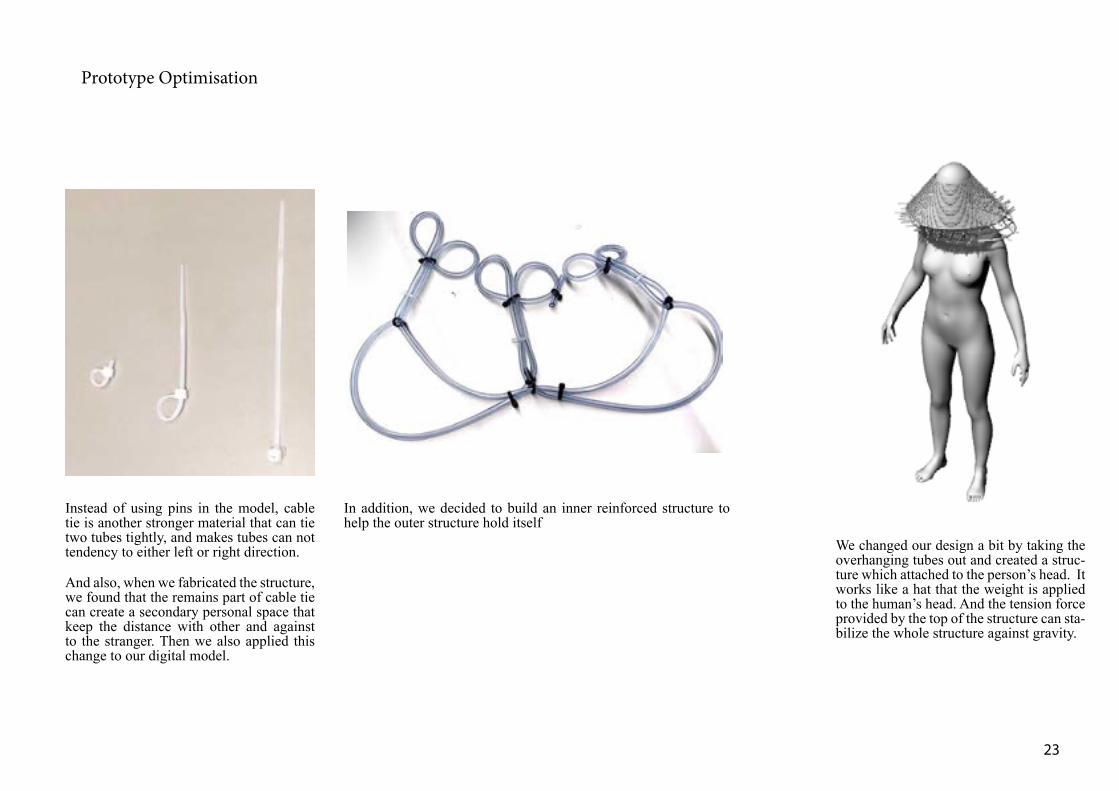
Prototype Optimisation
Instead of using pins in the model, cable tie is another stronger material that can tie two tubes tightly, and makes tubes can not tendency to either left or right direction.
And also, when we fabricated the structure, we found that the remains part of cable tie can create a secondary personal space that keep the distance with other and against to the stranger. Then we also applied this change to our digital model.
In addition, we decided to build an inner reinforced structure to help the outer structure hold itself
We changed our design a bit by taking the overhanging tubes out and created a struc-ture which attached to the person’s head. It works like a hat that the weight is applied to the human’s head. And the tension force provided by the top of the structure can sta-bilize the whole structure against gravity.

24
In order to get connection between the human’s head and the chest which suppose to be showing the personal space , we borrow the idea from the Robyn’s dynamic out-fit. On its design a series of continuous tubes have been connected together in same plane. With the structure of its design, the material which is the plastic tube can hold itself and perform extremely strong against either tension or compression. Therefore we tied our 20 meters long con-tinuous tube up into the shape above with cable ties.
Robyn’s Dynamic Outfit
http://www.designboom.com:8080/technology/lucy-mcrae-fluid-textiles-in-robyn-video/

25
Final Prototype Digital Model
Right Elevation Front Elevation Perspective View Plan
26
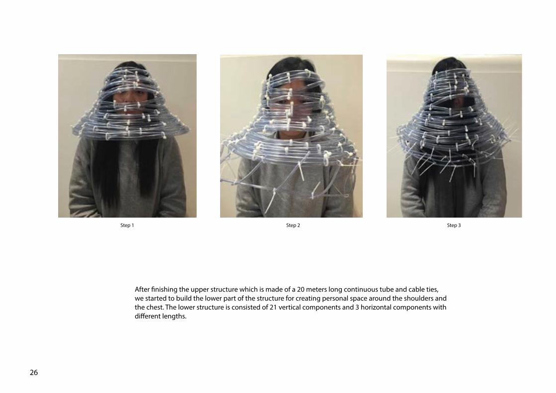
Step 1 Step 2 Step 3
After finishing the upper structure which is made of a 20 meters long continuous tube and cable ties, we started to build the lower part of the structure for creating personal space around the shoulders and the chest. The lower structure is consisted of 21 vertical components and 3 horizontal components with different lengths.

27
Fabrication Sequence
The diagram shows the elements we used in the physical prototype.

28
Assembly Drawing

Prototype by itself Right view: prototype on the body in normal time
Front view: prototype on the body in normal time Back view: prototype on the body in normal time
29

30
4.0 REFLECTION

31
Left Elevation- Stage 1 Sitting Position Left Elevation- Stage 3 Standing PositionLeft Elevation- Stage 2 Standing Position
In the final stage, we refine our prototype a bit and make it more tidy for the final prototype submission. Apart from it, we simplify our design by removing some useless cable ties as well as the lower messy structure. By removing those cable ties, more stretches can be made to the model. With those stretches, our second skin project becomes more adjustable while more movements can be created .The structure can be operated by pull-ing it down by users’ hands. It is able to provide more flexibility to the personal space and suit more situations and sce-narios.

Reflection The readings on M4 is like a summary to the whole subject which talk about the processes through the design, draft and the fabrication. According to the Rifkin (2011). We are very lucky to live with the third industrial revolution which is devel-oped by the internet and digital technology. The relationships between designing and making become more direct. We can get our design printed by the 3d printer or other techniques of fabrication on the campus or even at home. This seem to be a small shift while it actually allow many small business or workshop survive in the market. But back to the second industrial revolution, all the resources and the production are controlled by those monopoly business. For the relation-ships between design and fabrication were far away from each other as you need to get your resources for the design with more processes all the way through the manufactory, wholesalers and retailers. Those processes might cause extra cost and time to the projects. With the development of technology, we are able to optimize our design through the pro-cesses of digital design and fabrication which has been talked about on the M3 readings and also applied to our second skin project . In Deamer & Bernstein’s reading, the idea of risk are also meaningful for the design processes as we all want to avoid the risk at all cost. During the digital design or craft processes, it is able to imagine the risk structurally, aestheti-cally, financially and even emotionally as amounts of information is able to be put in and analyzed by the CNC system.
Through the semester, we have been taught with a lot of digital design techniques including some Rhino skills. But more importantly, we learn how to fabricate our design with the digital assist and how to optimize our design through the fab-rication process. I can still remember what my tutor said to me a building need 18 months to build but four to five years to design. By doing the second skin project, I started to get the idea of what does it mean to the relationships between the design processes and fabrication processes. For me , the M2 journal of our group are the thing that push us forward most. As it let us know the way we proceed in the design processes was wrong. And we started to do more analysis before we do the design. We stopped randomly picking ideas and started thinking about how our design would be moved to fabri-cation process when we are doing the sketch design or digital model.
32

33
5.0 APPENDIX
Bibliography:
Architecture in the Digital Age - Design and Manufacturing /Branko Kolarevic. Spon Press, London, c2003
Building the Future: Recasting Labor in Architecture/ Philip Bernstein, Peggy Deamer. Princeton Architectural Press. c2008. pp 38-42
Burnham Pavilion, Hadid, Z. Retrieved 07/06/2015 from http://www.dezeen.com/2009/08/24/burnham-pavilion-by-zaha-hadid-architects-2/
Digital fabrications: architectural and material techniques / Lisa Iwamoto. New York : Princeton Architectural Press, c2009.
Sommer, R. (1969). Personal space : the behavioral basis of design / Robert Sommer. Englewood Cliffs, N.J. : Prentice-Hall, c1969.
The Drop Series, Decaris, O. Retrieved 07/06/2015 from http://www.dezeen.com/2009/06/29/the-drop-series-by-olivia-decaris/
The third Industrial Revolution / Jeremy Rifkin. Palgrave Macmillan, C2011.pp107-126
Lucy Mcrae, 2010, Retrieved 07/06/2015 from http://www.designboom.com:8080/technology/lucy-mcrae-fluid-textiles-in-robyn-video/

34


![Zebnbd evgu gZ]jZ^u - emddom.ucoz.netemddom.ucoz.net/pedagogi_na_sajt_3.pdf · ^hfZª mq_[guo qZkZ k ] ih 14.09 ] mq_[guo qZkZ m^hklh\_j_gb_ hih\ur_gbb d\ZebnbdZpbb ]](https://img.pdfslide.tips/doc/110x75/5d04fdf288c99327718df2c9/zebnbd-evgu-gzjzu-hfza-mqguo-qzkz-k-ih-1409-mqguo-qzkz-mhklhjgb.jpg)