Mitsubishi Heavy Industries, Ltd.Technical Review Vol. 45 No. 3 (Sep. 2008)
1
Development of Compact a n d H i g h - p e r f o r m a n c e Turbocharger for 1,050°C Exhaust Gas
KOJI MATSUMOTO*1 MASAKI TOJO*1
YASUAKI JINNAI*1 NORIYUKI HAYASHI*1
SEIICHI IBARAKI*2
The control of global exhaust gas emissions and the legislation concerning fuel consumption have promoted the reduction of the size of engines for passenger automobiles, and as a result, the engine output per unit cylinder displacement is increasing. As the turbocharger is an effective way of making high-output engines smaller, the demand for turbochargers is increasing, and technological improvements are required. The exhaust gas temperature of gasoline engines is rising, giving better combustion efficiency, and this requires the timely development of compatible turbochargers. In the face of this global demand, Mitsubishi Heavy Industries, Ltd. (MHI) has developed, and has started delivering to customers, compact and high-performance turbochargers capable of operating at 1,050°C, the world’s highest level of exhaust gas temperature.
1. Introduction
To cope with present environmental restrictions, small displacement engines equipped with a turbocharger are increasingly used in place of naturally aspirated large-displacement engines, while maintaining a similar level of engine output. This so-called “downsizing” trend helps to increase the number of turbochargers required. In the past, turbochargers for gasoline engines were only used on a few models of high-performance sports cars produced in small quantities for a limited number of customers. However, the recent wave of downsizing has prompted turbochargers to be installed on an increasing number of gasoline engines.
The sharp increases in the price of gasoline and the strict control of CO2 emissions (see Fig. 1) are the reasons behind the strong drive for better fuel consumption.1
With the demand for gasoline engine turbochargers is expected to increase, and engine operating conditions are expected to become more severe (e.g., increased exhaust gas temperatures), a turbocharger capable of dealing with high exhaust temperatures is urgently required.
2. Features of turbochargers for gasoline engines
The exhaust gas temperature of a gasoline engine is generally about 200°C higher than that of a diesel engine, and thus requires a more sophist icated turbocharger that can withstand the higher temperature. Exhaust gas temperatures are further increasing to cope with recent emissions restr ict ions and the demand for small but powerful engines. The requirement to handle exhaust gas temperatures as high as 1,050°C has already been identified (see Fig. 2).
*1 General Machinery & Special Vehicle Headquarters*2 Nagasaki Research & Development Center, Technical Headquarters
201 /km
169.8 /km
161 /km
120 /km
127 /km
137.5 /km
: Fuel consumption legislation in the State of California : Japanese fuel consumption in 2015 : Fuel consumption legislation in the European Union
Year
CO
2 em
issi
on (
/km
)
210200190180170160150140130120110100
2000 2005 2010 2015 2020 Year
Exh
aust
tem
per
atur
e (°
C)
1100
1050
1000
950
900
8501995 2000 2005 2010
Fig. 1 Transition of CO2 emission levels regulated by areasFig. 2 Transition of gasoline engine exhaust gas temperature
for MHI’s customers
2
Mitsubishi Heavy Industries, Ltd.Technical Review Vol. 45 No. 3 (Sep. 2008)
In a fuel - injected engine where fuel is injected into the intake port, it is general practice to set the engine compression ratio lower than that of a naturally aspirated engine in order to avoid knocking. However, due to the cooling ef fect of the vaporization heat of the fuel spray that suppresses knocking, the direct-injection engine can maintain a compression ratio comparable to that of the naturally aspirated engine. However, this raises the turbine inlet pressure and increases the load on the turbocharger.2
While the demand for gasoline engine turbochargers is increasing, the functional requirements such as high exhaust gas temperature and pressure require urgent development of a durable turbocharger. The following functions must be evaluated to verify the durability requirements.• Strength of the turbine wheel• Strength of the turbine housing• Optimization of the wastegate valve mechanism
The next section discusses these factors in detail.
3. Technologies to cope with high exhaust temperaturea
3.1 Turbine wheelInconel is a standard material for turbine wheels. This
nickel-based heat-resistant alloy, however, does not meet MHI’s criteria for anti-creep characteristics at 1,050°C, MHI has decided, therefore, to use MarM, a similar nickel-based heat-resistant alloy with greater strength at high temperature. W hile MHI has used MarM for the turbochargers in competition vehicles such as rally cars, this is the f irst t ime that MHI has used MarM in mass-produced vehicles. Since MarM is more difficult to cast and more likely to have minute casting defects than Inconel, MHI uses hot isostatic pressing (HIP) on MarM to remove casting defects and to homogenize the material structure. HIP is a metal treatment technology that uses an inert gas such as argon as a pressurizing medium and utilizes the synergistic effect of a pressure normally greater than 100 MPa and a temperature higher than 1,000°C.
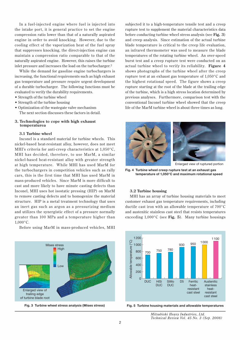
Before using MarM in mass-produced vehicles, MHI
subjected it to a high-temperature tensile test and a creep rupture test to supplement the material characteristics data before conducting turbine wheel stress analysis (see Fig. 3) and creep analysis. Since estimation of the actual turbine blade temperature is critical to the creep life evaluation, an infrared thermometer was used to measure the blade temperatures of the rotating turbine wheel. An over-speed burst test and a creep rupture test were conducted on an actual turbine wheel to verify its reliability. Figure 4 shows photographs of the turbine wheel after the creep rupture test at an exhaust gas temperature of 1,050°C and the highest rotational speed. The figure shows a creep rupture starting at the root of the blade at the trailing edge of the turbine, which is a high stress location determined by previous analyses. Furthermore, comparison test with the conventional Inconel turbine wheel showed that the creep life of the MarM turbine wheel is about three times as long.
3.2 Turbine housing MHI has an array of turbine housing materials to meet
customer exhaust gas temperature requirements, including ductile cast iron with an allowable temperature of 700°C and austenitic stainless cast steel that resists temperatures exceeding 1,000°C (see Fig. 5). Many turbine housings
Fig. 4 Turbine wheel creep rupture test at an exhaust gas temperature of 1,050°C and maximum rotational speed
Mises stressHigh
Low
Enlarged view of trailing edge
of turbine blade root
Enlarged view of ruptured portion
1200
1000
800
600
400
200
0DUC D5 Austenitic
stainlessheat-
resistantcast steel
Ferriticheat-
resistantcast steel
SiMoDUC
HiSiDUC
700 750 780
930 950 10001100
Allo
wab
le t
emp
erat
ure
(°C
)
Fig. 3 Turbine wheel stress analysis (Mises stress) Fig. 5 Turbine housing materials and allowable temperatures

Mitsubishi Heavy Industries, Ltd.Technical Review Vol. 45 No. 3 (Sep. 2008)
3
of recent gasol ine engine turbochargers are made of austenitic stainless cast steel. Optimization of turbine housing profiles is as important as material selection in ensuring the strength at elevated temperatures. The engine operating conditions expose the turbine housings to repeated heating and cooling, making them subject to possible cracking through thermal fatigue. To avoid thermal cracks, MHI conducted an exhaust gas f low analysis (see Fig. 6), a heat transfer analysis between the exhaust gas and the turbine housing, and a turbine housing thermal st ress analysis , a l l under t ransient operat ing condit ions , cor responding to the eng ine operating conditions, to locate the high-stress regions (see Fig. 7). In addition to using austenitic stainless cast steel, eliminating the structural discontinuity from the turbine housing and the use of a more uniform wall thickness helps to prevent the generation of cracks.
3.3 Wastegate valveThe wastegate valve bypasses exhaust gas to control
the air pressure entering the engine. Since the wastegate valve must operate without lubrication while being exposed to an exhaust gas of higher temperature, its resistance to seizure is particularly important.
MHI’s development included a high-temperature wear test of the wastegate valve material on the test bench shown in Fig. 8 to verify its anti-seizure characteristics. The results suggested a combination of materials with anti-seizure characteristics that exceed those of conventional materials (see Fig. 9).
In addit ion, a structural analysis was conducted to optimize the wastegate valve mechanism to reduce the
Flow velocity
Exhaust manifold
Turbine housing
High
Low
Thermal stress
High
Low
(b) Combination ofmaterials used
in actual product
Mild scratchSeizure
(a) Combination of conventional materials
Fig. 7 Example of thermal stress analysis of turbine housing
Fig. 6 Results of flow analysis (flow velocity distribution)
Fig. 8 High-temperature wear test bench
Fig. 9 State of sliding surfaces after high-temperature wear tests

4
Mitsubishi Heavy Industries, Ltd.Technical Review Vol. 45 No. 3 (Sep. 2008)
wear. Figure 10 shows the structural analysis model. Using the dimensions of each member of the mechanism as parameters, the simulation took place while applying variable loads equivalent to the exhaust pulsation to evaluate the severity (slide amount and load) of the sliding section. Figure 11 shows an example of the calculated results. This analysis provided MHI with dimensions that reduced the severity of the wear, and this design was incorporated into the end products.
4. More compact and higher performance
To design a simple engine compartment layout, a compact turbocharger design is required. The demand for compact turbochargers is increasing because of the requirement to shorten the catalytic activation time at engine startup and to reduce the thermal capacity of the exhaust gas passage that reaches the catalyst. Since the catalyst must be hot to be active, it is necessary to reduce the amount of heat absorbed by components on the exhaust gas passage such as the exhaust manifold and turbine housing. To meet this requirement, MHI has been delivering turbochargers in which the exhaust manifold and turbine housing are combined in a single cast part (see Fig. 12). To make the turbocharger even more compact and lightweight, MHI has developed a production method, jointly with a customer, whereby the exhaust manifold is press-formed from a sheet of stainless steel and welded to the cast turbine housing (see
Fig. 13). The exhaust manifold is double-walled, and this greatly reduces its thermal capacity.
5. Conclusion
To meet the requirements of the increasingly stringent legislation on exhaust emission and fuel consumption, MHI has concentrated its ef forts on high-temperature exhaust gas turbochargers for gasoline engines. MHI has
Sev
erity
of
wea
r ge
nera
tion
Small Medium Large
Dimension A
Small Medium Large
Dimension B
Small Medium Large
Dimension C
Small Medium Large
Dimension D
Dimensions for reducing wearMorewear
Lesswear
ValveValve
JointJoint
LeverLever
ShaftShaft
BushBush
Fig. 10 Wastegate valve structural analysis model
Fig. 11 Example of calculation of wear severity by structural analysis
Fig. 13 Turbocharger with unitized exhaust manifold (weld-fabricated structure)
Fig. 12 Turbocharger with unitized exhaust manifold (unitized casting)

Mitsubishi Heavy Industries, Ltd.Technical Review Vol. 45 No. 3 (Sep. 2008)
5
Masaki Tojo Yasuaki JinnaiKoji Matsumoto
Noriyuki Hayashi Seiichi Ibaraki
successfully developed, and has started to deliver, compact high-performance turbochargers capable of dealing with an exhaust gas temperature of 1,050°C, the highest in the world. By conducting further thermal stress analysis and structural analysis of sliding mechanisms to evaluate design before prototyping, MHI is meeting exacting customer needs and reducing development time to deliver better automobile environmental performance and driving pleasure.
References
1. Yoshiro Tsuruhara, Fuel Economy Regulat ions in Europe, Automotive Technology, Vol.1 (2008) p.122
2. Luttermann, C. et al., BMW High Precision Fuel Inject ion Conjunction with Twin-Turbo Technology: a Combination for Maximum Dynamic and High Fuel Ef f iciency, SA E Paper 2007-01-1560
Recommended