中车时代电气功率半导体英国研发中心
TEC Power Semiconductor R&D Centre(UK)
英国 林肯, Lincoln, United Kingdom
Double-sided Cooling Integrated Power Module and Power Control Unit
Dynex Semiconductor
AESIN Conference - October 20th 2016
CONTENT
第一部分 南车株洲所简介
第二部分 电机驱动系统
第三部分 IGBT与组件
COMPANY PROFILE
PART 2 HEV/EV Application
PART 3 Capabilities
PART 1
PART 4 Performance
1. COMPANY PROFILE
3
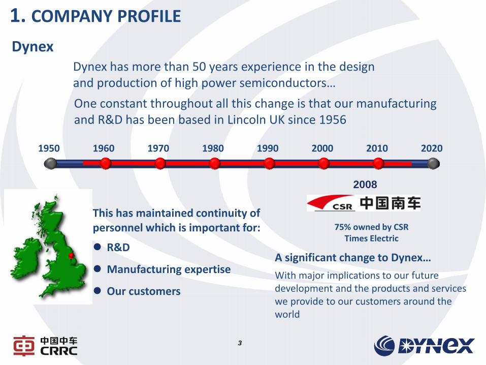
Dynex Dynex has more than 50 years experience in the design and production of high power semiconductors…
One constant throughout all this change is that our manufacturing and R&D has been based in Lincoln UK since 1956
This has maintained continuity of personnel which is important for:
R&D
Manufacturing expertise
Our customers
1950 1960 1970 1980 1990 2000 2010 2020
2008
75% owned by CSR Times Electric
A significant change to Dynex…
With major implications to our future development and the products and services we provide to our customers around the world
1. COMPANY PROFILE
4
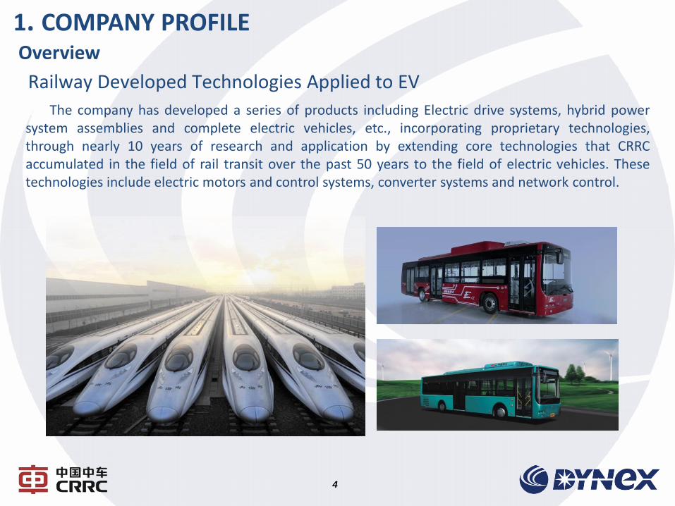
Overview
The company has developed a series of products including Electric drive systems, hybrid power system assemblies and complete electric vehicles, etc., incorporating proprietary technologies, through nearly 10 years of research and application by extending core technologies that CRRC accumulated in the field of rail transit over the past 50 years to the field of electric vehicles. These technologies include electric motors and control systems, converter systems and network control.
Railway Developed Technologies Applied to EV
1. COMPANY PROFILE
5
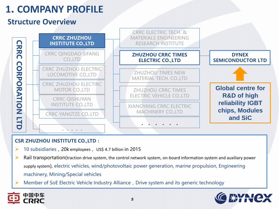
Structure Overview CRRC ELECTRIC TECH. &
MATERIALS ENGINEERING RESEARCH INSTITUTE
ZHUZHOU CRRC TIMES ELECTRIC CO.,LTD
ZHUZHOU TIMES NEW MATERIAL TECH. CO.,LTD
ZHUZHOU CRRC TIMES ELECTRIC VEHICLE CO.,LTD
XIANGYANG CRRC ELECTRIC MACHINERY CO.,LTD
......
CR
RC
CO
RP
OR
AT
ION
LTD
CRRC ZHUZHOU INSTITUTE CO.,LTD
CRRC QINGDAO SIFANG CO.,LTD
CRRC ZHUZHOU ELECTRIC LOCOMOTIVE CO.,LTD
CRRC ZHUZHOU ELECTIRC MOTOR CO.,LTD
CRRC QISHUYAN INSTITUTE CO.,LTD
CRRC YANGTZE CO.,LTD
.....
DYNEX SEMICONDUCTOR LTD
CSR ZHUZHOU INSTITUTE CO.,LTD:
10 subsidiaries,20k employees, US$ 4.7 billion in 2015
Rail transportation(traction drive system, the control network system, on-board information system and auxiliary power
supply system), electric vehicles, wind/photovoltaic power generation, marine propulsion, Engineering
machinery, Mining/Special vehicles
Member of SoE Electric Vehicle Industry Alliance,Drive system and its generic technology
Global centre for
R&D of high
reliability IGBT
chips, Modules
and SiC
CONTENT
第一部分 南车株洲所简介
第二部分 电机驱动系统
第三部分 IGBT与组件
COMPANY PROFILE
PART 2 HEV/EV Application
PART 3 Capabilities
PART 1
PART 4 Performance
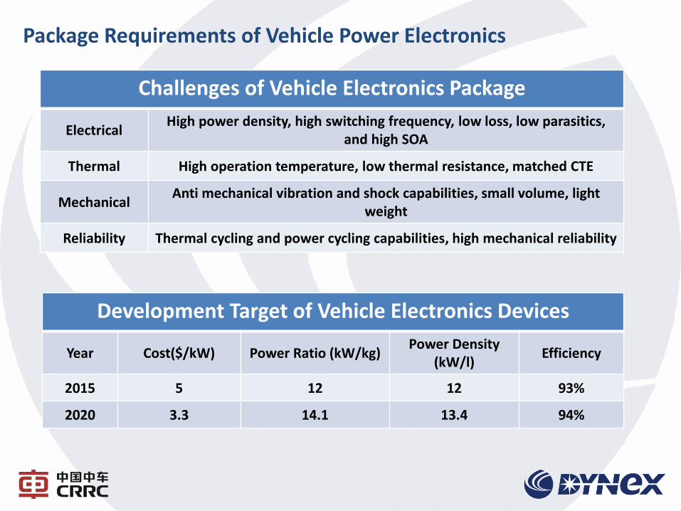
Development Target of Vehicle Electronics Devices
Year Cost($/kW) Power Ratio (kW/kg) Power Density
(kW/l) Efficiency
2015 5 12 12 93%
2020 3.3 14.1 13.4 94%
Challenges of Vehicle Electronics Package
Electrical High power density, high switching frequency, low loss, low parasitics,
and high SOA
Thermal High operation temperature, low thermal resistance, matched CTE
Mechanical Anti mechanical vibration and shock capabilities, small volume, light
weight
Reliability Thermal cycling and power cycling capabilities, high mechanical reliability
Package Requirements of Vehicle Power Electronics
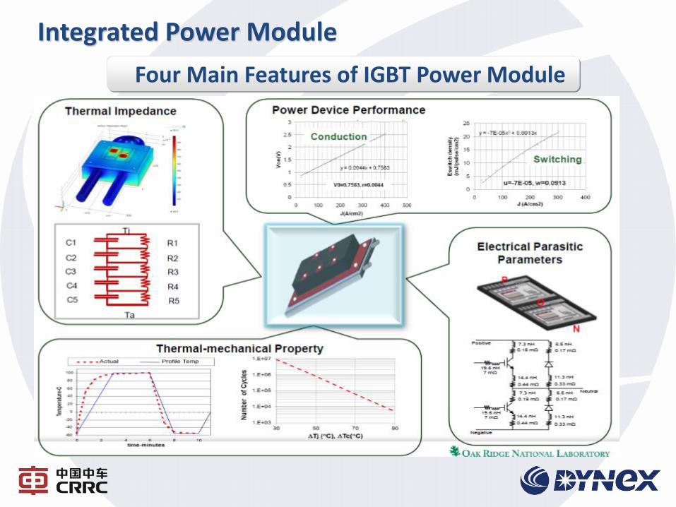
Four Main Features of IGBT Power Module
Integrated Power Module
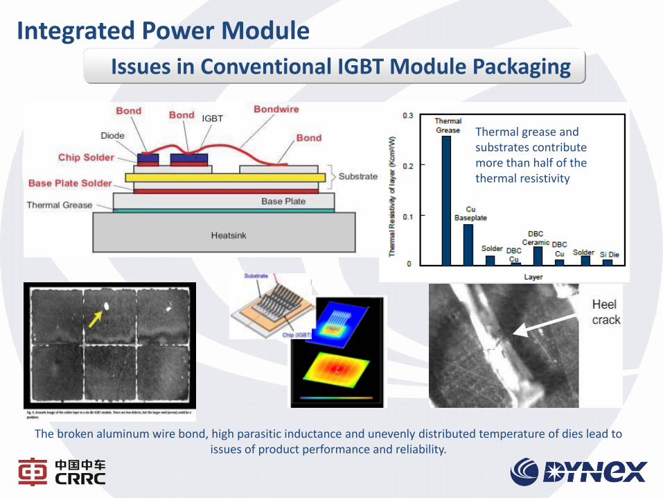
Issues in Conventional IGBT Module Packaging
Thermal grease and substrates contribute more than half of the thermal resistivity
The broken aluminum wire bond, high parasitic inductance and unevenly distributed temperature of dies lead to issues of product performance and reliability.
Integrated Power Module
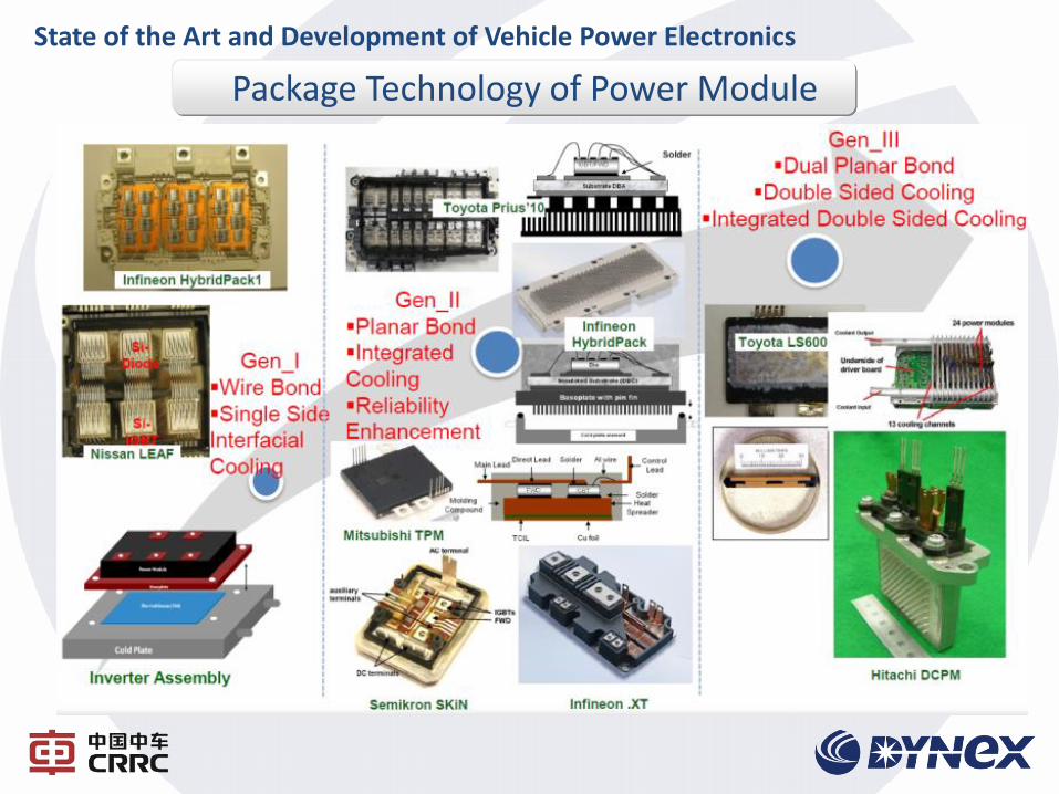
Package Technology of Power Module
State of the Art and Development of Vehicle Power Electronics
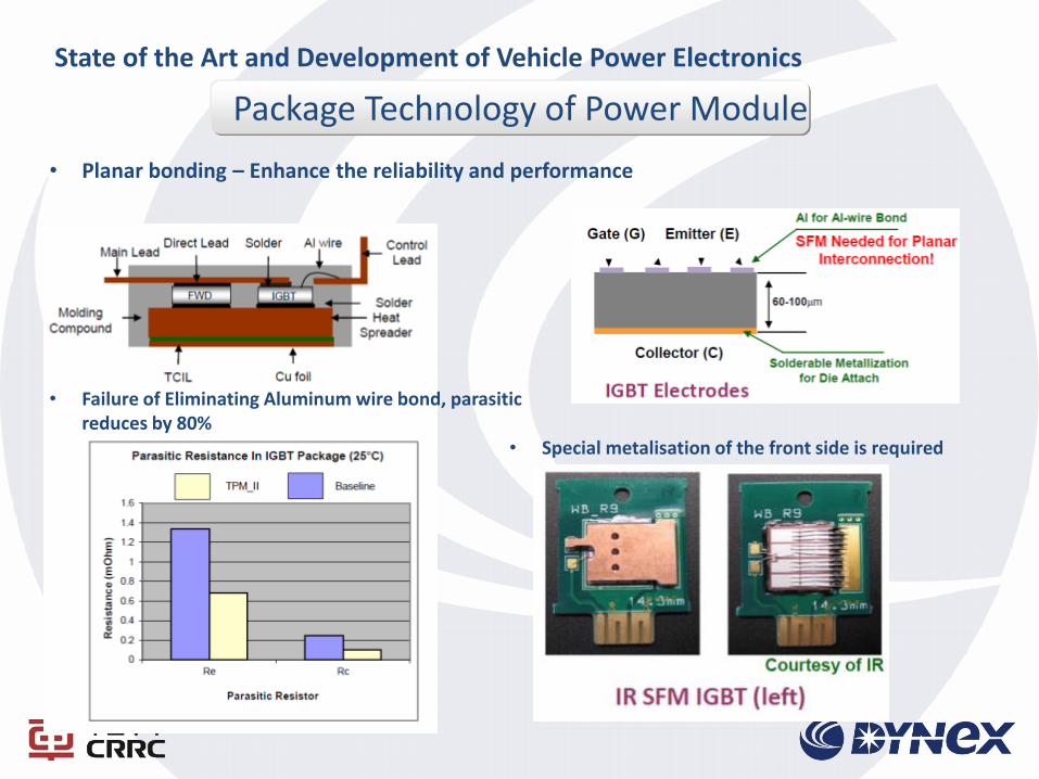
• Planar bonding – Enhance the reliability and performance
• Failure of Eliminating Aluminum wire bond, parasitic reduces by 80%
• Special metalisation of the front side is required
Package Technology of Power Module
State of the Art and Development of Vehicle Power Electronics
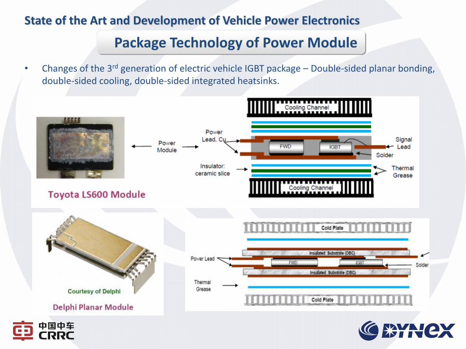
• Changes of the 3rd generation of electric vehicle IGBT package – Double-sided planar bonding, double-sided cooling, double-sided integrated heatsinks.
Package Technology of Power Module
State of the Art and Development of Vehicle Power Electronics
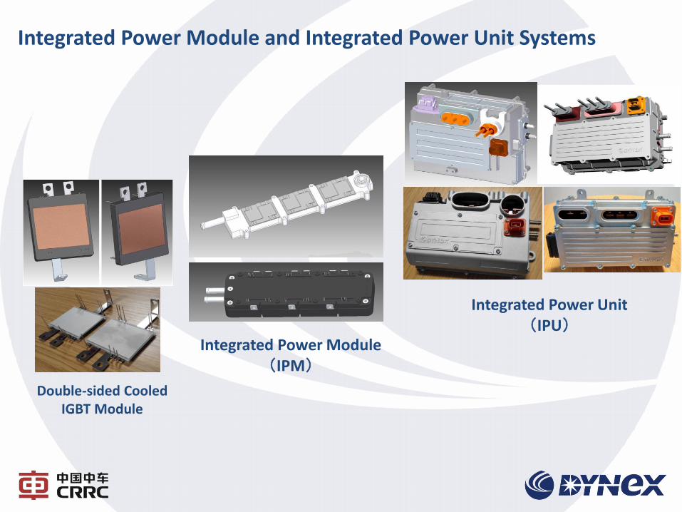
Double-sided Cooled IGBT Module
Integrated Power Module(IPM)
Integrated Power Unit (IPU)
Integrated Power Module and Integrated Power Unit Systems
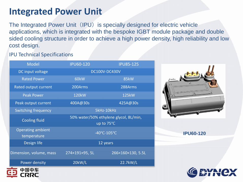
Integrated Power Unit
Model IPU60-120 IPU85-125
DC input voltage DC100V-DC430V
Rated Power 60kW 85kW
Rated output current 200Arms 288Arms
Peak Power 120kW 125kW
Peak output current 400A@30s 425A@30s
Switching frequency 5kHz-10kHz
Cooling fluid 50% water/50% ethylene glycol, 8L/min,
up to 75℃
Operating ambient
temperature -40℃-105℃
Design life 12 years
Dimension, volume, mass 274×191×95, 5L 266×160×130, 5.5L
Power density 20kW/L 22.7kW/L
IPU60-120
IPU Technical Specifications
The Integrated Power Unit(IPU)is specially designed for electric vehicle
applications, which is integrated with the bespoke IGBT module package and double
sided cooling structure in order to achieve a high power density, high reliability and low
cost design.
15
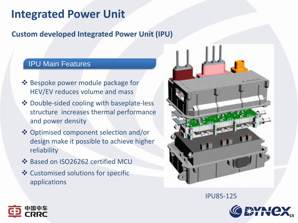
Custom developed Integrated Power Unit (IPU)
IPU Main Features
Bespoke power module package for HEV/EV reduces volume and mass
Double-sided cooling with baseplate-less structure increases thermal performance and power density
Optimised component selection and/or design make it possible to achieve higher reliability
Based on ISO26262 certified MCU
Customised solutions for specific applications
IPU85-125
Integrated Power Unit
16
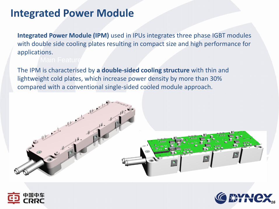
IPU Main Features
Integrated Power Module (IPM) used in IPUs integrates three phase IGBT modules with double side cooling plates resulting in compact size and high performance for applications.
The IPM is characterised by a double-sided cooling structure with thin and lightweight cold plates, which increase power density by more than 30% compared with a conventional single-sided cooled module approach.
Integrated Power Module
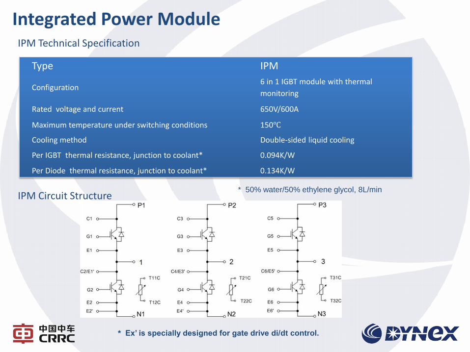
IPM Technical Specification
Type IPM
Configuration 6 in 1 IGBT module with thermal
monitoring
Rated voltage and current 650V/600A
Maximum temperature under switching conditions 150℃
Cooling method Double-sided liquid cooling
Per IGBT thermal resistance, junction to coolant* 0.094K/W
Per Diode thermal resistance, junction to coolant* 0.134K/W
* 50% water/50% ethylene glycol, 8L/min IPM Circuit Structure
* Ex’ is specially designed for gate drive di/dt control.
Integrated Power Module
CONTENT
第一部分 南车株洲所简介
第二部分 电机驱动系统
第三部分 IGBT与组件
COMPANY PROFILE
PART 2 HEV/EV Application
PART 3 Capabilities
PART 1
PART 4 Performance
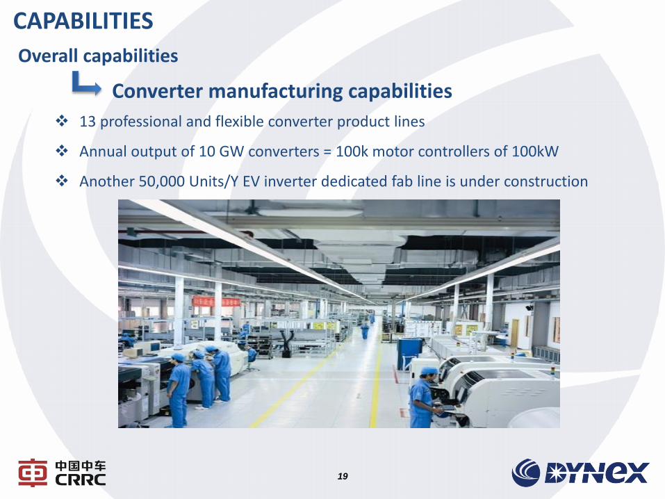
13 professional and flexible converter product lines
Annual output of 10 GW converters = 100k motor controllers of 100kW
Another 50,000 Units/Y EV inverter dedicated fab line is under construction
CAPABILITIES
19
Overall capabilities
Converter manufacturing capabilities
20
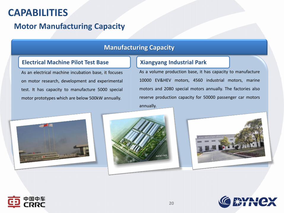
CAPABILITIES Motor Manufacturing Capacity
Manufacturing Capacity
Electrical Machine Pilot Test Base
As an electrical machine incubation base, it focuses
on motor research, development and experimental
test. It has capacity to manufacture 5000 special
motor prototypes which are below 500kW annually.
Xiangyang Industrial Park
As a volume production base, it has capacity to manufacture
10000 EV&HEV motors, 4560 industrial motors, marine
motors and 2080 special motors annually. The factories also
reserve production capacity for 50000 passenger car motors
annually.
21
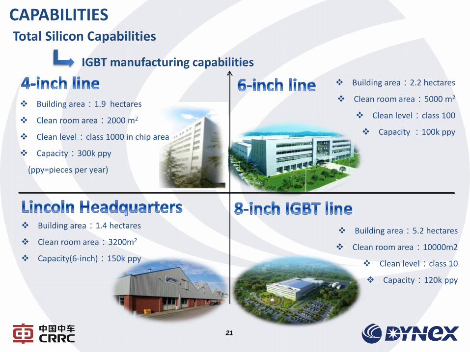
Building area:2.2 hectares
Clean room area:5000 m2
Clean level:class 100
Capacity :100k ppy
Building area:1.9 hectares
Clean room area:2000 m2
Clean level:class 1000 in chip area
Capacity:300k ppy
(ppy=pieces per year)
Building area:1.4 hectares
Clean room area:3200m2
Capacity(6-inch):150k ppy
Building area:5.2 hectares
Clean room area:10000m2
Clean level:class 10
Capacity:120k ppy
CAPABILITIES Total Silicon Capabilities
IGBT manufacturing capabilities
22
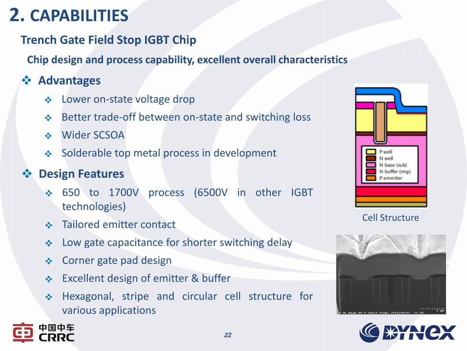
Trench Gate Field Stop IGBT Chip
Chip design and process capability, excellent overall characteristics
Design Features
650 to 1700V process (6500V in other IGBT technologies)
Tailored emitter contact
Low gate capacitance for shorter switching delay
Corner gate pad design
Excellent design of emitter & buffer
Hexagonal, stripe and circular cell structure for various applications
Advantages
Lower on-state voltage drop
Better trade-off between on-state and switching loss
Wider SCSOA
Solderable top metal process in development
Cell Structure
2. CAPABILITIES
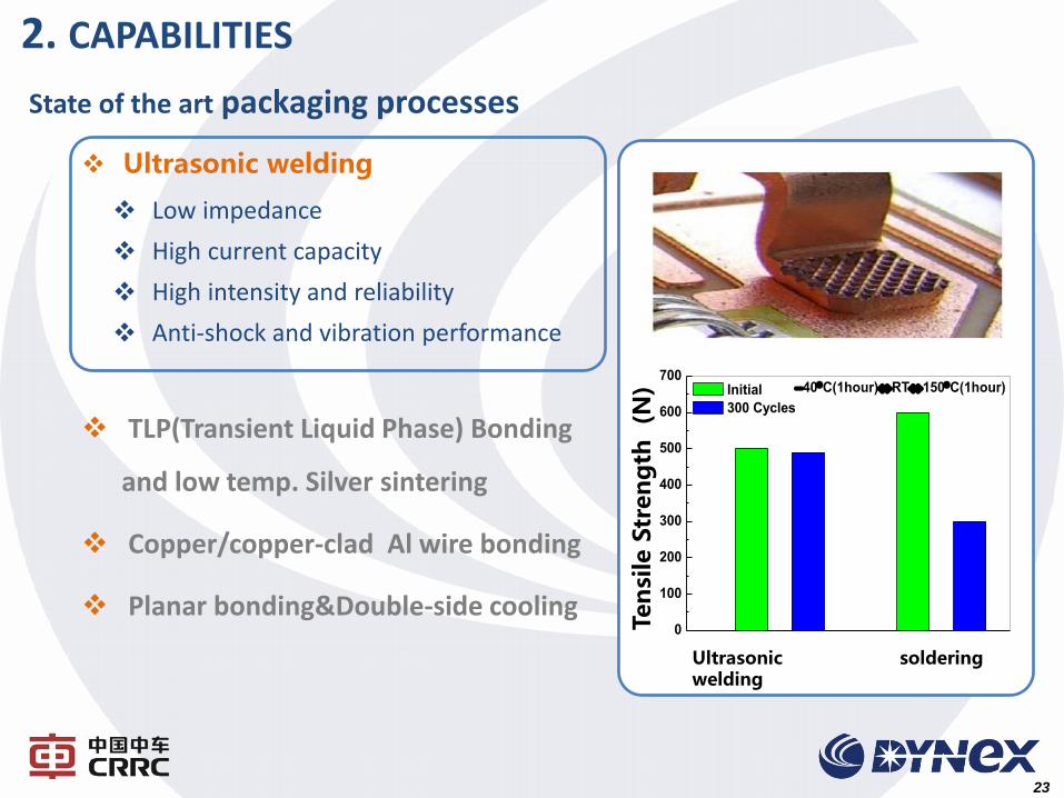
Ultrasonic welding
Low impedance
High current capacity
High intensity and reliability
Anti-shock and vibration performance
TLP(Transient Liquid Phase) Bonding
and low temp. Silver sintering
Copper/copper-clad Al wire bonding
Planar bonding&Double-side cooling
23
State of the art packaging processes
2. CAPABILITIES
Ultrasonic welding
Ten
sile
Str
en
gth
(N
) 0
100
200
300
400
500
600
70040C(1hour)RT150C(1hour)
Initial
300 Cycles
soldering

Ultrasonic welding
TLP (Transient Liquid Phase) Bonding
and low temp. Silver sintering
Low electrical resistivity
High thermal conductivity
High thermal stability
High power cycling capability
Copper/copper-clad Al wire bonding
Planar bonding&Double-side cooling
Pass
Fail
Sintering section SEM
24
State of the art packaging processes
CAPABILITIES
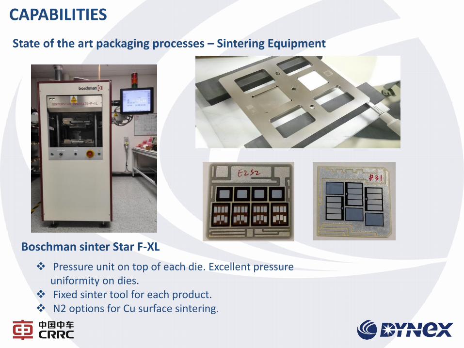
Boschman sinter Star F-XL
Pressure unit on top of each die. Excellent pressure uniformity on dies.
Fixed sinter tool for each product. N2 options for Cu surface sintering.
State of the art packaging processes – Sintering Equipment
CAPABILITIES
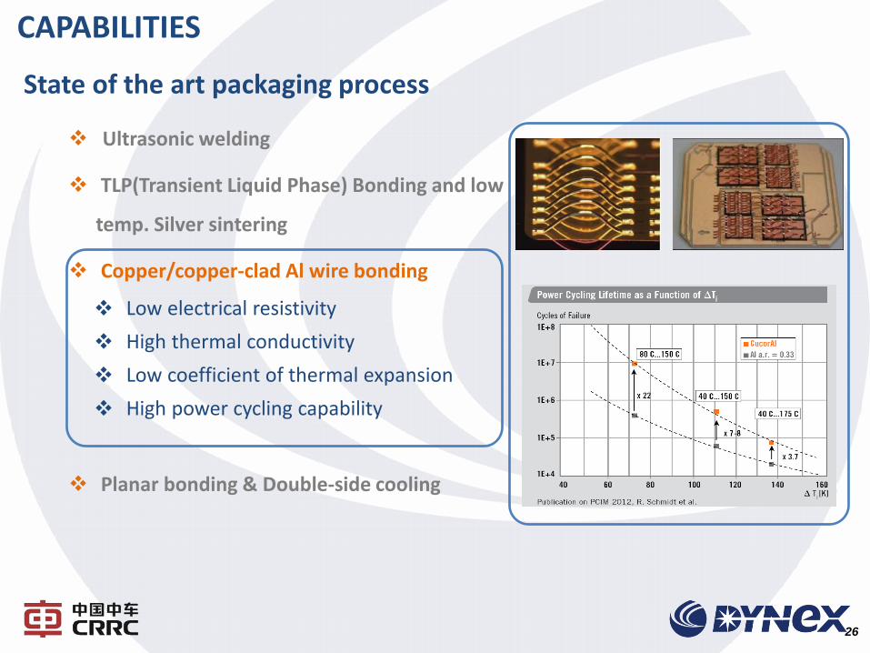
Ultrasonic welding
TLP(Transient Liquid Phase) Bonding and low
temp. Silver sintering
Copper/copper-clad Al wire bonding
Low electrical resistivity
High thermal conductivity
Low coefficient of thermal expansion
High power cycling capability
Planar bonding & Double-side cooling
26
State of the art packaging process
CAPABILITIES
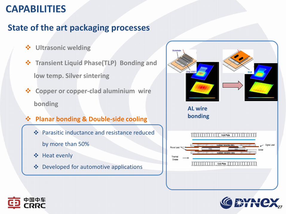
Ultrasonic welding
Transient Liquid Phase(TLP) Bonding and
low temp. Silver sintering
Copper or copper-clad aluminium wire
bonding
Planar bonding & Double-side cooling
Parasitic inductance and resistance reduced
by more than 50%
Heat evenly
Developed for automotive applications
AL wire bonding
27
State of the art packaging processes
CAPABILITIES
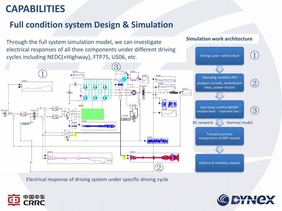
Through the full system simulation model, we can investigate electrical responses of all thee components under different driving cycles including NEDC(+Highway), FTP75, US06, etc.
①
②
③
Driving cycle—vehicle level
Operating condition-IPU
(output current, modulation ratio, power factor)
Operating condition@IGBT module level (transient loss)
Transient junction temperature of IGBT module
Lifetime & reliability analysis
Simulation work architecture
①
②
③ RC network thermal model
Electrical response of driving system under specific driving cycle
Full condition system Design & Simulation
CAPABILITIES
29
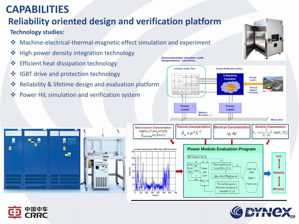
Technology studies:
Machine-electrical-thermal-magnetic effect simulation and experiment
High power density integration technology
Efficient heat dissipation technology
IGBT drive and protection technology
Reliability & lifetime design and evaluation platform
Power HiL simulation and verification system
Reliability oriented design and verification platform CAPABILITIES
Power Module Evaluation Program
30
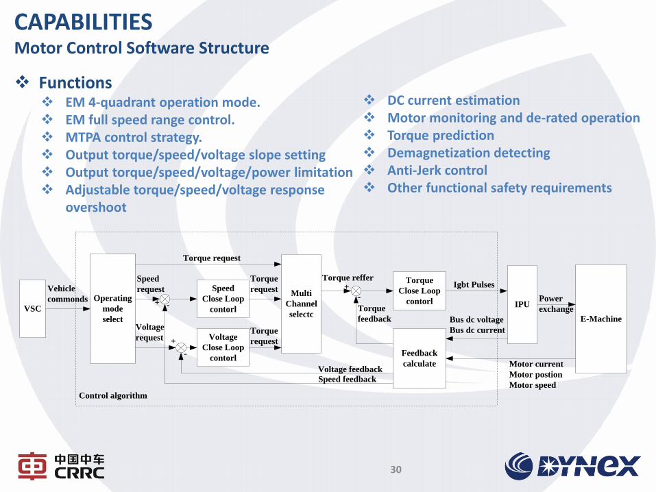
CAPABILITIES Motor Control Software Structure
IPUVSC
E-Machine
Control algorithm
Operating
mode
select
Torque reffer
Torque
feedback
+
-
Torque
Close Loop
contorl
Igbt Pulses
Feedback
calculate
Power
exchange
Motor current
Motor postion
Motor speed
Bus dc voltage
Bus dc current
Speed
Close Loop
contorl
Voltage
Close Loop
contorl
Torque request
Multi
Channel
selectc
Torque
request
+ -
Torque
request
Voltage
request
Vehicle
commonds
Speed
request
-
+
Speed feedback
Voltage feedback
Functions EM 4-quadrant operation mode. EM full speed range control. MTPA control strategy. Output torque/speed/voltage slope setting Output torque/speed/voltage/power limitation Adjustable torque/speed/voltage response
overshoot
DC current estimation Motor monitoring and de-rated operation Torque prediction Demagnetization detecting Anti-Jerk control Other functional safety requirements
31
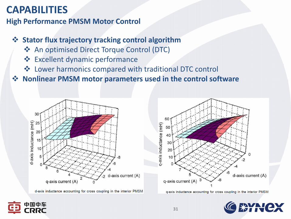
CAPABILITIES High Performance PMSM Motor Control
Stator flux trajectory tracking control algorithm An optimised Direct Torque Control (DTC) Excellent dynamic performance Lower harmonics compared with traditional DTC control
Nonlinear PMSM motor parameters used in the control software
32
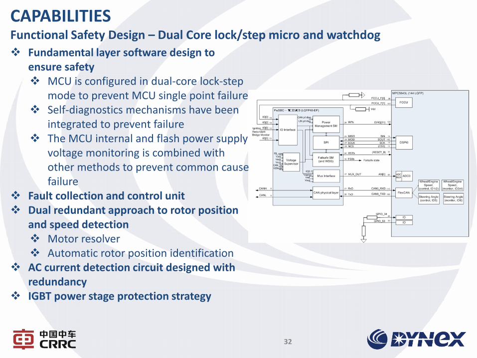
CAPABILITIES Functional Safety Design – Dual Core lock/step micro and watchdog
Fundamental layer software design to ensure safety MCU is configured in dual-core lock-step
mode to prevent MCU single point failure Self-diagnostics mechanisms have been
integrated to prevent failure The MCU internal and flash power supply
voltage monitoring is combined with other methods to prevent common cause failure
Fault collection and control unit Dual redundant approach to rotor position
and speed detection Motor resolver Automatic rotor position identification
AC current detection circuit designed with redundancy
IGBT power stage protection strategy
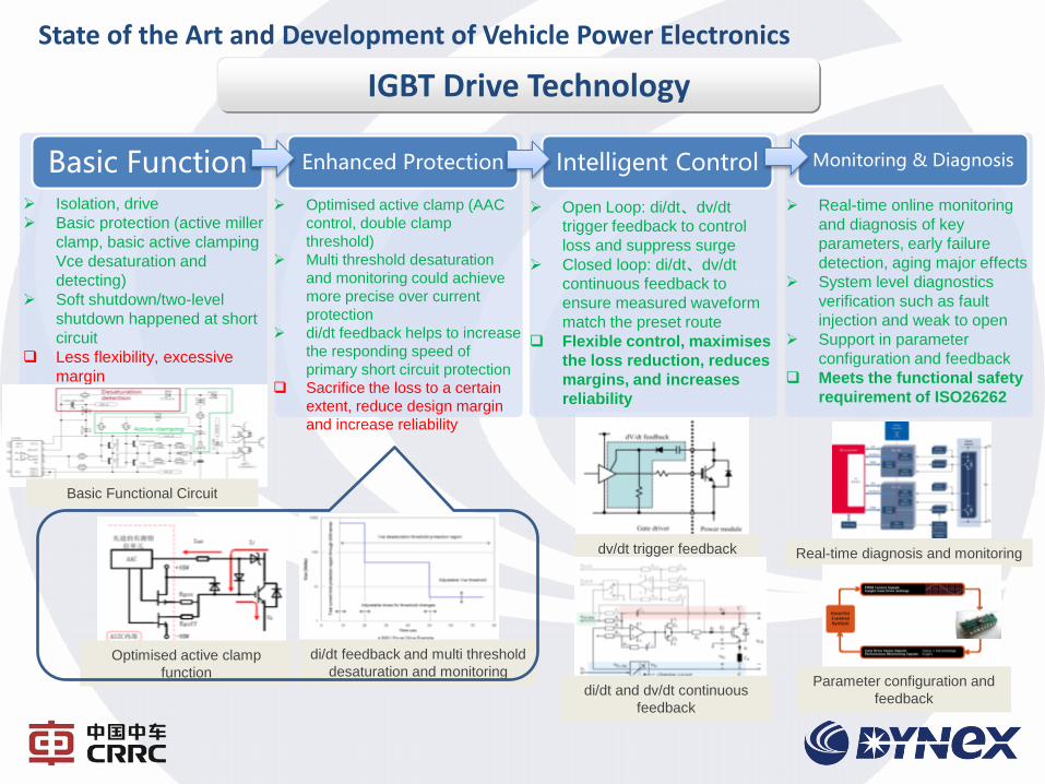
State of the Art and Development of Vehicle Power Electronics
IGBT Drive Technology
Optimised active clamp
function
di/dt feedback and multi threshold
desaturation and monitoring
dv/dt trigger feedback
di/dt and dv/dt continuous
feedback
Real-time diagnosis and monitoring
Parameter configuration and
feedback
Monitoring & Diagnosis Intelligent Control Enhanced Protection Basic Function Isolation, drive
Basic protection (active miller
clamp, basic active clamping
Vce desaturation and
detecting)
Soft shutdown/two-level
shutdown happened at short
circuit
Less flexibility, excessive
margin
Optimised active clamp (AAC
control, double clamp
threshold)
Multi threshold desaturation
and monitoring could achieve
more precise over current
protection
di/dt feedback helps to increase
the responding speed of
primary short circuit protection
Sacrifice the loss to a certain
extent, reduce design margin
and increase reliability
Open Loop: di/dt、dv/dt
trigger feedback to control
loss and suppress surge
Closed loop: di/dt、dv/dt
continuous feedback to
ensure measured waveform
match the preset route
Flexible control, maximises
the loss reduction, reduces
margins, and increases
reliability
Real-time online monitoring
and diagnosis of key
parameters, early failure
detection, aging major effects
System level diagnostics
verification such as fault
injection and weak to open
Support in parameter
configuration and feedback
Meets the functional safety
requirement of ISO26262
Basic Functional Circuit
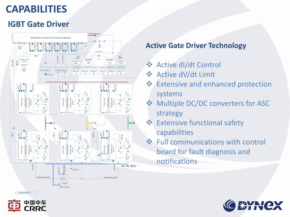
IGBT Gate Driver
Active Gate Driver Technology Active dI/dt Control Active dV/dt Limit Extensive and enhanced protection
systems Multiple DC/DC converters for ASC
strategy Extensive functional safety
capabilities Full communications with control
board for fault diagnosis and notifications
CAPABILITIES
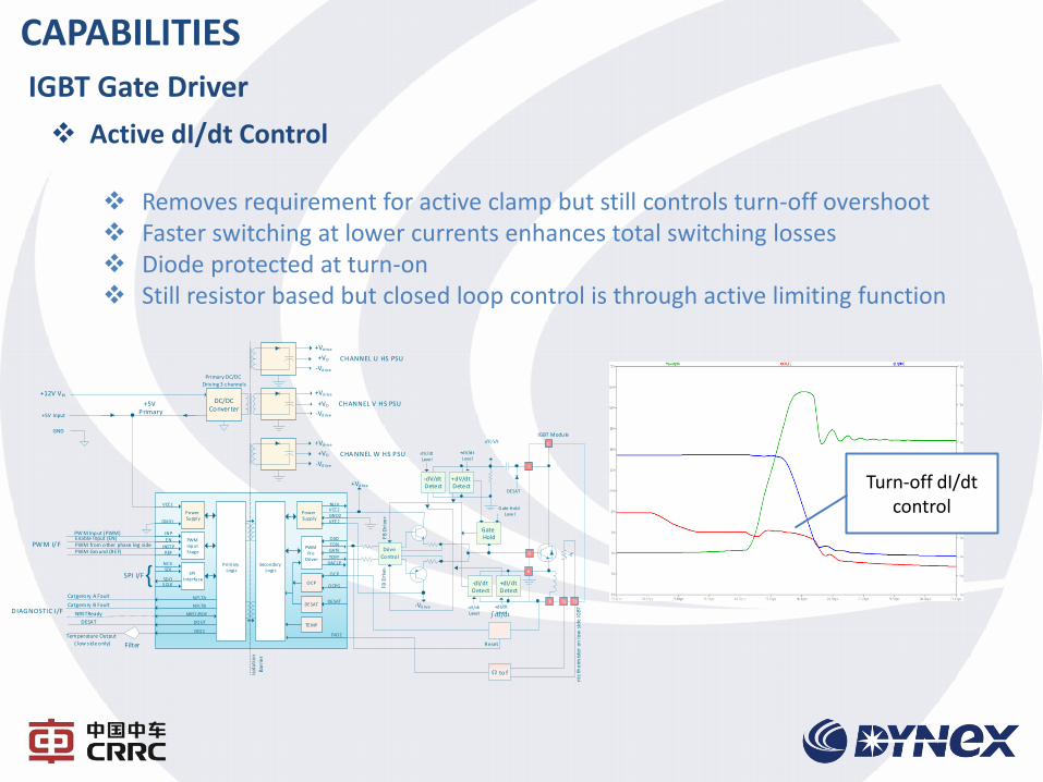
Active dI/dt Control Removes requirement for active clamp but still controls turn-off overshoot Faster switching at lower currents enhances total switching losses Diode protected at turn-on Still resistor based but closed loop control is through active limiting function
Turn-off dI/dt control
IGBT Gate Driver
CAPABILITIES
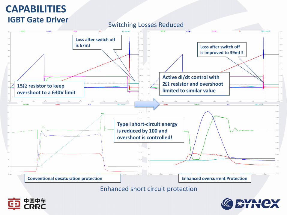
Conventional desaturation protection Enhanced overcurrent Protection
IGBT Gate Driver CAPABILITIES
Switching Losses Reduced
Enhanced short circuit protection
15W resistor to keep overshoot to a 630V limit
Loss after switch off is 67mJ Loss after switch off
is improved to 39mJ!!
Active dI/dt control with 2W resistor and overshoot limited to similar value
Type I short-circuit energy is reduced by 100 and overshoot is controlled!
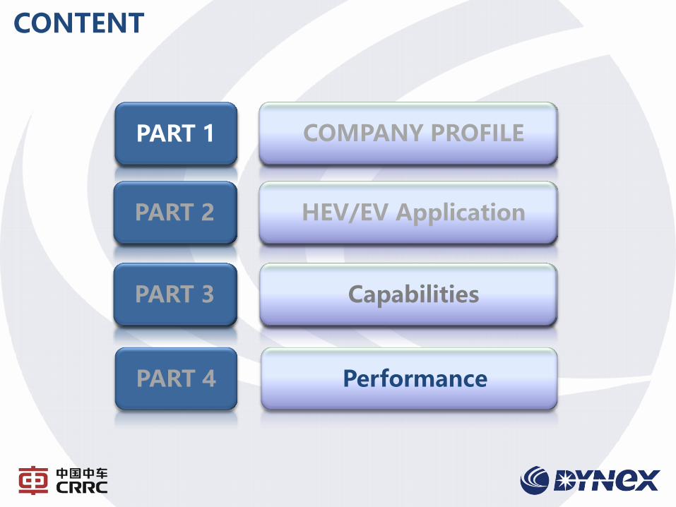
CONTENT
第一部分 南车株洲所简介
第二部分 电机驱动系统
第三部分 IGBT与组件
COMPANY PROFILE
PART 2 HEV/EV Application
PART 3 Capabilities
PART 1
PART 4 Performance
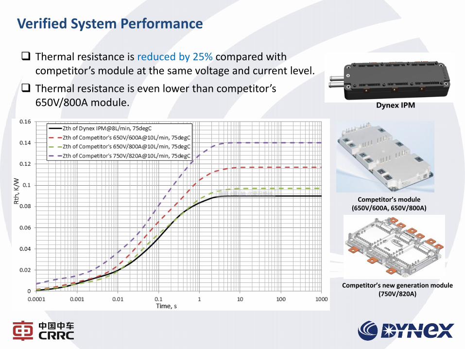
Verified System Performance
Dynex IPM
Competitor’s module (650V/600A, 650V/800A)
Competitor’s new generation module (750V/820A)
Thermal resistance is reduced by 25% compared with competitor’s module at the same voltage and current level.
Thermal resistance is even lower than competitor’s 650V/800A module.
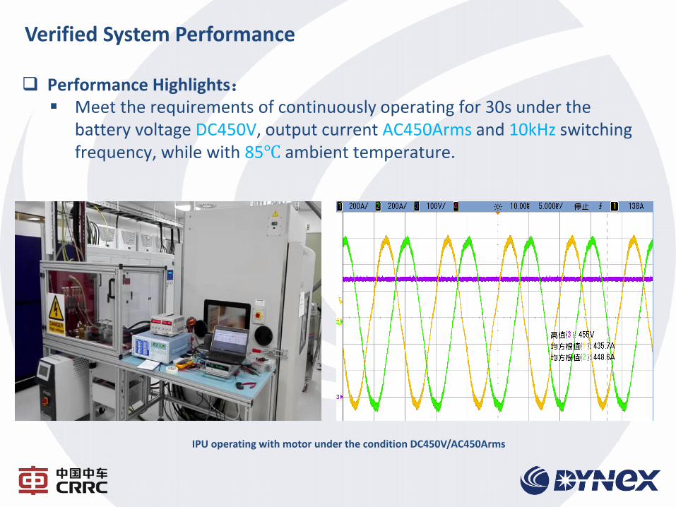
Verified System Performance
Performance Highlights: Meet the requirements of continuously operating for 30s under the
battery voltage DC450V, output current AC450Arms and 10kHz switching frequency, while with 85℃ ambient temperature.
IPU operating with motor under the condition DC450V/AC450Arms
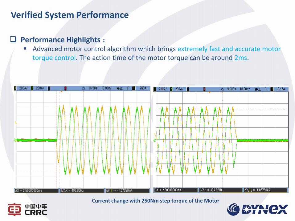
Verified System Performance
Current change with 250Nm step torque of the Motor
Performance Highlights : Advanced motor control algorithm which brings extremely fast and accurate motor
torque control. The action time of the motor torque can be around 2ms.
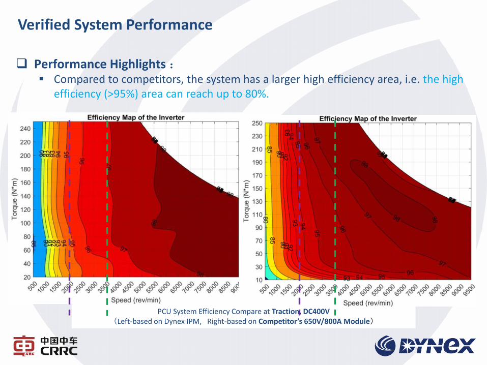
PCU System Efficiency Compare at Traction, DC400V (Left-based on Dynex IPM, Right-based on Competitor’s 650V/800A Module)
Performance Highlights : Compared to competitors, the system has a larger high efficiency area, i.e. the high
efficiency (>95%) area can reach up to 80%.
41/101
Verified System Performance
o Double-sided cooling of IGBT module is becoming the leading technology
of PCU for EVs.
o CRRC-Dynex has developed the known-how and expertise in double-
sided cooling IGBT and PCUs based on this technology.
o According to the benchmarking, the designed double-sided cooling IGBT
and PCU have achieved the highest performance implemented in the
Power Electronics area for EVs.
o The products will be released at the beginning of 2017.
Conclusions
Thank you for listening!
Recommended