Skoog – Chapter 7Components of Optical Instruments
• General Design of Optical Instruments• Sources of Radiation• Wavelength Selectors• Sample Containers• Radiation Transducers (Detectors)• Signal Processors and Readouts• Fiber Optics
Ultraviolet – Visible – Infrared Instrumentation
• Focus our attention on measurements in the UV-vis region of the EM spectrum
• Good instrumentation available• Very widely used techniques• Longstanding and proven methods• IR instrumentation will be considered from
time to time particularly when there are similarities to UV-vis

Absorption measurements require:1) source of radiation2) device for dispersing radiation into component wavelengths3) a means of putting sample into the optical path, i.e., cell4) Detector to convert the EM to an electrical signal5) readout device or circuitry, i.e., meter, computer, recorder, integrator, etc.

Block diagram of instrument for absorption
Light SourceWavelengthSelector
SampleHolder Detector
SignalProcessing
ReadoutDevice
The location of thesecan be reversed
Range of λ’s
Narrow Band of λ’s � Io
Transmitted Intensity � I
Here the wavelengthof interest isselectedfirst, thenpassedthrough the sample
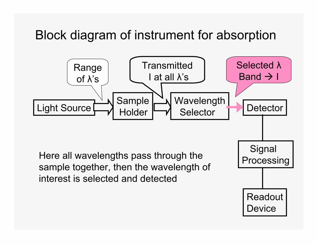
Block diagram of instrument for absorption
Light SourceWavelengthSelector
SampleHolder Detector
SignalProcessing
ReadoutDevice
Range of λ’s
TransmittedI at all λ’s
Selected λBand � I
Here all wavelengths pass through thesample together, then the wavelength ofinterest is selected and detected

Emission measurements require:1) means of exciting emission i.e., way of populating upper energy level which spontaneously emits2) device for dispersing radiation into component wavelengths3) a means of putting sample into the optical path, i.e., cell4) Detector to convert the EM to an electrical signal5) readout device or circuitry, i.e., meter, computer, recorder, integrator, etc.
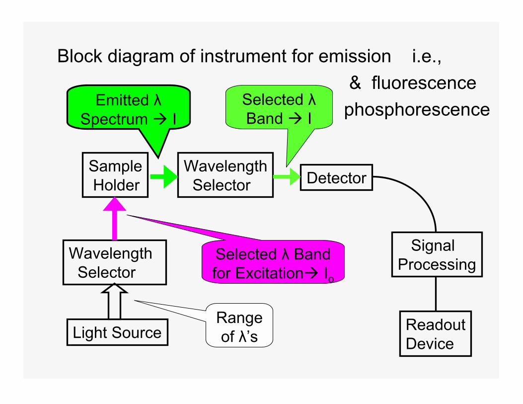
Block diagram of instrument for emission i.e.,& fluorescence
phosphorescence
Light Source
WavelengthSelector
SampleHolder Detector
SignalProcessing
ReadoutDevice
Range of λ’s
Emitted λSpectrum � I
Selected λBand � I
WavelengthSelector
Selected λ Band for Excitation� Io

The requirements for the various components used in different instruments change with the type of spectroscopy as well as for different kinds of measurements within a type of spectroscopy
We will consider the components separately then combine them to make the overall instrument
And finally look at the measurements with regard to theory and practice
Sources – important characteristics1) Spectral distribution i.e., intensity vs. λ
(continuum vs. line sources)2) Intensity3) Stability – short term fluctuations
(noise), long term drift4) Cost5) Lifetime6) Geometry – match to dispersion device

I) CONTINUUM SOURCES1) Thermal radiation (incandescence) –
heated solid emits radiation close to the theoretical “Black Body” radiation i.e., perfect emitter, perfect absorber
Behavior of Black Body- Total power ~ T4 therefore need constant
temperature for stability when using incandescent sources
- Spectral distribution follows Planck’s radiation law

Spectral Distribution Curves of a Tungsten (Black Body) Lamp
At higher temp -> maximumshifts to shorter wavelengths.Low temp good for IR, butvisible region requires high temp.
UV vis IR
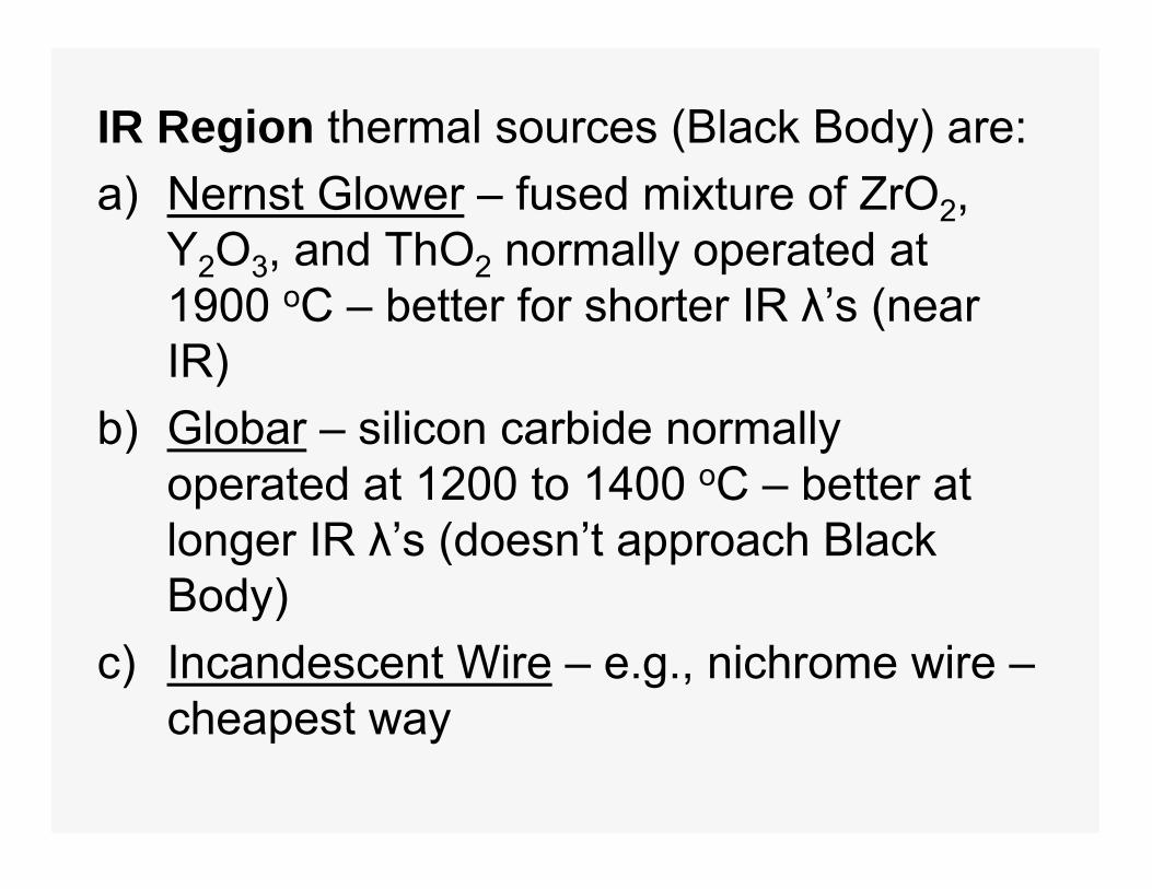
IR Region thermal sources (Black Body) are:a) Nernst Glower – fused mixture of ZrO2,
Y2O3, and ThO2 normally operated at 1900 oC – better for shorter IR λ’s (near IR)
b) Globar – silicon carbide normally operated at 1200 to 1400 oC – better at longer IR λ’s (doesn’t approach Black Body)
c) Incandescent Wire – e.g., nichrome wire –cheapest way

• All operated at relatively low temperature.
• Good for IR and give some visible emission.
• Operated in air so will burn up if temp goes too high
Advantages• Nernst Glower – low power consumption,
operates in air, long lifetime• Globar – more stable than Nernst
Glower, requires more power & must be cooled. Long lifetime, but resistance changes with use

Visible Region sources are:a) Glass enclosed Tungsten (W) filament - normally
operated at ~3000 oK with inert atmosphere to prevent oxidation. Useful from 350 nm to 2000 nm, below 350 nm glass envelope absorbs & emission weak
b) Tungsten-Halogen lamps - can be operated as high as 3500 oK. More intense (high flux). Function of halogen is to form volatile tungsten-halide which redeposits W on filament, i.e., keeps filament from burning out. Requires quartz envelope to withstand high temps (which also transmits down to shorter wavelengths). Fingerprints are a problem – also car headlights

2) Gas Discharge Lamps – two electrodes with a current between them in a gas filled tube. Excitation results from electrons moving through gas. Electrons collide with gas � excitation � emission
At high pressure � “smearing” of energy levels � spectrum approaches continuum
The higher the pressure, the greater the probability that any given molecule or atom will be perturbed by its neighbor at the moment of emission.

a) Hydrogen Lamp- most common source for UV absorption measurements
H2 emission is from180 nm to 370 nmlimited by jacket
Line spectrum from �100 watt HydrogenLamp at low pressure inPyrex

b) Deuterium Lamp – same λdistribution as H2 but with higher intensity (3 to 5 times) -
D2 is a heaviermolecule & movesslower so there isless loss of energyby collisions
High pressure D2 �
with quartz jacket

For higher intensityc) Xenon Lamp – Xe
at high pressure (10-20 atm)
- high pressure neededto get lots of collisionsfor broadeningleading to continuum- short life relatively- arc wander (stabilize)- need jolt to start- output = f(time)
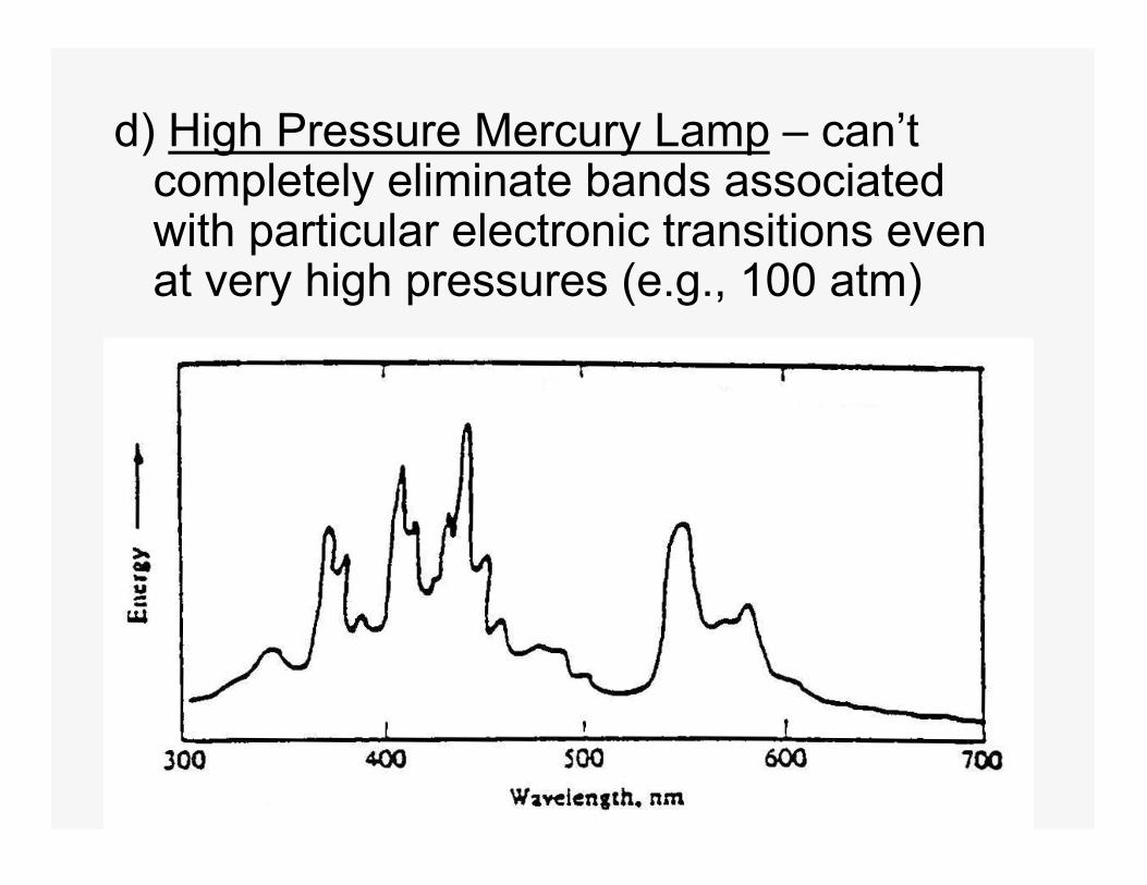
d) High Pressure Mercury Lamp – can’t completely eliminate bands associated with particular electronic transitions even at very high pressures (e.g., 100 atm)

• For UV-vis absorption spectrophotometryusually use H2 for UV and tungsten for visible region (switching mid scan)
• Sometimes use D2 instead of H2
• For fluorescence spectrophotometry use xenon arc lamp in scanning instruments
• Can use He below 200 nm• Hg at low pressure is used in fixed
wavelength (non scanning) fluorometers• Can use mixture of Hg and Xe

II) LINE SOURCES1) Gas (Vapor) Discharge Lamps at low
pressure (i.e., few torr) – minimize collisionalinteraction so get line spectrum- most common are Hg and Na- often used for λ calibration- Hg pen lamp- fluorescent lights are another example- also used UV detectors for HPLC
2) Hollow Cathode Lamps (HCL) – for AA3) Electrodeless Discharge Lamps (EDL) - AA

4) Lasers (Light Amplification by Stimulated Emission of Radiation) –start with material that will exhibit stimulated emission and populate upper states typically using another light source
Stimulated Emission – photon strikes excited state causing it to emit a burst of photons
Pumping source used to populate upper states can be flashlamp, another laser or electrical
Often use prism to select pumping wavelength
Advantages of lasers1) Intense2) Monochromatic – very narrow band3) Coherent – all radiation at same phase
angle

4) Directional – full intensity emitted as beam
Limitations of lasers1) High cost in many cases2) Wavelength range is somewhat limited3) Many operate in pulsed mode – some are
continuous wave (CW)
Pulsed mode lasers are not always problematic as light sources, can use pulse frequency with gated detection

Types of Lasers:1) Solid State Lasers
a) Ruby laser – Al2O3 + Cr(III) -694.3 nm pumped with Xe arc flashlamp –pulsed (can be continuous)
b) Nd/YAG laser – yittrium aluminum garnet + Nd - 1064 nm2) Gas Lasers
a) Neutral atom – He-Ne – 632.8 nm continuous
b) Ion lasers – Ar+ or Kr+ 514.5 nm
c) Molecular lasers – CO2 (10,000 nm = 1000 cm-1) or N2 (337.1 nm) pulsedd) Eximer lasers – inert gas + fluorine creates eximers ArF+ (193 nm), KrF+ (248 nm), XeF+ (351) pulsed
3) Dye Lasers – tunable over 20 – 50 nm many dyes available for wide range of λ’s
4) Semiconductor Diode Lasers – wide range of λ’s available, continuous

Wavelength SelectionThree main approaches:
1) Block off unwanted radiation –optical filters2) Disperse radiation & select desired band – monochromator3) Modulate wavelengths at different frequencies - interferometer
FILTERS1) Absorption – colored glass, colored film, colored solutions – cheapest way

Assortment of Glass & Quartz Optical Filters

Transmittance Curves for Optical Filters
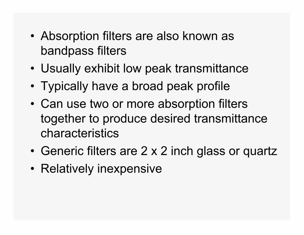
• Absorption filters are also known as bandpass filters
• Usually exhibit low peak transmittance• Typically have a broad peak profile• Can use two or more absorption filters
together to produce desired transmittance characteristics
• Generic filters are 2 x 2 inch glass or quartz• Relatively inexpensive

Cut-off filters or sharp-cut filters are also available such as the 650 nm cut-off filter shown hereCut-on filters have reverse profile

Combining two appropriate cut-off filters producesa bandpass filter. The example shown here comesfrom 3 filters producing bands at 500 & 600 nm.

Two terms associated with optical filters are:
1) Effective bandwidthmeasured at ½ peak height2) Nominal wavelengthThese filters have nominal
wavelengths of 450& 500 nm

2) Interference filters – usually Fabrey-Perot type
Incident light beam
Transmittedradiation
Glasslayers
Dielectric material (CaF or MgF)
Semi-reflectivemetal layers
Light bounces back& forth & gets out ofphase with itselfunless it meetsconditions forconstructive interference
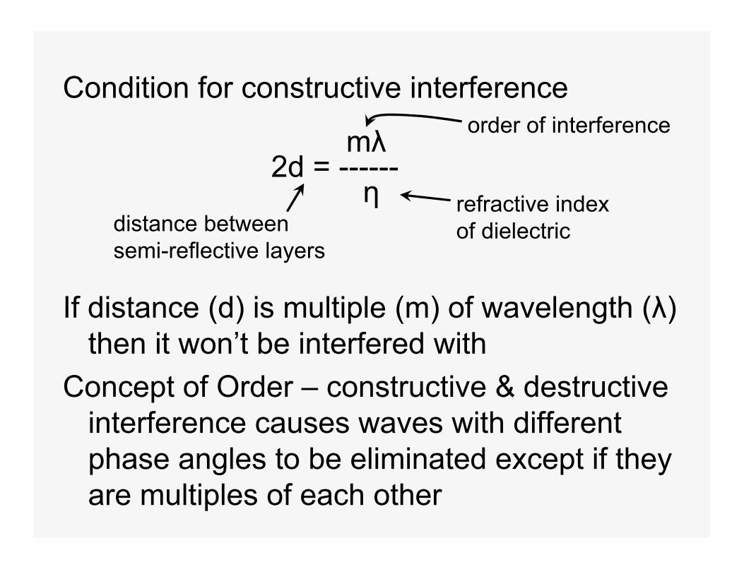
Condition for constructive interference
mλ2d = ------
η
If distance (d) is multiple (m) of wavelength (λ) then it won’t be interfered with
Concept of Order – constructive & destructive interference causes waves with different phase angles to be eliminated except if they are multiples of each other
distance betweensemi-reflective layers
order of interference
refractive indexof dielectric
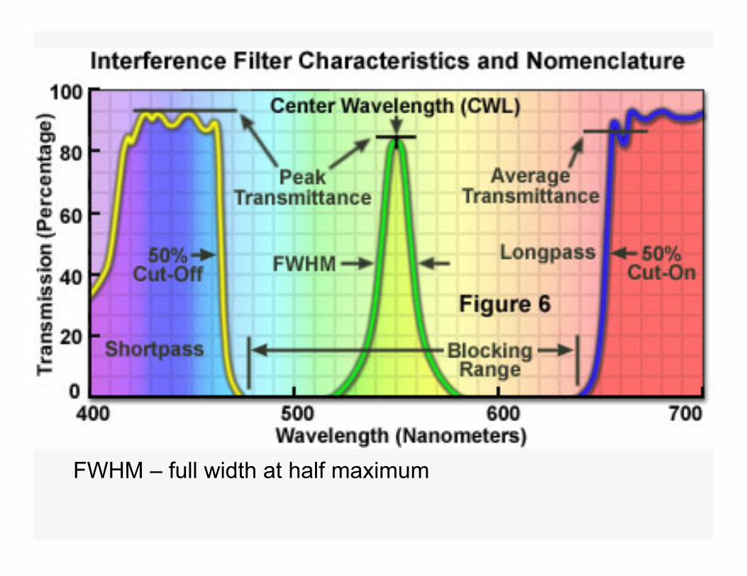
FWHM – full width at half maximum

Transmittance vs. wavelength for typical Fabrey-Perot Interference filter showing first and second order λ’s (m = 1 & m = 2)
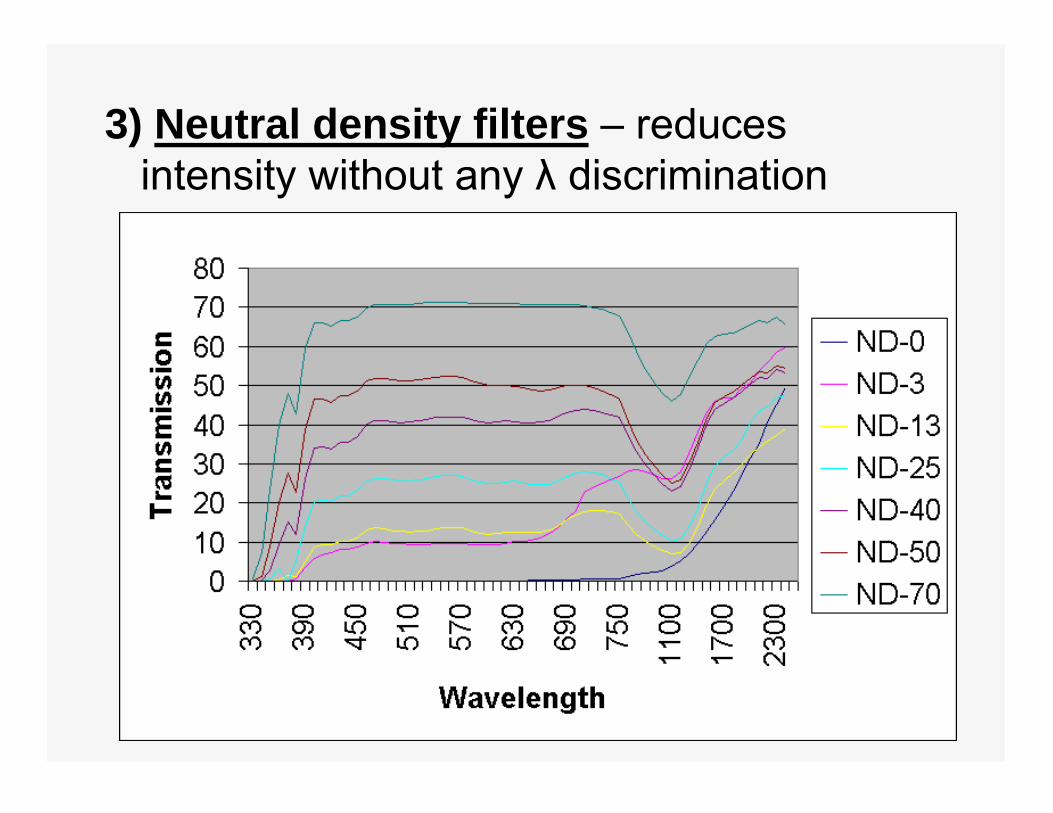
3) Neutral density filters – reduces intensity without any λ discrimination

II) MONOCHROMATORS
sourcedetectorlocation
Simple Prism Monochromator
Entrance slit allows source radiation to illuminate the first lenswhich collimates the light spreading it across the face of theprism. Prism disperses radiation into component wavelengthsand the second lens focuses the spectrum at the focal plane.An exit slit selects the band of radiation to reach the detector.Dispersing element can be a prism or a diffraction grating.Focusing elements can be lenses or mirrors.
Focalplane
• Optical Materials – need optically transparent materials for lenses, prisms & sample cells
• In visible region – can use glass down to 350 nm
• In the UV region – quartz is material of choice
• In the IR region – NaCl, KBr, etc. The heavier the atoms of the salt, the farther into the IR region (i.e., longer λ) before significant absorption occurs
Problem – sensitivity to moisture
Recommended
![17. Optical detectors and displays Optical displaysoptics.hanyang.ac.kr/~shsong/17-Optical detectors and...Microsoft PowerPoint - 17-Optical detectors and displays.ppt [호환 모드]](https://img.pdfslide.tips/doc/110x75/5fe09b29a01b753bbc41e408/17-optical-detectors-and-displays-optical-shsong17-optical-detectors-and-microsoft.jpg)