Truly Useful 3D Drawing System for Professional
Designer by “Life-sized and Operable” Feature and
New Interaction
Shun'ichi Tano 1, Shinya Yamamoto
1, Junko Ichino
1, Tomonori Hashiyama
1 and
Mitsuru Iwata 2
1 University of Electro-Communications, Graduate School of Information Systems,
1-5-1 Chifugaoka, Chofu-shi, Tokyo, Japan 2 Tokyo Metropolitan College of Industrial Technology,
1-10-40 Higashioi, Shinagawa-ku, Tokyo, Japan
Abstract. “Media” is an artifact that expands our creativity and intelligence.
We have been studying the use of “Rich Media” to support creative and intelli-
gent human activities. Specifically, for over ten years we have focused on the
3D space as one of “Rich Media” and developed many 3D sketch systems that
support the design of 3D objects. However, their long-term evaluation has re-
vealed that they are not used by designers in real fields. Even worse, they are
treated as if they were just mere attractions in an amusement park. The funda-
mental problem is the lack of the indispensable function for 3D space. In this
paper, we propose new design principles, “life-size and operability”, which
make the 3D sketch system truly valuable for the designer. The new 3D sketch
system is designed on the basis of “life-size and operability”, developed, and
evaluated successfully.
Keywords: 3D Sketch; Life-size; Operability; Professional Designer; Mixed
reality.
1 Introduction
”Media” is an artifact that expands our creativity and intelligence. The oldest media is
words and numbers. The computer is now widely used as a media.
We have been studying a wide range of creativity-centered media to ensure that
systems truly support creative and intelligent human activities. They range from those
used by knowledge workers to those for car-exterior designers [1-9].
Specifically, for over ten years we have developed many 3D sketch systems that
support the design of 3D objects, because the 3D sketch cannot be realized without
the power of advanced information communication technology (ICT) [6-9]. We re-
garded the 3D sketch as the drastic extension of the traditional “pen and paper” media
made possible by the power of ICT.
However, long-term evaluation has revealed that 3D sketches are not used by de-
signers in real fields. Even worse, they are treated as if they were just mere attractions
in an amusement park.
It shows that the rich media certainly fascinates the ordinary users but is ignored by
the professional users in some cases. It may be the serious problem because there are
many systems that blindly utilize the rich multimedia without the long-term user
evaluation [18].
In this paper, we analyze the fundamental problems that prevent the systems from
being used professionally. We point out that it is the lack of the indispensable func-
tion for 3D space. Then we propose a new design concept inspired by “mixed reality”,
that makes the 3D sketch system truly valuable for the designer, and exemplify the
feasibility of the new design concept by describing our latest prototype system.
2 Related Works and Purpose
2.1 Related works
Conventional research into 3D sketching can be categorized into two types. The first
is generating 3D sketches from 2D sketches [15, 16]. The designer draws a 2D sketch,
then the system converts it into a 3D sketch on the basis of certain assumptions, and
finally the system displays it in a 3D space.
The second is drawing the 3D sketch directly in midair [10-14, 17]. The 3D lines
are displayed as they are or as transformed smooth lines and converted into the model
description in some systems [14, 17].
We have also developed a series of 3D sketch systems [6-9] in both categories
mentioned above.
Although each system has its own strength and has been successfully evaluated by
the designers, the common problem is that they are not utilized continuously by pro-
fessional designers in daily design tasks over long periods of time. They are missing
something that would make them indispensable for professional use.
2.2 Purpose of this paper
In this paper, first the role of 3D space is categorized into two types: “draw in 3D
space” and “view in 3D space”.
Second, our four trial systems are briefly shown as examples that support all roles
of 3D space.
Third, the long-term evaluation of the four trial systems is summarized. It shows
that the fundamental problem is the lack of indispensable functions for 3D space.
Fourth, we propose new design principles “life-size and operability”, which make
the 3D sketch system truly valuable for the professional designer.
Finally, our latest 3D sketch system designed by the new design principle is ex-
plained in detail and evaluated by professional designers.
3 Our Trials for 3D Sketch System
We have developed a series of 3D sketch systems. The following subsection describes
four typical systems [6-9] (called Systems 1, 2, 3 and 4).
3.1 Role of 3D Space
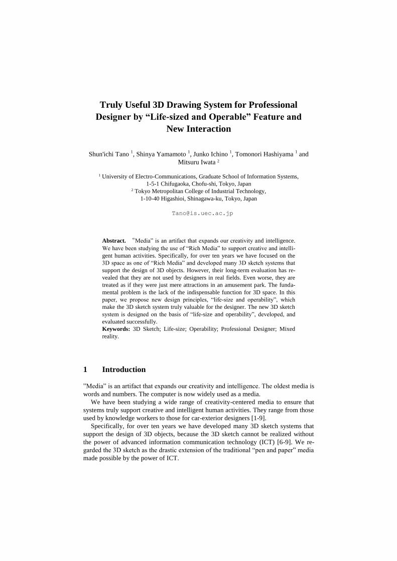
2D/3D space can be used in two ways as shown in Fig. 1. The first is the space where
the designer draws the objects. To draw in 3D space means to draw objects in the 3D
space directly, i.e., for designers to sketch them in midair in front of themselves. To
draw in 2D space means to draw objects in the 2D space, i.e., using a pen and paper.
The second one is the space where the designer looks at the objects. To view in
3D space means designers look at objects in midair in front of them (stereovision). To
view in 2D space means to look at objects as perspective 2D images on the 2D plane.
Fig. 1. “Draw in 2D/3D space” and “view in 2D/3D space”.
Systems 1 and 2 support the 2D-draw and 2D/3D-view. The designer draws a 2D
sketch and views it both in stereovision in the 3D space and as a perspective 2D im-
age on the 2D plane. The reason the systems do not support 3D-draw is the difficulty
of drawing in a 3D space directly.
Systems 3 and 4 have a mechanism to compensate for this difficulty, so they sup-
port the 3D-draw and 3D-view.
3.2 Our 3D system-1: “Godzilla”
System 1, called “Godzilla”, aims to support creative design, specifically that of car-
exterior designers.
3.2.1 Design Flow
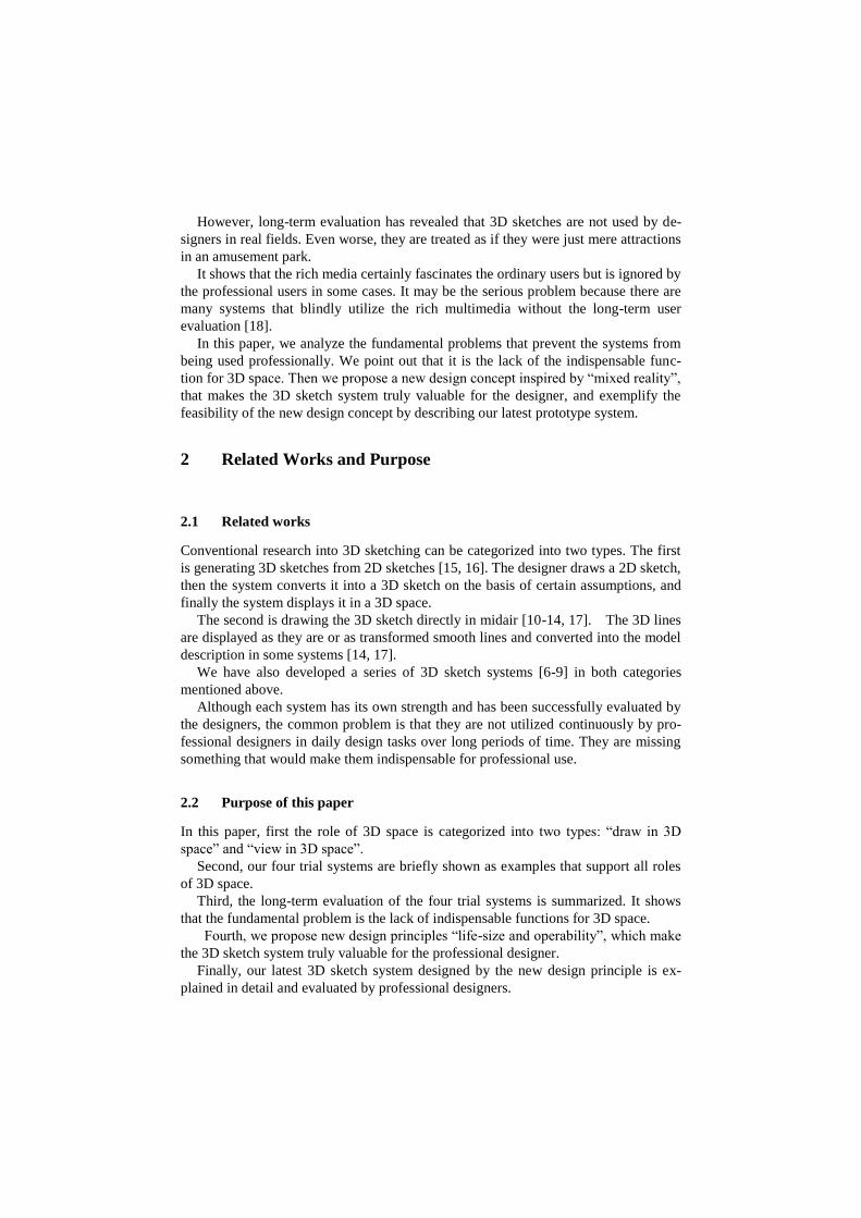
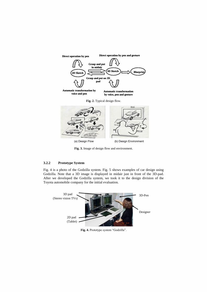
Fig. 2 shows the typical design flow. First, the designer draws the concept image on
the 2D pad (a tablet with an LCD) as shown in Fig. 3(a). The designer can grasp the
sketch and hold it in midair, and it appears as a 3D image on the 3D pad (stereovision
TV) as shown in Fig. 3(b). While holding and rotating the 3D-image, the designer can
look at it from different viewpoints. When the designer grasps the image and puts it
onto the 2D pad, it appears on the 2D pad as a 2D sketch. Note that our system dis-
plays a hand-drawn sketch all the time, even in the 3D space, and can automatically
recognize the 3D shape of a 2D image and transform between the 2D and 3D sketches
with different viewpoints while preserving the designer's pen touch.
Systems 3 and 4
Systems 1 and 2
2D Space 3D Space
Draw
View
2D pad
(Tablet)
3D pad
(Stereo vision TVs) 3D-Pen
Designer
Fig. 2. Typical design flow.
Fig. 3. Image of design flow and environment.
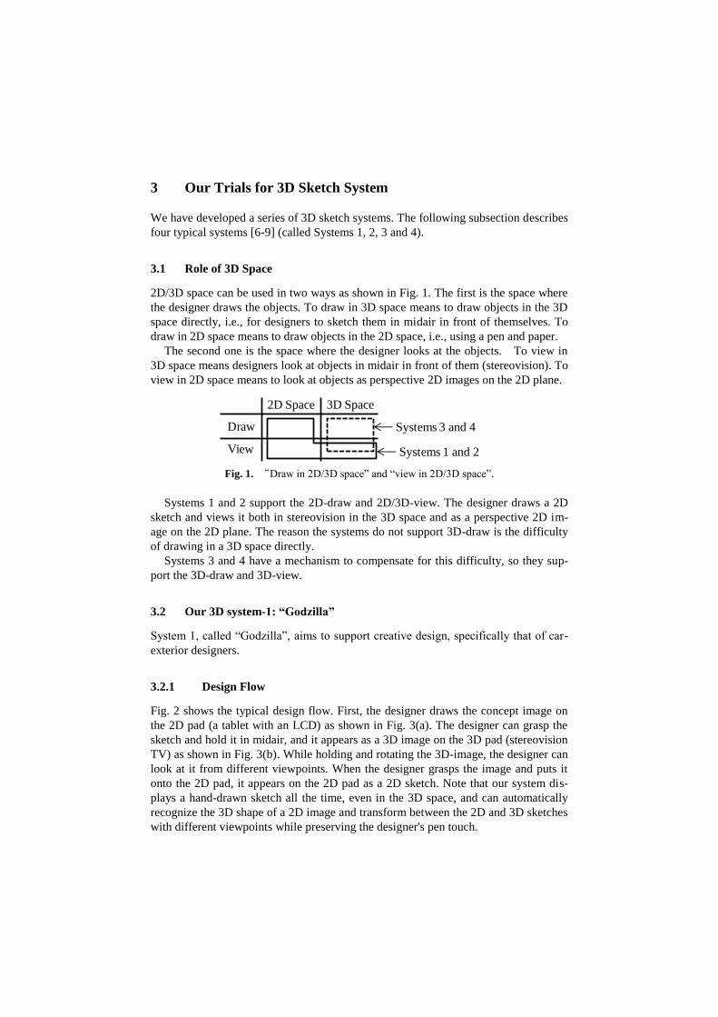
3.2.2 Prototype System
Fig. 4 is a photo of the Godzilla system. Fig. 5 shows examples of car design using
Godzilla. Note that a 3D image is displayed in midair just in front of the 3D-pad.
After we developed the Godzilla system, we took it to the design division of the
Toyota automobile company for the initial evaluation.
Fig. 4. Prototype system “Godzilla”.
Grasp and put
in midair
Grasp and put on 2D
pad
Direct operation by pen and gesture
3D Sketch
Automatic transformation
by voice, pen and gesture
Automatic transformation by
voice and pen
Direct operation by pen
Blueprint2D Sketch
Grasp and put
in midair
Grasp and put on 2D
pad
Direct operation by pen and gesture
3D Sketch
Automatic transformation
by voice, pen and gesture
Automatic transformation by
voice and pen
Direct operation by pen
Blueprint2D Sketch
(a) Design Flow (b) Design Environment
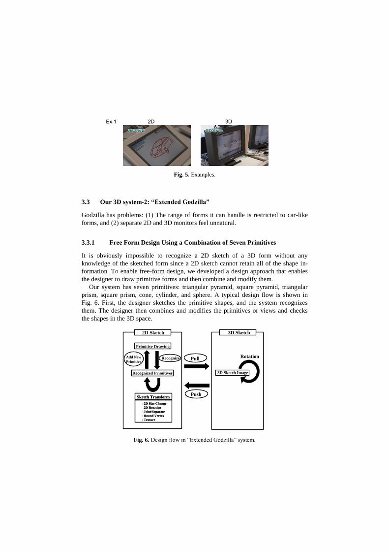
Fig. 5. Examples.
3.3 Our 3D system-2: “Extended Godzilla”
Godzilla has problems: (1) The range of forms it can handle is restricted to car-like
forms, and (2) separate 2D and 3D monitors feel unnatural.
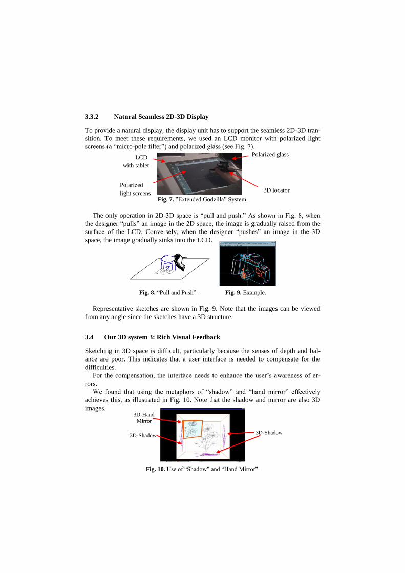
3.3.1 Free Form Design Using a Combination of Seven Primitives
It is obviously impossible to recognize a 2D sketch of a 3D form without any
knowledge of the sketched form since a 2D sketch cannot retain all of the shape in-
formation. To enable free-form design, we developed a design approach that enables
the designer to draw primitive forms and then combine and modify them.
Our system has seven primitives: triangular pyramid, square pyramid, triangular
prism, square prism, cone, cylinder, and sphere. A typical design flow is shown in
Fig. 6. First, the designer sketches the primitive shapes, and the system recognizes
them. The designer then combines and modifies the primitives or views and checks
the shapes in the 3D space.
Fig. 6. Design flow in “Extended Godzilla” system.
Ex.1 2D 3D
3D Sketch2D Sketch
Recognized Primitives
Primitive Drawing
3D Sketch Image
Sketch Transform
- 2D Size Change
- 2D Rotation
- Joint/Separate
- Round Vertex
- Texture
Recognize RotationPullAdd New
Primitive
Push
3D Sketch2D Sketch
Recognized Primitives
Primitive Drawing
3D Sketch Image
Sketch Transform
- 2D Size Change
- 2D Rotation
- Joint/Separate
- Round Vertex
- Texture
Recognize RotationPullAdd New
Primitive
Push
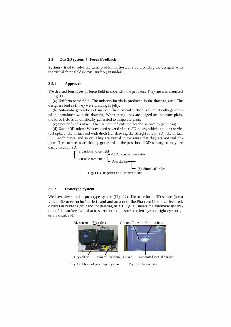
3.3.2 Natural Seamless 2D-3D Display
To provide a natural display, the display unit has to support the seamless 2D-3D tran-
sition. To meet these requirements, we used an LCD monitor with polarized light
screens (a “micro-pole filter”) and polarized glass (see Fig. 7).
Fig. 7. ”Extended Godzilla” System.
The only operation in 2D-3D space is “pull and push.” As shown in Fig. 8, when
the designer “pulls” an image in the 2D space, the image is gradually raised from the
surface of the LCD. Conversely, when the designer “pushes” an image in the 3D
space, the image gradually sinks into the LCD.
Fig. 8. “Pull and Push”. Fig. 9. Example.
Representative sketches are shown in Fig. 9. Note that the images can be viewed
from any angle since the sketches have a 3D structure.
3.4 Our 3D system 3: Rich Visual Feedback
Sketching in 3D space is difficult, particularly because the senses of depth and bal-
ance are poor. This indicates that a user interface is needed to compensate for the
difficulties.
For the compensation, the interface needs to enhance the user’s awareness of er-
rors.
We found that using the metaphors of “shadow” and “hand mirror” effectively
achieves this, as illustrated in Fig. 10. Note that the shadow and mirror are also 3D
images.
Fig. 10. Use of “Shadow” and “Hand Mirror”.
Polarized glass
3D locator Polarized
light screens
LCD
with tablet
3D-Shadow
3D-Hand
Mirror
3D-Shadow
3.5 Our 3D system-4: Force Feedback
System 4 tried to solve the same problem as System 3 by providing the designer with
the virtual force field (virtual surface) in midair.
3.5.1 Approach
We devised four types of force field to cope with the problem. They are characterized
in Fig. 11.
(a) Uniform force field: The uniform inertia is produced in the drawing area. The
designers feel as if they were drawing in jelly.
(b) Automatic generation of surface: The artificial surface is automatically generat-
ed in accordance with the drawing. When many lines are judged on the same plain,
the force field is automatically generated to shape the plain.
(c) User-defined surface: The user can indicate the needed surface by gesturing.
(d) Use of 3D rulers: We designed several virtual 3D rulers, which include the vir-
tual sphere, the virtual rod with ditch (for drawing the straight line in 3D), the virtual
3D French curve, and so on. They are virtual in the sense that they are not real ob-
jects. The surface is artificially generated at the position of 3D sensor, so they are
easily fixed in 3D.
Fig. 11. Categories of four force fields.
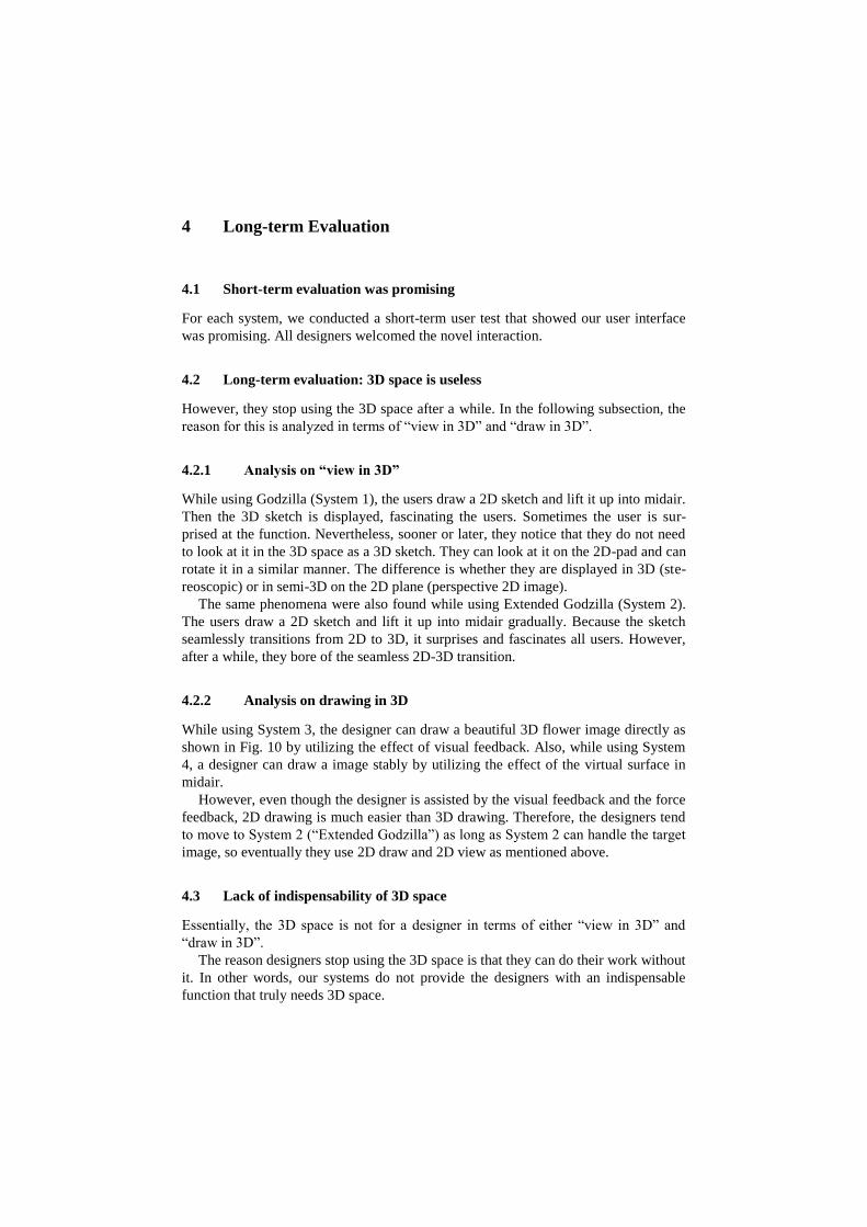
3.5.2 Prototype System
We have developed a prototype system (Fig. 12). The user has a 3D-sensor (for a
virtual 3D-ruler) in his/her left hand and an arm of the Phantom (the force feedback
device) in his/her right hand for drawing in 3D. Fig. 13 shows the automatic genera-
tion of the surface. Note that it is seen in double since the left-eye and right-eye imag-
es are displayed.
Fig. 12. Photo of prototype system. Fig. 13. User interface.
(a)Uniform force field (b) Automatic generation
(d) Virtual 3D ruler
Variable force field User define
3D sensor (3D-ruler) Group of lines Corn-pointer
CrystalEys Arm of Phantom (3D-pen) Generated virtual surface
4 Long-term Evaluation
4.1 Short-term evaluation was promising
For each system, we conducted a short-term user test that showed our user interface
was promising. All designers welcomed the novel interaction.
4.2 Long-term evaluation: 3D space is useless
However, they stop using the 3D space after a while. In the following subsection, the
reason for this is analyzed in terms of “view in 3D” and “draw in 3D”.
4.2.1 Analysis on “view in 3D”
While using Godzilla (System 1), the users draw a 2D sketch and lift it up into midair.
Then the 3D sketch is displayed, fascinating the users. Sometimes the user is sur-
prised at the function. Nevertheless, sooner or later, they notice that they do not need
to look at it in the 3D space as a 3D sketch. They can look at it on the 2D-pad and can
rotate it in a similar manner. The difference is whether they are displayed in 3D (ste-
reoscopic) or in semi-3D on the 2D plane (perspective 2D image).
The same phenomena were also found while using Extended Godzilla (System 2).
The users draw a 2D sketch and lift it up into midair gradually. Because the sketch
seamlessly transitions from 2D to 3D, it surprises and fascinates all users. However,
after a while, they bore of the seamless 2D-3D transition.
4.2.2 Analysis on drawing in 3D
While using System 3, the designer can draw a beautiful 3D flower image directly as
shown in Fig. 10 by utilizing the effect of visual feedback. Also, while using System
4, a designer can draw a image stably by utilizing the effect of the virtual surface in
midair.
However, even though the designer is assisted by the visual feedback and the force
feedback, 2D drawing is much easier than 3D drawing. Therefore, the designers tend
to move to System 2 (“Extended Godzilla”) as long as System 2 can handle the target
image, so eventually they use 2D draw and 2D view as mentioned above.
4.3 Lack of indispensability of 3D space
Essentially, the 3D space is not for a designer in terms of either “view in 3D” and
“draw in 3D”.
The reason designers stop using the 3D space is that they can do their work without
it. In other words, our systems do not provide the designers with an indispensable
function that truly needs 3D space.
5 New Design Concept
As long as an indispensable function of 3D space is not found, it is pointless to devel-
op a support system that uses 3D space. Therefore, we stopped our research into 3D
space for a few years. Recently, we found indispensable functions and restarted the
research activity. Here, the latest findings and the current prototype system are
shown.
5.1 Indispensable functions of 3D space
We found two indispensable functions that need the 3D space. The first one is a life-
sized 3D sketch. If the 3D sketch is life-sized, the user evaluates the size to compare
their own body and the 3D sketch shown in the midair in front of the user.
If the “life-sized” nature is missing, the users cannot evaluate it on the basis of
comparison with their body, so the necessity of 3D sketch is lost.
The second one is a 3D sketch that must be operable by the user. The user should
be able to operate the 3D sketch, that is, touch, push, move, and so on. If the 3D
sketch is operable, the user evaluates the ease of use by operating while stooping
down, extending a hand, or twisting his/her body.
5.2 Design concept “Life-sized and operable”
The 3D sketches must have a “life-sized and operable” nature. Since the life-sized 3D
sketch can be evaluated by comparison with a user’s body, it needs to be displayed in
a 3D space in front of the user. For example, the user can notice that the table of this
kitchen is low or the emergency button is far from the operator’s chair.
Similarly, since users can evaluate the operational 3D sketch by moving their bod-
ies while operating, it needs to be displayed in a 3D space in front of the users. For
example, the user can notice when operating a lever that the warning lamp is hard to
see or the tray of the copy machine is too low to remove the paper jam.
6 New 3D Sketch System with Mixed Reality
6.1 New Design Flow
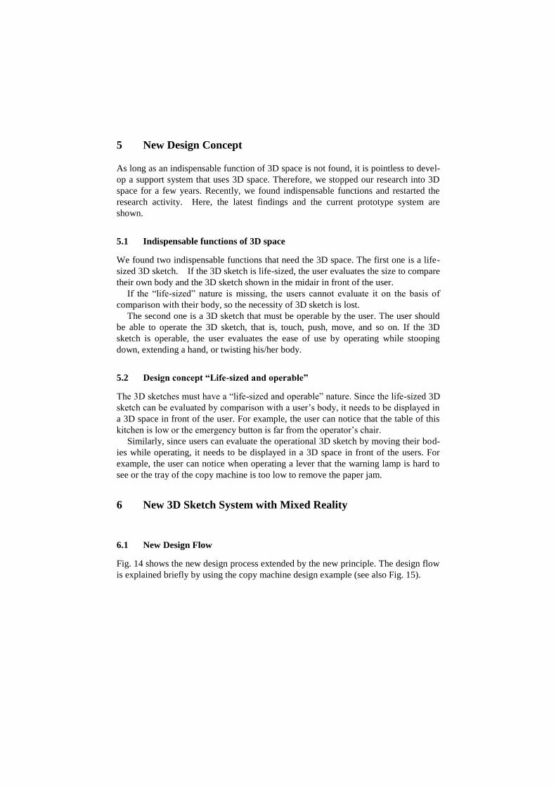
Fig. 14 shows the new design process extended by the new principle. The design flow
is explained briefly by using the copy machine design example (see also Fig. 15).
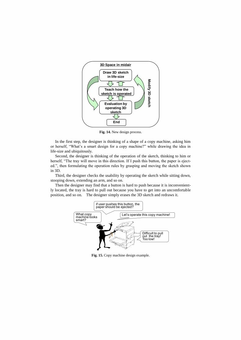
Fig. 14. New design process.
In the first step, the designer is thinking of a shape of a copy machine, asking him
or herself, “What’s a smart design for a copy machine?” while drawing the idea in
life-size and ubiquitously.
Second, the designer is thinking of the operation of the sketch, thinking to him or
herself, “The tray will move in this direction. If I push this button, the paper is eject-
ed.”, then formulating the operation rules by grasping and moving the sketch shown
in 3D.
Third, the designer checks the usability by operating the sketch while sitting down,
stooping down, extending an arm, and so on.
Then the designer may find that a button is hard to push because it is inconvenient-
ly located, the tray is hard to pull out because you have to get into an uncomfortable
position, and so on. The designer simply erases the 3D sketch and redraws it.
Fig. 15. Copy machine design example.
3D Space in midair
Mo
dify
3D
sketc
h
Draw 3D sketch
in life-size
Teach how the
sketch is operated
Evaluation by
operating 3D
sketch
End
What copy machine looks smart?
Difficult to pull out the tray!Too low!
if user pushes this button, the paper should be ejected?
Let’s operate this copy machine!
6.2 Examples of Design Process
Fig. 16 shows our other application field, i.e., the control room design. It is very im-
portant to design a usable control room from the safety point of view. It is impossible
to make a mock-up system due to the exorbitant costs. In a real design department, the
designers will design it virtually by using the 3D-CAD system. During the design
process, the designers cannot fully appreciate the size and operability. All they can do
is to imagine the size and the operation scene in their mind.
By using our latest prototype system, the designer starts to draw the control room
roughly (Fig.16 (a)). Then the designer teaches the system the operation of levers,
buttons, and warning lights (Fig.16 (b)). The designer finds several problems (Fig.16
(c)) and fixes them by redrawing the sketch (Fig.16 (d)).
Note that all this is done by hand-drawn sketches. The scenario can be done in less
than one hour.
Fig. 16. Control room design example.
6.3 Special User Interaction for the New Design Concept
The new design concept “life-size and operability” requires new interaction methods.
Let’s draw the control room roughly
Let’s teach that this lever move in
this direction.
Let’s teach the warning light flushes red when push this button
Let’s teach that this lever move in
this direction.
Let’s teach the warning light flushes red when push this button
Let’s move lever at the
middle of desk!
Let’s get together warning lights here!
(a) Initial Sketch (b) Operable Sketch
(c) Usability Check (d) Modification of Sketch
Oh, my hand cannot reach this
lever when seated!
Oh, when this button, I cannot look at the red warning light!
6.3.1 Interactions for “life-size”
Since it is difficult to draw a life-size image, our system has several unique interac-
tions. Here three interactions are shown.
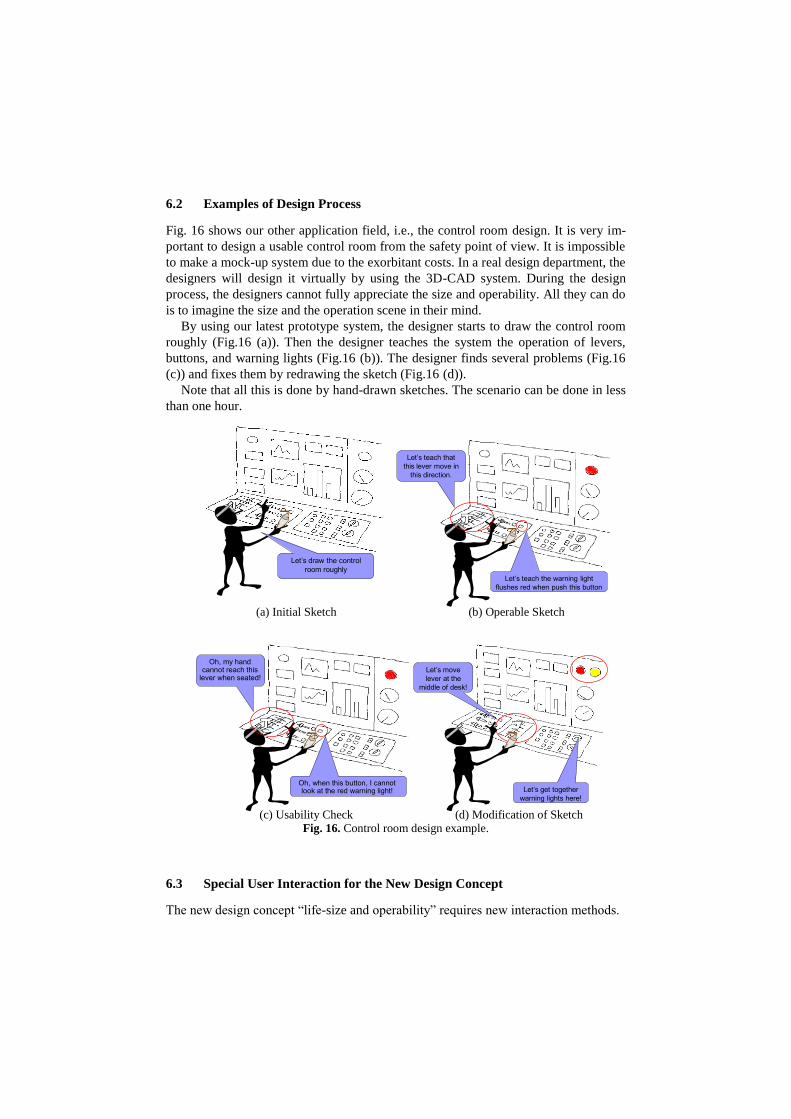
The color of the drawing line changes at the fixed length (50cm) as shown Fig. 17.
The designer can recognize the length of the line while drawing the lines.
Fig. 17. Line length notification.
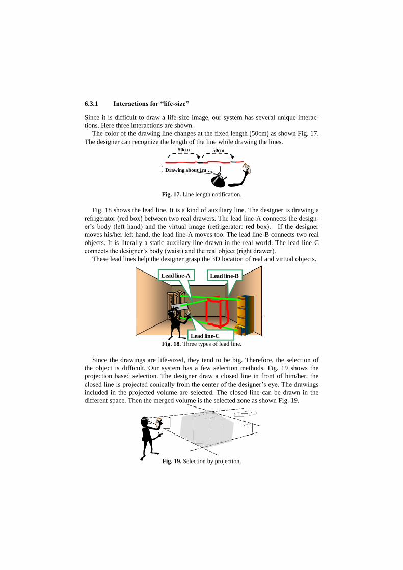
Fig. 18 shows the lead line. It is a kind of auxiliary line. The designer is drawing a
refrigerator (red box) between two real drawers. The lead line-A connects the design-
er’s body (left hand) and the virtual image (refrigerator: red box). If the designer
moves his/her left hand, the lead line-A moves too. The lead line-B connects two real
objects. It is literally a static auxiliary line drawn in the real world. The lead line-C
connects the designer’s body (waist) and the real object (right drawer).
These lead lines help the designer grasp the 3D location of real and virtual objects.
Fig. 18. Three types of lead line.
Since the drawings are life-sized, they tend to be big. Therefore, the selection of
the object is difficult. Our system has a few selection methods. Fig. 19 shows the
projection based selection. The designer draw a closed line in front of him/her, the
closed line is projected conically from the center of the designer’s eye. The drawings
included in the projected volume are selected. The closed line can be drawn in the
different space. Then the merged volume is the selected zone as shown Fig. 19.
Fig. 19. Selection by projection.
Drawing about 1m …
50cm 50cm
Lead line-B
Lead line-C
Lead line-A
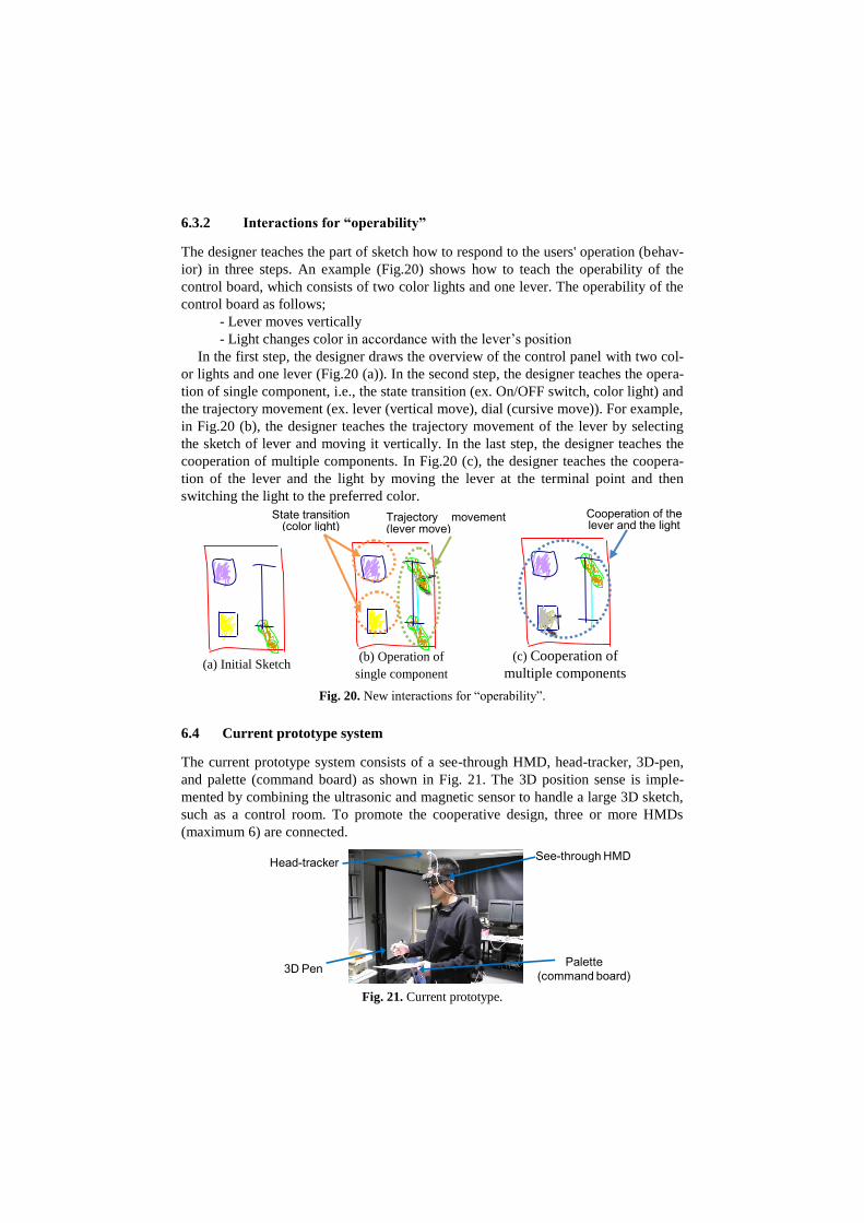
6.3.2 Interactions for “operability”
The designer teaches the part of sketch how to respond to the users' operation (behav-
ior) in three steps. An example (Fig.20) shows how to teach the operability of the
control board, which consists of two color lights and one lever. The operability of the
control board as follows;
- Lever moves vertically
- Light changes color in accordance with the lever’s position
In the first step, the designer draws the overview of the control panel with two col-
or lights and one lever (Fig.20 (a)). In the second step, the designer teaches the opera-
tion of single component, i.e., the state transition (ex. On/OFF switch, color light) and
the trajectory movement (ex. lever (vertical move), dial (cursive move)). For example,
in Fig.20 (b), the designer teaches the trajectory movement of the lever by selecting
the sketch of lever and moving it vertically. In the last step, the designer teaches the
cooperation of multiple components. In Fig.20 (c), the designer teaches the coopera-
tion of the lever and the light by moving the lever at the terminal point and then
switching the light to the preferred color.
Fig. 20. New interactions for “operability”.
6.4 Current prototype system
The current prototype system consists of a see-through HMD, head-tracker, 3D-pen,
and palette (command board) as shown in Fig. 21. The 3D position sense is imple-
mented by combining the ultrasonic and magnetic sensor to handle a large 3D sketch,
such as a control room. To promote the cooperative design, three or more HMDs
(maximum 6) are connected.
Fig. 21. Current prototype.
See-through HMD
Palette(command board)3D Pen
Head-tracker
(a) Initial Sketch
State transition (color light)
Trajectory movement (lever move)
Cooperation of the lever and the light
(b) Operation of
single component
(c) Cooperation of
multiple components
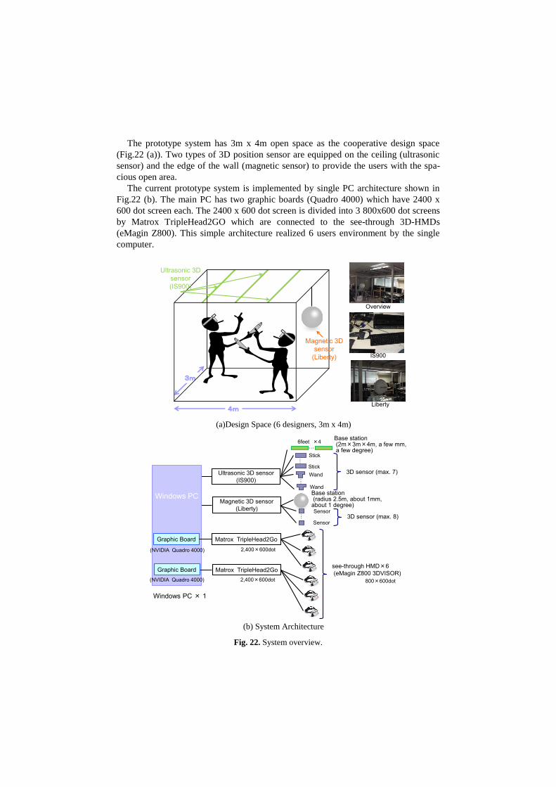
The prototype system has 3m x 4m open space as the cooperative design space
(Fig.22 (a)). Two types of 3D position sensor are equipped on the ceiling (ultrasonic
sensor) and the edge of the wall (magnetic sensor) to provide the users with the spa-
cious open area.
The current prototype system is implemented by single PC architecture shown in
Fig.22 (b). The main PC has two graphic boards (Quadro 4000) which have 2400 x
600 dot screen each. The 2400 x 600 dot screen is divided into 3 800x600 dot screens
by Matrox TripleHead2GO which are connected to the see-through 3D-HMDs
(eMagin Z800). This simple architecture realized 6 users environment by the single
computer.
(a)Design Space (6 designers, 3m x 4m)
(b) System Architecture
Fig. 22. System overview.
Overview
IS900
Liberty4m
3m
Ultrasonic 3D sensor(IS900)
Magnetic 3D sensor
(Liberty)
Windows PC
Windows PC × 1
Graphic Board Matrox TripleHead2Go
Matrox TripleHead2Go
Ultrasonic 3D sensor (IS900)
Magnetic 3D sensor (Liberty)
2,400×600dot
2,400×600dot
see-through HMD×6(eMagin Z800 3DVISOR)
800×600dot
…Base station(2m×3m×4m, a few mm,a few degree)
6feet ×4
Stick…
Stick
… Wand
Wand
3D sensor (max. 7)
Base station(radius 2.5m, about 1mm, about 1 degree)
Graphic Board
Sensor…
Sensor
(NVIDIA Quadro 4000)
(NVIDIA Quadro 4000)
3D sensor (max. 8)
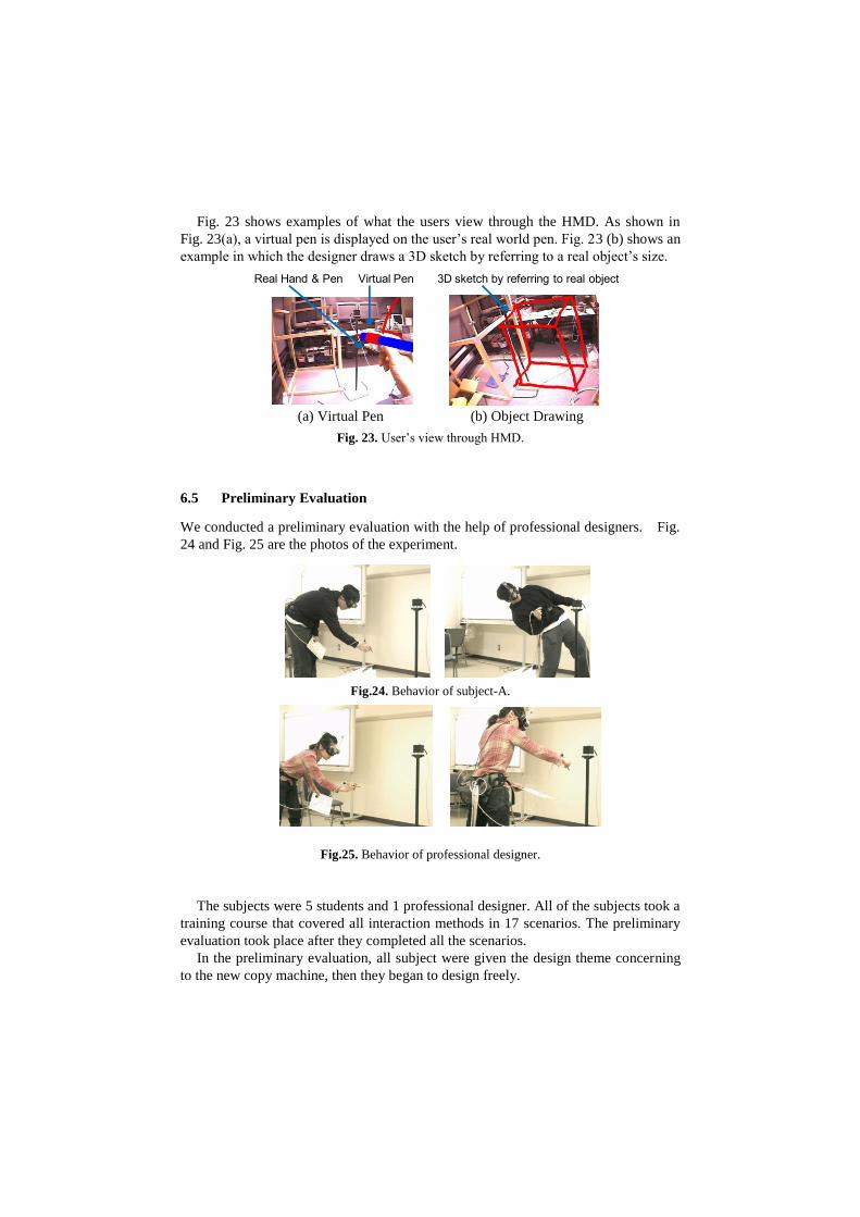
Fig. 23 shows examples of what the users view through the HMD. As shown in
Fig. 23(a), a virtual pen is displayed on the user’s real world pen. Fig. 23 (b) shows an
example in which the designer draws a 3D sketch by referring to a real object’s size.
Fig. 23. User’s view through HMD.
6.5 Preliminary Evaluation
We conducted a preliminary evaluation with the help of professional designers. Fig.
24 and Fig. 25 are the photos of the experiment.
Fig.24. Behavior of subject-A.
Fig.25. Behavior of professional designer.
The subjects were 5 students and 1 professional designer. All of the subjects took a
training course that covered all interaction methods in 17 scenarios. The preliminary
evaluation took place after they completed all the scenarios.
In the preliminary evaluation, all subject were given the design theme concerning
to the new copy machine, then they began to design freely.
Real Hand & Pen Virtual Pen 3D sketch by referring to real object
(a) Virtual Pen (b) Object Drawing
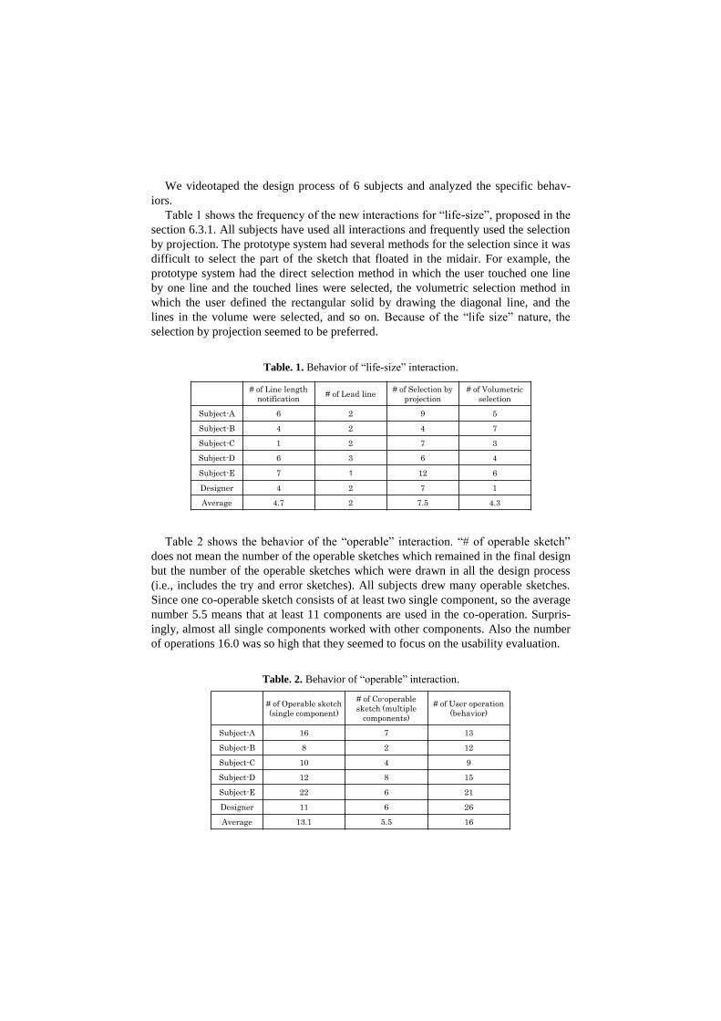
We videotaped the design process of 6 subjects and analyzed the specific behav-
iors.
Table 1 shows the frequency of the new interactions for “life-size”, proposed in the
section 6.3.1. All subjects have used all interactions and frequently used the selection
by projection. The prototype system had several methods for the selection since it was
difficult to select the part of the sketch that floated in the midair. For example, the
prototype system had the direct selection method in which the user touched one line
by one line and the touched lines were selected, the volumetric selection method in
which the user defined the rectangular solid by drawing the diagonal line, and the
lines in the volume were selected, and so on. Because of the “life size” nature, the
selection by projection seemed to be preferred.
Table. 1. Behavior of “life-size” interaction.
Table 2 shows the behavior of the “operable” interaction. “# of operable sketch”
does not mean the number of the operable sketches which remained in the final design
but the number of the operable sketches which were drawn in all the design process
(i.e., includes the try and error sketches). All subjects drew many operable sketches.
Since one co-operable sketch consists of at least two single component, so the average
number 5.5 means that at least 11 components are used in the co-operation. Surpris-
ingly, almost all single components worked with other components. Also the number
of operations 16.0 was so high that they seemed to focus on the usability evaluation.
Table. 2. Behavior of “operable” interaction.
# of Operable sketch
(single component)
# of Co-operable
sketch (multiple
components)
# of User operation
(behavior)
Subject-A 16 7 13
Subject-B 8 2 12
Subject-C 10 4 9
Subject-D 12 8 15
Subject-E 22 6 21
Designer 11 6 26
Average 13.1 5.5 16
# of Line length
notification# of Lead line
# of Selection by
projection
# of Volumetric
selection
Subject-A 6 2 9 5
Subject-B 4 2 4 7
Subject-C 1 2 7 3
Subject-D 6 3 6 4
Subject-E 7 1 12 6
Designer 4 2 7 1
Average 4.7 2 7.5 4.3
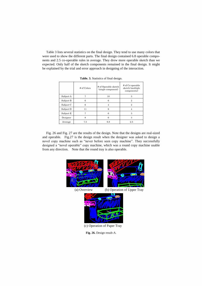
Table 3 lists several statistics on the final design. They tend to use many colors that
were used to show the different parts. The final design contained 6.8 operable compo-
nents and 2.5 co-operable rules in average. They drew more operable sketch than we
expected. Only half of the sketch components remained in the final design. It might
be explained by the trial and error approach in designing of the interaction.
Table. 3. Statistics of final design.
Fig. 26 and Fig. 27 are the results of the design. Note that the designs are real-sized
and operable. Fig.27 is the design result when the designer was asked to design a
novel copy machine such as “never before seen copy machine”. They successfully
designed a “novel operable” copy machine, which was a round copy machine usable
from any direction. Note that the round tray is also operable.
Fig. 26. Design result-A.
(a) Overview (b) Operation of Upper Tray
(c) Operation of Paper Tray
# of Colors# of Operable sketch
(single component)
# of Co-operable
sketch (multiple
components)
Subject-A 7 10 3
Subject-B 6 6 2
Subject-C 6 4 2
Subject-D 11 9 4
Subject-E 7 6 3
Designer 8 6 3
Average 7.5 6.8 2.5
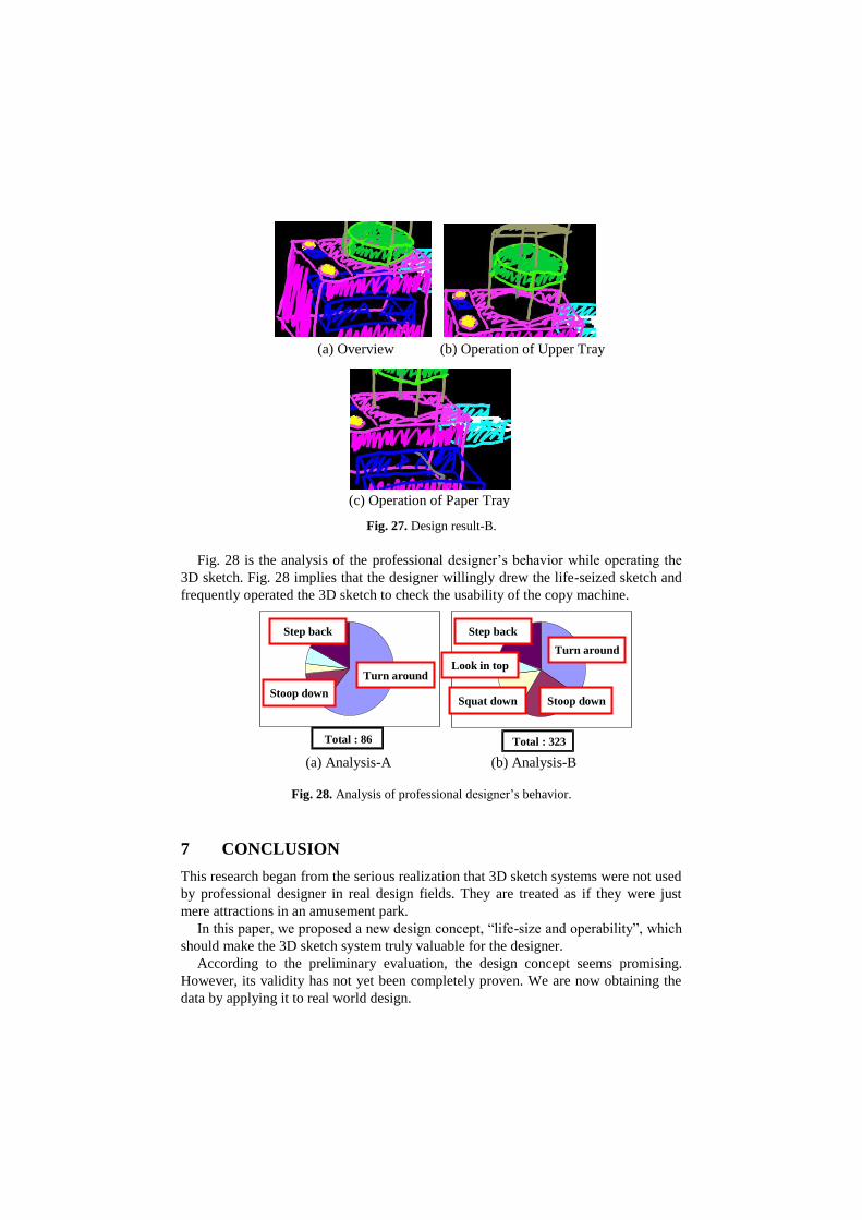
Fig. 27. Design result-B.
Fig. 28 is the analysis of the professional designer’s behavior while operating the
3D sketch. Fig. 28 implies that the designer willingly drew the life-seized sketch and
frequently operated the 3D sketch to check the usability of the copy machine.
Fig. 28. Analysis of professional designer’s behavior.
7 CONCLUSION
This research began from the serious realization that 3D sketch systems were not used
by professional designer in real design fields. They are treated as if they were just
mere attractions in an amusement park.
In this paper, we proposed a new design concept, “life-size and operability”, which
should make the 3D sketch system truly valuable for the designer.
According to the preliminary evaluation, the design concept seems promising.
However, its validity has not yet been completely proven. We are now obtaining the
data by applying it to real world design.
(a) Overview (b) Operation of Upper Tray
(c) Operation of Paper Tray
Total : 323 Total : 86
(a) Analysis-A (b) Analysis-B
Step back
Stoop down
Turn around
Turn around
Stoop down
Step back
Look in top
Squat down

We hope our research is helpful to design the multimedia-based support system for
professional use.
References
1. Dzulkhiflee, M., Tano, S., Iwata, M., Hashiyama, T.: Effectiveness of Annotating by Hand
for non-Alphabetical Languages, CHI-2006, pp. 841--850 (2006)
2. Iwata, M., Sasaki, Y., Tano, S., Hashiyama, T., Ichino, J.: A Sketch Support System Based
on Behavior of Designers, IEEE International Conference on Progress in Informatics and
Computing-2010, pp. 1298--1304 (2010)
3. Ichino, J., Makita, T., Tano, S., Hashiyama, T.: Support for seamless linkage between less-
detailed and more-detailed representations for comic design, CHI2009, pp. 3979-3984
4. Tano, Kamura, Iwata, Hashiyama: Digital Paper Concept for Reflective Writing by Seam-
less Traverse between Handwritten and Coded Information, HCI International 2005, E-
book (2005)
5. S. Tano: Quantitative Study on the Effectiveness of Pen-based Computing on Experiential
and Reflective Cognitive Modes, Mobile Computing in Education, pp. 46--49 (2009)
6. Tano, Kodera, Nakashima, Kawano, Nakanish, Hamagishi, Inoue, Watanabe, Okamoto,
Kawagoe, Kaneko, Hotta, Tatsuoka: Godzilla: Seamless 2D and 3D Sketch Environment
for Reflective and Creative Design Work, INTERACT 2003, pp. 131--138 (2003)
7. Tano, S., Komatsu, Y., Iwata, M.: Extended Godzilla: Free-form 3D-object Design by
Sketching and Modifying Seven Primitives at Single 2D-3D Seamless Display, APCHI-
2004, pp. 471--480 (2004)
8. Tano, Sugimoto: Natural Hand Writing in Unstable 3D space with Artificial Surface, CHI-
2001, pp. 353--354 (2001)
9. Tano, S., Matsumoto, T., Iwata, M.: Quantitative Analysis of Human Behavior and Im-
plied User Interface in 3D Sketching, APCHI-2004, pp. 481--490 (2004)
10. Wayne et al.: Interactive Augmented Reality Techniques for Construction at a Distance of
3D Geometry, Eurographics 2003, pp. 19--28 (2003)
11. Steven et al.: Surface Drawing: Creating Organic 3D Shapes with the Hand and Tangible
Tools, CHI 2001, pp. 261--268 (2001)
12. Gerols et al.: Free Drawer: A Free-Form Sketching System on the Responsive Workbench,
VRST’01, pp. 167--174 (2001)
13. Daniel et al.: A Fully Immersive 3D Artistic Medium and Interactive Experience, Proceed-
ings 2001 ACM Symposium on Interactive 3D Graphics, pp. 85--93 (2001)
14. Tovi et al.: Creating Principal 3D Curves with Digital Tape Drawing, CHI2002, pp. 121--
128 (2002)
15. Shin, H., Igarashi, T.: Magic canvas: interactive design of a 3-D scene prototype from
freehand sketches, GI'07, pp. 63--70 (2007)
16. Olsen, L., Samavati, F.F.: Stroke extraction and classification for mesh inflation, In Proc.
of SBIM 2010, pp. 9--16 (2010)
17. Perkunder, K., Israel, J.H., Alexa, M.: Shape modeling with sketched feature lines in im-
mersive 3D environments, In Proc. of SBIM 2010, pp. 127--134 (2010)
18. Tano, S., Yamamoto, M., Dzulkhiflee, M., Ichino, J., Hashiyama, T., Iwata, M.: Three De-
sign Principles Learned through Developing a Series of 3D Sketch Systems: “Memory Ca-
pacity”, “Cognitive Mode”, and “Life-size and Operability”, IEEE SMC 2012, pp. 880--
887 (2012)
Recommended