1
Proc.I.Mech.E. vol. 221 Part A. Journal of Power and Energy Special Issue paper pp.181195.
VerticalAxis TidalCurrent Generators and the Pentland Firth. Stephen Salter, Jamie Taylor.
Engineering and Electronics, University of Edinburgh. [email protected], [email protected]
Abstract
This paper extends ideas presented to the World Renewable Energy Conference [1] [2]. One idea involves the impedance of flow channels and its relevance to the maximum tidalstream resource. Estimates of the inertial and damping terms of the impedance of the Pentland Firth suggest a much higher resource size than studies based purely on the kinetic flux because adding extra turbines will have less effect on flow velocities than in a low impedance channel. This very large resource has pushed the design of the turbine towards the stream velocities, depth and seabed geology of this site. A second idea is an algorithm to control the pitch of closepacked verticalaxis generators to give an evenly distributed head. Finally there are suggestions for a seabed attachment aimed specifically for conditions in the Pentland Firth and intended to allow rapid installation of a selfpropelled tidalstream generator.
Keywords: verticalaxis turbine, tidalstream, marinecurrent generator, channel impedance, lowhead hydro, variablepitch, Betz momentum theory, Darrieus, troposkien, trilink, inflatable.
Backgound
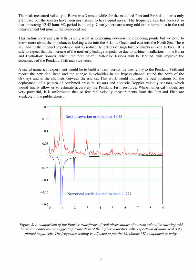
Field tests on verticalaxis turbines were first carried out by Fraenkel [3] who then abandoned the concept because of the difficulties of providing the necessary control of pitchangle. Pitch variation was an essential feature of the Edinburgh verticalaxis tidalcurrent generator which was first described at the 1998 European wave energy conference at Patras [4] and is shown in figure 3. The design had several layers of short blades with variable pitch. The layers were separated by elliptical section rings and cross braced by streamlined wires which gave torsional and shear rigidity. Power takeoff was above the surface and out at the rim, housed in a floating torus. It used a quad ringcam, variabledisplacement, highpressure oil pump to give the correct torque to convert from a variable input speed to the constant speed required by synchronous generators. The cam rollers could also perform the function of a geometrically tolerant bearing providing axial and radial location. The blade pitch was controlled only by the choice of a torque limit which allowed blades to adjust their own pitchangle above a chosen level of pitch torque so as to prevent stall. Mooring was by tension legs which passed through the centre of pressure of the rotor to avoid inducing pitching torque. However, tank tests showed that tension legs would suffer unacceptable snatch loads following any slackening, even in quite small waves.
Notation
Cf Bottom friction coefficient Cp Turbine performance coefficient L Channel length Pf, Pr Bed friction power or rotor power U Current velocity W Channel width Z Channel depth ρ Fluid density

2
Channel Impedance and the Pentland Firth
An important question for all tidal projects is the extent to which the introduction of generating plant will reduce the flow. We can think of this in terms of the impedance of the flow, a concept which is familiar to electrical engineers but less so to mechanical, marine and civil engineers even though there are many instances where it can be useful. One anthropomorphic way to think of impedance is as the determination needed for a current to overcome obstacles placed in its path. One of the extremes would be a source of constant current which has to flow and which will create whatever head (or voltage) is needed to overcome all resistances placed in its path. This is the tendency with long, shallow, rough flow channels where many banks of turbines might be installed in series up to some limit at which the increased upstream head would cause flooding. Less desirable would be the other extreme of a low impedance source where the flow could be stopped by an obstruction or easily find an alternative passage.
In electrical engineering the impedance of a source would be the ratio of the opencircuit voltage divided by the shortcircuit current. In a nonlinear device, like a zener diode, the local impedance could be obtained from the local slope of the current/voltage curve. For turbines we can calculate a resistive impedance from the turbine power divided by the square of flow rate through the turbine flow window or from the square of a water head divided by the power being generated. The effects of side channels could be calculated, just as in electrical network theory for series and parallel resistors.
Ratios of turbine power to bottom friction power are of particular interest. Consider a very simple case of steady flow in a channel of length L, width W, depth Z, and bottom friction coefficient Cf having a current velocity U of fluid density ρ completely filled with rotors having a performance coefficient of Cp.
The power at present being wasted by bed friction is Pf 1 2
ρ ⋅ W ⋅ L ⋅ U 3 ⋅ Cf ⋅ (1)
The power from a single full rotor bank would be Pr 1 2
ρ ⋅ W ⋅ Z ⋅ U 3 ⋅ Cp ⋅ (2)
By cancelling common terms, the ratio of the two is L Cf ⋅ Z Cp ⋅
(3)
If this ratio is unity, the power already being lost as bed friction will be equal to that of one bank of rotors filling the entire crosssection and we are on the edge of the change from a low to a high impedance channel. Note that the aeronautical engineers and turbine designers use the ½ for drag and power equations but oceanographers do not, and so care is needed in collecting values of friction coefficients.
A friction value of 0.017, has been measured at the Menai Strait by Campbell at al. [5]. If we use this in a very simplified model of the Pentland Firth with a channel length L of 23,000 metres, a depth Z of 70 metres and a turbine performance coefficient of 0.4, the LCf/ZCp ratio is 14 and so a channel of these dimensions is clearly a high impedance source. If the channel width was 10,000 metres, the seabed dissipation at a flow velocity of 3 metres per second would be 53 GW. Friction would be setting the flow velocity and many banks of turbines would reduce it only a little. Perhaps one third of 53GW could be captured giving an average output well above previous estimates [6].
The Pentland Firth has an irregular coast line, pits going to below 100 metres, shallows known as the Merry Men of Mey which generate eddies at the surface, a 30degree bend and two islands – Stroma and Swona – which must suffer large drag forces. The Menai friction coefficient of 0.017 is only four times more than that of a highly polished wing of a fighter aircraft at zero angle of incidence.
The velocities of tidal streams have been studied by Bryden [7], who has shown that they are more complicated, turbulent and variable than might be suggested by a first look at Admiralty tide tables. Work must be done to measure direction and velocity texture. There is also a need to measure impedance values in all flow channels and their side branches before making an accurate assessment of the tidal stream resource.

3
Measuring impedance
The drivingfunction of the tides depends on the skewness, noncircularity and precession of the orbits of the moon round the earth and their combined orbit round the sun. Further complications are that large masses of water attract one another by detectable amounts and that any nonlinearity caused by propagation in shallow water will make every component generate frequencies which are the sum and difference between its frequency and all the others. A useful listing of the components, periods and relative phases of 18 components for Delaware Bay is given in [8].
Thevenin’s theorem says that an electrical network of any complexity can be reduced to a single voltage source in series with a single impedance driving the load under study. The drive voltage would be whatever voltage would be present if the load under study were absent. Its analogy in water flows is the head difference that would be developed if a dam were built across the channel entry. The impedance in series with that head would be the total series/parallel combination of the other channels in the absence of the channel under study.
A measure of the impedance between two points in a channel could be calculated from measurements of the head difference at the points and the mean of their current velocities. The acoustic Doppler current profiler method [9] is excellent for measuring velocity and direction through the entire water column. Satellite measurements can give accurate measurements of changes of the mean level of large oceans but this requires many transits, and advice from Pugh [10] is that they would not give enough coverage over the Pentland Firth for the required resolution. His suggestion is to measure changes of head through the tidal cycle using bottommounted pressure transducers at a number of points along a channel over a period of a few months, together with simultaneous velocity measurements at the same points. Recently developed instruments combine both pressure and acoustic Doppler velocity measurements [11].
Before deciding on a programme of field measurements it is worth trying to make an approximate estimate. The simplest analysis would reduce a complex network of channels to three impedances. The first is the impedance which sets the flow induced by the astronomical forcing function from the Atlantic. This would be in parallel with the impedance of the parallel paths through and north of the Orkneys which can allow water to bypass the Pentland Firth. We know from [12] that there are quite large phase differences between tidal levels at the nearest observing stations at Kinlochbervie and Wick, so at least some of these impedances must have complex terms analogous to inductance and capacitance. Finally there is the impedance of the Pentland Firth itself. We know that the celerity of a long shallow water wave over a 70 metre bed would be 26 metres per second so it would take less than 15 minutes to travel along the full length. This seems very short compared with the 12.42 hour M2 tidal period and so it might be thought that the reactive terms ought not to be dominant.
The Proudman Laboratory has developed numerical tidal prediction software known as POL and kindly supplied their timeseries prediction of water level and velocity components for points at each end of the Pentland Firth [13]. The slope of the water surface could be calculated from the difference in head predictions. The eastward (conventionally known as U) component of velocity was almost the same at each end. The phase relationship of head to velocity was of particular interest. There are two ways to get an estimate. The easiest and crudest, suitable for engineers in a hurry, is to look at the times of zero crossings and assume that the records are wellbehaved sine waves. We generate a square wave using a logic statement that gives a value one if the head is positive and the velocity is negative or if the head is negative and the velocity positive. The markspace ratio of the square wave will give a measure of phase. For the main length of the Pentland Firth between 58°44'N 3°18'W and 58°42'N 3°9'W the zero crossing method gives a lag between head and velocity of 63 degrees.
A more respectable phase calculation, suitable for mathematicians, uses Fourier transforms. These carry all the information about each separate component of the spectrum. For each frequency the transform produces a real and imaginary number indicating the amplitude and phase of that component relative to a notional cosine wave of the same frequency with zero degrees referred to the beginning of the record.
4
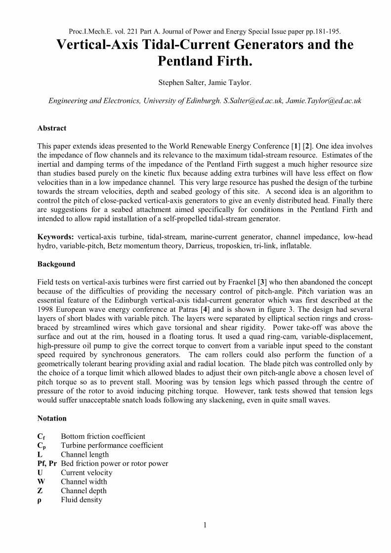
The ratio of the imaginary to the real amplitude at each frequency gives the tangent of the phase angle between the signal and the notional cosine wave. Repeating this for both head and velocity records gives the inertial and resistive parts of the channel impedance between the observation points. The technique can give spillage over into adjacent frequencies and so it can be useful to integrate over a short section of the frequency spectrum. Between the map coordinates given above, the phase lag between the head and the velocity of the strong M2 frequency as measured by this technique was 58.1 degrees. This is shown in the Lissajous plot of slope against the U component of velocity in figure 1.
Figure 1. A Lissajous plot of slope against easterly velocity at the ends of the Pentland Firth.
Based on the electrical analogy, this implies that, despite the short channelpropagation time, flow rates are defined by the inertia of the water in the Pentland Firth just as much by bed friction or the entry orifice. The installation of quite large numbers of turbines in several closepacked banks will change the phase of the velocity but not initially to the same extent as its magnitude, so there is a second reason to expect a higher resource than would be indicated purely from the present kinetic flux.
By dividing the differences between each sample in the Proudman velocity data by the time interval between them we can calculate the acceleration of the flow. The difference in head between two positions along the channel gives us the force that would have to be exerted by some very large, imaginary piston to produce the flow. As we know force and acceleration we can calculate a mass. For the Proudman Pentland data this mass, 2.7x10 13 kg, is about double what would have been calculated from length, depth and width. The reason for the increase is that any reduction in width or depth will need a higher local acceleration which will add to the requirement for the driving force and also the local kinetic energy.
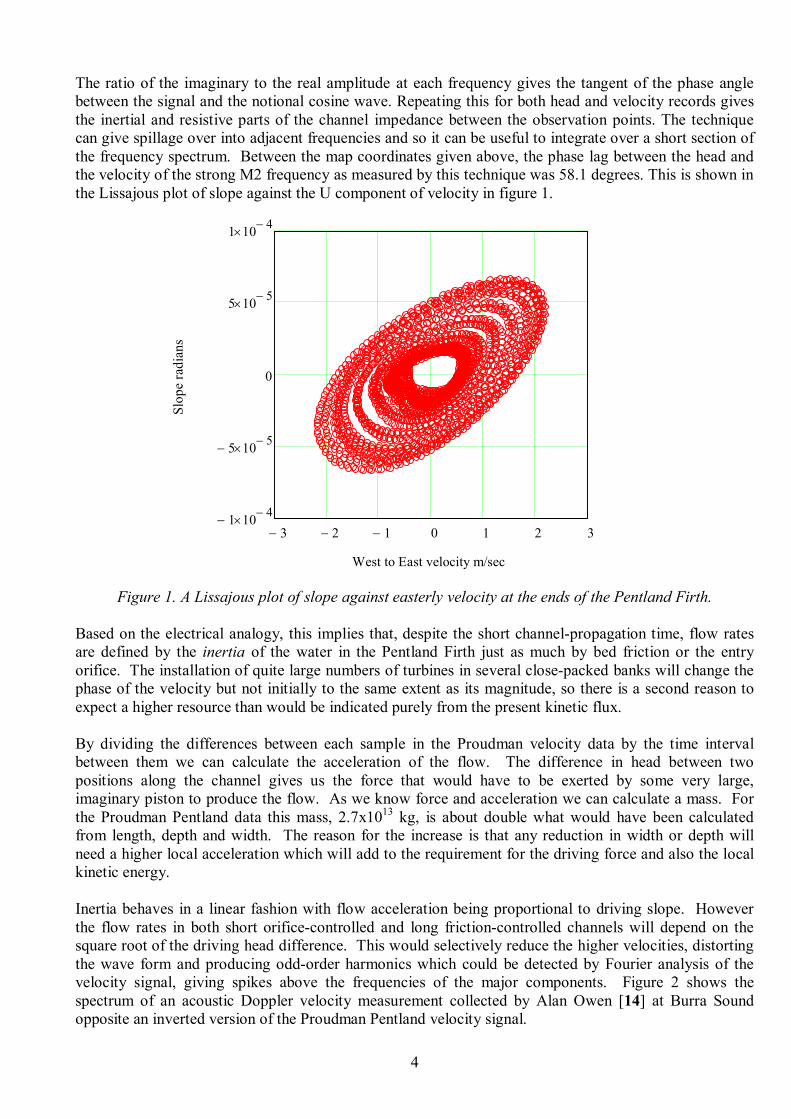
Inertia behaves in a linear fashion with flow acceleration being proportional to driving slope. However the flow rates in both short orificecontrolled and long frictioncontrolled channels will depend on the square root of the driving head difference. This would selectively reduce the higher velocities, distorting the wave form and producing oddorder harmonics which could be detected by Fourier analysis of the velocity signal, giving spikes above the frequencies of the major components. Figure 2 shows the spectrum of an acoustic Doppler velocity measurement collected by Alan Owen [14] at Burra Sound opposite an inverted version of the Proudman Pentland velocity signal.
3 − 2 − 1 − 0 1 2 3 1 − 10 4 − ×
5 − 10 5 − ×
0
5 10 5 − ×
1 10 4 − ×
West to East velocity m/sec
Slope radians
5
The peak measured velocity at Burra was 3 m/sec while for the modelled Pentland Firth data it was only 2.2 m/sec but the spectra have been normalised to have equal areas. The frequency axis has been set so that the strong 12.42 hour M2 period is at unity. Clearly there are strong oddorder harmonics in the real measurement but none in the numerical one.
This rudimentary analysis tells us only what is happening between the observing points but we need to know more about the impedances looking west into the Atlantic Ocean and east into the North Sea. These will add to the chennel impedance and so reduce the effects of high turbine numbers even further. It is safe to expect that the increase of the northerly leakage impedance due to turbine installations in the Burra and Eynhallow Sounds, where the first painful fullscale lessons will be learned, will improve the economics of the Pentland Firth and vice versa.
A useful numerical experiment would be to build a ‘dam’ across the west entry to the Pentland Firth and record the new tidal head and the change in velocities in the bypass channel round the north of the Orkneys and in the channels between the islands. This work would indicate the best positions for the deployment of a pattern of combined pressure sensors and acoustic Doppler velocity sensors, which would finally allow us to estimate accurately the Pentland Firth resource. While numerical models are very powerful, it is unfortunate that so few real velocity measurements from the Pentland Firth are available in the public domain
Figure 2. A comparison of the Fourier transforms of real observations of current velocities showing odd harmonic components, suggesting truncation of the higher velocities with a spectrum of numerical data plotted negatively. The frequency scaling is adjusted to put the 12.42hour M2 component at unity.
0 1 2 3 4 5 6 7 8 9 0.2 −
0.15 −
0.1 −
0.05 −
0
0.05
0.1
0.15
0.2
Real observation maximum at 1.018
Numerical prediction minimum at 1.221

6
Comparisons between Vertical and Horizontal Geometry
Although the horizontalaxis configuration is now universal for wind turbines, the verticalaxis configuration with rimdrive, faired rings between blade banks and crossbracing [2] shown in figure 3 may have some advantages for tidal streams and marine currents, especially in high impedance channels. The arguments are as follows:
The rectangular flow window of the verticalaxis rotor, particularly one where the rotor depth of individual machines can be tailored with additional layers of blades, can fill a large fraction of a channel crosssection. An evenly distributed pressure across closepacked contrarotating rotors will give lower wake turbulence. It will reduce the leakage between rotors and so may allow improvements in the performance coefficient above the Betz limit for a rotor in an open field.
The vertical axis allows a large diameter rotor, which would be stable in pitch and roll and which could be used in either deep or shallow water and allow power ratings of tens of megawatts.
By keeping velocity high, the full diameter rimdrive reduces powerconversion forces.
For a given foil velocity, a larger diameter will have a longer rotation period and so will suffer fewer fatigue cycles and will make lower torque demands on the pitchdrive system needed for accelerating the inertia of the blades and the added inertia of the water around them.
Rotors can generate from flows from any direction, even in turbulent flows which vary round the rotor circumference and through the depth of the channel. Banks of separate short blades would allow operation with the right pitch angle in deep water with a large velocityshear.
In the event of an electrical fault on land, generation can be stopped instantly with no actuator power by releasing all the foils to head into the local flow direction.
In the highest spring tides and unforeseen surges, pitch angles can be reduced to shed power and avoid upstream flooding.
The rings that support blades at both ends reduce bending moments by a factor of four relative to cantilevered blades and thus ease the task of the bearings needed for variablepitch.
The bottom ring can reduce tip vortices and give flow augmentation equivalent to longer blades.
The rings can house pitch actuators and the bottom ring can contain airbags, which can be inflated to lift the entire structure clear of the water for inspection or for the removal of biofouling.
Generation plant can be easily accessible in the dry and can even be inspected during operation.
Blades can have a constant crosssection, giving cheap tooling and perhaps extrusion.
With internal fuel tanks, Diesel power and fast pitchvariation, rotors can become agile, selfpropelled vessels like tugs equipped with VoithSchneider propellers [15].
The most common objection to the verticalaxis configuration with fixedpitch has been that the velocities of blades moving upstream are higher than those of blades moving downstream. This leads to uneven power production across the flow window with a risk of stall for part of the rotation and insufficient lift for another part. However, with a sophisticated pitchcontrol this problem can be entirely overcome. It could be argued that the velocity compromises are less than those arising from the difference between hub and tip velocities in a horizontalaxis machine.
Wind turbine designers like high tipspeed ratios (five or more) because the requirement for torque in the blade roots, shaft and gearing is inversely proportional to it. Torque, especially in gears, is expensive. The limits to high tipspeed ratios are set by increased noise and that, above some critical speed, there is a sharp rise in the damage from impacts with rain drops. The torque argument would also apply to rotors working in water. However the droplet erosion effect is replaced by the much more serious effect of cavitation. Even if we choose foil sections with low pressurecoefficients given by large radii of curvature at the nose, tipspeed ratios will be 2.5 or less in the highest current velocities.
7
Figure 3. An artist’s impression by Carn Gibson of the first ideas for the Edinburgh vertical axis turbine.
A Pitch Control Algorithm for ClosePacked Rotors
The Betz theory [16] for optimal performance of wind turbines in an open flow field requires that the momentum of the flow through a rotor should be reduced by twothirds of the upstream value by its passage through the rotor. Strictly this should apply to all points across the swept disk. But as there is a strong reduction in blade velocity towards the hub of horizontalaxis machines, a compromise has to be reached with respect to higher chords and increased pitch angles near the hub. The same momentum requirements will apply to verticalaxis wind turbines except that the compromise is in the change of relative velocity across the window.
With verticalaxis marinecurrent turbines which operate at the surface, the situation is slightly different because water cannot flow over the machine. If they are part of a closepacked array, water will not be able to flow easily round the sides. If they occupy a fairly large fraction of the water depth then it will not be easy for the water to flow beneath. This means that the performance coefficient of large marine current systems should be able to exceed the Betz limit. However as this will not be the case for the very first installations it is useful to consider the Betz design criterion.
We start with the assumption that the momentum objective has been achieved and that the water velocity through the entire rotor window is twothirds of the distant upstream value. While it is passing through the rotor the water must experience a force that will reduce its momentum to 1/3 of the original value. The volume of water must be conserved while it is within the swept volume of the rotor. According to the Bernoulli equation there will be an abrupt loss of head going through both the upstream and downstream arcs of the rotor followed by a slow recovery along the wake.
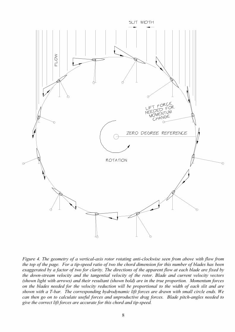
For this analysis we replace the stream tubes used by Strickland [17] for the troposkien blades of the Darrieus ‘eggbeater’ wind turbines with vertical stream slits. These are drawn in figure 4, where the slit boundaries are defined by points at equal angles round the circumference of the rotor. This implies that the time taken for a blade axis to pass through a slit is constant. (An analysis using slits of equal width is also possible.) We assume that the reduction in flow velocity starts some appreciable distance upstream, that the velocity through the rotor is twothirds of the upstream velocity and that the reduction to onethird is complete at some long distance downstream.
8
Figure 4. The geometry of a verticalaxis rotor rotating anticlockwise seen from above with flow from the top of the page. For a tipspeed ratio of two the chord dimension for this number of blades has been exaggerated by a factor of two for clarity. The directions of the apparent flow at each blade are fixed by the downstream velocity and the tangential velocity of the rotor. Blade and current velocity vectors (shown light with arrows) and their resultant (shown bold) are in the true proportion. Momentum forces on the blades needed for the velocity reduction will be proportional to the width of each slit and are shown with a Tbar. The corresponding hydrodynamic lift forces are drawn with small circle ends. We can then go on to calculate useful forces and unproductive drag forces. Blade pitchangles needed to give the correct lift forces are accurate for this chord and tipspeed.

9
Optimum pitch angle calculation steps
1. We know both the width of each slit and the ideal flow velocity and so we know the mass flow through it. It may help to think of the water as a long train moving through the rotor window.
2. The tangential velocity of the blades will have been chosen with cavitation in mind. For each slit, we know the direction and magnitude of the resultant velocity that would be seen by an observer riding on a blade.
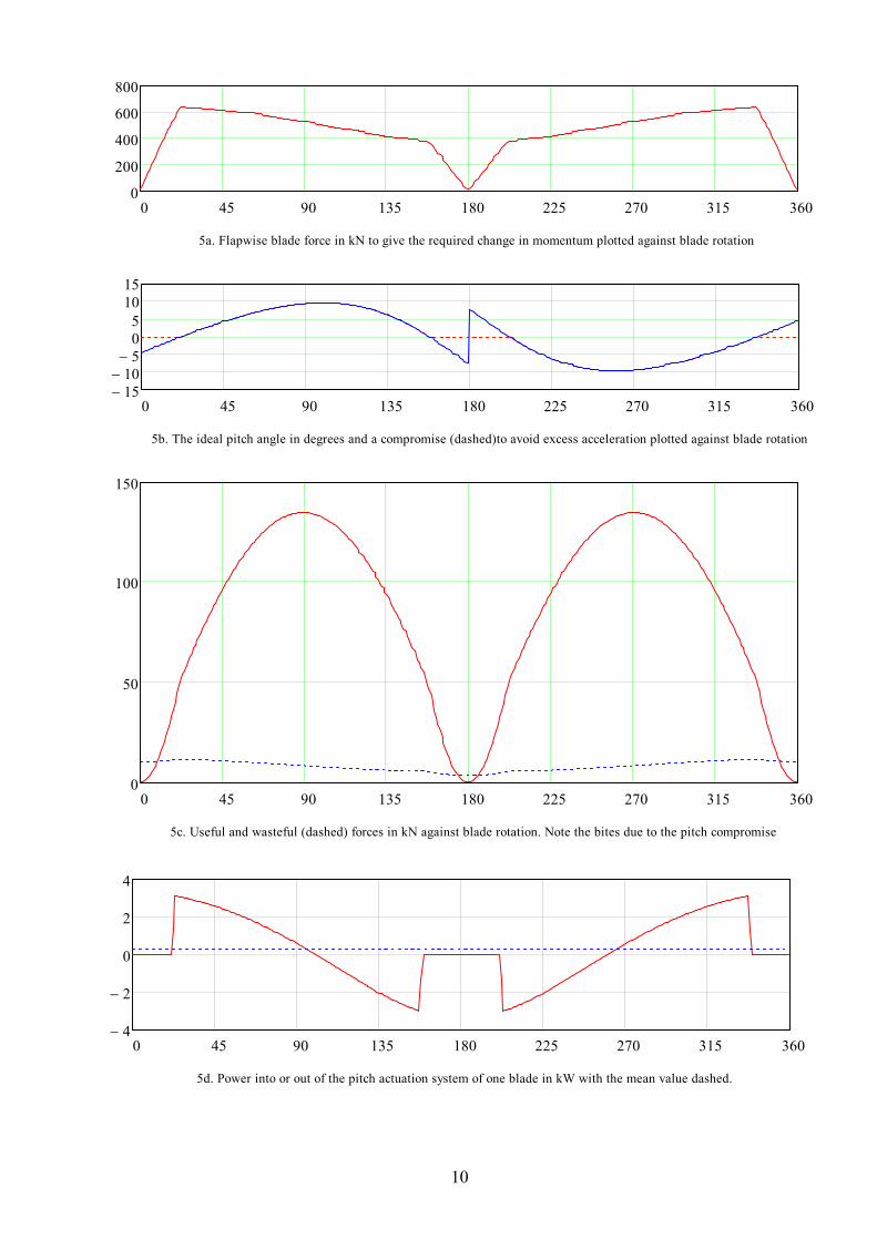
3. We know that in each slit the component of force acting on the water in the upstream direction should produce the desired twothirds reduction in momentum for that mass flow. With close packed rotors in high impedance channels we can choose the force which will give the same chosen head across the rotor diameter. This is plotted in figure 5a.
4. We know that this force must be a component of the hydrodynamic forces on the blades moving through the slit and that, if the blades are not stalled, it will be nearly perpendicular to the direction of the resultant velocity on the blades. More accurately, it will be inclined from that direction towards the trailing edge of the foil by a small angle whose tangent is the ratio of lift to drag. Away from stall this angle will be very small, less than one degree.
5. If we know the angle between this resultant force and the upstream direction we can calculate the magnitude of the hydrodynamic force that would have the right upstream component from blades in that slit.
6. We can also calculate the crossstream component of the force which will allow the calculation of the change of direction of the flow through an isolated machine or the change of head between rotors in a closepacked array of contrarotating turbines where the direction changes are prevented.
7. There will not always be blades in a slit but we can calculate the fraction of time that any blade axis will be in a given slit. We can therefore calculate what the blade forces should be by dividing the slit force by the fraction of occupancy.
8. If we know the blade chord and the resultant velocity on a blade in any slit we can calculate the Reynolds number for that slit and so look up the appropriate lift and drag coefficients. For known lift and drag, a given choice of blade chord and knowledge of the magnitude of the resultant water velocity at any slit, we can calculate the angle of incidence that a blade in a slit should have to the local resultant velocity. For isolated turbines we can add the addition angle needed to allow for flow divergence. The variation of pitch angle through a rotation cycle for one design case of a closepacked machine is shown in figure 5b. This includes a compromise to avoid excessive angular acceleration of the blade inertia. Note that the position of maximum pitch angle comes slightly later than the angle to the upstream direction.
9. We can then calculate the useful component of the force driving the turbine and subtract the drag on the foil rings and crosswires. Knowing the useful force and the blade speed we can calculate the efficiency, the output power and the torque which would have to be provided by the power conversion mechanism. The contribution to the power of one blade through a full rotation is shown in figure 5c. Note the bites resulting from the pitch compromise. These lose about 1%.
For figure 5 the lift and drag coefficients of a NACA 0018 foil were taken from Hanley Innovations MultiElement software [18]. A 140 metre diameter rotor would have 20 blades per bank with 2.3 metre chord and 11 metre span and a tipspeed ratio of 2.5. The openstream velocity of 3 metres per second would generate 11.3 MW per bank. Reynolds number would be 7.6 million.
10
0 45 90 135 180 225 270 315 360 0
200
400
600
800
5a. Flapwise blade force in kN to give the required change in momentum plotted against blade rotation
0 45 90 135 180 225 270 315 360 15 − 10 − 5 − 0 5 10 15
5b. The ideal pitch angle in degrees and a compromise (dashed)to avoid excess acceleration plotted against blade rotation
0 45 90 135 180 225 270 315 360 0
50
100
150
5c. Useful and wasteful (dashed) forces in kN against blade rotation. Note the bites due to the pitch compromise
0 45 90 135 180 225 270 315 360 4 −
2 −
0
2
4
5d. Power into or out of the pitch actuation system of one blade in kW with the mean value dashed.

11
Results
These steps have been implemented as a Mathcad worksheet, which allows easy variation of all design variables with instant calculations of the results for optimum pitch angles, forces, torques, cavitation pressure, efficiency and power. It gives structural weights for any choice of working stress and costs for any chosen cost per weight.
The mean drag power from the rotor blades reduces output by 4.5% of the ideal Betz figure. The drag from the diagonal ties (shown in figure 7) with streamlined fairings would reduce it by about 1% and the skin drag of unfouled rings by a further 2.5%. The drag loss of the lower ring is likely to be less than that from the tip vortex, which it suppresses. In combination these give an estimated performance coefficient of 0.51. This coefficient should apply across a wide range of solidities flow velocites and tipspeed ratios provided that the appropriate pitch control is used.
It was reassuring to note that, if all the drag coefficients are set to zero, the MathCad model predicts a performance coefficient very close to the 16/27 figure of a perfect Betz rotor. Halving the value of the drag coefficient improves the performance coefficient by 3% The addition of a blade pitcherror of one degree reduces the performance coefficient by less than 0.2% indicating a wide plateau of good operation.
At an open stream flow of 3 metres per second the prediction for the head difference across the turbine is 0.4 metres. Closepacked units filling most of the flow window in high impedance channels will behave more like turbines in ducts and so the Betz limit will not be applicable. With more blades or larger chords the performance coefficient should reach about 0.75.
There is a wide range of equally good choices of blade number, blade chord and tipspeed ratio with just two design boundaries. The first boundary is that the angle of incidence is never above the stall angle at any point of the rotation. If stall were to arise then the chord or number of blades would have to be increased so as to allow a smaller angle of incidence for the same force. We can therefore choose the number and chord so that we approach, but do not exceed, the stall angle. Higher numbers make for a good structural truss. Higher chords give blades that have good beam strength and so can be lighter than slender blades. It might be helpful to keep foil chords low enough for transport in sea containers.
The second design boundary requires that no point on any blade ever experiences a negative pressure coefficient high enough to induce cavitation. Pressure coefficients depend on the curvature of the foil at the nose, its angle of incidence and the magnitude of the resultant velocity. Fortunately the highest velocities are associated with small angles of incidence. Cavitation can be reduced somewhat by modified nose curvature, lower tipspeed ratios or the use of larger chords, which need smaller angles of incidence to produce the required forces. For this set of design choices the worst cavitation pressure was 73 kilo Pascals on a blade at 24.5 degrees from the crosscurrent diameter into the upcurrent sector.
In the case of an isolated rotor there will be the extra complication that the upstream foils will induce a change of flow direction, giving a diverging fanlike flow. However the effect of this will be to change the angles of incidence to the downstream blades by a predictable amount and so will be easy to correct. A likely installation scenario is that a rotor would be first installed and operated as an isolated machine and later joined by close neighbours, which will counter the diverging flow. Rotors at the end of a row will experience increased flow velocities but these will be reduced when there are enough banks built in series to give an impedance which approaches the channel value. Rotors may also have to be removed from time to time with effects on the pitchcontrol strategy of those on either side of the gap. All these considerations point to the need for retrospective modifications of the pitchcontrol algorithms.
12
Pitch actuation
Advanced algorithms for pitch control require a suitable pitch actuator. If the foil bearings are placed forward of the centre of pressure there will be a pitching moment tending to bring the blade noses in to the resultant velocity. For more than half the rotation period the required movement of the foil is in the same sense as the hydrodynamic torque on it, so blade pitch movement will be generating rather than absorbing power. Figure 5d shows the instantaneous power to or from one blade actuator through one cycle of rotation together with the mean output. The power output could be increased by moving the blade pitch axis nearer to the nose.
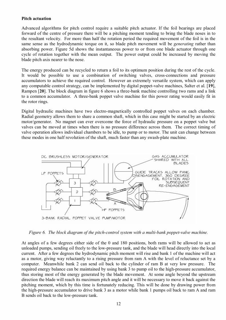
The energy produced can be recycled to return a foil to its optimum position during the rest of the cycle. It would be possible to use a combination of switching valves, crossconnections and pressure accumulators to achieve the required control. However an extremely versatile system, which can apply any computable control strategy, can be implemented by digital poppetvalve machines, Salter et al. [19], Rampen [20]. The block diagram in figure 6 shows a threebank machine controlling two rams and a link to a common accumulator. A threebank poppet valve machine for this power rating would easily fit in the rotor rings.
Digital hydraulic machines have two electromagnetically controlled poppet valves on each chamber. Radial geometry allows them to share a common shaft, which in this case might be started by an electric motor/generator. No magnet can ever overcome the force of hydraulic pressure on a poppet valve but valves can be moved at times when there is no pressure difference across them. The correct timing of valve operation allows individual chambers to be idle, to pump or to motor. The unit can change between these modes in one half revolution of the shaft, much faster than any swashplate machine.
Figure 6. The block diagram of the pitchcontrol system with a multibank poppetvalve machine.
At angles of a few degrees either side of the 0 and 180 positions, both rams will be allowed to act as unloaded pumps, sending oil freely to the lowpressure tank, and the blade will head directly into the local current. After a few degrees the hydrodynamic pitch moment will rise and bank 1 of the machine will act as a motor, giving way reluctantly to a rising pressure from ram A with the level of reluctance set by a computer. Meanwhile bank 2 can send oil back to the cylinder of ram B at very low pressure. The required energy balance can be maintained by using bank 3 to pump oil to the highpressure accumulator, thus storing most of the energy generated by the blade movement. At some angle beyond the upstream direction the blade will reach its maximum pitch angle and it will be necessary to move it back against the pitching moment, which by this time is fortunately reducing. This will be done by drawing power from the highpressure accumulator to drive bank 3 as a motor while bank 1 pumps oil back to ram A and ram B sends oil back to the lowpressure tank.

13
The electrical machines are needed to perform as motors only for the initial start. They can be a mix of DC brushless and AC induction types. Once the system is running they can be used to generate power for control logic, instrumentation, communications, hydrostatic bearings, compressors for inflating air bags which can lift the rotor clear of the water, dolphin repulsion, antifouling or cathodic protection. The direct connection of the two rams to the lowpressure tank can be used as a failsafe panic measure. In this condition the blades will move to align with the local flow whatever its direction, and there will be no lift and very low drag. This is useful for towing to site and for installation. It also provides a way to disconnect the power input that is faster, cheaper and more reliable than any braking system and that would be needed following any loss of the network connection.
The seabed attachment
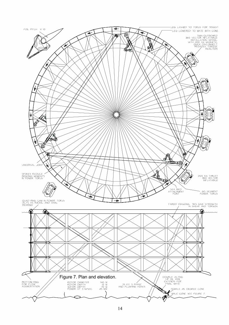
The seabed attachment affects the entire design of tidal stream turbines and is highly dependent on local geology. For a verticalaxis rotor we can use a system known as a trilink which consists of three rigid legs with spherical endbearings. These are shown in plan and elevation in figure 7. This will give the rotor freedom to heave, pitch and roll but will prevent surge, sway and yaw. Good tidalstream sites, which are open at both ends, are likely to be swept clear down to solid rock or very large boulders. However, closed estuaries such as Morecambe Bay will have thick layers of mobile sediment. An even more difficult seabed would be loose sediment containing large boulders or rock outcrops and the worst would be loose sand containing obstructions like abandoned trawling gear or mines. In two wars Britain and Germany deployed 600,000 mines. Only 180,000 have so far been accounted for. Many will have been put near Scapa Flow, close to promising tidal stream sites. A thorough survey with seabed penetrating radar is indicated.
For the easiest case of good rock the preferred choice, shown in figures 7 and 8, is a set of three conical fabrications pulled down into a conical crater by posttensioned steel strands protected from corrosion by alkaline grout. The size of the cone is set by the strength of the rock. For the Pentland Firth the seabed rock is red sandstone with a bending strength in the plane of the strata of 37 MPa. With a maximum stress of 10 MPa and the prestress factor of 0.4, the diameter of a 60 degree cone for a 60 MW rotor would be 4 metres. Cones can be made of Corten (a corrosionresistant but easily weldable steel) with an antifouling treatment.
The conical holes in the rock would be produced by equipment mounted on a Bryden Sea Snail [21], a novel seabed vehicle, which gains its downthrust from the water flow and has proved to be much more effective than clump anchors. The snail would be fitted with a rock drill which can be inclined at 60 degrees to the horizontal and also rotated about the vertical axis. This would produce a ring of inclined holes which would nearly meet at the centre. These would be filled with explosives. A ring of low energy propellant will produce a bubble curtain to contain the effects of the blast. A similar method can clear debris from the crater.
The outer surface of the lower cone slope would be fitted with stiffeners in the form of lengths of angle iron. They will initially be filled with clay and will later form passages for posttensioning tendons. Across the cone would be a conical socket, set at an angle to be perpendicular to the mooring leg. The weight of steel would be about 12 tonnes. A float on the top of the cone would give it enough buoyancy to allow placement with an inflatable vessel. The float would be released, and concrete weighing about 20 tonnes would be pumped inside the cone and in the rough spaces between the cone and the surrounding blastcrater in the rock. The total weight will keep the cone and additional tooling in place.
Drilling holes and placement of posttensioning tendons can be done with a robotlike machine which can sit on the upper cone and be indexed about its vertical axis. A ring of 45 holes will be drilled through the clay in the angleiron stiffeners and then a further 20 metres into the bed rock. Eight lengths of 50 mm diameter, 3metre drill tube will be held in a rotating can like the chamber of a revolver. It would be sequentially fed downward at 30 degrees from the vertical and returned to the can when the hole has reached full depth. A design for this machine will be presented in a future paper.
14
Figure 7. Plan and elevation.
15
TOP VIEW
33 KV CO
NTAC
TS
X 5 SC
ALE
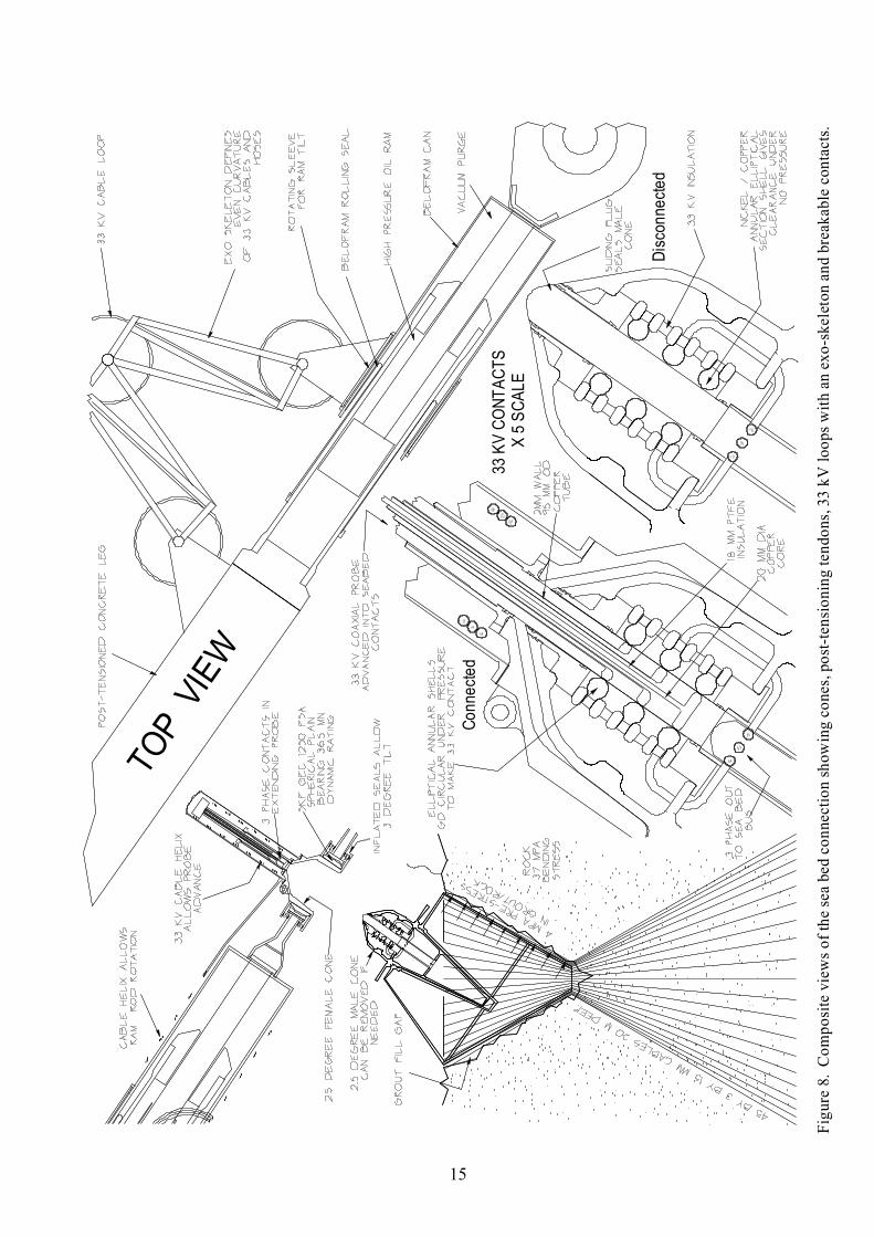
Figure 8. Com
posite views o
f the sea bed connection show
ing cones, posttensioning tendons, 33 kV loops w
ith an exoskeleton and breakable contacts.
Connected
Disconnecte
d

16
A plastic hose on the indexing head will be fed down to the bottom of the holes and grout pumped in to the bottom threequarters of the depth of each hole. The rest of the hole and the passages through the cone will be filled with a nonsetting alkaline, hydrophobic, conformable paste, perhaps based on lithium grease, with a density above that of sea water. The nonadhesion of the top quarter of the tendon above the grout level is desirable to store elastic energy and maintain a constant tension to avoid fatigue.
The tendons would be 15mm diameter, sevenstrand wire. This can safely be wrapped round and paid out from a 3.5 metre diameter drum but this wire diameter is rather small for a rock drill hole. Three strands will be passed into each of 45 holes drilled to 50 mm diameter. The odd number means that the holes will miss each other. The final tool on the indexing head will crop the strands, place a triplex collet over their ends, pull them to the working tension and finally fit a protective cap. This complex tool will require advanced robotic techniques but its cost can be written off over many hundreds of installations.
When a leg is in compression the typical maximum force of about 20 MN from a 45 MW rotor will go safely straight down into the rock and increase the compressive stress at the conetorock interface. When a leg is in tension the holddown force must exceed the vertical component of the leg tension which could reach 14 MN. The system has the same features as a posttensioned concrete structure and the upward force is supplied by a reduction of the compressive stress between cone and rock. This contact has much less elasticity than the long tendons and so the tendon stress remains constant and fatigue is avoided. Furthermore all tendons will have been fully tested during the posttensioning process before the turbine is installed.
The lower end of each leg, shown in figure 8, will be fitted to the cylinder of a large hydraulic ram. The rod of the ram will be fitted to the outer of a plain spherical bearing such as the SKF GEC 1250 FSA [22]. This has a dynamic rating of 35.5 MN and a static rating of 52 MN. It can take rotation of 3 degrees either side of centre. The pressure in the ram will be an accurate measure of the force on the leg. If oil from each side of the ram piston is fed to the appropriate side of the bearing it can partly offset the contact force without going all the way to the higher leakages of a full hydrostatic bearing. The small exit flow from the bearing must be scavenged and returned to the system.
The inner of the plain bearing will carry a female cone with a 45degree half angle which turns into a much more acute angle, probably 2.5 degrees. The choice of this angle is important because it will form the contact with a male cone permanently placed on the seabed. The axes of the cones will lie perpendicular to the direction of the leg. The female cone will contain a set of reinforcedtextile airbags made of a material similar to that used for fire hoses. These will act as cushions when inflated but will vent air and slowly collapse as the cones approach one another. The outer end of the female cone will be bellmouthed.
Installation
Conventional marine installation uses tugs and towlines. An inelastic cable connecting two objects which are far enough apart to be in waves of opposite phase can experience a tension which is the relative separating acceleration (possibly twice the acceleration of the water in a wave) times the mass plus added hydrodynamic mass of the lighter object. Even higher tensions can result if a cable is allowed to go slack and then retighten after the buildup of kinetic energy. An elastic cable can store energy which will be half the square of the peak tension times the spring rate of the rope. If the cable should ever break it will release this stored energy in a frighteningly short space of time.
Cables can apply only tension and in only one direction. They are slow to make changes in that direction. To connect or disconnect heavy cables at sea requires intelligent communication and the control of large forces and heavy objects at both ends of the cable, but vessels in distress often have no power to move heavy objects and sometimes not even a crew. The only attractive things about a cable are that the tug can be at a safe distance from a dangerous client vessel which is burning or about to explode and that the cable can be coiled for compact stowage. Everything else about towing cables is bad.

17
Conventional tugs must be able to make transocean crossings lasting many days in any weather and must provide acceptable living conditions for quite large crews. This makes hire expensive, typically tens of thousands of pounds a day for an unpredictable number of days. Furthermore availability and hire costs vary widely depending on weather, demands of other work and the location of the tug. The vessels have to be paid for as they move between jobs and when they have no work. Until the oil has gone, the marine renewables cannot compete with the charter prices of oil firms. A single installation cycle can be a large fraction of initial capital cost and early devices may need many cycles of removal and reinstallation.
A better system would place the tug and the structure being towed close enough to be in the same wave phase and arrange that their phase and amplitude responses to wave spectra are similar. This would produce a large reduction in the forces between them. The driver vessel should be able to apply force in any direction through a short connecting link and change it quickly. The system should allow instant connection and disconnection with intelligence at only one place and no need for handling heavy weights.
The drag of a hydrofoil at zero angle of incidence is about onefortieth of the drag of a circular cylinder which would just fit inside it. If the rotor foils are free to point into the direction of the local water velocity, turbines will be quite easy to tow. However with fuel and a Diesel engine on board, a pair of verticalaxis rotors could act like oceangoing vessels with an astonishing bollard pull and extreme agility in any direction. A single rotor could do quite well if fitted with some torque reaction. An installation vessel using very large inflated tubes, GPSlinked 360degree variablepitch vectorthrusters and a quick disconnect magnetic coupling has been described [23]. Each can produce a thrust of 200kN so a group of four could install a large rotor, even without assistance from the rotor itself.
Before the installation one inflatable vessel will arrive at the site, where there will be three marker buoys with lines running down to caps protecting the male cones on the seabed. The buoys will be captured and their lines will be made fast to the vessel. The lines will contain air hoses leading to the inside of the caps so that they can be released by compressed air. Device arrival will be timed for just after the seabed conecaps have been removed. The turbine will be accurately positioned over its designated site with help from a carrierphase differential GPS navigation system. Analysis of records from acoustic Doppler instruments shows that several sites never have completely slack water but rotors can ‘hover’ accurately enough for the lower ends to make connection with the seabed attachment points.
When the rotor has reached approximately the correct position and the support vessels have rotated it to the correct azimuth angle, the legs can be lowered by partial filling with water. Three winches will control the lowering of each leg. One winch will take the main weight of the leg. The other two can pull the leg outwards or inwards. The third degree of freedom needed for full positioning control can come from the ram at the lower end of each leg. The end bearing will be fitted with acoustic sensors to give the final, highprecision position relative to datum points on the male cone. The rams can allow some inaccuracy in the positioning of the seabed attachment. They can provide controlled yielding to wave loads. They can even generate a moderate amount of wave power from long period swell.
Force from the leg will pass to the seabed through the contact between male and female cones looking like a rather overdesigned butterfly net (see figure 8). The female cone will have annular cushion bags from which air will be released during the final approach. The initial force collapsing the cushion bags can come from the weight of the leg. After the 2.5 degree cones are in contact, the space between them will still be full of seawater containing sediment and animal life. This can be cleared with a flow of filtered sea water and then air, both at pressures set below that which would separate the cone contact. This will be followed by flushing with fresh water to remove salt residue, air to remove most of the fresh water, ethyl alcohol to remove the last of the water and a spray of biocompatible, electrically insulating corrosion inhibitor. Pressure can then be reduced to the level at the surface allowing the 7 bar water pressure to hold the cone closed against the full leg force with no reliance on friction at the 2.5 degree cone contact. Drying air will be circulated to leave conditions suitable for highvoltage connections.

18
The proposed transmission voltage is 33 kV, so 60 MW will need 1049 amps per phase or, say, 1200 for a reasonable power factor. The turbine side of the connection will consist of three coaxial conductors insulated with 18 mm of Teflon leading to three 50 mm thick 200mm diameter disks with rims machined to 22 mm curvature leaving a 6 mm cylindrical track. This gives a potential contact area of 3700 square mm. If an even contact pressure can be achieved the current density at the contact face will be 0.3 amps per square millimetre. All this will be potted into a 200 mm probe, housed in a tube attached to the top of the female cone.
The seabed side of the connection consists of three hollow annular shells with a wall thickness of 1.5 mm, with a slightly elliptical section having a minor diameter of about 100 mm and an inner major diameter which is 0.1 mm clear of the inner probe assembly. The three shells will be housed within the male cone. A sealing pistonplug with Orings will block the entry to each side of the electrical contact but can slide towards the seabed side once conditions are dry. Pressure will be applied to the probe in the female cone and will advance it, pushing away the pistonplug which was sealing the male cone. When the disks of the turbine side are aligned with the seabed rings, oil pressure will be applied to the inside of the elliptical section annuli. This will distort them to the circular shape and make a uniform highpressure contact. The complicated shape of the elliptical section annulus can be made from electroformed nickel. This has a rather high electrical resistivity but plating with 0.2 mm of copper will reduce the dissipation in the annulus to less than 20 watts at 600 amps.
When a turbine has to be removed, air will be pumped into the mooring legs to give them some small positive buoyancy and a tension will be applied by winches on the power torus. Hydraulic pressure applied to the underside of the probe piston will pull it back into its housing dragging the male cone pistonplug after it and leaving both entries sealed. High pressure air will be injected into the space between the cones to supply a large force to break the contact. It is important that all three legs disconnect simultaneously. The Morse tapers used for large twist drills have halfangles of about 1.5 degrees but, interestingly, are not all quite the same angle. They need a sharp tap to break contact. Such a tap could be provided by an air cylinder driving a hammer head.
We will have to ensure that the cone contact does not corrode while a turbine is absent. It can be protected by lowering a cap in the form of a similar female cone. This can be done by three of the inflatable vessels described above.
Electrical cables and hydraulic hoses which are forced to bend are a notorious source of poor reliability. The problems are invariably found at the ends where bending is concentrated. The problem can be reduced if the cables and hoses are formed into loops of a generous diameter by an ‘exoskeleton’ which forces the cable to enter the loop along a defined tangent and spreads the necessary bending evenly over the full circumferential length of the loop. Figure 8 top right shows such a mechanism at the ends of the rams. Four metres of ram travel will need a change of about 15 degrees in 2.25 turns of the outer loops and 30 degrees spread over 4.5 turns of the centre loop. If the loops are two metres in diameter these changes in curvature would produce less than 1000 microstrain at the outer sheath of a 50 mm cable. This would be low enough for a steel pipe and so there should be an infinite fatigue life.
The rod of the ram can be protected by a rubber ‘Belofram’ rolling seal which works like a stocking partly turned inside out. This is contained by a can at the end of the ram rod which runs back over the cylinder body. This rodcan will carry a bearing to allow the ram end to rotate independently of the exo skeleton linkage so that rolling of the rotor will not be transferred to the seabed attachment. Three helical loops between the legs and the ram end will allow the 33 kV cables and control hoses to tolerate this rotation.
19
Structural forces.
A close analysis of the complete force path through a structure is an important part of the design process. The dominant hydrodynamic flapwise force on the blades will have its largest component radial to the rotor, either inwards or outwards, and will be combined with the smaller, useful tangential component. The flapwise forces will produce reversing bending moments in each blade but, because of the support at both ends and the short length, these are not serious. The forces at each blade end will pass through pitch bearings to vertical spars running from top to bottom of the rotor. At an open stream current velocity of 4 metres per second, 7metre blades with a 2metre chord would experience a peak bearing load of a little over 200 kN – well within the infinite fatigue life of SKF spherical roller bearings. A hydrostatic bearing pressurized by filtered sea water with pads that can tilt through 2 degrees is also possible.
There is plenty of room inside an 18% thickness foil section for a 300 mm diameter tubular spar with a wall thick enough to take all the foil forces in shear as well as vertical forces due to heave acceleration.
Blades are separated by faired rings which are braced diagonally by sloped crossties like some designs of gasometer. This braced structure is strong in torsion and shear and so there is no problem about passing torque from the lowest blade set up to the power torus. The vertical component of the diagonal wires will induce compression in the vertical spars but they are short enough not to buckle. However the crossties give no strength in the radial direction. This must come from the separating rings which will suffer the most critical stresses in the structure. For large rotor diameters we can split the ring into inner and outer parts, separated by diagonal webs to increase the section moment (see figure 8).
All torsion and shear forces pass to the ringcam in the power torus. The cam is made as a necklace of posttensioned cam sections with junctions placed at the cam troughs. The pump must operate as a bearing as well as a power conversion mechanism. The critical stress is the Hertzian contact stress between rollers and cam. At full working pressure this will be 750 MPa, well below values used in smaller pumps and railways. Many hundreds of contact lines are used in parallel. Any faulty lobes or rollers can be identified by a change in the rolling noise signature and can then be disabled by software. The torque is transferred by roller forces on the cam slopes, and goes from the roller through hydrostatic oil films that are pressurised by the piston. The radial piston forces are taken by bulkhead frames into the body of the power torus. The tangential forces go through swinging struts. Torque presented by the ring cam will be of the order of 10 8 Newton metres.
The circular shape of the power torus is maintained by tension spokes like those of a bicycle wheel or of the London Eye. The upstream arc of the power torus will be in compression like the stones of an arch and will induce radial outward forces along the diameter perpendicular to the flow direction just as an arch induces in its abutments. These forces will be resisted by spokes. The downstream arc will be in tension which can be taken by spokes and by a hoop tension member which pulls the arch elements together. Up to this point the forces have been well distributed though many short parallel paths but now they must be collected round the circumference and concentrated at the three points where the post tensioned concrete mooring legs are connected through plain bearings. Posttensioned concrete is excellent for taking both tension and compressions without fatigue. The slope of the legs produces an unwelcome vertical component, upward on one leg and down on a second, which has to be resisted by a change in the water plane area of the power torus requiring a small tilt.
At the bottom of the leg the forces go through hydraulic rams which give a chance for accurate force measurement by a pressure transducer, through another plainbearing universal joint, through the cones of the seabed attachment and into the precompressed rock of the Pentland Firth. For such long legs (about 0.8 of the rotor diameter), buckling is more of a consideration than direct stress. One leg will be in tension and one in compression with a change at the next tidal phase. Buckling will be complicated by any out ofstraightness of a leg and by bending moments on the leg caused by the current. It would be interesting to see if slip forming can give a small deliberate curvature so that whichever leg is in compression is straightened by the current force.

20
Controls
Digital hydraulics allows extremely flexible control of the torque from variabledisplacement pumps, together with true synchronous generation. We start with the requirement that, within the cavitation limit, the speed of the rotor should be directly proportional to the mean current speed. As power will rise with the cube of current speed it follows that torque should rise with its square.
The torque in Newton metres of an hydraulic pump is the product of the pressure in Pascals to which it is delivering times its displacement per revolution in cubic metres divided by 2π. A digital pump can have this displacement reduced from the maximum value by the selection of the fraction of the number of inlet valves which are allowed to close at bottomdeadcentre of the piston strokes. Welldesigned valve passages and high pressure allow the losses of a disabled chamber to be very low – of the order of one thousandth of the energy delivered by an operating chamber.
This freedom allows the inclusion of a pressure accumulator to store useful amounts of energy between the slow pump and the fast hydraulic motor(s) that drive the generator(s). Even a few seconds of storage will allow the system to ride out electrical network transients. Gas accumulators can hold several minutes of output – more than enough time for the next fastest plant to respond. The rotation speed of the hydraulic motor and the synchronous generator are locked to the frequency of the network. The generator can export or import energy from that network according to the phase of its armature relative to its rotating magnetic field. This angle, and the real output current, are set by the magnitude and direction of the torque supplied by the hydraulic motor and this torque is set by the product of pressure and the enabled fraction of the motor cylinders.
The pressure in the gasaccumulator depends only on the history of inflows and outflows. A digital poppetvalve machine can change from being a fulltorque motor to idling to being a fulltorque pump in half a revolution – only 20 milliseconds for a motor driving a fourpole electrical machine on a 50 Hz network. Subject to not exceeding the upper pressure limit and suffering from a reduced power rating at low pressures, the instantaneous electrical output (or input back from the network) can be left entirely to the choice of the plant owner. Only batteries feeding switchingmode fourquadrant DC to AC converters can approach the frequency and phase response. The present networks are regulated by large central plant and suffer problems at the distant periphery. Digital hydraulics and storage can make peripheral plant a valuable asset for grid stability.
During normal operation, the rotor speed will be the main controlparameter, with the product of accumulator pressure and enabled poppetvalve fraction being set to be directly proportional to it. A reduction in accumulator pressure, resulting perhaps from a shortterm network demand, will produce an increase in the enabled fraction to keep the pump torque correct. Any change in current speed will produce a corresponding change in rotor velocity, leading to a squarelaw change in the required torque and so the correct match of tipspeed ratio. Pressure relief valves can protect the accumulator for a short time, about three times the oiltank circulation period.
If rotor speed is following current speed, the blade pitchangle variations round the circumference will be the same for all current speeds. If they are chosen to put blades at the centre of the best operating plateau, then local changes of velocity and direction in turbulent flow will have little effect. However they can be sensed by the pressures in the rams controlling pitchangle, and perhaps in the pockets of hydrostatic pitch bearings, so another control variable is available.
For a cold startup from zero rotor speed, all the blades will be heading freely into the current with their control rams retracted into the Sshaped tracks shown in figure 7 top left. Blades on the ‘with current’ side will be pointing in the wrong direction. However the pitchcontrol rams on a blade at 30degrees into the ‘against current’ sector can be advanced to engage in the sockets of the blade crossarm and can change the pitch angle to produce torque to start the rotor. Each foil can be engaged in turn as it enters the sector and pitched to increase rotor torque until the working speed is reached.

21
Design Drivers
Rotor diameter can be varied widely to suit local geography, with different sizes made up from identical modules with a slight angle adjustment at the junctions. Large diameters will improve stability in roll and pitch. They will tend to average out the forces and displacements of shorter waves and give lower angular acceleration for pitch adjustments and a smaller number of fatigue cycles. Transformers switch gear and power cables will have power ratings of tens of megawatts but will be needed in smaller numbers. However the internal trilink leg mooring requires rotor diameters to be about twice the water depth and increasing diameter will increase bending moments in the intermediate rings.
Rotor depth is also set by local soundings. The lowest part of the water column is likely to be turbulent because of bottom friction and the upper part because of waves. In a good site like the Pentland Firth, the seabed will have quite large rolling boulders. This suggests that we should not use more than about 70% of the depth typically 50 metres. While the mean velocities through the channel will eventually be reduced by about one third, the velocity below the rotor can be close to present values.
The space needed by a ringcam power takeoff is so small that the minor diameter of the power torus can be chosen for the comfort of tall engineers. The same design can suit any installation but we can use larger sections to house generators, Diesel engines, cam grinding machines, transformers and local strengthening for the mooring leg attachments. A diameter of more than 3.5 metres would cause problems for movement by road and would also add wave loading.
The minor diameter of the torus will also set the upper limit for buoyancy and the hydrostatic buoyancy stiffness needed to overcome the vertical component of mooring leg forces. Because the changing buoyancy force due to waves is 180 degrees out of phase with the wave inertial forces on the submerged intermediate rings there will be one wave period for which the two can be in balance and so no heave response. The minor diameter will also set the maximum head difference that can be tolerated by the non contacting gutter seals.
Power rating and rated current velocity are closely linked and set almost all the structural loads. However there is a wide range of velocities in different parts of the Pentland Firth with especially high values to either side of islands. To maximise the total resource would require that final current velocities are reduced to just over half their present values, with heads across turbines of a completed row substantially higher. However it could take many years to install this many turbines and the economics of the later installations will be less favourable so that a reduction by one third seems more likely. During the early phases, turbines at the end of a partially completed line will experience higher velocities than at present because of the blockage of neighbours. There may be a need for as much as a threetoone velocity range. Selfpropelled turbines can be easily disconnected and moved to other sites.
Two rows of closepacked turbines feeding power to a common electrical bus with a wide gap to the next pair of rows will allow machines to be installed and removed at any time with no obstruction to cross firth traffic. If the planform of the twin rows installations resembles two mated capital Es we can achieve a high blockage. The presently large amount of throughfirth traffic would have to follow a tortuous slalom path with a channel width of only a few kilometres. This would not be popular. Perhaps all vessels above a certain size will have to go north of the Orkneys.
While the first units to be deployed will float at the surface and enjoy the benefits of stability in heave, pitch and roll plus protected shirtsleeve access for inspection, there may be future attractions in working below the surface. The extra pressure would reduce cavitation. There would be no visual intrusion. It might be safe for small vessels to move directly over rotors. There is a very fast reduction in wave forces for quite small depths below the surface. However the loss of stability in heave, pitch and roll would need a different mooring design.

22
Short blades, supported at both ends, will have quite low bending moments compared with the cantilevered blades of horizontalaxis machines. Short blades allow different choices for pitch at different depths. Because of fears of fatigue in underwater welds it was tempting to choose a maximum span set by the available 7metre length of steel plate. However the higher bending moments of the large rings of the Pentland Firth need higher sectionmoduli for the separating rings and so the span has been increased to 11 metres, comfortably inside the length of an ISO container. If steel is used there will be two welds, each 2 metres in from the end.
Rotation speed should be as high as possible, subject to the limit imposed by cavitation which we want to approach but not exceed. Higher blade speed means lower torque for a given power and, at the speeds of marine current plant, the cost of the power takeoff will be directly proportional to torque. A tipspeed ratio of 2.5 is likely for a maximum velocity of 3 metres per second in the Pentland Firth.
Blade chord and blade number together contribute to solidity. There is possible confusion about the definition of solidity for verticalaxis machines. One definition could be the ratio of blade area to circumferential swept area. This would have a value of 0.16. A second definition would be the ratio of blade area to the rectangular flow window and would be 0.49. With both variablepitch blades and variablespeed rotors there can be quite a wide range of acceptable values of solidity. High values will be needed in high impedance channels as the first installations are joined by later ones and the Betz free stream behaviour is replaced by closedchannel behaviour. It may be better to have higher solidity and lower pitchangle than to risk the stall from higher angles.
Large numbers of small blades give a smooth output and lower local stress but are less effective as beams. Larger numbers also give benefits of mass production. The load on a blade will rise with the first power of chord but its effectiveness as a beam to flapwise bending will rise with at least the cube. Chord values lower than the dimensions of an ISO sea container will be convenient for transport. A value of 2.3 metres with 20 blades in one bank of a 140metre diameter rotor seems attractive.
Variablepitch turbines can gracefully shed loads due to currents above their rated maximum velocity. This will improve capacity factor and reduce stress at quite a small cost in total annual energy.
The very high power takeoff torque needed by large, slow turbines is easily achieved in a rimdrive design. Ring cam hydraulics can also provide a convenient bearing with low losses and high geometrical tolerance. A quad ring cam with differentiallycontrolled pressures in each quadrant can withstand the vertical wave loads as well as the downstream force.

23
Conclusions
1. The impedance of a flow channel and the source driving it are of great importance for calculations of the maximum size of resource but little is yet known about actual values. The L.Cf/Z.Cp ratio is proposed as an initial indicator of the resistive impedance. Many potential sites are likely to have quite high ratios, suggesting that resource estimates based only on the kinetic flux may be low.
2. Seabed pressure measurements of mean sea level at points along a flow channel can be compared with flow rates at each crosssection to give impedance information – both phase and amplitude – for each section and branch.
3. The phase lag between the water velocity relative to the driving head is an indicator of the importance of the inertia of the water mass in the channel. For the Pentland Firth, the 45degree phaseshift between driving head and velocity suggest that the inertia of the water is also a strong controlling factor.
4. Spectral analysis of velocities at some sites shows oddorder harmonics of the strong 12.42 hour M2 component which are not present in the velocities predicted by combining the astronomical forcing functions. These harmonics would be produced by the selective reduction of the higher velocities caused by a square law bottom friction law.
5. Verticalaxis rotors appear to be attractive in high impedance channels because the rectangular flow window can fill a large fraction of the channel crosssection with a wide range of depths including the 70 metre depth found in large parts of the Pentland Firth. By filling a large fraction and using contrarotating rotors we avoid causing sharp shearing velocities in the turbine wakes.
6. The performance coefficient of verticalaxis machines can be as good as for horizontalaxis ones provided that the verticalaxis machines have independent pitch control.
7. The pitch angles can be calculated from the lift forces needed to give the required momentum change in each flow slit.
8. Pitchchanging of any desired sophistication can be achieved with three banks of a poppetvalve machine and will be a net generator of power which can be useful on the rotor. Only small amount of energy storage is needed on the rotor for cold starting.
9. Pairs of verticalaxis rotors can act as powerful and agile tugs which can install and remove themselves. A single turbine can be installed with the help of small, inflatable vessels with magnetic coupling and linked GPS navigation.
10. The trilink mechanism with rigid legs made from posttensioned concrete with acoustic end guidance gives the correct freedoms and constraints. It avoids the bending moments suffered by rigid towers and the problem of snatch loads suffered by ropes and cables. Prevention of buckling is the main design criterion but, with special slipforming, the deliberate slight bending of a leg towards the upstream direction of the leg in compression can reduce problems of bending moments induced by current.
11. A combination of cones, spheres, cushion bags, water ballasting and vacuum suction can give mechanical and highvoltage electrical connections and disconnections in times of a few minutes but will leave acceptably low seabed obstruction at the end of life.
Acknowledgements
We are grateful to David Pugh for advice on impedance measurement, Roger Proctor of the Proudman Oceanographic Laboratory for numerical predictions of Pentland Firth flow and Alan Owen of Robert Gordon’s University for observations from Burra Sound.

24
References
1 Salter SH. ThetaIslands for Flow Velocity Enhancement for VerticalAxis Generators at Morecambe Bay. World Renewable Energy Conference Aberdeen 2005. 2 Salter SH. Pitch Control for VerticalAxis, MarineCurrent Generators. World Renewable Energy Conference, Aberdeen 2005. 3 Fraenkel PL Musgrove PJ. Tidal and River Current Energy Systems. Future Energy Concepts Conference pp 114117, IEE, London, 1979. 4 Salter SH. Proposal for a Large, VerticalAxis TidalStream Generator with RingCam Hydraulics. Third European Wave Energy Conference. Patras September 1998. 5 Campbell AR, Simpson JH, Allen GL. The Dynamical balance of Flow in the Menai Strait. Estuarine Coastal and Shelf Science vol. 46 pp 449455 1998. 6 Black and Veatch. UK Tidal Stream Resource Pase II. The Carbon Trust. 2005. 7 Bryden IG, Grinsted T, Melville GT, Assessing the Potential of a Simple Tidal Channel to Deliver Useful Energy, Applied Ocean Research, Vol. 26/5 pp. 200206, Elsevier, 2005. 8 Dalrymple RA http://www.coastal.udel.edu/faculty/rad/tide.html 9 Brumley BH, Cabrera RG, Deines KL, Terrat EA. Performance of a Broadband Acoustic Doppler Current Profiler. IEEE Journal of Oceanic Engineering vol. 16 pp 402407 1991. 10 Pugh DT. Personal Communication 2006. see also Tides Surges and Mean Sea level. Wiley Chichester 1996. 11 Nortec commercial literature. http://www.nortekas.com/news/NL9.pdf#search=%22Nortek%20ADV%22 12 National Tidal and Sea Level Facility. http://www.pol.ac.uk/ntslf/ 13 Proctor R. Personal communication 2006. 14 Owen A. Personal communication 2006. 15 Voith Turbo commercial literature http://www.voithturbo.com/vt_en_pua_marine_vspropeller.htm 16 Betz. A. Die Windmuhlen im Lichte Neurer Forschung. Die Naturwissenchaft. Vol.15 no.46, 1927. 17 Strickland J.H. The Darrieus turbine: a performance prediction model using multiple stream tubes. SAND 75041. Sandia Laboratories,1975. 18 Hanley P. http://www.hanleyinnovations.com/ 19 Salter SH, Taylor JRM, Caldwell, N. Power Conversion Mechanisms for Wave Energy. Proc. Instn. Mech. Engrs. Part M vol 216. Jour. Eng. in the Maritime Environment. pp.127 July 2003. 20 Rampen W. Artemis technical literature. http://www.artemisip.com/ 21 Owen A, Bryden I. Prototype Support Structure for Seabed Mounted Tidal Current Turbines. Proc. I Mech. E vol219 pp173183 2005. 22 SKF Plain Bearing Catalogue. http://www.skf.com/portal/skf/home/products?lang=en&maincatalogue=1&newlink=3 23 Salter SH. A PurposeDesigned Vessel for the Installation of Wave Power Devices. Sixth European Wave and Tidal Conference Glasgow 2005.
Recommended