Embed Size (px)
Citation preview
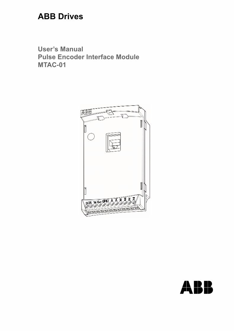
ABB Drives
User�s ManualPulse Encoder Interface ModuleMTAC-01

Pulse Encoder Interface ModuleMTAC-01
User�s Manual
3AFE68591091 REV BEN
EFFECTIVE: 04.04.2006
© 2006 ABB Oy. All Rights Reserved.


5
Safety
OverviewThis chapter states the general safety instructions that must be followed when installing and operating the MTAC-01 Pulse Encoder Interface module.
The material in this chapter must be studied before attempting any work on, or with, the unit.
In addition to the safety instructions given below, read the complete safety instructions of the specific drive you are working on.
General safety instructionsWARNING! All electrical installation and maintenance work on the drive should be carried out by qualified electricians.
The drive and adjoining equipment must be properly grounded.
Do not attempt any work on a powered drive. After switching off the input power, always allow the intermediate circuit capacitors 5 minutes to discharge before working on the drive, the motor or the motor cable. It is good practice to check (with a voltage indicating instrument) that the drive is in fact discharged before beginning work.
The motor cable terminals of the drive are at a dangerously high voltage when input power is applied, regardless of motor operation.
There can be dangerous voltages inside the drive from external control circuits even when the drive input power is shut off. Exercise appropriate care when working on the unit. Neglecting these instructions can cause physical injury or death.
Safety

6
Safety
7
Table of contents
Safety . . . . . . . . . . . . . . . . . . . . . . . . . . . . . . . . . . . . . . . . . . . . . . . . . . . . . . . 5
Overview . . . . . . . . . . . . . . . . . . . . . . . . . . . . . . . . . . . . . . . . . . . . . . . . . . . . 5General safety instructions . . . . . . . . . . . . . . . . . . . . . . . . . . . . . . . . . . . . . . . 5
Table of contents. . . . . . . . . . . . . . . . . . . . . . . . . . . . . . . . . . . . . . . . . . . . . . 7
Installation . . . . . . . . . . . . . . . . . . . . . . . . . . . . . . . . . . . . . . . . . . . . . . . . . . . 9
Preparing for installation . . . . . . . . . . . . . . . . . . . . . . . . . . . . . . . . . . . . . . . . 9Installing the module . . . . . . . . . . . . . . . . . . . . . . . . . . . . . . . . . . . . . . . . . . 10
Start-up . . . . . . . . . . . . . . . . . . . . . . . . . . . . . . . . . . . . . . . . . . . . . . . . . . . . 20
Configuration . . . . . . . . . . . . . . . . . . . . . . . . . . . . . . . . . . . . . . . . . . . . . . . . 2001 OPERATING DATA . . . . . . . . . . . . . . . . . . . . . . . . . . . . . . . . . . . . . . . . . 2050 ENCODER . . . . . . . . . . . . . . . . . . . . . . . . . . . . . . . . . . . . . . . . . . . . . . . 2119 TIMER & COUNTER . . . . . . . . . . . . . . . . . . . . . . . . . . . . . . . . . . . . . . . . 22
Diagnostics . . . . . . . . . . . . . . . . . . . . . . . . . . . . . . . . . . . . . . . . . . . . . . . . . 23
Faults/Alarms . . . . . . . . . . . . . . . . . . . . . . . . . . . . . . . . . . . . . . . . . . . . . . . . 23
Technical data . . . . . . . . . . . . . . . . . . . . . . . . . . . . . . . . . . . . . . . . . . . . . . . 24
Table of contents

8
Table of contents
9
Installation
Preparing for installation
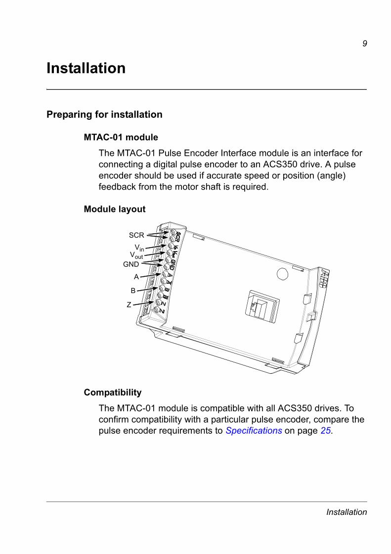
MTAC-01 moduleThe MTAC-01 Pulse Encoder Interface module is an interface for connecting a digital pulse encoder to an ACS350 drive. A pulse encoder should be used if accurate speed or position (angle) feedback from the motor shaft is required.
Module layout
CompatibilityThe MTAC-01 module is compatible with all ACS350 drives. To confirm compatibility with a particular pulse encoder, compare the pulse encoder requirements to Specifications on page 25.
SCR
A
B
Z
GND
VinVout
Installation

10
Installing the module
Delivery checkThe MTAC-01 module package contains:
� MTAC-01 module
� grounding stand-off
� panel port adapter
� this manual.
Mounting
WARNING! Follow the safety instructions given in this manual and in the ACS350 User�s Manual [3AFE68462401 (English)].
To mount the MTAC-01 module:
1. If not already off, disconnect the input power from the drive. After disconnecting the input power, wait for 5 five minutes before you start working on the drive.
2. Remove the possible control panel or panel cover from the drive.
3. Remove the grounding screw in the top left corner of the drive�s control panel slot and install the grounding stand-off in its place.
4. Ensure that the panel port adapter is attached to either the panel port of the drive or the mate part of the MTAC-01 module.
5. Gently and firmly install the MTAC-01 module to the drive�s panel slot directly from the front.
Note: Signal and power connections to the drive are automatically made through a 6-pin connector.
6. Ground the module by inserting the screw removed from the drive in the top left corner of the MTAC-01 module. Tighten the screw.
Installation
11
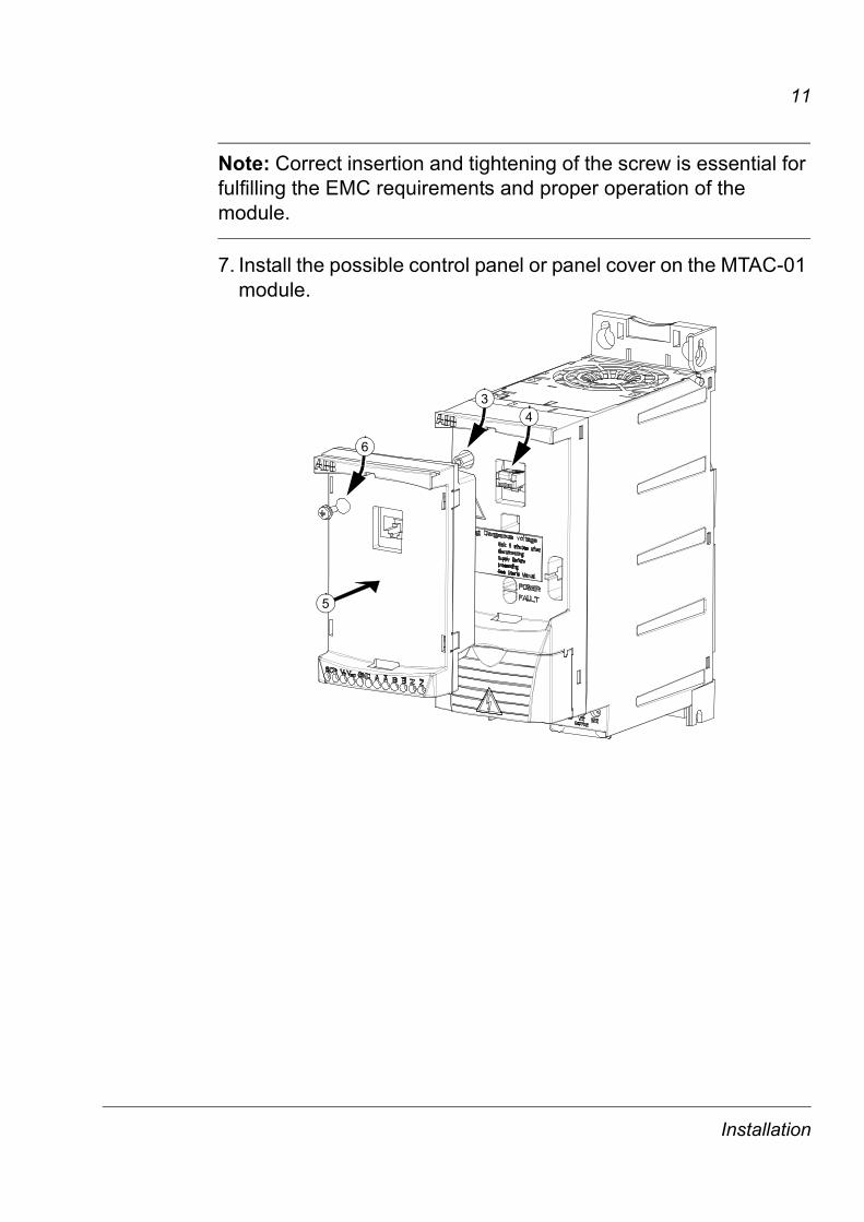
Note: Correct insertion and tightening of the screw is essential for fulfilling the EMC requirements and proper operation of the module.
7. Install the possible control panel or panel cover on the MTAC-01 module.
5
6
43
Installation

12
Wiring � GeneralThe pulse encoder should be connected to the MTAC-01 module with cables as specified below.
Terminal designations
Use the following table for reference when wiring terminals.
Cable construction 4 × (2+1) twisted pair cable with individual and overall shields
Conductor cross-sectional area 0.5 to 1.5 mm2 20 to 16 AWGMaximum cable length 100 m 330 ft
IdentificationDescription
MTAC EncoderSCR SCR/
ShieldUsed for grounding of the encoder cable shields. Connected internally to the drive ground.SCR
Vin Vcc/PWR Connected to the external power supply.Vout Vcc/PWR Connected to the encoder.GND 0 V / GND One connected to the ground of the external power
supply and the other to the ground of the encoder.GND
A 1 A A+ � Max. signal frequency: 200 kHz� Signal levels:
� Decision levels are automatically defined based on the daisy chained power supply voltage level.
� Input channels are isolated from the logic and ground.
� When the drive runs in the Forward direction,channel A should lead channel B by 90° (electrical).
� Channel Z: One pulse per revolution (used in positioning applications only).
A 1 A A-
B 2 B B+
B 2 B B-
Z 3 Z Z+
Z 3 Z Z-
Logic �1� Logic �0�24 V 12.1 V 8.3 V15 V 7.5 V 5.3 V5 V 2.5 V 1.9 V
Installation
13
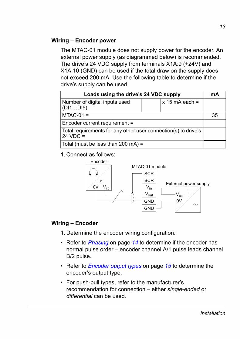
Wiring � Encoder powerThe MTAC-01 module does not supply power for the encoder. An external power supply (as diagrammed below) is recommended. The drive�s 24 VDC supply from terminals X1A:9 (+24V) and X1A:10 (GND) can be used if the total draw on the supply does not exceed 200 mA. Use the following table to determine if the drive�s supply can be used.
1. Connect as follows:
Wiring � Encoder 1. Determine the encoder wiring configuration:
� Refer to Phasing on page 14 to determine if the encoder has normal pulse order � encoder channel A/1 pulse leads channel B/2 pulse.
� Refer to Encoder output types on page 15 to determine the encoder�s output type.
� For push-pull types, refer to the manufacturer�s recommendation for connection � either single-ended or differential can be used.
Loads using the drive�s 24 VDC supply mANumber of digital inputs used (DI1�DI5)
x 15 mA each =
MTAC-01 = 35Encoder current requirement =Total requirements for any other user connection(s) to drive�s 24 VDC = Total (must be less than 200 mA) =
Vcc
Vcc0V
0V
GNDGND
SCR
Vout
Vin
SCRMTAC-01 module
External power supply
Encoder
Installation

14
2. Refer to Wiring diagrams on page 16, select the appropriate diagram, and wire the encoder.
Note: Normally, ground the cable shield only at the drive end. However, if the encoder is isolated from the motor and from the ground, connect the cable shields to both the MTAC module and the encoder housing.
Note: Do not route the encoder cables parallel to power (e.g. motor) cables.
3. Verify correct encoder phasing. See options below.
Phasing
When the encoder is connected correctly, running the drive in the Forward (positive speed reference) direction should produce a positive encoder speed feedback.
Option A: Oscilloscope test. On incremental encoders, the two output channels, usually marked A and B or 1 and 2, are 90° (electrical) apart from each other. When rotated clockwise, most encoders � but not all � have channel A/1 leading channel B/2 as illustrated below. Determine the leading channel by referring to the encoder documentation or by measuring with an oscilloscope.
The encoder output channel that leads when the drive runs Forward should be connected to MTAC terminal A. The output channel that trails should be connected to MTAC terminal B.
A or 1
A or 1
B or 2
B or 2
Z or 0
Z or 0
Diagrams show normal phasing: Pulse A/1 leads (i.e. rises earlier than) pulse B/2.
90°
Connect the zero reference output channel (usually marked 0, N or Z) only if parameter 5010 ZPLS ENABLE = 1 (ENABLE).
Installation

15
Option B: Functional test. For this test:
� Temporarily, switch the drive to scalar mode [parameter 9904 MOTOR CTRL MODE = 3 (SCALAR:FREQ)], if not already there.
� Run the drive in the forward direction.
� Verify that parameter 0147 MECH REVS is increasing in the positive direction.
� If not, switch the A/A (or 1/1) connections.
Encoder output types
The following diagrams identify the typical encoder output types.
Push-pull Open collector (sinking)
Open emitter (sourcing)
VCC = Encoder input power supply voltageRL = Load resistor at encoder output channel
OUT
VCC
OUT
VCC
RL
OUT
VCC
RL
Installation
16
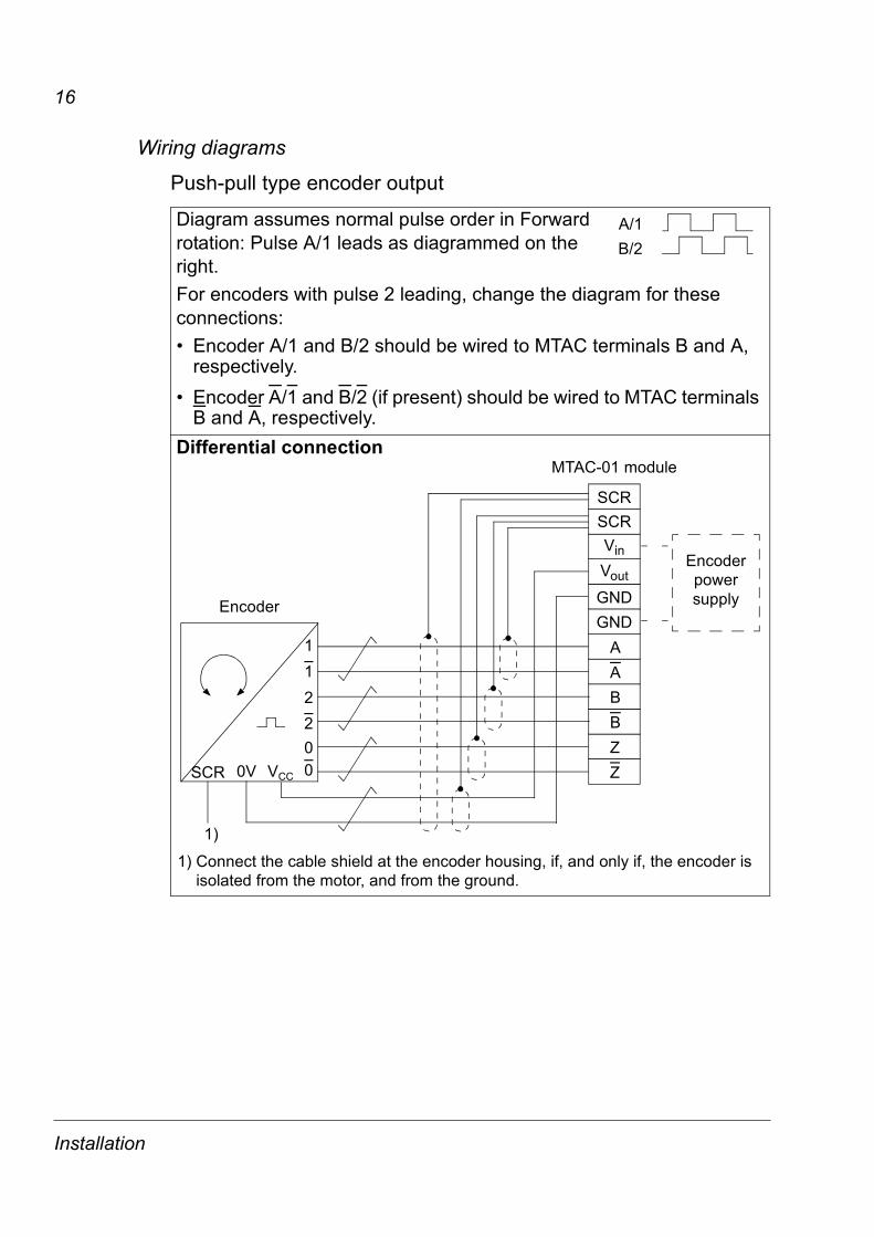
Wiring diagrams
Push-pull type encoder output
Diagram assumes normal pulse order in Forward rotation: Pulse A/1 leads as diagrammed on the right.For encoders with pulse 2 leading, change the diagram for these connections:� Encoder A/1 and B/2 should be wired to MTAC terminals B and A,
respectively.� Encoder A/1 and B/2 (if present) should be wired to MTAC terminals
B and A, respectively.Differential connection
A/1B/2
11
00V VCC
22
0SCR
1)
AABBZZ
MTAC-01 module
1) Connect the cable shield at the encoder housing, if, and only if, the encoder is isolated from the motor, and from the ground.
Encoder power supply
SCR
Vin
GND
Vout
GND
SCR
Encoder
Installation
17
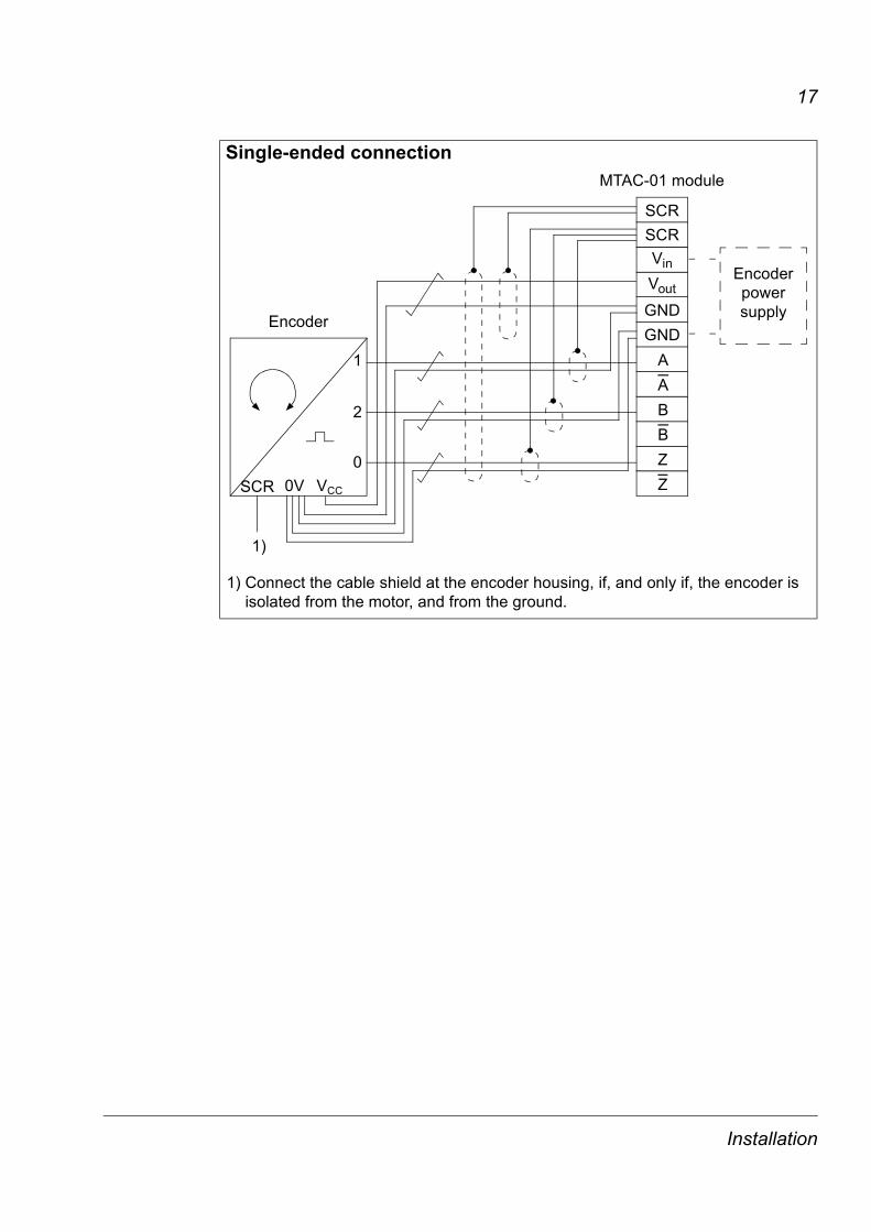
Single-ended connection
1) Connect the cable shield at the encoder housing, if, and only if, the encoder is isolated from the motor, and from the ground.
1
00V VCC
2
SCR
1)
AABBZZ
MTAC-01 module
Encoder power supply
SCR
Vin
GND
Vout
GND
SCR
Encoder
Installation
18
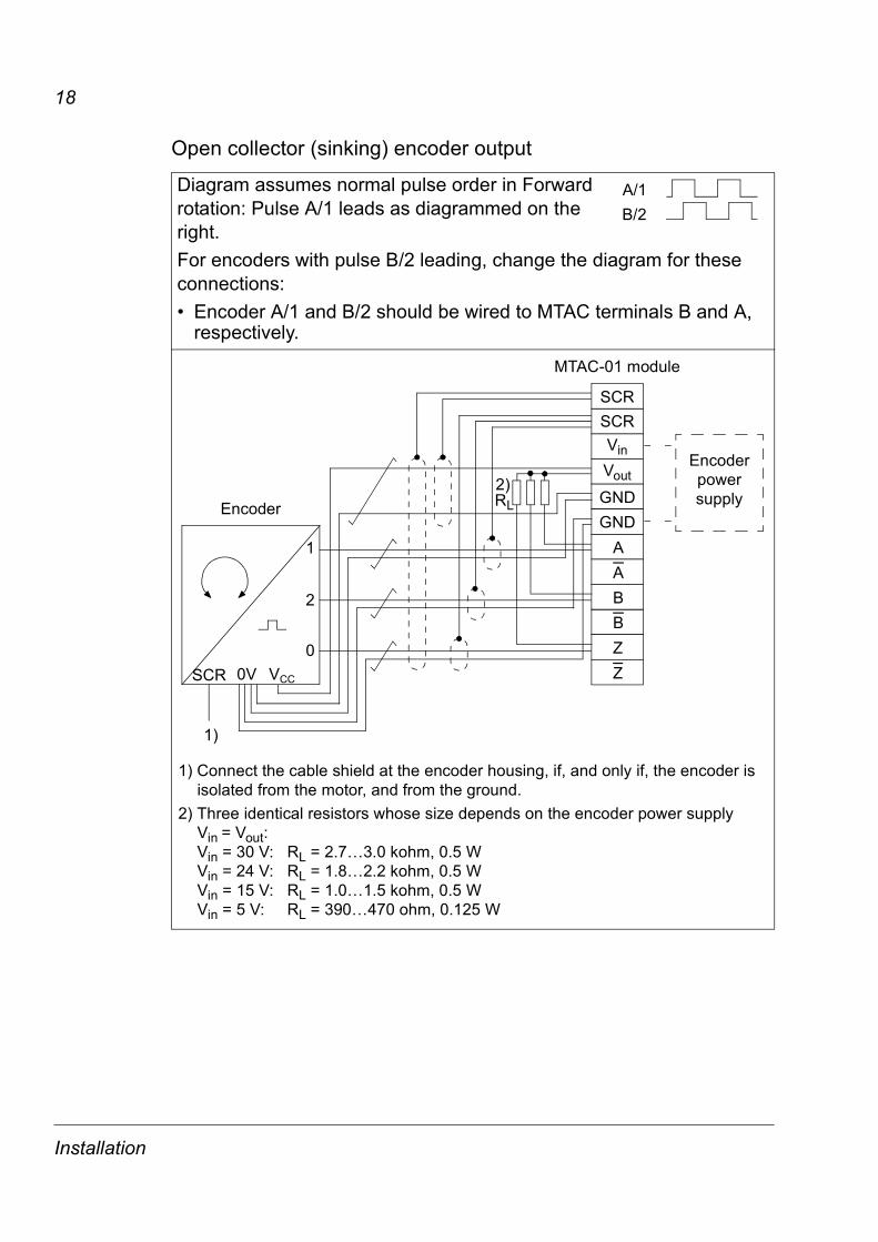
Open collector (sinking) encoder output
Diagram assumes normal pulse order in Forward rotation: Pulse A/1 leads as diagrammed on the right.For encoders with pulse B/2 leading, change the diagram for these connections:� Encoder A/1 and B/2 should be wired to MTAC terminals B and A,
respectively.
A/1B/2
1
00V VCC
2
SCR
1)
AABBZZ
MTAC-01 module
1) Connect the cable shield at the encoder housing, if, and only if, the encoder is isolated from the motor, and from the ground.
2) Three identical resistors whose size depends on the encoder power supply Vin = Vout:Vin = 30 V: RL = 2.7�3.0 kohm, 0.5 WVin = 24 V: RL = 1.8�2.2 kohm, 0.5 WVin = 15 V: RL = 1.0�1.5 kohm, 0.5 WVin = 5 V: RL = 390�470 ohm, 0.125 W
Encoder power supply
SCR
Vin
GND
Vout
GND
SCR
Encoder RL2)
Installation
19
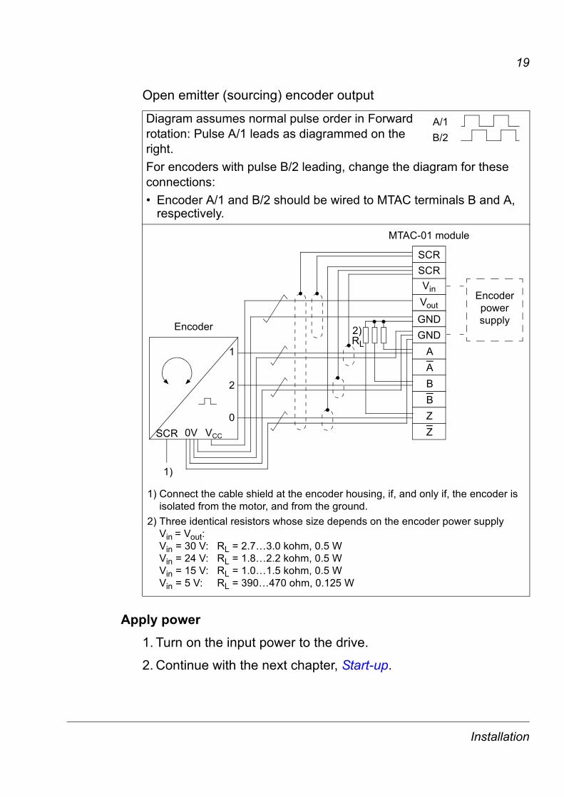
Open emitter (sourcing) encoder output
Apply power
1. Turn on the input power to the drive.
2. Continue with the next chapter, Start-up.
Diagram assumes normal pulse order in Forward rotation: Pulse A/1 leads as diagrammed on the right.For encoders with pulse B/2 leading, change the diagram for these connections:� Encoder A/1 and B/2 should be wired to MTAC terminals B and A,
respectively.
A/1B/2
1) Connect the cable shield at the encoder housing, if, and only if, the encoder is isolated from the motor, and from the ground.
2) Three identical resistors whose size depends on the encoder power supply Vin = Vout:Vin = 30 V: RL = 2.7�3.0 kohm, 0.5 WVin = 24 V: RL = 1.8�2.2 kohm, 0.5 WVin = 15 V: RL = 1.0�1.5 kohm, 0.5 WVin = 5 V: RL = 390�470 ohm, 0.125 W
1
00V VCC
2
SCR
1)
AABBZZ
MTAC-01 module
Encoder power supply
SCR
Vin
GND
Vout
GND
SCR
EncoderRL2)
Installation
20
Start-up
ConfigurationTo configure the operation of the MTAC-01 module:
1. Power up the drive.
2. Use the control panel on the drive or the DriveWindow LightPC tool and set group 50 ENCODER parameters described on page 21.
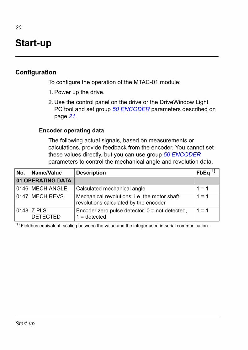
Encoder operating dataThe following actual signals, based on measurements or calculations, provide feedback from the encoder. You cannot set these values directly, but you can use group 50 ENCODER parameters to control the mechanical angle and revolution data.
No. Name/Value Description FbEq 1)
01 OPERATING DATA0146 MECH ANGLE Calculated mechanical angle 1 = 10147 MECH REVS Mechanical revolutions, i.e. the motor shaft
revolutions calculated by the encoder1 = 1
0148 Z PLS DETECTED
Encoder zero pulse detector. 0 = not detected, 1 = detected
1 = 1
1) Fieldbus equivalent, scaling between the value and the integer used in serial communication.
Start-up
21
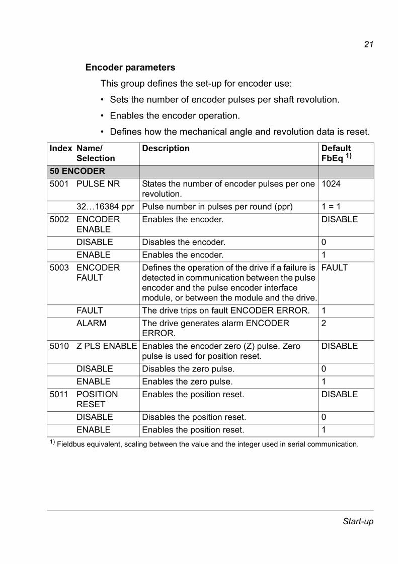
Encoder parametersThis group defines the set-up for encoder use:
� Sets the number of encoder pulses per shaft revolution.
� Enables the encoder operation.
� Defines how the mechanical angle and revolution data is reset.
Index Name/Selection
Description DefaultFbEq 1)
50 ENCODER5001 PULSE NR States the number of encoder pulses per one
revolution.1024
32�16384 ppr Pulse number in pulses per round (ppr) 1 = 15002 ENCODER
ENABLEEnables the encoder. DISABLE
DISABLE Disables the encoder. 0ENABLE Enables the encoder. 1
5003 ENCODER FAULT
Defines the operation of the drive if a failure is detected in communication between the pulse encoder and the pulse encoder interface module, or between the module and the drive.
FAULT
FAULT The drive trips on fault ENCODER ERROR. 1ALARM The drive generates alarm ENCODER
ERROR.2
5010 Z PLS ENABLE Enables the encoder zero (Z) pulse. Zero pulse is used for position reset.
DISABLE
DISABLE Disables the zero pulse. 0ENABLE Enables the zero pulse. 1
5011 POSITION RESET
Enables the position reset. DISABLE
DISABLE Disables the position reset. 0ENABLE Enables the position reset. 1
1) Fieldbus equivalent, scaling between the value and the integer used in serial communication.
Start-up
22
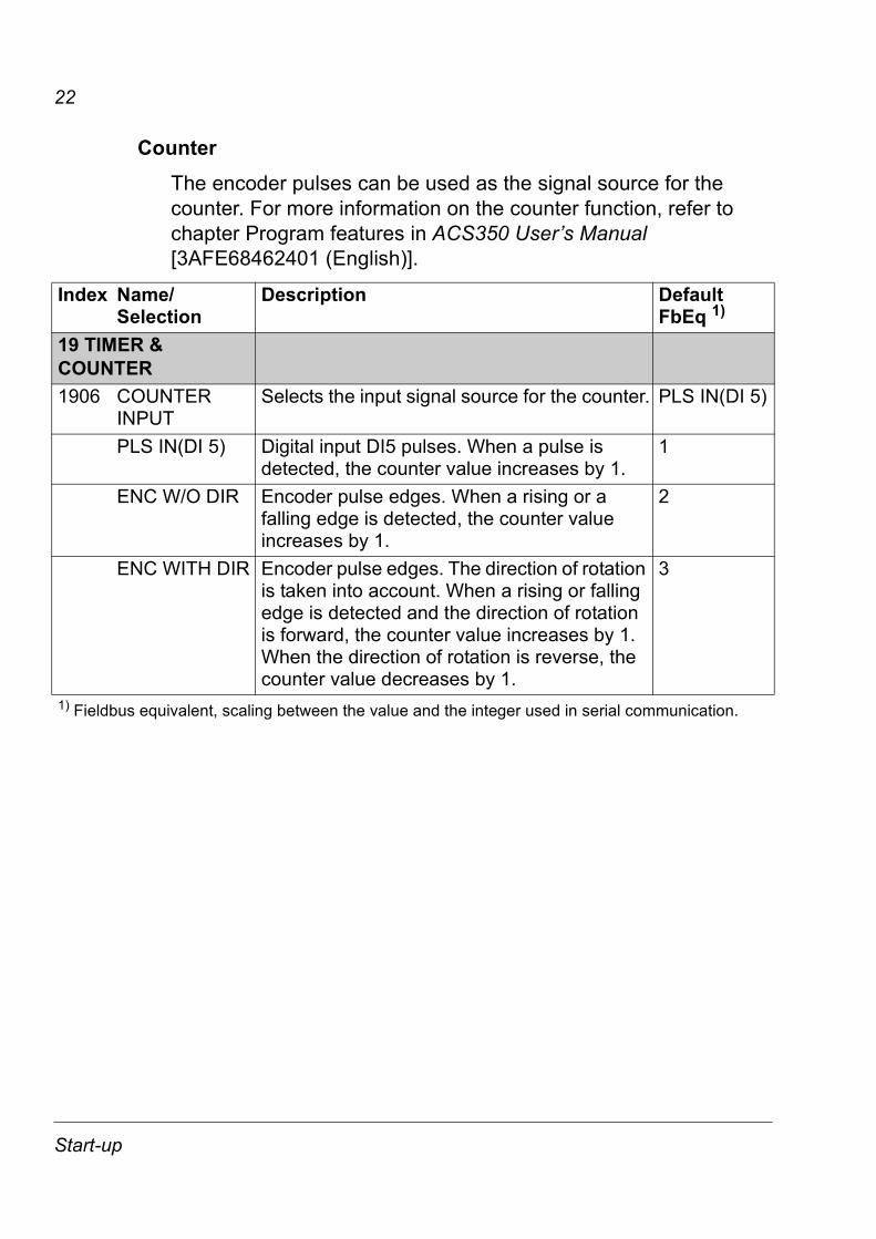
CounterThe encoder pulses can be used as the signal source for the counter. For more information on the counter function, refer to chapter Program features in ACS350 User�s Manual [3AFE68462401 (English)].
Index Name/Selection
Description DefaultFbEq 1)
19 TIMER & COUNTER1906 COUNTER
INPUTSelects the input signal source for the counter. PLS IN(DI 5)
PLS IN(DI 5) Digital input DI5 pulses. When a pulse is detected, the counter value increases by 1.
1
ENC W/O DIR Encoder pulse edges. When a rising or a falling edge is detected, the counter value increases by 1.
2
ENC WITH DIR Encoder pulse edges. The direction of rotation is taken into account. When a rising or falling edge is detected and the direction of rotation is forward, the counter value increases by 1. When the direction of rotation is reverse, the counter value decreases by 1.
3
1) Fieldbus equivalent, scaling between the value and the integer used in serial communication.
Start-up

23
Diagnostics
Diagnostics
Faults/AlarmsIf the ACS350 detects that the encoder signal is lost, the drive operation and the diagnostic message are both controlled by parameter 5003 ENCODER FAULT:
� 5003 = 1 (FAULT) � The drive generates a fault (23 ENCODER ERR), and the motor coasts to a stop.
� 5003 = 2 (ALARM) � The drive generates an alarm (2024 ENCODER ERROR) and operates as if parameter 5002 ENCODER ENABLE = 0 (DISABLE), that is, speed feedback is derived from the internal motor model.
In case of a fault or alarm signal, check for and correct the following:
Note: The validity of the encoder signal is also checked during the ID run. See parameter 9910 MOTOR ID RUN. If the drive detects an encoder problem during the ID run, the drive generates an alarm. Parameter 5003 ENCODER FAULT controls the drive�s fault/alarm response to encoder errors only after the ID run is completed.
CODE FAULT/ALARM 1) CAUSE WHAT TO DO0023 ENCODER ERR
(7301)0306 bit 6
Communication fault between pulse encoder and pulse encoder interface module or between module and drive.
Check pulse encoder and its wiring, pulse encoder interface module and its wiring and parameter group 50 ENCODER settings.2024 ENCODER ERROR
(7310)0309 bit 7
1) Name, code for fieldbus communication (in parentheses) and bit in fault/alarm word.
24
Technical data
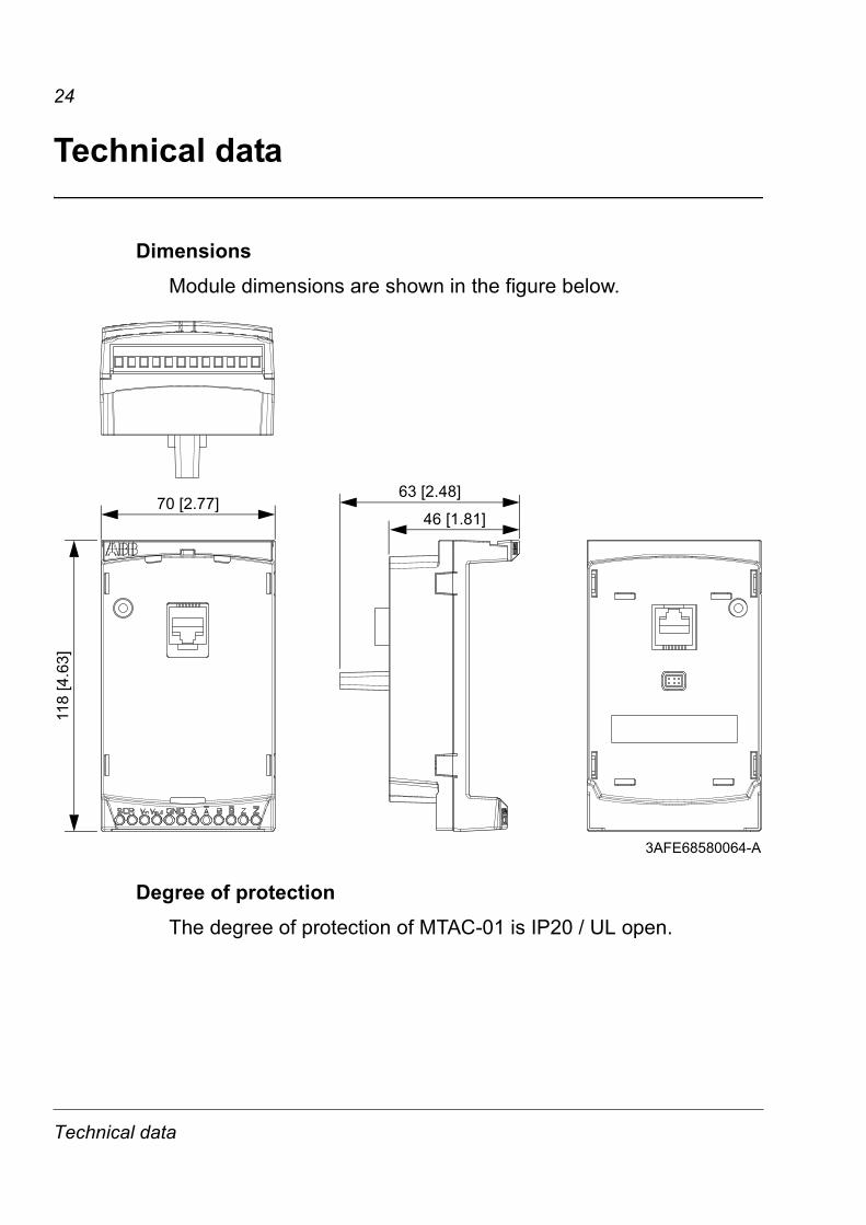
DimensionsModule dimensions are shown in the figure below.
Degree of protectionThe degree of protection of MTAC-01 is IP20 / UL open.
63 [2.48]
46 [1.81]70 [2.77]
118
[4.6
3]
3AFE68580064-A
Technical data
25
Ambient conditionsTemperature -10�+40°C (14�+104°F). No frost allowed.
ConnectorsConnectors on the module:
� one 12-pin screw-type, non-detachable terminal block that accepts wire connectors up to 1.5 mm2 (16 AWG) for encoder interface
� two RJ-45 connectors for panel pass-through
� 6-pin connector for drive interface
� grounding screw/stand-off for connection of the SCR terminals of the drive and the MTAC-01 module.
SpecificationsModule specifications
The MTAC-01 module:
� supports three channels: CH A, CH B, CH Z
� includes pass-through terminals to connect an external power supply (required) to the pulse encoder
� has all of its materials UL-approved.
Channel specifications
Channel specifications:
� differential or single-ended
� maximum input frequency: 200 kHz
� input voltage range (measured at the MTAC module): see Terminal designations on page 12
� nominal input impedance (at 24 VDC): 20 kohm
� isolated from the logic and ground.
Technical data

26
Technical data


3AFE
6859
1091
RE
V B
/ E
NE
FFEC
TIV
E: 0
4.04
.200
6
ABB OyAC DrivesP.O. Box 184FI-00381 HELSINKIFINLANDTelephone +358 10 22 11Fax +358 10 22 22681Internet http://www.abb.com
ABB Inc.Automation TechnologiesDrives & Motors16250 West Glendale DriveNew Berlin, WI 53151USATelephone 262 785-3200
800-HELP-365Fax 262 780-5135
ABB LimitedDaresbury ParkDaresburyWarringtonCheshireWA4 4BTUNITED KINGDOMTelephone +44 1925 741111Fax +44 1925 74121
ABB Beijing Drive Systems Co. Ltd.No. 1, Block D, A-10 Jiuxianqiao BeiluChaoyang DistrictBeijing, P.R. China, 100015Telephone +86 10 5821 7788Fax +86 10 5821 7618Internet http://www.abb.com