Embed Size (px)
Citation preview
DarmstadtUniversity ofTechnology
OFDM Basics for Wireless
Communications
Institute ofMicroelectronicSystems
2VLSI_Comms WS03-04/Generalities L.D. Kabulepa
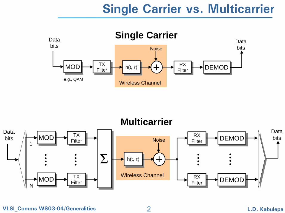
Single Carrier vs. Multicarrier
Single Carrier
MODMOD
e.g., QAM
TXFilterTX
Filter h(t, τ)h(t, τ) + RXFilterRX
Filter DEMODDEMOD
Noise
Wireless Channel
Databits
Databits
MulticarrierMODMOD TX
FilterTX
FilterRX
FilterRX
Filter DEMODDEMODDatabits
Databits
MODMOD TXFilterTX
FilterRX
FilterRX
Filter DEMODDEMOD
Σ h(t, τ)h(t, τ) +
Noise
Wireless Channel
1
N
3VLSI_Comms WS03-04/Generalities L.D. Kabulepa
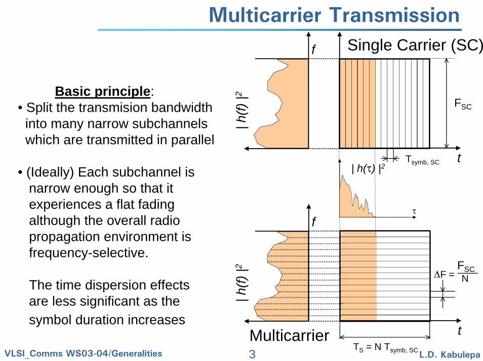
Multicarrier Transmission
FSC
tTsymb, SC
f
| h(f)
|2
τ
| h(τ) |2
Single Carrier (SC)
Multicarrier
FSC
t
f| h
(f) |2
F = N
TS = N Tsymb, SC
Basic principle:• Split the transmision bandwidth into many narrow subchannelswhich are transmitted in parallel
• (Ideally) Each subchannel is narrow enough so that it experiences a flat fadingalthough the overall radiopropagation environment is frequency-selective.
The time dispersion effects are less significant as thesymbol duration increases
4VLSI_Comms WS03-04/Generalities L.D. Kabulepa
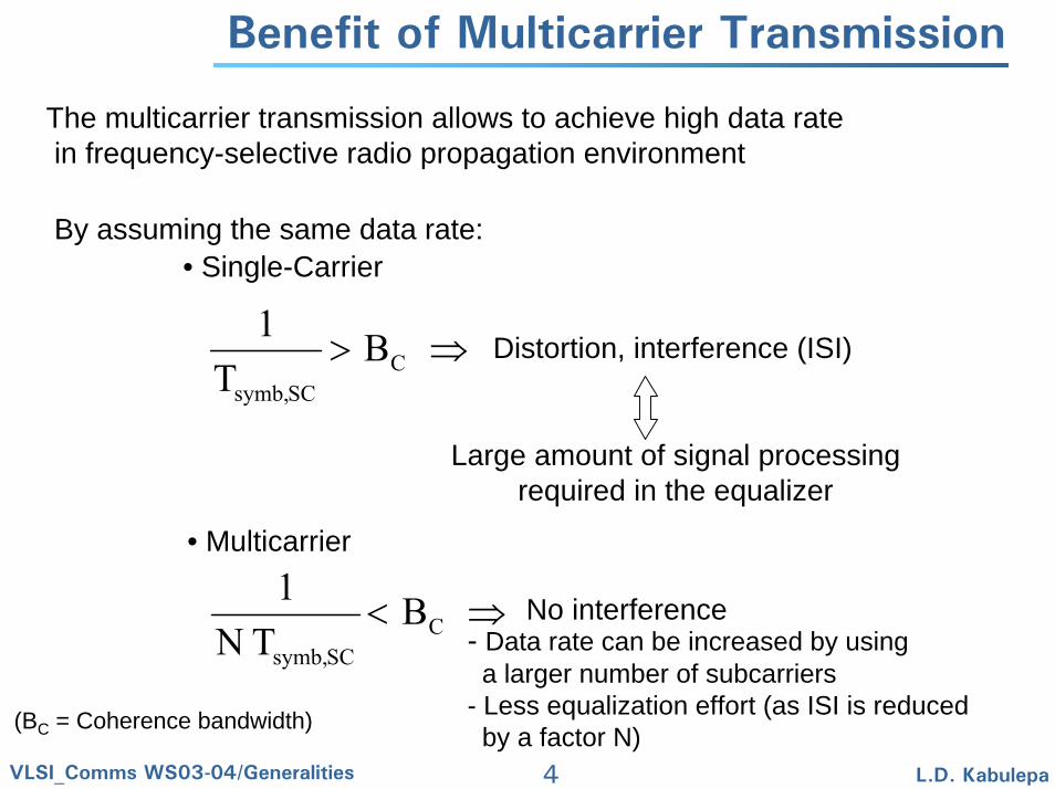
Benefit of Multicarrier Transmission
The multicarrier transmission allows to achieve high data ratein frequency-selective radio propagation environment
By assuming the same data rate:• Single-Carrier
⇒> CSCsymb,
BT
1Distortion, interference (ISI)
Large amount of signal processingrequired in the equalizer
• Multicarrier
⇒< CSCsymb,
BT N
1No interference
- Data rate can be increased by usinga larger number of subcarriers
- Less equalization effort (as ISI is reducedby a factor N)(BC = Coherence bandwidth)
5VLSI_Comms WS03-04/Generalities L.D. Kabulepa
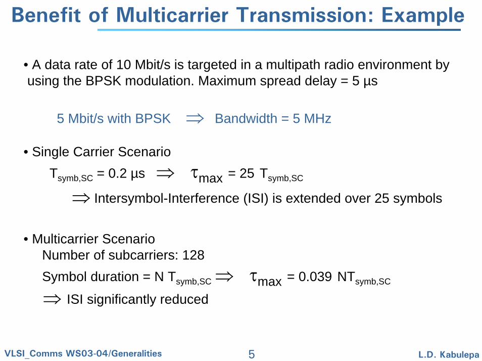
Benefit of Multicarrier Transmission: Example
• A data rate of 10 Mbit/s is targeted in a multipath radio environment byusing the BPSK modulation. Maximum spread delay = 5 µs
5 Mbit/s with BPSK ⇒ Bandwidth = 5 MHz
• Single Carrier Scenario Tsymb,SC = 0.2 µs ⇒ τmax = 25 Tsymb,SC
• Multicarrier ScenarioNumber of subcarriers: 128Symbol duration = N Tsymb,SC ⇒ τmax = 0.039 NTsymb,SC
⇒ ISI significantly reduced
⇒ Intersymbol-Interference (ISI) is extended over 25 symbols
6VLSI_Comms WS03-04/Generalities L.D. Kabulepa
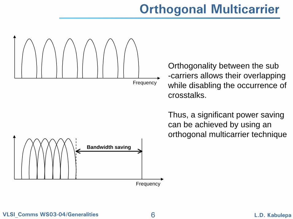
Orthogonal Multicarrier
Frequency
Orthogonality between the sub-carriers allows their overlappingwhile disabling the occurrence ofcrosstalks.
Thus, a significant power savingcan be achieved by using anorthogonal multicarrier technique
Frequency
Bandwidth saving
7VLSI_Comms WS03-04/Generalities L.D. Kabulepa
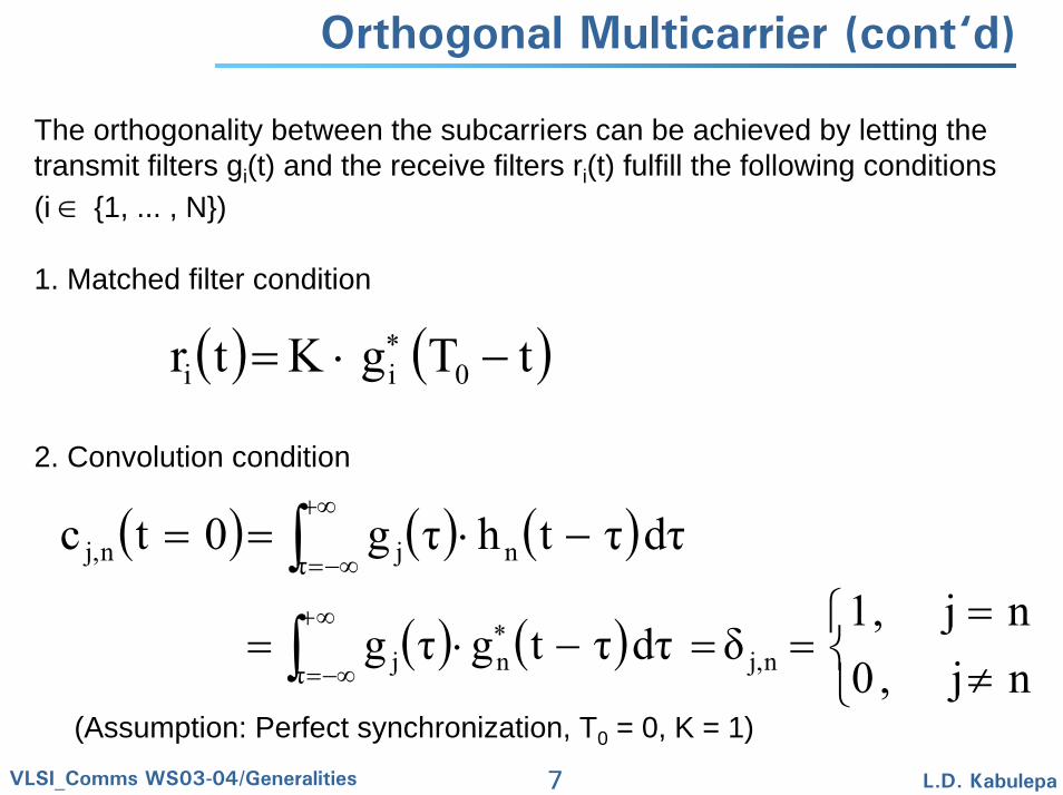
Orthogonal Multicarrier (cont‘d)
The orthogonality between the subcarriers can be achieved by letting thetransmit filters gi(t) and the receive filters ri(t) fulfill the following conditions(i ∈ {1, ... , N})
1. Matched filter condition
2. Convolution condition
( ) ( )tTgKtr 0ii −⋅= ∗
( ) ( ) ( )dττthτg0tc nτ jnj, −⋅== ∫+∞
−∞=
( ) ( )⎩⎨⎧
≠=
==−⋅= ∗∞+
−∞=∫ nj,0nj,1
δ dττtgτg nj,nτ j
(Assumption: Perfect synchronization, T0 = 0, K = 1)
8VLSI_Comms WS03-04/Generalities L.D. Kabulepa
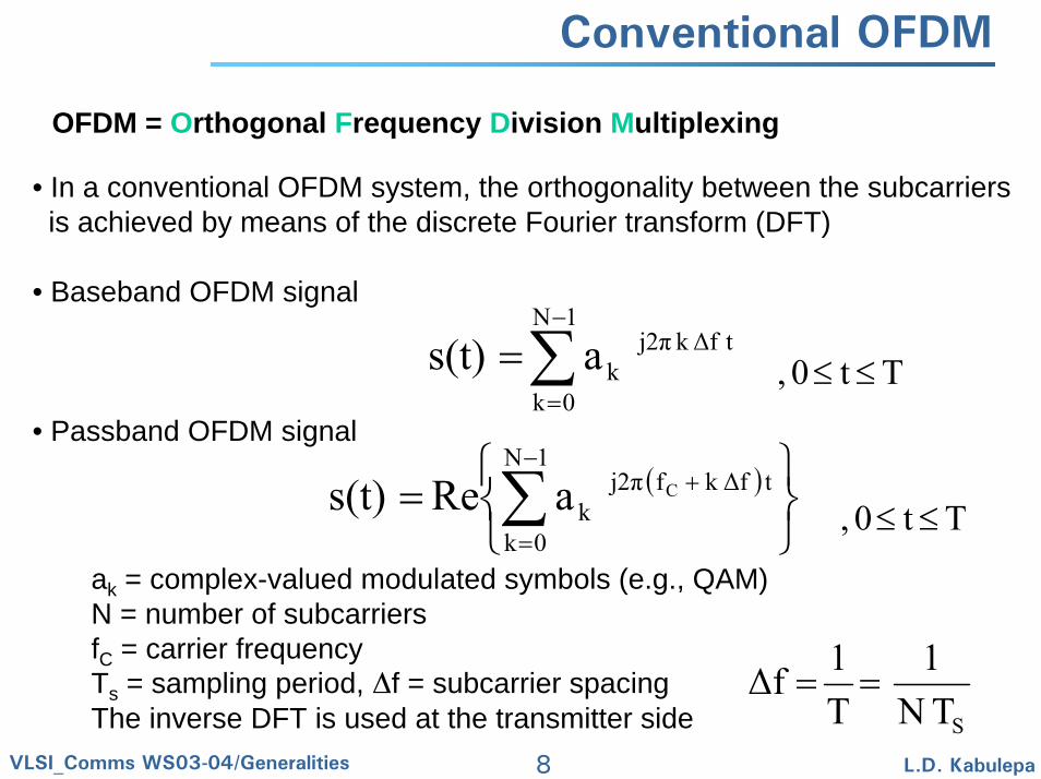
Conventional OFDM
OFDM = Orthogonal Frequency Division Multiplexing
• In a conventional OFDM system, the orthogonality between the subcarriersis achieved by means of the discrete Fourier transform (DFT)
• Baseband OFDM signal
• Passband OFDM signal
∑−
=
=1N
0k
t∆fkj2πkas(t)
( )
⎭⎬⎫
⎩⎨⎧
= ∑−
=
+1N
0k
t∆fk fj2πk
CaRes(t)
ak = complex-valued modulated symbols (e.g., QAM)N = number of subcarriersfC = carrier frequencyTs = sampling period, f = subcarrier spacingThe inverse DFT is used at the transmitter side
Tt0, ≤≤
Tt0, ≤≤
STN1
T1∆f ==
9VLSI_Comms WS03-04/Generalities L.D. Kabulepa
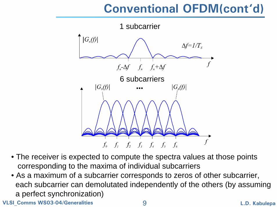
Conventional OFDM(cont‘d)1 subcarrier
• The receiver is expected to compute the spectra values at those pointscorresponding to the maxima of individual subcarriers
• As a maximum of a subcarrier corresponds to zeros of other subcarrier,each subcarrier can demolutated independently of the others (by assuminga perfect synchronization)
6 subcarriers
10VLSI_Comms WS03-04/Generalities L.D. Kabulepa
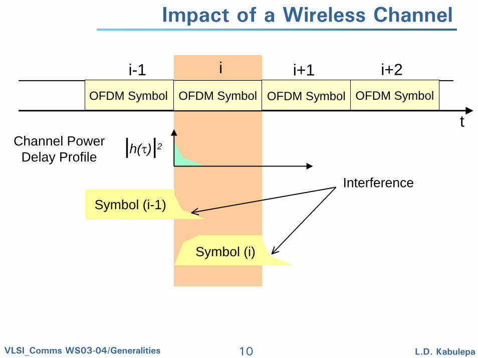
Impact of a Wireless Channel
OFDM Symbol OFDM Symbol OFDM Symbol OFDM Symbol
t
ii-1 i+1 i+2
|h(τ)|2
Symbol (i-1)
Symbol (i)
Interference
Channel PowerDelay Profile
11VLSI_Comms WS03-04/Generalities L.D. Kabulepa
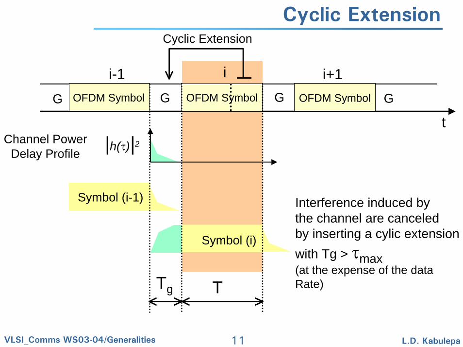
Cyclic Extension
OFDM Symbol OFDM Symbol OFDM Symbol
t
ii-1 i+1
|h(τ)|2
Symbol (i-1)
Symbol (i)
Channel PowerDelay Profile
Cyclic Extension
Tg T
Interference induced bythe channel are canceledby inserting a cylic extensionwith Tg > τmax(at the expense of the dataRate)
GGG G
12VLSI_Comms WS03-04/Generalities L.D. Kabulepa
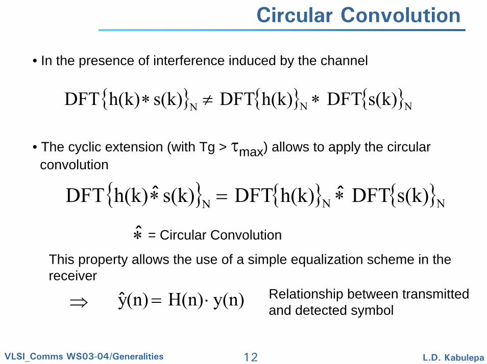
Circular Convolution
• In the presence of interference induced by the channel
• The cyclic extension (with Tg > τmax) allows to apply the circular convolution
{ } { } { }NNN s(k)DFTh(k)DFTs(k)h(k)DFT ∗≠∗
{ } { } { }NNN s(k)DFTh(k)DFTs(k)h(k)DFT ∗=∗ ˆˆ
∗̂ = Circular Convolution
This property allows the use of a simple equalization scheme in thereceiver
Relationship between transmittedand detected symbol
y(n)H(n)(n)y ⋅=ˆ⇒
13VLSI_Comms WS03-04/Generalities L.D. Kabulepa
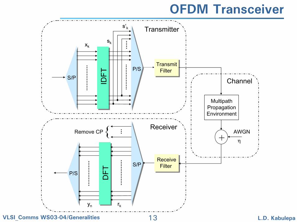
OFDM Transceiver
P/SS/P
DFT
S/PP/S
IDFT
ReceiveFilter
ReceiveFilter
TransmitFilter
TransmitFilter
MultipathPropagationEnvironment
+AWGNη
Transmitter
Receiver
Channel
xksk
rkyn
s‘k
Remove CP{
14VLSI_Comms WS03-04/Generalities L.D. Kabulepa
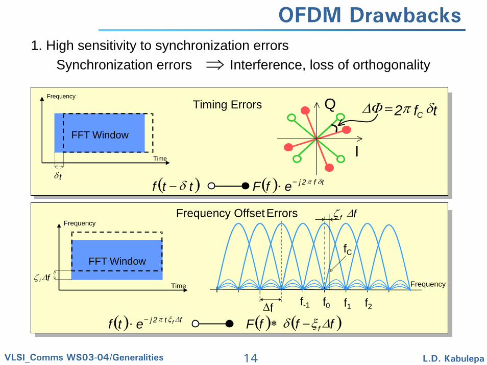
OFDM Drawbacks1. High sensitivity to synchronization errors
Synchronization errors ⇒ Interference, loss of orthogonality
( ) ( ) tf2jefFttf δπδ −⋅−
Timing Errors tf2 C δπ∆Φ =
I
Q
FFT Window
Frequency
Time
tδ
FFT Window
Frequency
Timeff∆ζ
( ) ( ) ( )fffFetf fft2j f ∆ξδ∆ξπ −∗⋅ −
Frequency Offset Errors
∆f f-1 f1 f2f0
ff ∆ζ
fC
Frequency
15VLSI_Comms WS03-04/Generalities L.D. Kabulepa
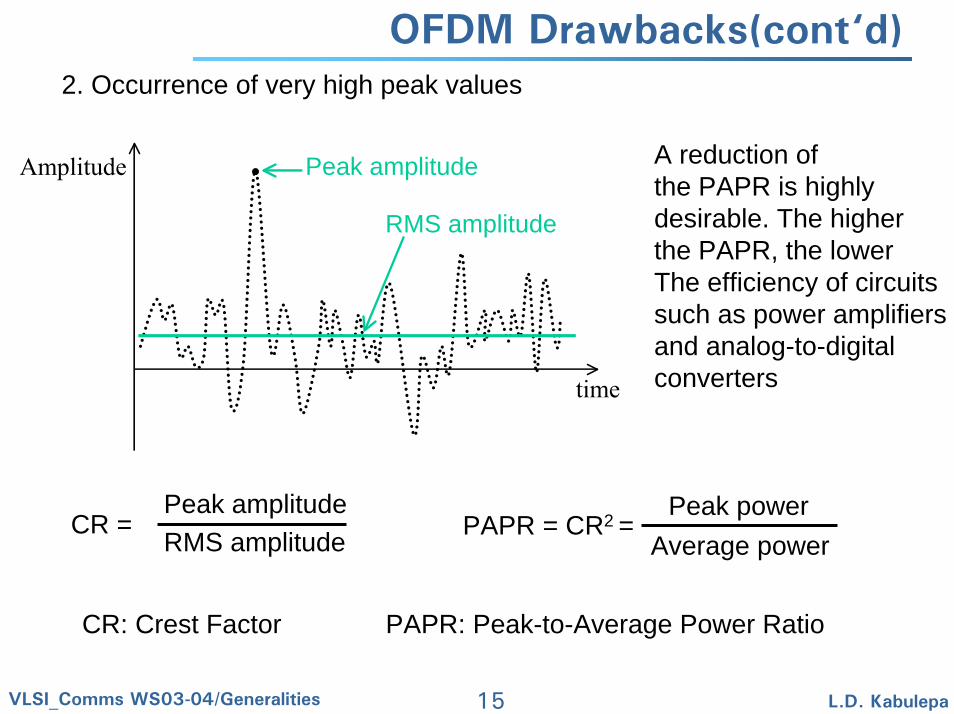
OFDM Drawbacks(cont‘d)2. Occurrence of very high peak values
A reduction ofthe PAPR is highlydesirable. The higherthe PAPR, the lowerThe efficiency of circuitssuch as power amplifiersand analog-to-digital converters
Peak amplitude
RMS amplitude
time
Amplitude
Peak amplitudeRMS amplitude PAPR = CR2 =
Peak powerAverage power
CR =
CR: Crest Factor PAPR: Peak-to-Average Power Ratio
16VLSI_Comms WS03-04/Generalities L.D. Kabulepa
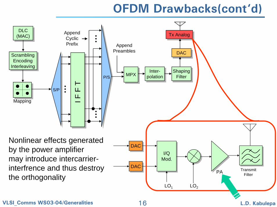
OFDM Drawbacks(cont‘d)
MPX
Tx Analog
DAC
ShapingFilter
Inter-polation
DLC(MAC)DLC
(MAC)
ScramblingEncoding
Interleaving
Mapping I F F
T
AppendCyclicPrefix
S/P
P/SInter-
polationShaping
Filter
DAC
Tx Analog
MPX
AppendPreambles
I/QMod.
DAC
DACDAC
DAC
I/QMod.
LO1 LO2
PA TransmitFilter
Nonlinear effects generatedby the power amplifiermay introduce intercarrier-interfrence and thus destroythe orthogonality