Embed Size (px)
Citation preview

Flux ropes in space plasmas
Alexey Isavnin Supervisors: Emilia Kilpua, Hannu Koskinen
University of Helsinki, Finland
Graduate seminar series 2014, March 24


Outline
• Space weather: Sun–Earth connection, its mechanism and effect on us
• Coronal mass ejections: multipart configuration and embedded flux ropes
• Evolution of solar flux ropes: deflections and rotations
• Magnetospheric flux ropes: evolution and substorm dynamics
1/31
Space weather
2/31
Space weather describes the conditions in space that affect Earth and its technological systems

Space weather. Spectacular…
3/31

Space weather. Spectacular…
4/31

Space weather. Spectacular but hazardous
5/31
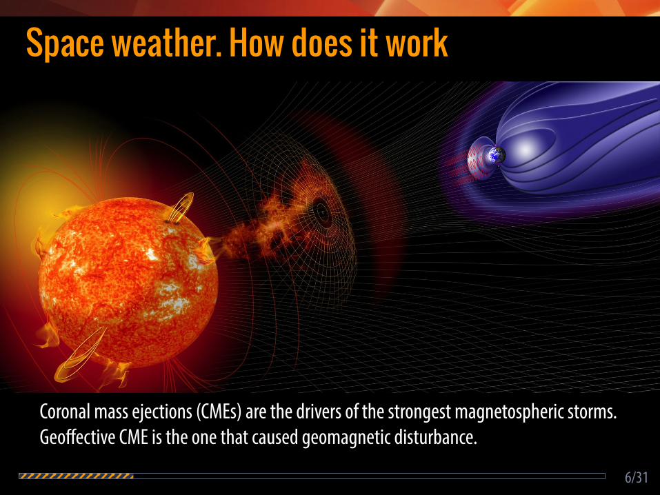
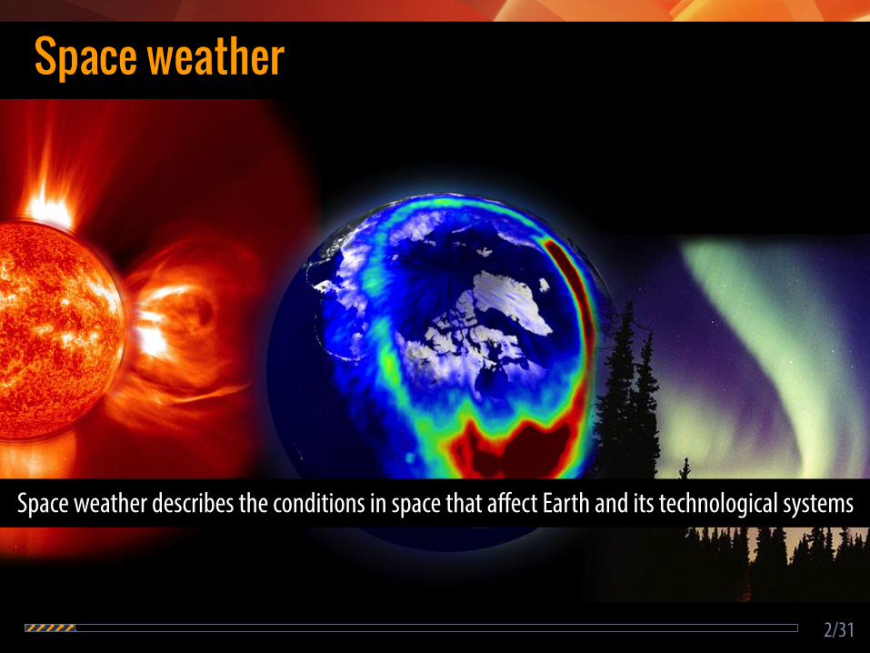
Space weather. How does it work
6/31
Coronal mass ejections (CMEs) are the drivers of the strongest magnetospheric storms. Geoffective CME is the one that caused geomagnetic disturbance.

Space weather. How does it work
7/31

Flux rope CMEs and their internal structure

Magnetic flux ropes
8/31
• Local cylindrical geometry • Helical magnetic field lines with zero twist in the core and
increasing with the distance from the axis • Maximum magnetic field strength along the axis

Coronal mass ejection
9/31
CMEs are not just explosions on the Sun but eruptions of magnetic flux ropes.

Flux rope formation
10/31
Flux rope forms prior to CME. Flux rope eruption happens in conjunction with solar flare.
CME observations
11/31
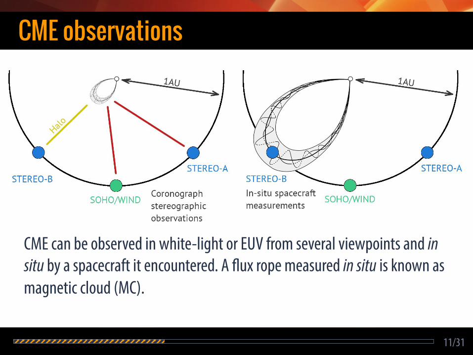
CME can be observed in white-light or EUV from several viewpoints and in situ by a spacecraft it encountered. A flux rope measured in situ is known as magnetic cloud (MC).

Five-part CME structure
12/31
The dark cavity represents the flux rope. Bright core is the prominence material. Faint loop is the signature of a shock wave driven by the CME.
Five-part ICME structure
13/31
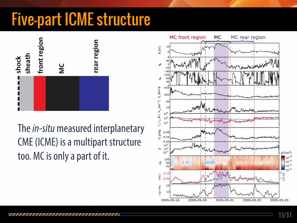
The in-situ measured interplanetary CME (ICME) is a multipart structure too. MC is only a part of it.

Five-part ICME structure
14/31
Front, rear and MC regions consist from physically different plasma, i.e. originate from different physical processes or regions near the Sun.

Conclusions
15/31
• CMEs and ICMEs are both multipart structures with five distinct parts distinguishable.
• Flux rope occupies the dark cavity area of a CME observable in white light.
• Front and rear MC parts originate near the Sun and correspond to piled-up material (bright loop) in front of the flux rope and prominence material (bright core), respectively.
• Sheath region region form during fast CME propagation and occupies the region of diffusive emission.

Evolution of solar flux ropes

Flux rope evolution
• Expansion • Longitudinal deflection • Latitudinal deflection • Rotation • Distortion
Motivation: Change of flux rope orientation can result in change of geomagnetic effectiveness. Important for space weather forecasting.
16/31

Tracking a flux rope requires several tools
17/31
0 Rs 5 Rs 20 Rs 1 AU
solar disk observations coronagraph imaging in-situ measurements

18/31
Eruptive prominence
0 Rs 5 Rs 20 Rs 1 AU
Post-eruption arcades or eruptive prominences give idea about geometrical orientation of the flux rope in the lower corona.
Flux rope signatures in the lower corona

19/31
0 Rs 5 Rs 20 Rs 1 AU
Coronagraph observations of flux ropes
Forward modeling of ejected flux ropes gives an estimate of their orientation in the inner heliosphere.
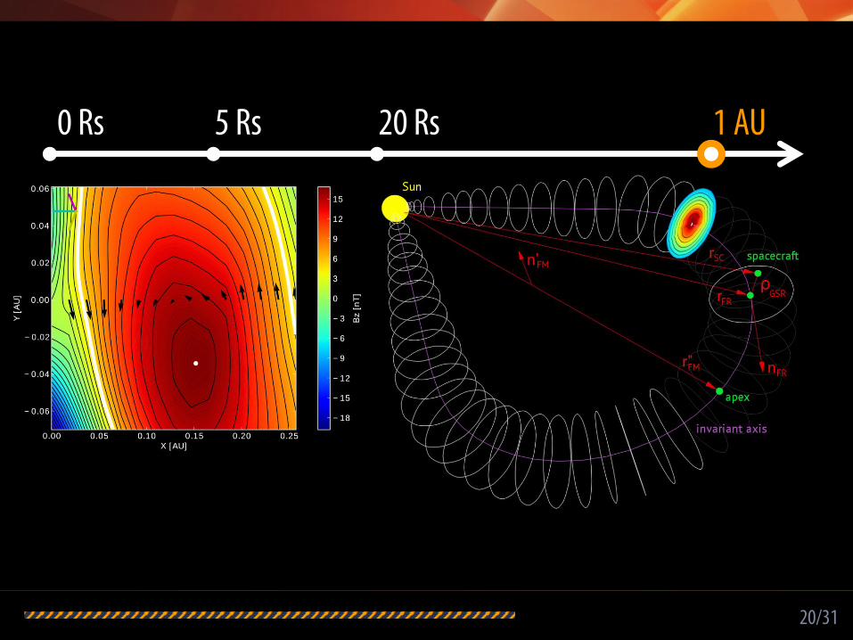
20/31
0 Rs 5 Rs 20 Rs 1 AU
In-situ measurements as a constraint
Local orientation of the flux rope invariant axis is only a constraint for its global orientation.
Magnetic field map by Grad-Shafranov reconstruction

21/31
0 Rs 5 Rs 20 Rs 1 AU
Flux rope propagation through MHD solar wind
We propagate the flux rope in 3D through MHD-simulated solar wind using in-situ measurements as a constraint.

Longitudinal deflection
22/31
Latitudinal deflection is caused by the magnetic interaction with the Parker-spiral-structured solar wind.

Deflection towards equatorial plane
23/31
Flux rope global axis direction during its travel from the Sun to 1 AU.
0 Rs 5 Rs 20 Rs 1 AU

Rotation relative to heliospheric current sheet
24/31
Flux rope orientation superimposed on velocity (top) and magnetic energy density (bottom) maps at 1 AU for two events.

Conclusions
25/31
• Flux ropes continuously deflect towards the solar equatorial plane during their travel from the Sun to 1 AU.
• Flux ropes rotate while getting approximately aligned with heliospheric current sheet.
• Geometrical evolution of ejected flux ropes in the inner heliosphere was found to be caused by magnetic interaction with Parker-spiral-structured solar wind.
• 60% of flux evolution happens during the first 14% of their travel distance from the Sun to 1 AU.

Evolution of magnetospheric flux ropes

Magnetospheric substorm dynamics
26/31
1. Energy from the solar wind due to interaction with magnetic structures within is stored as excess magnetic flux in the magnetosphere.
2. A reconnection site (X-line) is formed in the magnetotail. 3. During the explosive substorm reconnection part of excess
energy is released tailwards and part is dissipated in the ionosphere increasing auroral luminosity.

Plasmoid formation
27/31
Plasmoid is a flux-rope-like structure formed between N2 and N3 X-lines. It carries away the excess energy from the magnetosphere.

Multiple X-line reconnection
28/31
Due to plasma instabilities multiple X-lines can be dynamically generated at the near-Earth reconnection site. Flux ropes formed in between the X-lines can be released both tailwards and Earthwards.

Sequential tailward flux ropes
29/31
An example of a chain of six flux ropes released sequentially tailwards during just 45 minutes. The sixth flux rope had a larger tilt, speed, core field and size, and corresponded to the change of solar wind conditions and formation of new reconnection site.

Earthward moving flux ropes
30/31
Earthward moving flux ropes are often registered in far tail and very rarely in the near tail. The reason is continuous deterioration due to anti-reconnection process.
Conclusions
31/31
• Multi-X-line sites are dynamic regions and result from plasma instabilities. Flux ropes can be formed and ejected sequentially from these areas both tailwards and Earthwards.
• The properties of released flux ropes reflect solar wind conditions and their change correspond to reconfiguration of the magnetosphere.
• Earthward moving flux rope get deteriorated due to anti-reconnection and eventually degrade into dipolarization fronts.

Thanks for your attention!