Embed Size (px)
Citation preview
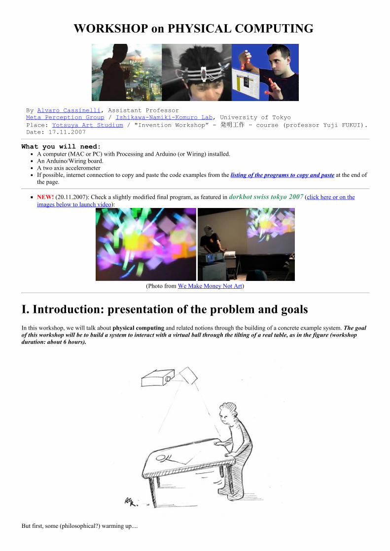
WORKSHOP on PHYSICAL COMPUTING
By Alvaro Cassinelli, Assistant ProfessorMeta Perception Group / IshikawaNamikiKomuro Lab, University of TokyoPlace: Yotsuya Art Studium / "Invention Workshop” 発明工作 – course (professor Yuji FUKUI). Date: 17.11.2007
What you will need:A computer (MAC or PC) with Processing and Arduino (or Wiring) installed.An Arduino/Wiring board.A two axis accelerometerIf possible, internet connection to copy and paste the code examples from the listing of the programs to copy and paste at the end ofthe page.
NEW! (20.11.2007): Check a slightly modified final program, as featured in dorkbot swiss tokyo 2007 (click here or on theimages below to launch video):
(Photo from We Make Money Not Art)
I. Introduction: presentation of the problem and goalsIn this workshop, we will talk about physical computing and related notions through the building of a concrete example system. The goalof this workshop will be to build a system to interact with a virtual ball through the tilting of a real table, as in the figure (workshopduration: about 6 hours).
But first, some (philosophical?) warming up....
Are we talking about a Virtual Reality system?
If we consider the table as just a humancomputer interface (like the mouse), and since the user is interacting with a computersimulated physical system and can see the result of the interaction on the computer screen, we can say that we are in front of anelementary example of a virtual reality system (featuring primarily realtovirtual world interaction, with visual feedback). Theimmersion in the simulated environment is of course minimal (the screen), but we could enhance this by using stereo vision, head trackingand a headmounted display.
Did you say Interaction Metaphor?
However, the interaction method suggests here that the virtual object actually sits on the real table; this is a compelling interactionmetaphor that facilitates the commanding of virtual objects. An interesting example of the use of such "gravity metaphor" (based on theprinciple that virtual and real spaces are both affected by the real gravity field) is for instance text scrolling on a PDA [2].
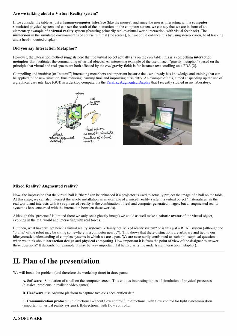
Compelling and intuitive (or “natural”) interacting metaphors are important because the user already has knowledge and training that canbe applied to the new situation, thus reducing learning time and improving efficiently. An example of this, aimed at speeding up the use ofa graphical user interface (GUI) in a desktop computer, is the Parallax Augmented Display that I recently studied in my laboratory.
Mixed Reality? Augmented reality?
Now, the impression that the virtual ball is "there" can be enhanced if a projector is used to actually project the image of a ball on the table.At this stage, we can also interpret the whole installation as an example of a mixed reality system: a virtual object "materializes" in thereal world and interacts with it (augmented reality is the combination of real and computer generated images, but an augmented realitysystem is less concerned with the interaction between these worlds).
Although this "presence" is limited (here we only see a ghostly image) we could as well make a robotic avatar of the virtual object,evolving in the real world and interacting with real forces…
But then, what have we got here? a virtual reality system? Certainly not. Mixed reality system? or is this just a REAL system (although the"brains" of the robot may be sitting somewhere in a computer nearby?). This shows that these distinctions are arbitrary and tied to ouridiosyncratic understanding of complex systems in which we are a part. We are necessarily confronted to such philosophical questionswhen we think about interaction design and physical computing. How important it is from the point of view of the designer to answerthese questions? It depends: for example, it may be very important if it helps clarify the underlying interaction metaphor).
II. Plan of the presentationWe will break the problem (and therefore the workshop time) in three parts:
A. Software . Simulation of a ball on the computer screen. This entitles interesting topics of simulation of physical processes(classical problems in realistic video games).
B. Hardware: use Arduino platform to capture twoaxis acceleration data
C. Communication protocol: unidirectional without flow control / unidirectional with flow control for tight synchronization(important in virtual reality systems). Bidirectional with flow control…
A. SOFTWARE
Where we will refresh Processing language key concepts.
The basic structure of a Processing program is: (a) prepare things, then (b) go into an "infinite loop" performing some task (presumablydrawing and acquiring data from the user). Each time you create a Processing/Arduino program for an interactive piece, you are creating astate machine whose inputs come from the “outside world”. Of course there are other paradigms for interactive systems (for example,interacting “agents” that run parallel threads on a computer and send messages to each other, event driven programs, data flowprogramming such as MAX/MSP… Note: Processing do has some event driven functions by the way).
However, since Processing is aimed at displaying and graphical animation, the “infinite loop” structure is very convenient because theexecution can be tightly coupled with the refreshing of the screen buffer (thus avoiding image jitter). Processing structure is very much likeC/C++ and OpenGL programming using the GLUT library (but way slower!). The former is what I used in Khronos Projector installation.Processing is an interpreted language, so it’s not the fastest out there… but can produce “applets” right away and run online!
void setup() size(700,500); // size of the displaying window void draw()
By just tapping this code and then executing it, Processing will open a small displaying window whose size can be retrieved at any time byreading the values of the reserved variables width and height (here width=700 and height=500).
Now, let’s start our application. The task can be divided into three phases:
1. Modeling the ball dynamics, including bouncing on the screen borders2. Defining the input interaction method3. Displaying the virtual object on the screen
(1) Modeling a ball that bounces on the borders of the screen.
In this example, we will simulate a ball that follows Newtonian dynamics. The fundamental law of Newtonian dynamics is of course:
For a planar motion, the ball dynamics is captured here using four variables (two 2D vectors): position R=(x,y) and velocity V=(vx, vy).Note that the force applied to the ball is given by the user (mouse or accelerometer), and is not a quantity that “belongs” to the ball;however, the acceleration is calculated using the mass of the ball. So the mass is another “intrinsic” ball variable. We also add the size ofthe ball, just for displaying purposes.
Ball “intrinsic” variables are:
Mass: m (a float)Position: x, y (a float)Speed: vx, vy (a float)Radius: ballRadius (in pixel: it’s a integer).
One can think about many more “intrinsic” parameters, such as spin, friction coefficient, elasticity, etc. The force is the “input” from theoutside world – discussed in (2). Once we know it, we can compute the acceleration (divining by the mass). The rest is inferred by the verydefinition of acceleration, speed and position:
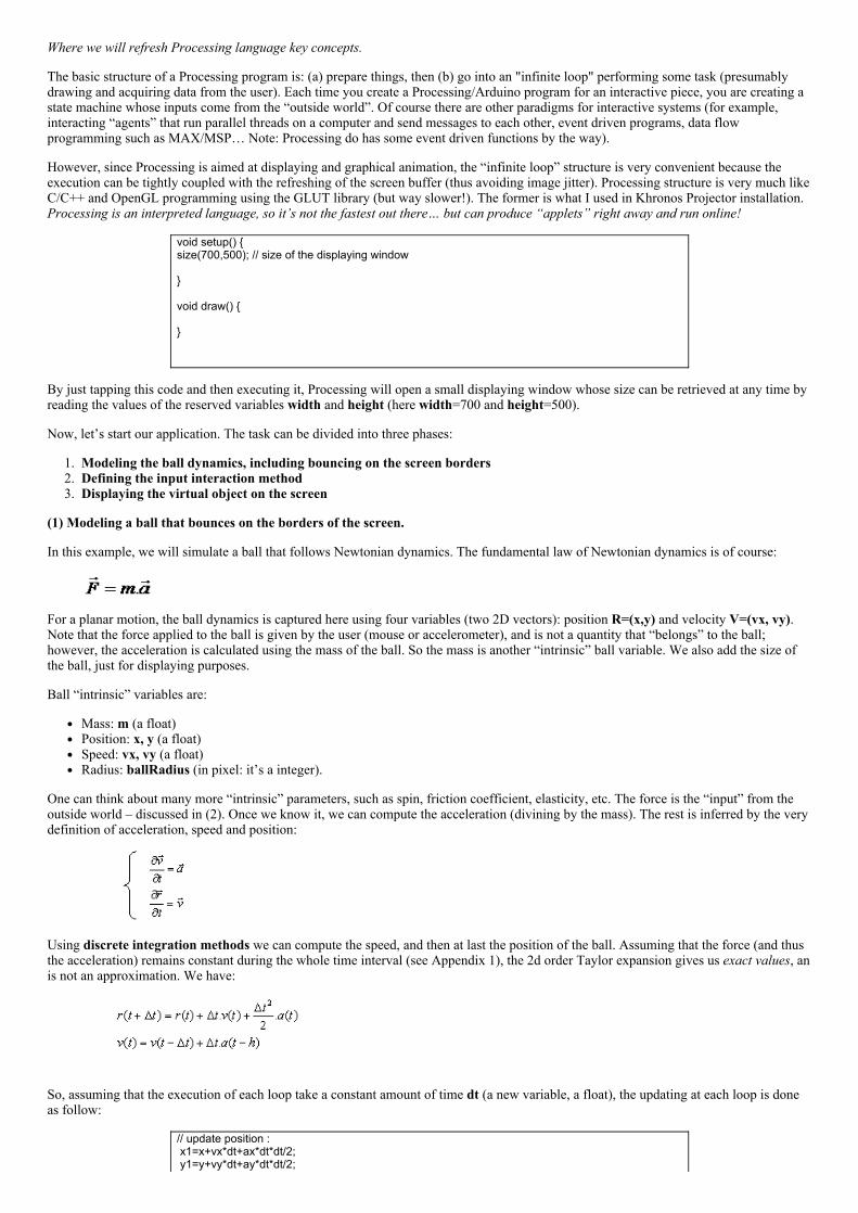
Using discrete integration methods we can compute the speed, and then at last the position of the ball. Assuming that the force (and thusthe acceleration) remains constant during the whole time interval (see Appendix 1), the 2d order Taylor expansion gives us exact values, anis not an approximation. We have:
So, assuming that the execution of each loop take a constant amount of time dt (a new variable, a float), the updating at each loop is doneas follow:
// update position : x1=x+vx*dt+ax*dt*dt/2; y1=y+vy*dt+ay*dt*dt/2;
//update speed : vx=vx0+ax*dt; vy=vy0+ay*dt;
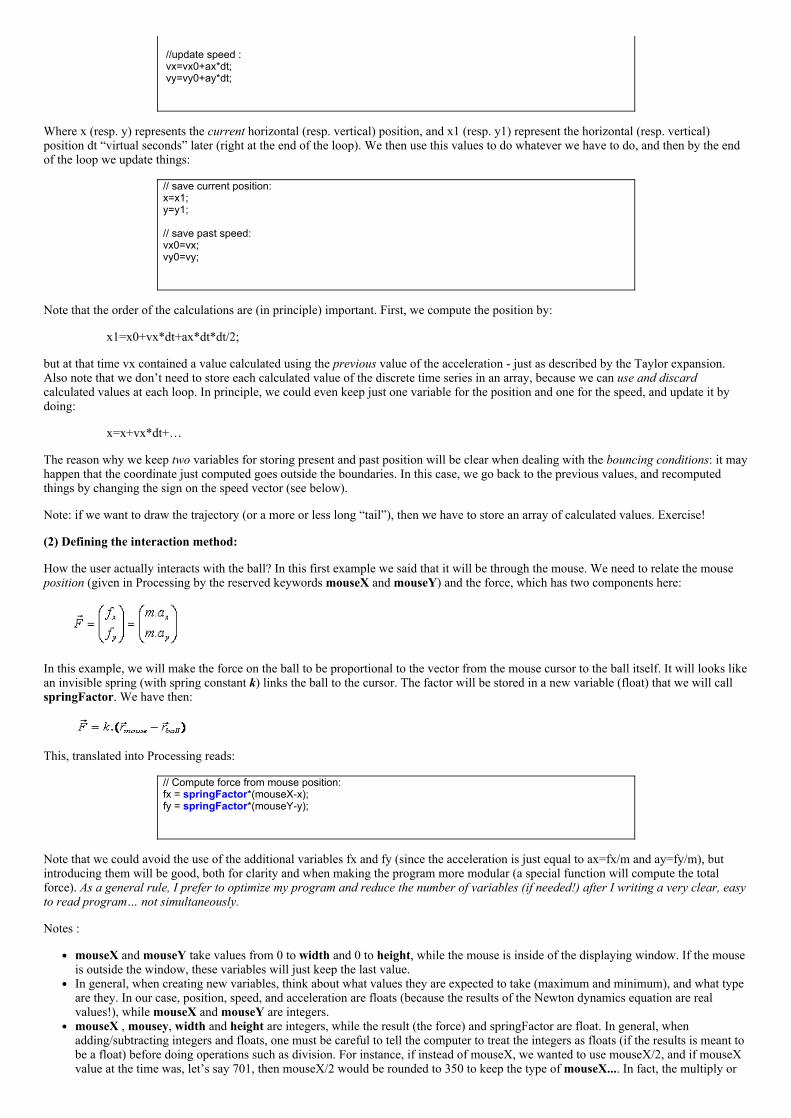
Where x (resp. y) represents the current horizontal (resp. vertical) position, and x1 (resp. y1) represent the horizontal (resp. vertical)position dt “virtual seconds” later (right at the end of the loop). We then use this values to do whatever we have to do, and then by the endof the loop we update things:
// save current position:x=x1;y=y1; // save past speed:vx0=vx;vy0=vy;
Note that the order of the calculations are (in principle) important. First, we compute the position by:
x1=x0+vx*dt+ax*dt*dt/2;
but at that time vx contained a value calculated using the previous value of the acceleration just as described by the Taylor expansion.Also note that we don’t need to store each calculated value of the discrete time series in an array, because we can use and discardcalculated values at each loop. In principle, we could even keep just one variable for the position and one for the speed, and update it bydoing:
x=x+vx*dt+…
The reason why we keep two variables for storing present and past position will be clear when dealing with the bouncing conditions: it mayhappen that the coordinate just computed goes outside the boundaries. In this case, we go back to the previous values, and recomputedthings by changing the sign on the speed vector (see below).
Note: if we want to draw the trajectory (or a more or less long “tail”), then we have to store an array of calculated values. Exercise!
(2) Defining the interaction method:
How the user actually interacts with the ball? In this first example we said that it will be through the mouse. We need to relate the mouseposition (given in Processing by the reserved keywords mouseX and mouseY) and the force, which has two components here:
In this example, we will make the force on the ball to be proportional to the vector from the mouse cursor to the ball itself. It will looks likean invisible spring (with spring constant k) links the ball to the cursor. The factor will be stored in a new variable (float) that we will callspringFactor. We have then:
This, translated into Processing reads:
// Compute force from mouse position:fx = springFactor*(mouseXx);fy = springFactor*(mouseYy);
Note that we could avoid the use of the additional variables fx and fy (since the acceleration is just equal to ax=fx/m and ay=fy/m), butintroducing them will be good, both for clarity and when making the program more modular (a special function will compute the totalforce). As a general rule, I prefer to optimize my program and reduce the number of variables (if needed!) after I writing a very clear, easyto read program… not simultaneously.
Notes :
mouseX and mouseY take values from 0 to width and 0 to height, while the mouse is inside of the displaying window. If the mouseis outside the window, these variables will just keep the last value.In general, when creating new variables, think about what values they are expected to take (maximum and minimum), and what typeare they. In our case, position, speed, and acceleration are floats (because the results of the Newton dynamics equation are realvalues!), while mouseX and mouseY are integers.mouseX , mousey, width and height are integers, while the result (the force) and springFactor are float. In general, whenadding/subtracting integers and floats, one must be careful to tell the computer to treat the integers as floats (if the results is meant tobe a float) before doing operations such as division. For instance, if instead of mouseX, we wanted to use mouseX/2, and if mouseXvalue at the time was, let’s say 701, then mouseX/2 would be rounded to 350 to keep the type of mouseX.... In fact, the multiply or
divide operators interpret operands as being the same type of the more precise of them (see Appendix 2). So, to force things tointerpret as floats, we would do: 1.0*mouseX/2.
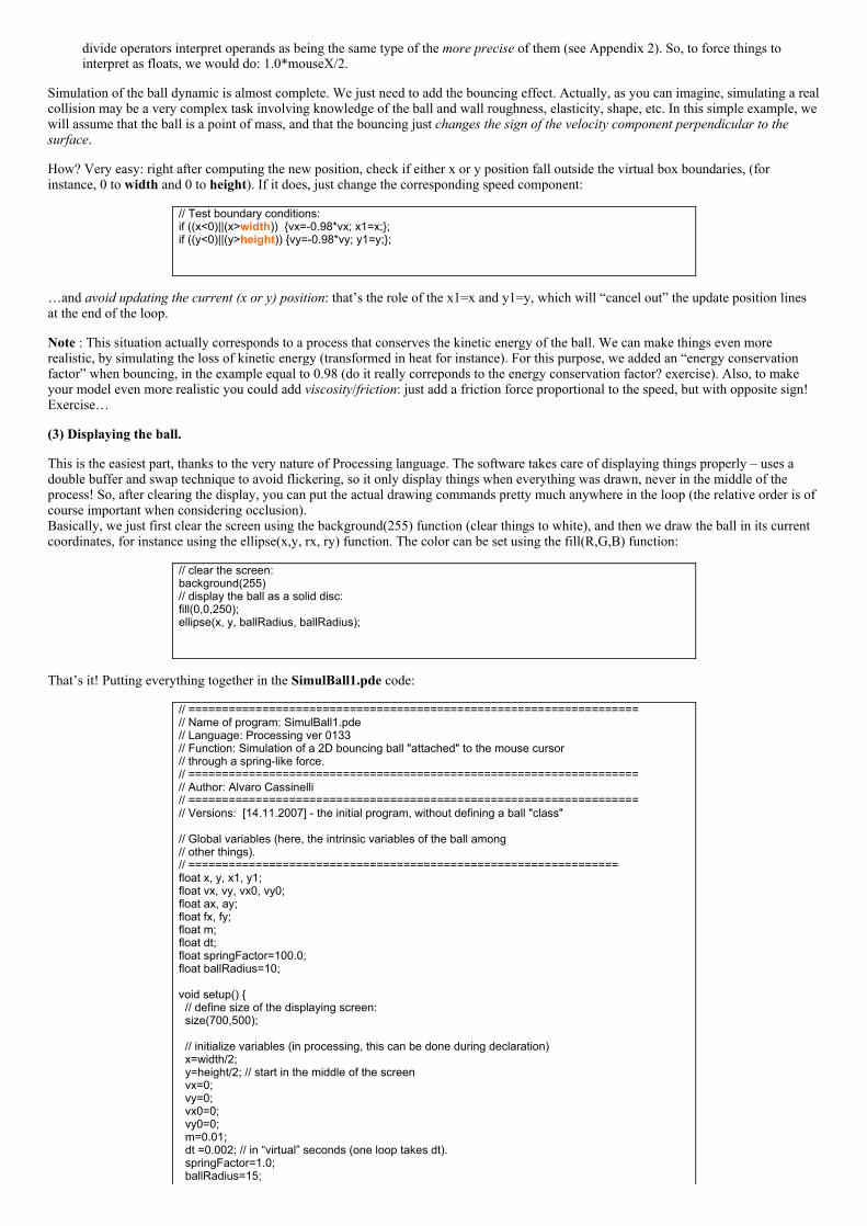
Simulation of the ball dynamic is almost complete. We just need to add the bouncing effect. Actually, as you can imagine, simulating a realcollision may be a very complex task involving knowledge of the ball and wall roughness, elasticity, shape, etc. In this simple example, wewill assume that the ball is a point of mass, and that the bouncing just changes the sign of the velocity component perpendicular to thesurface.
How? Very easy: right after computing the new position, check if either x or y position fall outside the virtual box boundaries, (forinstance, 0 to width and 0 to height). If it does, just change the corresponding speed component:
// Test boundary conditions:if ((x<0)||(x>width)) vx=0.98*vx; x1=x;;if ((y<0)||(y>height)) vy=0.98*vy; y1=y;;
…and avoid updating the current (x or y) position: that’s the role of the x1=x and y1=y, which will “cancel out” the update position linesat the end of the loop.
Note : This situation actually corresponds to a process that conserves the kinetic energy of the ball. We can make things even morerealistic, by simulating the loss of kinetic energy (transformed in heat for instance). For this purpose, we added an “energy conservationfactor” when bouncing, in the example equal to 0.98 (do it really correponds to the energy conservation factor? exercise). Also, to makeyour model even more realistic you could add viscosity/friction: just add a friction force proportional to the speed, but with opposite sign!Exercise…
(3) Displaying the ball.
This is the easiest part, thanks to the very nature of Processing language. The software takes care of displaying things properly – uses adouble buffer and swap technique to avoid flickering, so it only display things when everything was drawn, never in the middle of theprocess! So, after clearing the display, you can put the actual drawing commands pretty much anywhere in the loop (the relative order is ofcourse important when considering occlusion).Basically, we just first clear the screen using the background(255) function (clear things to white), and then we draw the ball in its currentcoordinates, for instance using the ellipse(x,y, rx, ry) function. The color can be set using the fill(R,G,B) function:
// clear the screen:background(255)// display the ball as a solid disc:fill(0,0,250);ellipse(x, y, ballRadius, ballRadius);
That’s it! Putting everything together in the SimulBall1.pde code:
// ===================================================================// Name of program: SimulBall1.pde// Language: Processing ver 0133// Function: Simulation of a 2D bouncing ball "attached" to the mouse cursor// through a springlike force.// ===================================================================// Author: Alvaro Cassinelli// ===================================================================// Versions: [14.11.2007] the initial program, without defining a ball "class" // Global variables (here, the intrinsic variables of the ball among// other things).// ================================================================float x, y, x1, y1;float vx, vy, vx0, vy0;float ax, ay;float fx, fy;float m;float dt;float springFactor=100.0;float ballRadius=10; void setup() // define size of the displaying screen: size(700,500); // initialize variables (in processing, this can be done during declaration) x=width/2; y=height/2; // start in the middle of the screen vx=0; vy=0; vx0=0; vy0=0; m=0.01; dt =0.002; // in “virtual” seconds (one loop takes dt). springFactor=1.0; ballRadius=15;
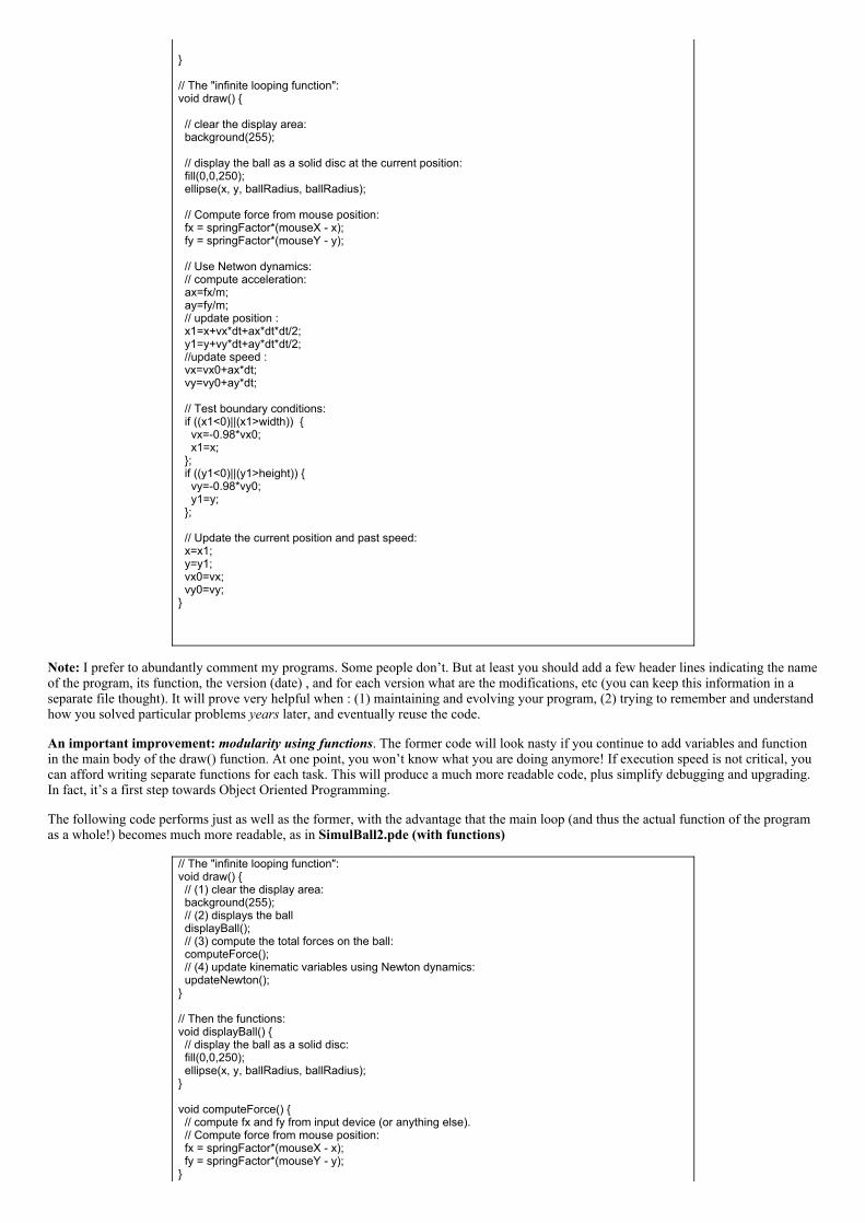
// The "infinite looping function":void draw() // clear the display area: background(255); // display the ball as a solid disc at the current position: fill(0,0,250); ellipse(x, y, ballRadius, ballRadius); // Compute force from mouse position: fx = springFactor*(mouseX x); fy = springFactor*(mouseY y); // Use Netwon dynamics: // compute acceleration: ax=fx/m; ay=fy/m; // update position : x1=x+vx*dt+ax*dt*dt/2; y1=y+vy*dt+ay*dt*dt/2; //update speed : vx=vx0+ax*dt; vy=vy0+ay*dt; // Test boundary conditions: if ((x1<0)||(x1>width)) vx=0.98*vx0; x1=x; ; if ((y1<0)||(y1>height)) vy=0.98*vy0; y1=y; ; // Update the current position and past speed: x=x1; y=y1; vx0=vx; vy0=vy;
Note: I prefer to abundantly comment my programs. Some people don’t. But at least you should add a few header lines indicating the nameof the program, its function, the version (date) , and for each version what are the modifications, etc (you can keep this information in aseparate file thought). It will prove very helpful when : (1) maintaining and evolving your program, (2) trying to remember and understandhow you solved particular problems years later, and eventually reuse the code.
An important improvement: modularity using functions. The former code will look nasty if you continue to add variables and functionin the main body of the draw() function. At one point, you won’t know what you are doing anymore! If execution speed is not critical, youcan afford writing separate functions for each task. This will produce a much more readable code, plus simplify debugging and upgrading.In fact, it’s a first step towards Object Oriented Programming.
The following code performs just as well as the former, with the advantage that the main loop (and thus the actual function of the programas a whole!) becomes much more readable, as in SimulBall2.pde (with functions)
// The "infinite looping function":void draw() // (1) clear the display area: background(255); // (2) displays the ball displayBall(); // (3) compute the total forces on the ball: computeForce(); // (4) update kinematic variables using Newton dynamics: updateNewton(); // Then the functions:void displayBall() // display the ball as a solid disc: fill(0,0,250); ellipse(x, y, ballRadius, ballRadius); void computeForce() // compute fx and fy from input device (or anything else). // Compute force from mouse position: fx = springFactor*(mouseX x); fy = springFactor*(mouseY y);
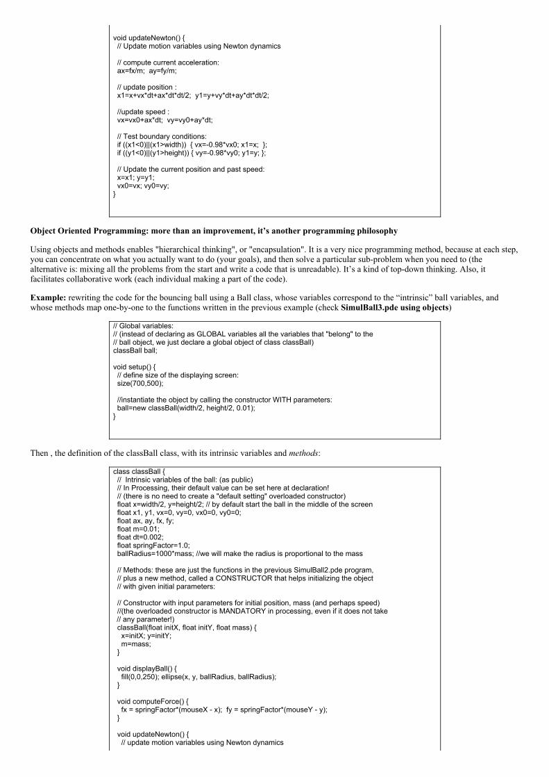
void updateNewton() // Update motion variables using Newton dynamics // compute current acceleration: ax=fx/m; ay=fy/m; // update position : x1=x+vx*dt+ax*dt*dt/2; y1=y+vy*dt+ay*dt*dt/2; //update speed : vx=vx0+ax*dt; vy=vy0+ay*dt; // Test boundary conditions: if ((x1<0)||(x1>width)) vx=0.98*vx0; x1=x; ; if ((y1<0)||(y1>height)) vy=0.98*vy0; y1=y; ; // Update the current position and past speed: x=x1; y=y1; vx0=vx; vy0=vy;
Object Oriented Programming: more than an improvement, it’s another programming philosophy
Using objects and methods enables "hierarchical thinking", or "encapsulation". It is a very nice programming method, because at each step,you can concentrate on what you actually want to do (your goals), and then solve a particular subproblem when you need to (thealternative is: mixing all the problems from the start and write a code that is unreadable). It’s a kind of topdown thinking. Also, itfacilitates collaborative work (each individual making a part of the code).
Example: rewriting the code for the bouncing ball using a Ball class, whose variables correspond to the “intrinsic” ball variables, andwhose methods map onebyone to the functions written in the previous example (check SimulBall3.pde using objects)
// Global variables:// (instead of declaring as GLOBAL variables all the variables that "belong" to the// ball object, we just declare a global object of class classBall)classBall ball; void setup() // define size of the displaying screen: size(700,500); //instantiate the object by calling the constructor WITH parameters: ball=new classBall(width/2, height/2, 0.01);
Then , the definition of the classBall class, with its intrinsic variables and methods:
class classBall // Intrinsic variables of the ball: (as public) // In Processing, their default value can be set here at declaration! // (there is no need to create a "default setting" overloaded constructor) float x=width/2, y=height/2; // by default start the ball in the middle of the screen float x1, y1, vx=0, vy=0, vx0=0, vy0=0; float ax, ay, fx, fy; float m=0.01; float dt=0.002; float springFactor=1.0; ballRadius=1000*mass; //we will make the radius is proportional to the mass // Methods: these are just the functions in the previous SimulBall2.pde program, // plus a new method, called a CONSTRUCTOR that helps initializing the object // with given initial parameters: // Constructor with input parameters for initial position, mass (and perhaps speed) //(the overloaded constructor is MANDATORY in processing, even if it does not take// any parameter!) classBall(float initX, float initY, float mass) x=initX; y=initY; m=mass; void displayBall() fill(0,0,250); ellipse(x, y, ballRadius, ballRadius); void computeForce() fx = springFactor*(mouseX x); fy = springFactor*(mouseY y); void updateNewton() // update motion variables using Newton dynamics
ax=fx/m; ay=fy/m; // update position : x1=x+vx*dt+ax*dt*dt/2; y1=y+vy*dt+ay*dt*dt/2; //update speed : vx=vx0+ax*dt; vy=vy0+ay*dt; // Test boundary conditions: if ((x1<0)||(x1>width)) vx=0.98*vx0; x1=x; ; if ((y1<0)||(y1>height)) vy=0.98*vy0; y1=y; ; // Update the current position and past speed: x=x1; y=y1; vx0=vx; vy0=vy;
Some great things about object programming:
you can create (i.e. "instantiate") as many of these objects as you want.code is reusable in other programs, and by other people, thanks to a proper documented "interface" (separate interface andimplementation files in C++)
Let’s see an example of the first advantage . Suppose that you want to create a hundred balls that evolve simultaneously on the screen.Imagine that you code this as in the very first example (everything as global variables, and with or without functions): for each variable ofthe ball, you will need to create now an array, and then in your program you will need to treat each ball sequentially, and take care ofsequentially addressing each variable for the corresponding ball. This is not incredible complicated in this example, but I bet that even inthis case you may make mistakes and scramble things easily. Look how easy it is to do the same using the Object Oriented Programmingparadigm (SimulBall4.pde, instantiating and using several objects simultaneously):
// Global variables: an ARRAY of particles, here 5classBall[] ball=new classBall[5]; void setup() // define size of the displaying screen: size(700,500); //instantiate ALL the particles, one by one, with different positions, radius and masses // rem: in this example, the radius is proportional to the mass (see the constructor!) for (int i=0; i<5; i++) ball[i]=new classBall(random(0,width),random(0,height),random(0.01,0.09)); // The "infinite looping function":void draw() // clear the display area: background(255); // now, for treat the balls sequentially: for (int i=0; i<5; i++) // displays the ball with index i in the object array: ball[i].displayBall(); // compute the total forces on the ball with index i in the object array: ball[i].computeForce(); // update kinematic variables of ball with index i in the object array: ball[i].updateNewton();
… and that’s all!! You don’t have to touch a thing in the class definition!! Beautiful, isn’it? That will do for our minimal incursion in thefantastic world of object oriented programming..
B. Hardware:
Use Arduino/Wiring platform to capture information from a twoaxis acceleration data. I assume that you know how to acquire data usingthe Arduino/Wiring platform. Here, we will just read two analog values from an accelerometer, so the code is extremely simple.
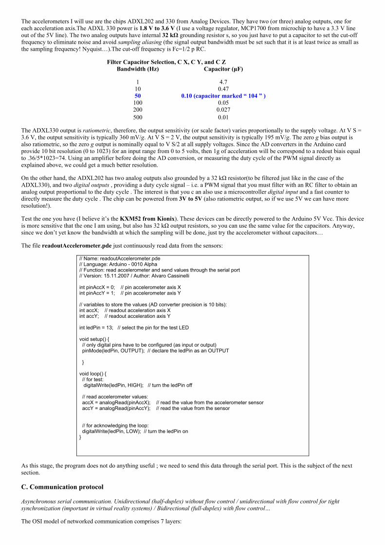
The accelerometers I will use are the chips ADXL202 and 330 from Analog Devices. They have two (or three) analog outputs, one foreach acceleration axis.The ADXL 330 power is 1.8 V to 3.6 V (I use a voltage regulator, MCP1700 from microchip to have a 3.3 V lineout of the 5V line). The two analog outputs have internal 32 kΩ grounding resistor s, so you just have to put a capacitor to set the cutofffrequency to eliminate noise and avoid sampling aliasing (the signal output bandwidth must be set such that it is at least twice as small asthe sampling frequency! Nyquist…).The cutoff frequency is Fc=1/2 p RC.
Filter Capacitor Selection, C X, C Y, and C ZBandwidth (Hz)
1
Capacitor (μF)
4.710 0.4750 0.10 (capacitor marked “ 104 ” )100 0.05200 0.027500 0.01
The ADXL330 output is ratiometric, therefore, the output sensitivity (or scale factor) varies proportionally to the supply voltage. At V S =3.6 V, the output sensitivity is typically 360 mV/g. At V S = 2 V, the output sensitivity is typically 195 mV/g. The zero g bias output isalso ratiometric, so the zero g output is nominally equal to V S/2 at all supply voltages. Since the AD converters in the Arduino cardprovide 10 bit resolution (0 to 1023) for an input range from 0 to 5 volts, then 1g of acceleration will be correspond to a redout biais equalto .36/5*1023=74. Using an amplifier before doing the AD conversion, or measuring the duty cycle of the PWM signal directly asexplained above, we could get a much better resolution.
On the other hand, the ADXL202 has two analog outputs also grounded by a 32 kΩ resistor(to be filtered just like in the case of theADXL330), and two digital outputs , providing a duty cycle signal – i.e. a PWM signal that you must filter with an RC filter to obtain ananalog output proportional to the duty cycle . The interest is that you c an also use a microcontroller digital input and a fast counter todirectly measure the duty cycle . The chip can be powered from 3V to 5V (also ratiometric output, so if we use 5V we can have moreresolution!).
Test the one you have (I believe it’s the KXM52 from Kionix). These devices can be directly powered to the Arduino 5V Vcc. This deviceis more sensitive that the one I am using, but also has 32 kΩ output resistors, so you can use the same value for the capacitors. Anyway,since we don’t yet know the bandwidth at which the sampling will be done, just try the accelerometer without capacitors…
The file readoutAccelerometer.pde just continuously read data from the sensors:
// Name: readoutAccelerometer.pde// Language: Arduino 0010 Alpha// Function: read accelerometer and send values through the serial port// Version: 15.11.2007 / Author: Alvaro Cassinelli int pinAccX = 0; // pin accelerometer axis Xint pinAccY = 1; // pin accelerometer axis Y // variables to store the values (AD converter precision is 10 bits):int accX; // readout acceleration axis Xint accY; // readout acceleration axis Y int ledPin = 13; // select the pin for the test LED void setup() // only digital pins have to be configured (as input or output) pinMode(ledPin, OUTPUT); // declare the ledPin as an OUTPUT void loop() // for test: digitalWrite(ledPin, HIGH); // turn the ledPin off // read accelerometer values: accX = analogRead(pinAccX); // read the value from the accelerometer sensor accY = analogRead(pinAccY); // read the value from the sensor // for acknowledging the loop: digitalWrite(ledPin, LOW); // turn the ledPin on
As this stage, the program does not do anything useful ; we need to send this data through the serial port. This is the subject of the nextsection.
C. Communication protocol
Asynchronous serial communication. Unidirectional (halfduplex) without flow control / unidirectional with flow control for tightsynchronization (important in virtual reality systems) / Bidirectional (fullduplex) with flow control…
The OSI model of networked communication comprises 7 layers:

Application / Presentation / Session / Transport / Network / DataLink / Physical
Keep in mind that the only real interest of this subdivision is to separate different communications subsystems to simplifydebugging/upgrading process (hardware and software), very much like when you program using functions (or objects). Whenmodifying one subsystem, if it performs exactly as specified by the OSI standards, then there is no need to touch anything in the rest of thesystem.
In this workshop we will talk concentrate on serial communications (i.e., sending data one bit at a time over the communication channel).Serial communication can be synchronous or asynchronous. Asynchronous serial communication is used in RS232, USB, FireWire, Midi ,Ethernet…We will concentrate on this. Serial communication is a “lowlevel” protocol, and most certainly we won’t need to implement allthe OSI layer. A more adequate subsystem subdivision for implementing/debugging this communication protocol may be the following(proposed in Tom Igoe’s fantastic book "Making things talk"):
Physical: connection pins (how many, how are they connected).Electrical: electrical voltage levels usedLogical: mapping between voltage level and logical bitData: are bits sent in groups (frames) of bytes? Big or Little Endianness? Timing of bits? [OSI: transport layer / network layer anddata link layer].Application: the thing that you really have to deal with! How the bits/bytes are arranged in messages? Packets? How you read andinterpret the packet data? Is there flowcontrol or not (handshake)?
Now, as you may know the Atmel microcontroller chip (in the Wiring/Arduino board) has two pins (RX/TX) and implements the TTLSerial Protocol, while the modern PCs “speaks” USB serial! How they can communicate? Thanks to a serial to USB converter, that isembedded in the Arduino/Wiring board (the “FTDI” USBtoSerial adaptor chip). Of course, if you use an old PC with an RS232connector, then both side will be talking TTL serial, and you can directly connect the Arduino RX pin to the “receive” pin (pin 2) of theRS232 connector, the TX pin of the Arduino to the “transmit” pin of the connector (pin 3), and the Arduino GND to the pin 5 of theconnector (the PC ground). If you use the USB based Arduino, which you probably do, then both sides are talking a slightly different serialprotocol:
Arduino side: TTL SERIAL
Physical: The Atmel microcontroller has two pins, labeled RX and TX for this. In the Arduino, these are digital pins 0 and 1 (if youuse the serial communication, you cannot use these pins for other purposes).Electrical: electrical voltage levels: TTL (05V).Logical: mapping between voltage level and logical bit: 0V = 0, 5V=1.Data: the data rate can be set by the user (ex: 9600 bits/s), the unit of transmission is an 8 bits long frame (preceded by a start and anend bit, but this is not seen by the application).
Application: from the Arduino side, you will use the following commands to write your own application layer communication protocol:
Serial.begin(speed)int Serial.available()int Serial.read()Serial.flush()Serial.print(data, format)Serial.println(data, format)
I will explain each command during the workshop; but the most important thing to remember is that when you write (using Serial.print) orread data (using Serial.read), you will read a data unit, which as we said is a group of 8 bits (so the “minimum” type of the variable to storethis data can be a char or a byte).
PC/MAC side: USB SERIAL
Physical: The Atmel microcontroller has two pins, labeled RX and TX for this. In the Arduino, these are digital pins 0 and 1 (if youuse the serial communication, you cannot use these pins for other purposes).Electrical: electrical voltage levels: TTL (05V).Logical: mapping between voltage level and logical bit: 0V = 0, 5V=1.Data: the data rate can be set by the user (ex: 9600 bits/s), the unit of transmission is an 8 bits long frame (preceded by a start and anend bit, but this is not seen by the application).Application: from the MAC/PC side with Processing installed, you will use commands provided by the Serial library to write yourown application layer communication protocol. These commands are in fact methods of the Serial class:
Serial methods:
Serial,available()read()readChar()readBytes()readBytesUntil()readString()readStringUntil()buffer()bufferUntil()last()
lastChar()write()clear()stop()list()
Serial events
serialEvent()
CREATING YOUR OWN DATA PROTOCOL:
The way we decide to send/receive the data can be more or less arbitrary: in fact, you can create the data protocol of our choice. In ourexample, there are two values to be sent to the computer, and you must somehow separate each of them. I won’t go into much detail here;ideally you could create a complete PACKET of data, with a header, a tail (indicating the termination of the packet), and SEPARATORSbetween each unit of data in the PAYLOAD):
START XXX , XXX , XXX STOP
The interest of this structure is that:
The packet can be discarded if we missed the START code. This helps “align” with the data.We can also use specific separators (not just the “,”) to indicate the meaning of each value XXX (e.g., which sensor has been read),eliminating the need to send packets always the same length. This can speed up things (suppose you are reading tens of sensors, youmay want to send the data only for those whose reading has changed).And most important: the units of data (XXX) can be of an arbitrary length (in bytes), because we can know when to
In fact, there is no ideal data protocol that would satisfy all the possible communication needs. It really depends on your goals: speed?flexibility? readability (for a human user that would check data on a serial monitor window?...
IMPORTANT NOTES:
Each sensor value can be sent as raw binary data (a byte or several bytes), or as ASCII data (sending the sequence of ASCII codes ofthe decimal or hexadecimal representation of the number).The later approach is more appropriate in many cases; in particular, it allows the use of header, tail and delimiters codes! (It canhappen for instance that the reading of the accelerometer is 44, which in fact correspond to ASCII “,” which we have been using as adelimiter!)Another interest of sending data as ASCII is that a human user can use a serial monitor (as the one provided in the Arduino/WiringIDE) to check the values directly in decimal or hexadecimal representation.
In our case, let’s stick to the simplest possible protocol for sending two values:
XXX , XXX STOP
The sensor values will be sent as ASCII codes of the DECIMAL representation of the number. The delimiter “,” will tell us which value iswhich (X or Y acceleration). The STOP code (for instance \r , i.e., carriage return) enables us to ALIGN to the data (otherwise, we wouldnot be able to tell which value correspond to which sensor: XXX, XXX, XXX, XXX, …)
Notes:
the PC and the Arduino/Wiring board can talk in a fullduplex manner (i.e, both writing messages over the communication channelat the same time), because (1) there are separated pins for sending and receiving (physical layer) and there is specialized hardware todeal with buffering of frames in both sides of the communication system (probably in the data layer...).From the perspective of the data protocol, it is important to note that there is no need to have the SAME coding/decoding structureand protocol for communications in one or the other side; however, BOTH sides must know how to read and how to talk to the other.All these specifications form the data protocol of the fullduplex communication.
Now we are ready and we can write the code both on the Arduino/Wiring and the Processing sides. Let’s start with the Arduino side:
(1) Sending data from the Arduino/Wiring side:
The program that we wrote in the previous section (readAccelerometer.pde) must be modified. First, you need to add a line to initializethe serial communication in the setup function (you can find the modified code in the file readAndSendAccelerometer.pde):
void setup() // only digital pins have to be configured (as input or output) pinMode(ledPin, OUTPUT); // declare the ledPin as an OUTPUT Serial.begin(9600); // opens serial port, sets data rate to 9600 bps
Then, add a function to send data in the main loop:
void loop() // for test:
digitalWrite(ledPin, HIGH); // turn the ledPin off // read accelerometer values: accX = analogRead(pinAccX); // read the value from the accelerometer sensor accY = analogRead(pinAccY); // read the value from the sensor //Send values through the serial port: sendData(); // A pause is perhaps necessary in case of communication without handshake, // to avoid saturating the serial buffer at the PC side: delay(100); // delay in milliseconds // for acknowledging the loop: digitalWrite(ledPin, LOW); // turn the ledPin on void sendData() Serial.print(accX, DEC); Serial.print(","); Serial.println(accY, DEC);
Note that the sendData() function follows our previous specification for the communication protocol. Before going further, you could checkthat things are working well by monitoring the serial input on the serial monitor of the Arduino IDE.
Note : Byte order or endianness of the serial communication. If you send an array of bytes or a string, such as Serial.write(1234, DEC) ,then the FIRST byte (char) sent through the serial will be “4”, then “3”, “2” and finally “1”. As for the endianness of the bits sent throughthe serial port, you don’t have to deal with because it is taken care at the data protocol layer (i.e., if you send a byte from the Arduino side,you always receive a byte from the Processing side, which is not “flipped”).
(2) Processing side:
import processing.serial.*;Serial serialPort; void setup() //… serialPort = new Serial(this, "COM3", 9600);
The first thing to do is to include the serial library (“importing” it in Java jargon) at the beginning of your code. Then declare a globalvariable of class type Serial, and then, in the Setup() function you have to instantiate an object of this class passing the proper values suchas serial port name and data rate (the default constructor will open the port for you):
Then, there are basically two methods to acquire data from the serial port:
One is called continuous polling, and consist on checking the bytes awaiting in the serial buffer every time the program loops in thedraw function;The other is using interruptions, i.e. eventdriven calls to specific functions. This method is more advanced and may saveprocessing time, in particular when you set the event to be triggered only when the buffer receives a special code such as the STOPcode of course.
I will use the later method in the program below, but I must say that recently (10.11.2007) I discovered a malfunction on the serialEventfunction in the latest version of Processing (0133) that makes this method no better than the continuous polling: the callback is placedevery time something – anything – appears in the buffer. This malfunction is invisible in the code below because we doubletest that all thedata has arrived using serialPort.readStringUntil…
First, add this line right after opening the serial port (in the setup function):
// Set the trigger for the serialEvent function: a call to this function will be placed whenever the buffer// receives a carriage return code: serialPort.bufferUntil(10); // 10 is the ASCII code of the carriage return.
Then, add a function that will process the content of the serial buffer each time time the ASCII code 10 is received (in principle, this iswhat the function should be doing!!):
void serialEvent(Serial serialPort) // read the string in the buffer until it finds a special character String myString=serialPort.readStringUntil(10); // 10 is carriage return ASCII code if (myString != null) // this shouldn't be necessary if bufferUntil was working okay!
myString=trim(myString); // takes away the spaces and carriage return codes //split the string at the commas (our packet delimiters) and convert the // decimal, ASCII coded numbers into integers:
int data[] = int(split(myString, ',')); // check if we received all the data (we could have started from the second value...) if (data.length==2) // assign the read value to the global force, using a special conversion function: globalFx=convertData(data[0], 5000, 327, 263, 396); globalFy=convertData(data[1], 5000, 326, 265, 403);
The conversion function is a very important function: it relates the real world measurements to the virtual world quantities. It’s a bridgebetween worlds and you have to take care that it does the job properly. This means that you will need to experiment quite a bit until you getthe right values for the conversion (it can be just a linear operation involving an offset and a gain, but it can also imply logarithms andperhaps much more complicated operations, which may involve knowledge on psychophysics for instance). In our case, we will do just abasic linear operation:
// convert the value read from the accelerometer to the force on the ball:float convertData(int value, float gain, int offset, int minvalue, int maxvalue) float force; force=1.0*gain*(valueoffset)/(maxvalueminvalue); return(force);
The arguments to the function are respectively the Gain factor, the offset (i.e., the value measured when the accelerometer is horizontal forinstance), then the minimum and maximum sensor readout. You can check all these values by opening the serial monitor in the ArduinoIDE and trying different positions for the accelerometer. However, in advanced versions of this program you could do this workautomatically, and/or display these values on the Processing window.
Note: even if you perform some calculations beforehand, you will need to adjust the parameters to get the “best looking / best feeling”dynamics and interaction. This is an extremely important (and sometimes time consuming) phase. Don’t overlook it! The nice thing aboutit (as well as when you are coding your program for the first time and make unexpected errors) is that you can also discover newpossibilities, and get new ideas you didn’t think about before. Be alert, and don’t miss what the computer (bugs) may bring you as a gift!
Finally, change the way the acceleration is calculated for each ball in the updateNetwon method of the class classBall, by using the globalvariable forceFx and forceFy:
// compute current acceleration, using the GLOBAL FORCE: ax=globalFx/m; ay=globalFy/m;
B) Unidirectional communication with flow control (Handshake)
In fact, this application protocol implements an unidirectional communication without flow control. If you try the complete systemArduino+Processing (try it!), you may notice some random delays between the action and the response in the virtual environment. Thereason (one of the reasons at least) is that we have overlooked the fact that the Arduino board can continuously sends data at a sufficientlyhigh pace, and if Processing does not read (because it cannot or don’t need to) these bytes at the same rate, then the serial buffer (at the PCside) may be filled until it is full and bytes sent by the Arduino board will be lost. Even if loosing some bytes is not important (this may bethe case if the unit of information you are sending is a byte), Processing may be reading data that is a little outdated (the serial buffer in thePC side is a couple thousand bytes long) .
The solution is to implement a form of flowcontrol known as handshake (or synchronous communication) between both sides. In it’ssimplest form, the handshake protocol is: only send data when the Processing program actually request it! (check SimulBall6.pde). First,we will define a binary flag (i.e. a Booleantype variable) to make the program “remember” if it has sent a request, and if this request hasbeen answered. If not, then don’t issue a new request (but don’ wait! Just ignore things and continue drawing the balls):
// a FLAG to avoid sending request if we didn't receive a (complete) answer yetboolean can_Talk=true;
Then, add somewhere in the guts of the draw function the following code:
// send a request to read sensor data (only if we "can talk" again, because we already // diggested the complete answer from the microcontroller! if (can_Talk==true) can_Talk=false; serialPort.write(10); // just send anything (here a carriage return...)
Finally, when the request has been answered, we have to reset the flag to true, meaning that we will now be able to issue new requests.This is done by modifying the serialEvent function, and setting can_Talk flag to true if the answer from the microcontroller was completeand well received:
…// now, check if we actually received all the data! (we could have been reading from the secondvalue...) if (data.length==2)
// assign the read value to the global force, using a special conversion function globalFx=convertData(data[0], 5000, 327, 263, 396);
globalFy=convertData(data[1], 5000, 326, 265, 403); // if we got here, it means that the answer was complete and well received; // we can reset the can_Talk flag to true, so we can issue new requests: can_Talk=true; …
It’s not over: we still have to “enslave” the Arduino microcontroller, making the program less talkative and more obedient. The Arduinomust only send data to the serial port when the Processing program send s a request code (here anything on the serial buffer). This is verysimple; we just need to check if something is in the serial buffer ( readHandShake.pde). This is done adding these few commands in themiddle of the Arduino loop:
//Send values through the serial port when requested: if (Serial.available()>0) sendData(); Serial.read(); // we have to clear at least ONE byte (= one request!)
… and then you can also get rid of the delay(100): if things go as planned, the serial buffer (at the PC side) will never be overloaded!
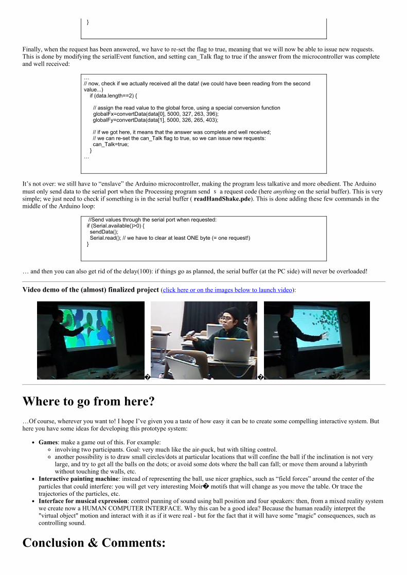
Video demo of the (almost) finalized project (click here or on the images below to launch video):
Where to go from here?…Of course, wherever you want to! I hope I’ve given you a taste of how easy it can be to create some compelling interactive system. Buthere you have some ideas for developing this prototype system:
Games: make a game out of this. For example:involving two participants. Goal: very much like the airpuck, but with tilting control.another possibility is to draw small circles/dots at particular locations that will confine the ball if the inclination is not verylarge, and try to get all the balls on the dots; or avoid some dots where the ball can fall; or move them around a labyrinthwithout touching the walls, etc.
Interactive painting machine: instead of representing the ball, use nicer graphics, such as “field forces” around the center of theparticles that could interfere: you will get very interesting Moir motifs that will change as you move the table. Or trace thetrajectories of the particles, etc.Interface for musical expression: control panning of sound using ball position and four speakers: then, from a mixed reality systemwe create now a HUMAN COMPUTER INTERFACE. Why this can be a good idea? Because the human readily interpret the"virtual object" motion and interact with it as if it were real but for the fact that it will have some "magic" consequences, such ascontrolling sound.
Conclusion & Comments:
Many tutorials end by the words “get creative”. I find this a little curious since if you are here now, it means that you have (or had) at leastsome ideas that you want (or wanted) to implement; I mean, it’s good to learn how to interconnect things and “get inspired” by the handson workshop, but this may not always lead to the idea up there! Of course it can be pleasurable to do some hacking, but it may be a littlefrustrating to end up doing again thelittlerobotthatwalksandbumpsintothewalls, and that’s it! (it only impresses you because youknow what’s “inside” I know what I am talking about! ;). Seriously, I encourage you to think first about what you want to do, play withthe idea for a while in your mind, eventually talk with other people and always think as if the implementation was not a problem. Thinkwithout limits during that phase. If your idea resist brainstorming (and/or evolve from them), then it may be worth putting all your energyon it!
… and once you are at it, don’t think too much: just do it. If you keep looking around, you may never finish your homework! By the way,it is very likely that someone out there is doing something very similar: there is nothing to worry about (if you have been ethical in yourapproach of course!), for if you are putting your passion, the result of your effort will be a true contribution to the field.
References and Recommended books (to be completed later)Books:
“Making things talk” by Tom Igoe . I recently discovered this fantastic book that introduces you to the world of physicalcomputing in a really smooth and enjoyable way. GET IT. Basically, after reading it you will be able to do anything involvingmicrocontrollers, sensors and networked devices (wifi, Bluetooth, internet, etc…).
Other references
[1] http://en.wikipedia.org/wiki/Discrete_element_method
[2] Poupyrev, I. , S. Maruyama, and J. Rekimoto. Ambient Touch: Designing tactile interfaces for handheld devices.Proceedings of UIST'2002. 2002: ACM: pp. 5160 (http://www.sonycsl.co.jp/person/rekimoto/papers/uist96.pdf). Check also:Jun Rekimoto, "Tilting Operations for Small Screen Interfaces", User Interface and Software Technology (UIST'96), 1996.(http://www.sonycsl.co.jp/person/rekimoto/papers/uist96.pdf)
Appendix 1 : The assumption that the force is constant during the discrete time interval (implying that the mouse is considered to freezeevery dt) may be okay in our exercise, but one has to remember that any discrepancy between the simulation and the expected outcome canbe readily noticeable by the human user, reducing the effectiveness of the immersion (and even producing VR “sickness”). However, if theacceleration changes slowly (i.e., the mouse moves slowly) at the time scale of dt, then the Taylor expansion, although not exact, will be agood approximation. We can even use the “Euler integration method”, which is based on a first order Taylor expansion leading to:
In any case, error may cumulate and the trajectory will diverge with respect to the “real” trajectory. In general, exact results using discreteintegration when the acceleration is a continuous function and/or depend on position or speed (this is, the equation we try to solve is adifferential equation) is not possible. This is the case in particular when there are interparticle forces (acceleration depends on relativeposition of particles) or when there is friction (acceleration depends on the speed). Discrete approximation methods for solving differentialequations is a complex topic; it’s actually a whole field (in which there is still a lot of research), called Discrete Elements Methods (DEM)as is essential to the fields of simulational physics, biochemistry, astrophysics, engineering… and ultrarealistic simulations in computergames!
Appendix 2: Converting an expression of a given type into another type is known as typecasting, and may be required in languages thatare strongtyped, such as C. Failing to do that properly lead to many errors difficult to debug. The Processing language is doing dynamictype casting on the parser tree, and it’s not very clear to me how it does it in fact! (1.0+2/3 = 1.0, but 1+2.0/3 = 1.6666…)
Listing of the programs to copy and paste during the workshop:Processing files:
SimulBall1.pde : simulation of a bouncing ball, all the code in the loop function. Mouse control.
SimulBall2.pde : + using functions
SimulBall3.pde : + using objects
SimulBall4.pde : + several objects
SimulBall5.pde : instead of mouse, control comes from accelerometer readout [Arduino side:

readAndSendAccelerometer.pde]
SimulBall6.pde : same as SimulBall5, but with handshake [Arduino side: readHandShake.pde]
Arduino/Wiring files:
readoutAccelerometer.pde : simulation of a bouncing ball, all the code in the loop function. Mousecontrol.
readAndSendAccelerometer.pde: send accelerometer data through serial port (goes withSimulBall5.pde)
readHandShake.pde : + handshake (goes with SimulBall6.pde)