Embed Size (px)
Citation preview

1 Gearheads
CSF-GH Gearhead Series
HPG
Serie
sHi
gh-P
erfo
rman
ce G
earh
ead
for S
ervo
mot
ors
HPG
Serie
sHi
gh-P
erfo
rman
ce G
earh
ead
for S
ervo
mot
ors
High
-Per
form
ance
Gea
rhea
d fo
r Ser
vom
otor
s
High
-Per
form
ance
Gea
rhea
d fo
r Ser
vom
otor
s HP
GP S
eries
HPGP
Ser
ies
High
-Per
form
ance
Gea
rhea
d fo
r Ser
vom
otor
s
High
-Per
form
ance
Gea
rhea
d fo
r Ser
vom
otor
s
CSG-
GH S
eries
CSG-
GH S
eries
High
-Per
form
ance
Gea
rhea
d fo
r Ser
vom
otor
s
High
-Per
form
ance
Gea
rhea
d fo
r Ser
vom
otor
s
High
-Per
form
ance
Gea
rhea
d fo
r Ser
vom
otor
s
High
-Per
form
ance
Gea
rhea
d fo
r Ser
vom
otor
s
CSF-
GH S
eries
CSF-
GH S
eries
High
-Per
form
ance
Gea
rhea
d fo
r Ser
vom
otor
s
High
-Per
form
ance
Gea
rhea
d fo
r Ser
vom
otor
s
CSF-
GH S
eries
CSF-
GH S
eries
HPG
Righ
t Ang
le
HPG
Righ
t Ang
le
Size14, 20, 32, 45, 65 Sizes
5
Zero backlash
High AccuracyRepeatability ±4 to ±10 arc-sec
Peak torque18Nm to 2630Nm
Reduction ratio50:1 to 160:1
CSF-GH Standard Series
Gearhead ConstructionFigure 076-1
(The figure indicates output shaft type.)
Mounting pilotGrease filling port
(2 locations)Output Shaft (flange optional)
Output rotational direction
Oil sealCross roller bearing
Mounting bolt hole Motor mounting flange
Input rotational direction
Shielded bearing
Rubber cap
Quick Connect™ coupling
C O N T E N T SRating Table, Ratcheting Torque, Buckling Torque……………..2Performance Table…………………………………………….. 3Torsional Stiffness ……………….….…………….………….. 4Outline Dimensions……………………………………….......5-9Rating Table Definitions, Life, Torque Limits………………11-12Torsional Stiffness, Vibration, Efficiency…………………..13-14Product Sizing & Selection………………. ………………. 15-16
CSF
Reduction RatioSizeModel Name
CSFStandard
Output Configuration Input Configuration
1420324565
50, 80, 100
50, 80, 100, 120, 160
80, 100, 120, 160
Model
GH: Gearhead
20 100 GH F0- - - -
F0: Flange outputJ2: Straight shaft (without
key)J6: Straight shaft (with key
and center tapped hole)
This code represents the motor mounting configuration. Please contact us for a unique part number based on the motor you are using.
Motor Model Number
Quick Connect™ coupling
A Cross Roller bearing is integrated with the output flange to provide high moment stiffness, high load capacity and precise positioning accuracy.
High Load Capacity Output Bearing
Easy mounting to a wide variety of servomotors
ELECTROMATEToll Free Phone (877) SERVO98
Toll Free Fax (877) SERV099www.electromate.com
Sold & Serviced By:

2Gearheads
CSF-GH Gearhead Series
HPG
Serie
sHi
gh-P
erfo
rman
ce G
earh
ead
for S
ervo
mot
ors
HPG
Serie
sHi
gh-P
erfo
rman
ce G
earh
ead
for S
ervo
mot
ors
High
-Per
form
ance
Gea
rhea
d fo
r Ser
vom
otor
s
High
-Per
form
ance
Gea
rhea
d fo
r Ser
vom
otor
s HP
GP S
eries
HPGP
Ser
ies
High
-Per
form
ance
Gea
rhea
d fo
r Ser
vom
otor
s
High
-Per
form
ance
Gea
rhea
d fo
r Ser
vom
otor
s
CSG-
GH S
eries
CSG-
GH S
eries
High
-Per
form
ance
Gea
rhea
d fo
r Ser
vom
otor
s
High
-Per
form
ance
Gea
rhea
d fo
r Ser
vom
otor
s
High
-Per
form
ance
Gea
rhea
d fo
r Ser
vom
otor
s
High
-Per
form
ance
Gea
rhea
d fo
r Ser
vom
otor
s
CSF-
GH S
eries
CSF-
GH S
eries
High
-Per
form
ance
Gea
rhea
d fo
r Ser
vom
otor
s
High
-Per
form
ance
Gea
rhea
d fo
r Ser
vom
otor
s
CSF-
GH S
eries
CSF-
GH S
eries
HPG
Righ
t Ang
le
HPG
Righ
t Ang
le
14 20 32 45 65
5080
100120160
8811084——
220350260240220
98014001000980980
27003900310028002600
—11000940083008000
14 20 32 45 65
190 560 2200 5800 17000
14
20
32
45
65
50801005080100120160508010012016050801001201605080100120160508010012016080100120160
arc min x10-4rad Ncm Nmkgfcm Ncm kgfcmkgfmarc sec
1.5
1.0
1.0
1.0
1.0
1.0
1.0
4.4
2.9
2.9
2.9
2.9
2.9
2.9
±10
±8
±8
±6
±6
±5
±4
8.26.96.613109.69.18.620171616155846454241503837343312395898579186166156139
0.80.70.71.31.01.00.90.92.01.71.71.61.65.94.74.64.34.25.13.93.83.53.4139.79.18.78.119171614
2.93.94.77.89.61213171216192329354454617930374549647492107123152179200226268
0.30.40.50.81.01.21.31.71.21.62.02.33.13.64.55.56.28.13.13.84.65.16.67.89.311131618202327
5.65.14.61110109.89.61110109.89.647424140404742414040120109107105103297289285278
0.60.50.51.21.01.01.01.01.21.01.01.01.04.84.34.24.14.14.84.34.24.14.1121111111130302928
Rating Table CSF-GH
Ratcheting Torque CSF-GH
Buckling Torque CSF-GH
Table 077-1
Table 077-2(Unit: Nm)
Table 0773(Unit: Nm)
θer = θ2− Rθ1θer
X2
X2
XX
2
1
2
7
*1: Accuracy values represent the difference between the theoretical angle and the actual angle of output for any given input. The values shown in the table are maximum values.
Table 078-2
Table 078-3
Table 078-4
Performance Table CSF-GHTable 078-1
Size RatioFlange TypeAccuracy*1 Repeatability*2 Starting torque*3 Backdriving torque*4 No-load running torque*5
8500
6500
4800
3800
2800
0.62
1.8
4.6
13
32
0.50
1.4
3.2
10
24
5080
1005080
1001201605080
1001201605080
10012016080
100120160
5.47.87.8253440404076118137137137176313353402402745951951951
18232856748287922163043333533725007067558238822110230025102630
6.9111134474949491081672162162162653905006206301040152015701570
4.76.86.8223035353566103120120120154273308351351651831831831
14
20
32
45
65
3547549812714714714738256864768668695012701570176019103720475047504750
Nm Nm Nm Nm Nm kg kgSize
Rated ouput torque at
2000 rpm *1
Rated ouput torque at
3000 rpm *2
Limit for Average Torque *3
Limit for Repeated
Peak Torque *4
Limit for Momentary
Torque *5
Mass *7
Shaft Flange Ratio
CSF-GH Gearhead Series CSF-GH Gearhead Series
High
-per
form
ance
Gea
r Hea
ds fo
r Ser
vo M
otor
s ser
iesH
PGP
serie
sHi
gh-p
erfo
rman
ce G
ear H
eads
for S
ervo
Mot
ors s
eries
HPG
ser
ies
High
-per
form
ance
Gea
r Hea
ds fo
r Ser
vo M
otor
s ser
iesC
SG-G
H s
erie
sHi
gh-p
erfo
rman
ce G
ear H
eads
for S
ervo
Mot
ors s
eries
CSF
-GH
ser
ies
High
-per
form
ance
Gea
r Hea
ds fo
r Ser
vo M
otor
s ser
iesHP
G se
ries (
Orth
ogon
al Sh
aft Ty
pe)
Hig
h-pe
rform
ance
Gea
r Hea
ds fo
r Ser
vo M
otor
s se
ries
HPG
P se
ries
Hig
h-pe
rform
ance
Gea
r Hea
ds fo
r Ser
vo M
otor
s se
ries
HPG
ser
ies
Hig
h-pe
rform
ance
Gea
r Hea
ds fo
r Ser
vo M
otor
s se
ries
CSG
-GH
ser
ies
Hig
h-pe
rform
ance
Gea
r Hea
ds fo
r Ser
vo M
otor
s se
ries
CSF
-GH
ser
ies
Hig
h-pe
rform
ance
Gea
r Hea
ds fo
r Ser
vo M
otor
s se
ries
HPG
ser
ies
(Orth
ogon
al S
haft
Type
)
050 051
Size
All Ratios
Reduction ratioSize
θer :θ1 :θ2 : R :
Accuracy Input angleActual output angleGear reduction ratio
Input speedLoad
Speed reducer surface temperature
2000 rpmNo load
25°C
LoadSpeed reducer surface temperature
No load25°C
No load25°C
LoadSpeed reducer surface temperature
Repeatability = ±
*2: The repeatability is measured by moving to a given theoretical position seven times, each time approaching from the same direction. The actual position of the output shaft is measured each time and repeatability is calculated as the 1/2 of the maximum difference of the seven data points. Measured values are indicated in angles (arc-sec) prefixed with "±". The values in the table are maximum values.
*3: Starting torque is the torque value applied to the input side at which the output first starts to rotate. The values in the table are maximum values.
*4: Backdriving torque is the torque value applied to the output side at which the input first starts to rotate. The values in the table are maximum values.
*5: No-load running torque is the torque required at the input to operate the gearhead at a given speed under a no-load condition. The values in the table are average values.
*1: Rated torque is based on L10 life of 7,000 hours when input speed is 2000 rpm *2: Rated torque is based on L10 life of 7,000 hours when input speed is 3000 rpm, input speed for size 65 is 2800 rpm. *3: Maximum value of average load torque is based on the load torque pattern. Note that exceeding this value may deteriorate the life or durability of the product.*4: The limit for torque during start and stop cycles. *5: The limit for torque during emergency stops or from external shock loads. Always operate below this value. Calculate the number of permissible events to ensure
it meets required operating conditions. *6: Maximum instantaneous input speed. *7: The mass is for the gearhead only (without input shaft coupling & motor flange). Please contact us for the mass of your specific configuration.*8: See page 86 for more information on torque ratings.
rpm
Max. Input Speed *6
Figure 078-2
Figure 078-1
Note: Never rely on these values as a margin in a system that must hold an external load. A brake must be used where back driving is not permissible.
All
Type I
Type II
Type I &II
Type III
All
All
ELECTROMATEToll Free Phone (877) SERVO98
Toll Free Fax (877) SERV099www.electromate.com
Sold & Serviced By:

3 Gearheads
CSF-GH Gearhead Series
HPG
Serie
sHi
gh-P
erfo
rman
ce G
earh
ead
for S
ervo
mot
ors
HPG
Serie
sHi
gh-P
erfo
rman
ce G
earh
ead
for S
ervo
mot
ors
High
-Per
form
ance
Gea
rhea
d fo
r Ser
vom
otor
s
High
-Per
form
ance
Gea
rhea
d fo
r Ser
vom
otor
s HP
GP S
eries
HPGP
Ser
ies
High
-Per
form
ance
Gea
rhea
d fo
r Ser
vom
otor
s
High
-Per
form
ance
Gea
rhea
d fo
r Ser
vom
otor
s
CSG-
GH S
eries
CSG-
GH S
eries
High
-Per
form
ance
Gea
rhea
d fo
r Ser
vom
otor
s
High
-Per
form
ance
Gea
rhea
d fo
r Ser
vom
otor
s
High
-Per
form
ance
Gea
rhea
d fo
r Ser
vom
otor
s
High
-Per
form
ance
Gea
rhea
d fo
r Ser
vom
otor
s
CSF-
GH S
eries
CSF-
GH S
eries
High
-Per
form
ance
Gea
rhea
d fo
r Ser
vom
otor
s
High
-Per
form
ance
Gea
rhea
d fo
r Ser
vom
otor
s
CSF-
GH S
eries
CSF-
GH S
eries
HPG
Righ
t Ang
le
HPG
Righ
t Ang
le
14 20 32 45 65
5080
100120160
8811084——
220350260240220
98014001000980980
27003900310028002600
—11000940083008000
14 20 32 45 65
190 560 2200 5800 17000
14
20
32
45
65
50801005080100120160508010012016050801001201605080100120160508010012016080100120160
arc min x10-4rad Ncm Nmkgfcm Ncm kgfcmkgfmarc sec
1.5
1.0
1.0
1.0
1.0
1.0
1.0
4.4
2.9
2.9
2.9
2.9
2.9
2.9
±10
±8
±8
±6
±6
±5
±4
8.26.96.613109.69.18.6201716161558464542415038373433
12395898579
186166156139
0.80.70.71.31.01.00.90.92.01.71.71.61.65.94.74.64.34.25.13.93.83.53.4139.79.18.78.119171614
2.93.94.77.89.61213171216192329354454617930374549647492
107123152179200226268
0.30.40.50.81.01.21.31.71.21.62.02.33.13.64.55.56.28.13.13.84.65.16.67.89.311131618202327
5.65.14.61110109.89.61110109.89.647424140404742414040
120109107105103297289285278
0.60.50.51.21.01.01.01.01.21.01.01.01.04.84.34.24.14.14.84.34.24.14.1121111111130302928
Rating Table CSF-GH
Ratcheting Torque CSF-GH
Buckling Torque CSF-GH
Table 077-1
Table 077-2(Unit: Nm)
Table 0773(Unit: Nm)
θer = θ2− Rθ1θer
X2
X2
XX
2
1
2
7
*1: Accuracy values represent the difference between the theoretical angle and the actual angle of output for any given input. The values shown in the table are maximum values.
Table 078-2
Table 078-3
Table 078-4
Performance Table CSF-GHTable 078-1
Size RatioFlange TypeAccuracy*1 Repeatability*2 Starting torque*3 Backdriving torque*4 No-load running torque*5
8500
6500
4800
3800
2800
0.62
1.8
4.6
13
32
0.50
1.4
3.2
10
24
508010050801001201605080100120160508010012016080100120160
5.47.87.8253440404076118137137137176313353402402745951951951
18232856748287922163043333533725007067558238822110230025102630
6.9111134474949491081672162162162653905006206301040152015701570
4.76.86.8223035353566103120120120154273308351351651831831831
14
20
32
45
65
3547549812714714714738256864768668695012701570176019103720475047504750
Nm Nm Nm Nm Nm kg kgSize
Rated ouput torque at
2000 rpm *1
Rated ouput torque at
3000 rpm *2
Limit for Average Torque *3
Limit for Repeated
Peak Torque *4
Limit for Momentary
Torque *5
Mass *7
Shaft Flange Ratio
CSF-GH Gearhead Series CSF-GH Gearhead Series
High
-per
form
ance
Gea
r Hea
ds fo
r Ser
vo M
otor
s ser
iesH
PGP
serie
sHi
gh-p
erfo
rman
ce G
ear H
eads
for S
ervo
Mot
ors s
eries
HPG
ser
ies
High
-per
form
ance
Gea
r Hea
ds fo
r Ser
vo M
otor
s ser
iesC
SG-G
H s
erie
sHi
gh-p
erfo
rman
ce G
ear H
eads
for S
ervo
Mot
ors s
eries
CSF
-GH
ser
ies
High
-per
form
ance
Gea
r Hea
ds fo
r Ser
vo M
otor
s ser
iesHP
G se
ries (
Orth
ogon
al Sh
aft Ty
pe)
Hig
h-pe
rform
ance
Gea
r Hea
ds fo
r Ser
vo M
otor
s se
ries
HPG
P se
ries
Hig
h-pe
rform
ance
Gea
r Hea
ds fo
r Ser
vo M
otor
s se
ries
HPG
ser
ies
Hig
h-pe
rform
ance
Gea
r Hea
ds fo
r Ser
vo M
otor
s se
ries
CSG
-GH
ser
ies
Hig
h-pe
rform
ance
Gea
r Hea
ds fo
r Ser
vo M
otor
s se
ries
CSF
-GH
ser
ies
Hig
h-pe
rform
ance
Gea
r Hea
ds fo
r Ser
vo M
otor
s se
ries
HPG
ser
ies
(Orth
ogon
al S
haft
Type
)
050 051
Size
All Ratios
Reduction ratioSize
θer :θ1 :θ2 : R :
Accuracy Input angleActual output angleGear reduction ratio
Input speedLoad
Speed reducer surface temperature
2000 rpmNo load
25°C
LoadSpeed reducer surface temperature
No load25°C
No load25°C
LoadSpeed reducer surface temperature
Repeatability = ±
*2: The repeatability is measured by moving to a given theoretical position seven times, each time approaching from the same direction. The actual position of the output shaft is measured each time and repeatability is calculated as the 1/2 of the maximum difference of the seven data points. Measured values are indicated in angles (arc-sec) prefixed with "±". The values in the table are maximum values.
*3: Starting torque is the torque value applied to the input side at which the output first starts to rotate. The values in the table are maximum values.
*4: Backdriving torque is the torque value applied to the output side at which the input first starts to rotate. The values in the table are maximum values.
*5: No-load running torque is the torque required at the input to operate the gearhead at a given speed under a no-load condition. The values in the table are average values.
*1: Rated torque is based on L10 life of 7,000 hours when input speed is 2000 rpm *2: Rated torque is based on L10 life of 7,000 hours when input speed is 3000 rpm, input speed for size 65 is 2800 rpm. *3: Maximum value of average load torque is based on the load torque pattern. Note that exceeding this value may deteriorate the life or durability of the product.*4: The limit for torque during start and stop cycles. *5: The limit for torque during emergency stops or from external shock loads. Always operate below this value. Calculate the number of permissible events to ensure
it meets required operating conditions. *6: Maximum instantaneous input speed. *7: The mass is for the gearhead only (without input shaft coupling & motor flange). Please contact us for the mass of your specific configuration.*8: See page 86 for more information on torque ratings.
rpm
Max. Input Speed *6
Figure 078-2
Figure 078-1
Note: Never rely on these values as a margin in a system that must hold an external load. A brake must be used where back driving is not permissible.
All
Type I
Type II
Type I &II
Type III
All
All
ELECTROMATEToll Free Phone (877) SERVO98
Toll Free Fax (877) SERV099www.electromate.com
Sold & Serviced By:

4Gearheads
CSF-GH Gearhead Series
HPG
Serie
sHi
gh-P
erfo
rman
ce G
earh
ead
for S
ervo
mot
ors
HPG
Serie
sHi
gh-P
erfo
rman
ce G
earh
ead
for S
ervo
mot
ors
High
-Per
form
ance
Gea
rhea
d fo
r Ser
vom
otor
s
High
-Per
form
ance
Gea
rhea
d fo
r Ser
vom
otor
s HP
GP S
eries
HPGP
Ser
ies
High
-Per
form
ance
Gea
rhea
d fo
r Ser
vom
otor
s
High
-Per
form
ance
Gea
rhea
d fo
r Ser
vom
otor
s
CSG-
GH S
eries
CSG-
GH S
eries
High
-Per
form
ance
Gea
rhea
d fo
r Ser
vom
otor
s
High
-Per
form
ance
Gea
rhea
d fo
r Ser
vom
otor
s
High
-Per
form
ance
Gea
rhea
d fo
r Ser
vom
otor
s
High
-Per
form
ance
Gea
rhea
d fo
r Ser
vom
otor
s
CSF-
GH S
eries
CSF-
GH S
eries
High
-Per
form
ance
Gea
rhea
d fo
r Ser
vom
otor
s
High
-Per
form
ance
Gea
rhea
d fo
r Ser
vom
otor
s
CSF-
GH S
eries
CSF-
GH S
eries
HPG
Righ
t Ang
le
HPG
Righ
t Ang
le
M4×8
C0.5 R0.4
25
28 9
58
21 83
R0.4
5
513
Ø56
h7
Ø55
.8Ø
40 Ø16
h7
Ø20
□60±0.5
4-Ø5.5
Ø56
h7
Ø55
.8Ø
40
Ø17
H7
C0.5
5
B
45°
C0.5
H
478211 20
3
Ø80Ø19 ØA
ØF
R0.4
(9.5)6-M4×7
Ø70
Ø30
□60±1
ØC
□60±0.5
6-M4×74-Ø5.5
Ø56
h7
Ø55
.8Ø
40Ø
14 H
7
C0.5
1
H4721
320
8
5R0.4 (9.5)
B
C0.5
ØF
Ø60
45°
ØC
ØAØ19
Ø30
Ø70
14 20 32 45 65
T1
T2
K1
K2
K3
θ1
θ2
K1
K2
K3
θ1
θ2
2.00.26.90.70.340.10.470.140.570.175.82.0165.60.470.140.610.180.710.214.11.4124.2
7.00.7252.51.30.381.80.522.30.675.21.815.45.31.60.472.50.752.90.854.41.511.33.9
293.0108115.41.67.82.39.82.95.51.9
15.75.46.72.0113.2123.74.41.5
11.64.0
767.827528154.3206.0267.65.21.8
15.15.2185.4298.5339.74.11.4
11.13.8
23524
84386——————————5416882698294.41.5
11.33.9
Nm
kgfm
Nm
kgfm
×104Nm/rad
kgfm/arc min
×104Nm/rad
kgfm/arc min
×104Nm/rad
kgfm/arc min
×10-4rad
arc min
×10-4rad
arc min
×104Nm/rad
kgfm/arc min
×104Nm/rad
kgfm/arc min
×104Nm/rad
kgfm/arc min
×10-4rad
arc min
×10-4rad
arc min
Torsional Stiffness CSF-GHTable 079-1
Hysteresis Loss CSF-GH
CSF-GH-14 Outline Dimensions
Dimension Table
Figure 080-1
(Unit: mm)
Table 080-1(Unit: mm)
CSF-GH Gearhead Series CSF-GH Gearhead Series
052 053
High
-per
form
ance
Gea
r Hea
ds fo
r Ser
vo M
otor
s ser
iesHP
GP se
ries
High
-per
form
ance
Gea
r Hea
ds fo
r Ser
vo M
otor
s ser
iesHP
G se
ries
High
-per
form
ance
Gea
r Hea
ds fo
r Ser
vo M
otor
s ser
iesCS
G-GH
serie
sHi
gh-p
erfo
rman
ce G
ear H
eads
for S
ervo
Mot
ors s
eries
CSF-
GH se
ries
High
-per
form
ance
Gea
r Hea
ds fo
r Ser
vo M
otor
s ser
iesHP
G se
ries (
Orth
ogon
al S
haft
Type
)
High
-per
form
ance
Gea
r Hea
ds fo
r Ser
vo M
otor
s ser
iesHP
GP se
ries
High
-per
form
ance
Gea
r Hea
ds fo
r Ser
vo M
otor
s ser
iesHP
G se
ries
High
-per
form
ance
Gea
r Hea
ds fo
r Ser
vo M
otor
s ser
iesCS
G-GH
serie
sHi
gh-p
erfo
rman
ce G
ear H
eads
for S
ervo
Mot
ors s
eries
CSF-
GH se
ries
High
-per
form
ance
Gea
r Hea
ds fo
r Ser
vo M
otor
s ser
iesHP
G se
ries (
Orth
ogon
al S
haft
Type
)
SymbolSize
Reductionratio 50
Reductionratio 80 or more
Reduction ratio 50: Approx. 5.8X10⁻⁴ rad (2arc min)Reduction ratio 80 or more: Approx. 2.9X10⁻⁴ rad (1arc min)
* The values in this table are average values. See page 88 for more information about torsional stiffness.
Flange Type Ⅰ
Flange Type Ⅱ
M6 P=1Rubber cap
Rubber cap
M3 Hexagon socket head bolt
M3 Hexagon socket head bolt
Grease filling port2 locations (symmetrical locations)
M6 P=1
Grease filling port2 locations (symmetrical locations)
Only primary dimensions are shown in the drawings below. Refer to the confirmation drawing for detailed dimensions.
Output shaft shape: J2 (Straight shaft, without key)J6 (Straight shaft, with key, with center tapped hole)
Shaft
B
1 50 58 7 58 72 6.0 7.8 21.5 32.5 0.88 0.76
A (H7) C GF (H7)FlangeMin. Max. Max. Min. Max. Min. Max. Min. Max.
76
Flange
Type I
1 30 45 6.5 36 54 6.0 7.8 21.5 32.5 0.90 0.7876Type II
CouplingMass (kg) *2H *1
Typical
4-D*3
4-D*3
Refer to the confirmation drawing for detailed dimensions. Dimensions of typical products are shown. Please contact us for other mounting options if the configurations shown above are not suitable for your particular motor. *1 May vary depending on motor interface dimensions. *2 The mass will vary slightly depending on the ratio and on the inside diameter of the input shaft coupling.*3 Tapped hole for motor mounting screw.
0.07
0.07
Moment of Inertia
(10-4kgm2)
(Note) The dimension tolerances that are not specified vary depending on the manufacturing method. Please check the confirmation drawing or contact us for dimension tolerances not shown on the drawing above.
G
G
ELECTROMATEToll Free Phone (877) SERVO98
Toll Free Fax (877) SERV099www.electromate.com
Sold & Serviced By:

5 Gearheads
CSF-GH Gearhead Series
HPG
Serie
sHi
gh-P
erfo
rman
ce G
earh
ead
for S
ervo
mot
ors
HPG
Serie
sHi
gh-P
erfo
rman
ce G
earh
ead
for S
ervo
mot
ors
High
-Per
form
ance
Gea
rhea
d fo
r Ser
vom
otor
s
High
-Per
form
ance
Gea
rhea
d fo
r Ser
vom
otor
s HP
GP S
eries
HPGP
Ser
ies
High
-Per
form
ance
Gea
rhea
d fo
r Ser
vom
otor
s
High
-Per
form
ance
Gea
rhea
d fo
r Ser
vom
otor
s
CSG-
GH S
eries
CSG-
GH S
eries
High
-Per
form
ance
Gea
rhea
d fo
r Ser
vom
otor
s
High
-Per
form
ance
Gea
rhea
d fo
r Ser
vom
otor
s
High
-Per
form
ance
Gea
rhea
d fo
r Ser
vom
otor
s
High
-Per
form
ance
Gea
rhea
d fo
r Ser
vom
otor
s
CSF-
GH S
eries
CSF-
GH S
eries
High
-Per
form
ance
Gea
rhea
d fo
r Ser
vom
otor
s
High
-Per
form
ance
Gea
rhea
d fo
r Ser
vom
otor
s
CSF-
GH S
eries
CSF-
GH S
eries
HPG
Righ
t Ang
le
HPG
Righ
t Ang
le
M4×8
C0.5 R0.4
25
28 9
58
21 83
R0.4
5
513
Ø56
h7
Ø55
.8Ø
40 Ø16
h7
Ø20
□60±0.5
4-Ø5.5
Ø56
h7
Ø55
.8Ø
40
Ø17
H7
C0.5
5
B
45°
C0.5
H
478211 20
3
Ø80Ø19 ØA
ØF
R0.4
(9.5)6-M4×7
Ø70
Ø30
□60±1
ØC
□60±0.5
6-M4×74-Ø5.5Ø
56 h
7Ø
55.8
Ø40
Ø14
H7
C0.5
1
H4721
320
8
5R0.4 (9.5)
B
C0.5
ØF
Ø60
45°
ØC
ØAØ19
Ø30
Ø70
14 20 32 45 65
T1
T2
K1
K2
K3
θ1
θ2
K1
K2
K3
θ1
θ2
2.00.26.90.7
0.340.1
0.470.140.570.175.82.0165.6
0.470.140.610.180.710.214.11.4124.2
7.00.7252.51.3
0.381.8
0.522.3
0.675.21.8
15.45.31.6
0.472.5
0.752.9
0.854.41.5
11.33.9
293.0108115.41.67.82.39.82.95.51.915.75.46.72.0113.2123.74.41.511.64.0
767.827528154.3206.0267.65.21.8
15.15.2185.4298.5339.74.11.4
11.13.8
23524
84386——————————5416882698294.41.5
11.33.9
Nm
kgfm
Nm
kgfm
×104Nm/rad
kgfm/arc min
×104Nm/rad
kgfm/arc min
×104Nm/rad
kgfm/arc min
×10-4rad
arc min
×10-4rad
arc min
×104Nm/rad
kgfm/arc min
×104Nm/rad
kgfm/arc min
×104Nm/rad
kgfm/arc min
×10-4rad
arc min
×10-4rad
arc min
Torsional Stiffness CSF-GHTable 079-1
Hysteresis Loss CSF-GH
CSF-GH-14 Outline Dimensions
Dimension Table
Figure 080-1
(Unit: mm)
Table 080-1(Unit: mm)
CSF-GH Gearhead Series CSF-GH Gearhead Series
052 053
High
-per
form
ance
Gea
r Hea
ds fo
r Ser
vo M
otor
s ser
iesHP
GP se
ries
High
-per
form
ance
Gea
r Hea
ds fo
r Ser
vo M
otor
s ser
iesHP
G se
ries
High
-per
form
ance
Gea
r Hea
ds fo
r Ser
vo M
otor
s ser
iesCS
G-GH
serie
sHi
gh-p
erfo
rman
ce G
ear H
eads
for S
ervo
Mot
ors s
eries
CSF-
GH se
ries
High
-per
form
ance
Gea
r Hea
ds fo
r Ser
vo M
otor
s ser
iesHP
G se
ries (
Orth
ogon
al S
haft
Type
)
High
-per
form
ance
Gea
r Hea
ds fo
r Ser
vo M
otor
s ser
iesHP
GP se
ries
High
-per
form
ance
Gea
r Hea
ds fo
r Ser
vo M
otor
s ser
iesHP
G se
ries
High
-per
form
ance
Gea
r Hea
ds fo
r Ser
vo M
otor
s ser
iesCS
G-GH
serie
sHi
gh-p
erfo
rman
ce G
ear H
eads
for S
ervo
Mot
ors s
eries
CSF-
GH se
ries
High
-per
form
ance
Gea
r Hea
ds fo
r Ser
vo M
otor
s ser
iesHP
G se
ries (
Orth
ogon
al S
haft
Type
)
SymbolSize
Reductionratio 50
Reductionratio 80 or more
Reduction ratio 50: Approx. 5.8X10⁻⁴ rad (2arc min)Reduction ratio 80 or more: Approx. 2.9X10⁻⁴ rad (1arc min)
* The values in this table are average values. See page 88 for more information about torsional stiffness.
Flange Type Ⅰ
Flange Type Ⅱ
M6 P=1Rubber cap
Rubber cap
M3 Hexagon socket head bolt
M3 Hexagon socket head bolt
Grease filling port2 locations (symmetrical locations)
M6 P=1
Grease filling port2 locations (symmetrical locations)
Only primary dimensions are shown in the drawings below. Refer to the confirmation drawing for detailed dimensions.
Output shaft shape: J2 (Straight shaft, without key)J6 (Straight shaft, with key, with center tapped hole)
Shaft
B
1 50 58 7 58 72 6.0 7.8 21.5 32.5 0.88 0.76
A (H7) C GF (H7)FlangeMin. Max. Max. Min. Max. Min. Max. Min. Max.
76
Flange
Type I
1 30 45 6.5 36 54 6.0 7.8 21.5 32.5 0.90 0.7876Type II
CouplingMass (kg) *2H *1
Typical
4-D*3
4-D*3
Refer to the confirmation drawing for detailed dimensions. Dimensions of typical products are shown. Please contact us for other mounting options if the configurations shown above are not suitable for your particular motor. *1 May vary depending on motor interface dimensions. *2 The mass will vary slightly depending on the ratio and on the inside diameter of the input shaft coupling.*3 Tapped hole for motor mounting screw.
0.07
0.07
Moment of Inertia
(10-4kgm2)
(Note) The dimension tolerances that are not specified vary depending on the manufacturing method. Please check the confirmation drawing or contact us for dimension tolerances not shown on the drawing above.
G
G
ELECTROMATEToll Free Phone (877) SERVO98
Toll Free Fax (877) SERV099www.electromate.com
Sold & Serviced By:

6Gearheads
CSF-GH Gearhead Series
HPG
Serie
sHi
gh-P
erfo
rman
ce G
earh
ead
for S
ervo
mot
ors
HPG
Serie
sHi
gh-P
erfo
rman
ce G
earh
ead
for S
ervo
mot
ors
High
-Per
form
ance
Gea
rhea
d fo
r Ser
vom
otor
s
High
-Per
form
ance
Gea
rhea
d fo
r Ser
vom
otor
s HP
GP S
eries
HPGP
Ser
ies
High
-Per
form
ance
Gea
rhea
d fo
r Ser
vom
otor
s
High
-Per
form
ance
Gea
rhea
d fo
r Ser
vom
otor
s
CSG-
GH S
eries
CSG-
GH S
eries
High
-Per
form
ance
Gea
rhea
d fo
r Ser
vom
otor
s
High
-Per
form
ance
Gea
rhea
d fo
r Ser
vom
otor
s
High
-Per
form
ance
Gea
rhea
d fo
r Ser
vom
otor
s
High
-Per
form
ance
Gea
rhea
d fo
r Ser
vom
otor
s
CSF-
GH S
eries
CSF-
GH S
eries
High
-Per
form
ance
Gea
rhea
d fo
r Ser
vom
otor
s
High
-Per
form
ance
Gea
rhea
d fo
r Ser
vom
otor
s
CSF-
GH S
eries
CSF-
GH S
eries
HPG
Righ
t Ang
le
HPG
Righ
t Ang
le
12
835
M10×20C1 R0.4
R0.4
Ø40
h7
Ø44Ø84
Ø11
4Ø
115
h7
70
13382 16 35 13
13
□120±0.62
Ø11
5 h7
Ø11
4Ø
84Ø
32 H
7
6-M8×12 4-Ø11
C0.5
R0.4
5
2 33 13
1337 55.5
25
C0.5
B
(26)
ØC
ØA
Ø42Ø
F
92.535 105.5
H
Ø60
Ø135
13 8346
(22)
C0.5
ØF
Ø35 ØA
Ø14
0
B
12
45°
ØC
13 75
ØF
Ø11
6Ø
AØ35
C0.5
(14)
B
ØC
45°
* Output dimensions are the same as flange type III
* Output dimensions are the same as flange type III
* Output dimensions are the same as flange type III
* Output dimensions are the same as flange type III
6-M6×104-Ø9
Ø85
h7
Ø24
H7
Ø84
Ø59
C0.5
5
1
H2726
8
10 62
C0.5
B
(11)R0.4
Ø11
0Ø
A
45°
ØC
Ø29
□90±0.56
Ø105
Ø45
M6×12
C1
36
42 11 27 1080
8
R0.4
R0.4
8
21
Ø85
h7
Ø25
h7
Ø84
Ø59
Ø32
7
62
45°
ØCB
C0.5
(11)
10
ØF
ØF
Ø29 ØA
Ø89
55
ØC
45°
ØF
Ø89
Ø55ØAØ1
9B
C0.5
(11)
1026.5 28.5
Dimension Table
Figure 081-1
(Unit: mm)
Table 081-1
CSF-GH-32 Outline Dimensions
Dimension Table
Figure 082-1
(Unit: mm)
(Unit: mm) Table 082-1(Unit: mm)
CSF-GH-20 Outline Dimensions
(Note) The dimension tolerances that are not specified vary depending on the manufacturing method. Please check the confirmation drawing or contact us for dimension tolerances not shown on the drawing above.
(Note) The dimension tolerances that are not specified vary depending on the manufacturing method. Please check the confirmation drawing or contact us for dimension tolerances not shown on the drawing above.
G G
G
G
G
G
E*4
H
CSF-GH Gearhead Series CSF-GH Gearhead Series
High
-per
form
ance
Gea
r Hea
ds fo
r Ser
vo M
otor
s ser
iesHP
GP se
ries
High
-per
form
ance
Gea
r Hea
ds fo
r Ser
vo M
otor
s ser
iesHP
G se
ries
High
-per
form
ance
Gea
r Hea
ds fo
r Ser
vo M
otor
s ser
iesCS
G-GH
serie
sHi
gh-p
erfo
rman
ce G
ear H
eads
for S
ervo
Mot
ors s
eries
CSF-
GH se
ries
High
-per
form
ance
Gea
r Hea
ds fo
r Ser
vo M
otor
s ser
iesHP
G se
ries (
Orth
ogon
al S
haft
Type
)
High
-per
form
ance
Gea
r Hea
ds fo
r Ser
vo M
otor
s ser
iesHP
GP se
ries
High
-per
form
ance
Gea
r Hea
ds fo
r Ser
vo M
otor
s ser
iesHP
G se
ries
High
-per
form
ance
Gea
r Hea
ds fo
r Ser
vo M
otor
s ser
iesCS
G-GH
serie
sHi
gh-p
erfo
rman
ce G
ear H
eads
for S
ervo
Mot
ors s
eries
CSF-
GH se
ries
High
-per
form
ance
Gea
r Hea
ds fo
r Ser
vo M
otor
s ser
iesHP
G se
ries (
Orth
ogon
al S
haft
Type
)
Only primary dimensions are shown in the drawings below. Refer to the confirmation drawing for detailed dimensions. Only primary dimensions are shown in the drawings below. Refer to the confirmation drawing for detailed dimensions.
Flange Type Ⅰ Flange Type Ⅱ
Flange Type Ⅲ
Flange Type Ⅰ Flange Type Ⅱ
Flange Type Ⅲ
Output shaft shape: J2 (Straight shaft, without key)J6 (Straight shaft, with key, with center tapped hole)
Output shaft shape: J2 (Straight shaft, without key)J6 (Straight shaft, with key, with center tapped hole)
Rubber cap
M4 Hexagon socket head bolt Rubber cap
M6 P=1
Grease filling port2 locations (symmetrical locations)
M6 P=1
Grease filling port2 locations (symmetrical locations)
M4 Hexagon socket head bolt
Rubber capM4 Hexagon socket head bolt
Rubber capM6 P=1
Grease filling port2 locations (symmetrical locations)
M4 Hexagon socket head bolt
Rubber capM6 P=1
Grease filling port2 locations (symmetrical locations) M6 P=1
Grease filling port2 locations (symmetrical locations)
M6 P=1
Grease filling port2 locations (symmetrical locations)
M3 Hexagon socket head bolt
Rubber cap M4 Hexagon socket head bolt
H HH
Shaft
B
1 30 45 5 36 48 7.0 7.8 23.0 33.0 2.3 1.9
A (H7) C GF (H7)FlangeMin. Max. Max. Min. Max. Min. Max. Min. Max.
82.0
Flange
Type I
2 50 70 10 60 80 8.0 14.6 25.0 32.0 2.6 2.299.0
2 50 80 10 60 100 8.0 14.6 25.0 32.0 2.8 2.499.0
Type II
Type III
CouplingTypical
Mass (kg) *2H *1
Shaft
B
3 50 85 10 58 105 11.0 19.6 28.0 6.4 5.0
A (H7) C GF (H7)FlangeMin. Max. Max. Min. Max. Min. Max. Min. Max.
133
Flange
Type I
2 70 95 5 85 115 16.0 25.8 35.0 6.6 5.2145.5
1 95 130 7 115 165 11.0 19.6 36.0
57
67
65 7.9 6.5141
Type II
Type III
Coupling Max.Mass (kg) *1H
4-D*3
4-D*3
4-D*3
4-D*3
4-D*3
4-D*3
Refer to the confirmation drawing for detailed dimensions. Dimensions of typical products are shown. Please contact us for other mounting options if the configurations shown above are not suitable for your particular motor. *1 May vary depending on motor interface dimensions. *2 The mass will vary slightly depending on the ratio and on the inside diameter of the input shaft coupling.*3 Tapped hole for motor mounting screw.
Refer to the confirmation drawing for detailed dimensions. Dimensions of typical products are shown. Please contact us for other mounting options if the configurations shown above are not suitable for your particular motor. *1 May vary depending on motor interface dimensions. *2 The mass will vary slightly depending on the ratio and on the inside diameter of the input shaft coupling.*3 Tapped hole for motor mounting screw.*4 E dimension is dependent on motor selection.
2.7
2.7
2.0
Moment of Inertia
(10-4kgm2)
0.28
0.42
0.42
Moment of Inertia
(10-4kgm2)
ELECTROMATEToll Free Phone (877) SERVO98
Toll Free Fax (877) SERV099www.electromate.com
Sold & Serviced By:

7 Gearheads
CSF-GH Gearhead Series
HPG
Serie
sHi
gh-P
erfo
rman
ce G
earh
ead
for S
ervo
mot
ors
HPG
Serie
sHi
gh-P
erfo
rman
ce G
earh
ead
for S
ervo
mot
ors
High
-Per
form
ance
Gea
rhea
d fo
r Ser
vom
otor
s
High
-Per
form
ance
Gea
rhea
d fo
r Ser
vom
otor
s HP
GP S
eries
HPGP
Ser
ies
High
-Per
form
ance
Gea
rhea
d fo
r Ser
vom
otor
s
High
-Per
form
ance
Gea
rhea
d fo
r Ser
vom
otor
s
CSG-
GH S
eries
CSG-
GH S
eries
High
-Per
form
ance
Gea
rhea
d fo
r Ser
vom
otor
s
High
-Per
form
ance
Gea
rhea
d fo
r Ser
vom
otor
s
High
-Per
form
ance
Gea
rhea
d fo
r Ser
vom
otor
s
High
-Per
form
ance
Gea
rhea
d fo
r Ser
vom
otor
s
CSF-
GH S
eries
CSF-
GH S
eries
High
-Per
form
ance
Gea
rhea
d fo
r Ser
vom
otor
s
High
-Per
form
ance
Gea
rhea
d fo
r Ser
vom
otor
s
CSF-
GH S
eries
CSF-
GH S
eries
HPG
Righ
t Ang
le
HPG
Righ
t Ang
le
12
835
M10×20C1 R0.4
R0.4
Ø40
h7
Ø44Ø84
Ø11
4Ø
115
h7
70
13382 16 35 13
13
□120±0.62
Ø11
5 h7
Ø11
4Ø
84Ø
32 H
7
6-M8×12 4-Ø11
C0.5
R0.4
5
2 33 13
1337 55.5
25
C0.5
B
(26)
ØC
ØA
Ø42Ø
F
92.535 105.5
H
Ø60
Ø135
13 8346
(22)
C0.5
ØF
Ø35 ØA
Ø14
0
B
12
45°
ØC
13 75
ØF
Ø11
6Ø
AØ35
C0.5
(14)
B
ØC
45°
* Output dimensions are the same as flange type III
* Output dimensions are the same as flange type III
* Output dimensions are the same as flange type III
* Output dimensions are the same as flange type III
6-M6×104-Ø9
Ø85
h7
Ø24
H7
Ø84
Ø59
C0.5
5
1
H2726
8
10 62
C0.5
B
(11)R0.4
Ø11
0Ø
A
45°
ØC
Ø29
□90±0.56
Ø105
Ø45
M6×12
C1
36
42 11 27 1080
8
R0.4
R0.4
8
21
Ø85
h7
Ø25
h7
Ø84
Ø59
Ø32
7
62
45°
ØCB
C0.5
(11)
10
ØF
ØF
Ø29 ØA
Ø89
55
ØC
45°
ØF
Ø89
Ø55ØAØ1
9
B
C0.5
(11)
1026.5 28.5
Dimension Table
Figure 081-1
(Unit: mm)
Table 081-1
CSF-GH-32 Outline Dimensions
Dimension Table
Figure 082-1
(Unit: mm)
(Unit: mm) Table 082-1(Unit: mm)
CSF-GH-20 Outline Dimensions
(Note) The dimension tolerances that are not specified vary depending on the manufacturing method. Please check the confirmation drawing or contact us for dimension tolerances not shown on the drawing above.
(Note) The dimension tolerances that are not specified vary depending on the manufacturing method. Please check the confirmation drawing or contact us for dimension tolerances not shown on the drawing above.
G G
G
G
G
G
E*4
H
CSF-GH Gearhead Series CSF-GH Gearhead Series
High
-per
form
ance
Gea
r Hea
ds fo
r Ser
vo M
otor
s ser
iesHP
GP se
ries
High
-per
form
ance
Gea
r Hea
ds fo
r Ser
vo M
otor
s ser
iesHP
G se
ries
High
-per
form
ance
Gea
r Hea
ds fo
r Ser
vo M
otor
s ser
iesCS
G-GH
serie
sHi
gh-p
erfo
rman
ce G
ear H
eads
for S
ervo
Mot
ors s
eries
CSF-
GH se
ries
High
-per
form
ance
Gea
r Hea
ds fo
r Ser
vo M
otor
s ser
iesHP
G se
ries (
Orth
ogon
al S
haft
Type
)
High
-per
form
ance
Gea
r Hea
ds fo
r Ser
vo M
otor
s ser
iesHP
GP se
ries
High
-per
form
ance
Gea
r Hea
ds fo
r Ser
vo M
otor
s ser
iesHP
G se
ries
High
-per
form
ance
Gea
r Hea
ds fo
r Ser
vo M
otor
s ser
iesCS
G-GH
serie
sHi
gh-p
erfo
rman
ce G
ear H
eads
for S
ervo
Mot
ors s
eries
CSF-
GH se
ries
High
-per
form
ance
Gea
r Hea
ds fo
r Ser
vo M
otor
s ser
iesHP
G se
ries (
Orth
ogon
al S
haft
Type
)
Only primary dimensions are shown in the drawings below. Refer to the confirmation drawing for detailed dimensions. Only primary dimensions are shown in the drawings below. Refer to the confirmation drawing for detailed dimensions.
Flange Type Ⅰ Flange Type Ⅱ
Flange Type Ⅲ
Flange Type Ⅰ Flange Type Ⅱ
Flange Type Ⅲ
Output shaft shape: J2 (Straight shaft, without key)J6 (Straight shaft, with key, with center tapped hole)
Output shaft shape: J2 (Straight shaft, without key)J6 (Straight shaft, with key, with center tapped hole)
Rubber cap
M4 Hexagon socket head bolt Rubber cap
M6 P=1
Grease filling port2 locations (symmetrical locations)
M6 P=1
Grease filling port2 locations (symmetrical locations)
M4 Hexagon socket head bolt
Rubber capM4 Hexagon socket head bolt
Rubber capM6 P=1
Grease filling port2 locations (symmetrical locations)
M4 Hexagon socket head bolt
Rubber capM6 P=1
Grease filling port2 locations (symmetrical locations) M6 P=1
Grease filling port2 locations (symmetrical locations)
M6 P=1
Grease filling port2 locations (symmetrical locations)
M3 Hexagon socket head bolt
Rubber cap M4 Hexagon socket head bolt
H HH
Shaft
B
1 30 45 5 36 48 7.0 7.8 23.0 33.0 2.3 1.9
A (H7) C GF (H7)FlangeMin. Max. Max. Min. Max. Min. Max. Min. Max.
82.0
Flange
Type I
2 50 70 10 60 80 8.0 14.6 25.0 32.0 2.6 2.299.0
2 50 80 10 60 100 8.0 14.6 25.0 32.0 2.8 2.499.0
Type II
Type III
CouplingTypical
Mass (kg) *2H *1
Shaft
B
3 50 85 10 58 105 11.0 19.6 28.0 6.4 5.0
A (H7) C GF (H7)FlangeMin. Max. Max. Min. Max. Min. Max. Min. Max.
133
Flange
Type I
2 70 95 5 85 115 16.0 25.8 35.0 6.6 5.2145.5
1 95 130 7 115 165 11.0 19.6 36.0
57
67
65 7.9 6.5141
Type II
Type III
Coupling Max.Mass (kg) *1H
4-D*3
4-D*3
4-D*3
4-D*3
4-D*3
4-D*3
Refer to the confirmation drawing for detailed dimensions. Dimensions of typical products are shown. Please contact us for other mounting options if the configurations shown above are not suitable for your particular motor. *1 May vary depending on motor interface dimensions. *2 The mass will vary slightly depending on the ratio and on the inside diameter of the input shaft coupling.*3 Tapped hole for motor mounting screw.
Refer to the confirmation drawing for detailed dimensions. Dimensions of typical products are shown. Please contact us for other mounting options if the configurations shown above are not suitable for your particular motor. *1 May vary depending on motor interface dimensions. *2 The mass will vary slightly depending on the ratio and on the inside diameter of the input shaft coupling.*3 Tapped hole for motor mounting screw.*4 E dimension is dependent on motor selection.
2.7
2.7
2.0
Moment of Inertia
(10-4kgm2)
0.28
0.42
0.42
Moment of Inertia
(10-4kgm2)
ELECTROMATEToll Free Phone (877) SERVO98
Toll Free Fax (877) SERV099www.electromate.com
Sold & Serviced By:

8Gearheads
CSF-GH Gearhead Series
HPG
Serie
sHi
gh-P
erfo
rman
ce G
earh
ead
for S
ervo
mot
ors
HPG
Serie
sHi
gh-P
erfo
rman
ce G
earh
ead
for S
ervo
mot
ors
High
-Per
form
ance
Gea
rhea
d fo
r Ser
vom
otor
s
High
-Per
form
ance
Gea
rhea
d fo
r Ser
vom
otor
s HP
GP S
eries
HPGP
Ser
ies
High
-Per
form
ance
Gea
rhea
d fo
r Ser
vom
otor
s
High
-Per
form
ance
Gea
rhea
d fo
r Ser
vom
otor
s
CSG-
GH S
eries
CSG-
GH S
eries
High
-Per
form
ance
Gea
rhea
d fo
r Ser
vom
otor
s
High
-Per
form
ance
Gea
rhea
d fo
r Ser
vom
otor
s
High
-Per
form
ance
Gea
rhea
d fo
r Ser
vom
otor
s
High
-Per
form
ance
Gea
rhea
d fo
r Ser
vom
otor
s
CSF-
GH S
eries
CSF-
GH S
eries
High
-Per
form
ance
Gea
rhea
d fo
r Ser
vom
otor
s
High
-Per
form
ance
Gea
rhea
d fo
r Ser
vom
otor
s
CSF-
GH S
eries
CSF-
GH S
eries
HPG
Righ
t Ang
le
HPG
Righ
t Ang
le
20
1262
.5
M16×35
C1
Ø80
R0.4
R0.4
85
192100 35 57
13
2512.5
Ø22
0 h8
Ø21
4Ø
168
Ø70
h7
□230±2
Ø22
0 h8
Ø21
4Ø
168
Ø60
H7
C0.5
R0.4
10
2 5513
12.5
ØF
Ø58 ØA
ØG
Ø22
5
H57 132
45°
ØC
65.525
65 65
Ø120 Ø260
2-M10×20
8-M16×244-Ø18
C0.5
B(28.5)
□230±265
4-Ø18 8-M16×24
Ø22
0 h8
Ø60
H7
C0.5
R0.4
(58)
(23)
ØC
45°(16)
10
213
12.5B
ØF
C0.5
Ø58
Ø22
5Ø
137
ØA
57 119.5H
255465.555
Ø16
8Ø
214
65
Ø120
2-M10×20
Ø260
14
C1
70
15682 21 53 16
13
R0.4
R0.4
44.5
9
M10×20
Ø50
h7Ø
122
Ø56
Ø16
3Ø
165
h8
□170±2
4-Ø14
16-M8×12
C0.5
253 16 87
H
5113
45 4225
R0.4
C0.5
(28.5)
10
Ø16
5 h8
Ø16
3Ø
122
Ø47
H7
Ø190
Ø100
B
ØF
Ø58 ØA
Ø16
5 ØC
45°
□170±2
4-Ø14
Ø16
5 h8
Ø16
3Ø
122
Ø47
H7
C0.5
R0.4
10
2135153 16 98
H
58
ØF
Ø50 ØA
Ø16
7B
C0.5
(14.5)
(62)
45°
ØC
Ø100
Ø190
16-M8×12
CSF-GH-45 Outline Dimensions
Dimension Table
Figure 083-1
(Unit: mm)
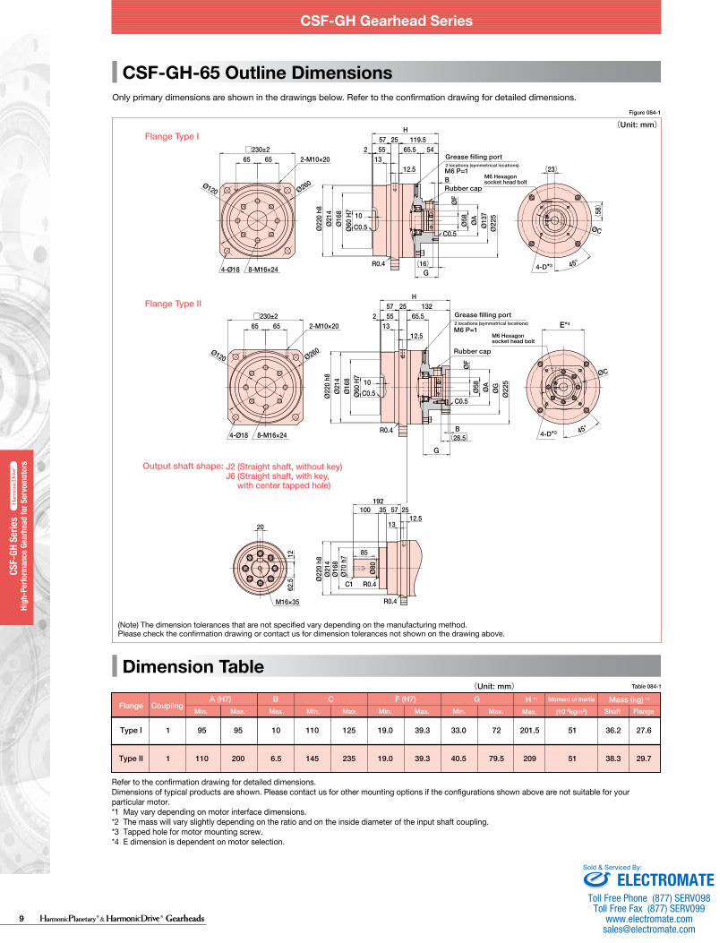
CSF-GH-65 Outline Dimensions
Figure 084-1
(Unit: mm)
Dimension TableTable 083-1(Unit: mm)Table 084-1(Unit: mm)
G
G
Shaft
B
1 95 95 10 110 125 19.0 39.3 33.0 72 36.2 27.6
A (H7) C GF (H7)FlangeMin. Max. Max. Min. Max. Min. Max. Min. Max.
201.5 51
51
Flange
Type I
1 110 200 6.5 145 235 19.0 39.3 40.5 79.5 38.3 29.7209Type II
CouplingMass (kg) *2H *1 Moment of Inertia
Max. (10-4kgm2)
E*4
4-D*3
4-D*3
E*4
4-D*3
4-D*3
Refer to the confirmation drawing for detailed dimensions. Dimensions of typical products are shown. Please contact us for other mounting options if the configurations shown above are not suitable for your particular motor. *1 May vary depending on motor interface dimensions. *2 The mass will vary slightly depending on the ratio and on the inside diameter of the input shaft coupling.*3 Tapped hole for motor mounting screw.*4 E dimension is dependent on motor selection.
Refer to the confirmation drawing for detailed dimensions. Dimensions of typical products are shown. Please contact us for other mounting options if the configurations shown above are not suitable for your particular motor. *1 May vary depending on motor interface dimensions. *2 The mass will vary slightly depending on the ratio and on the inside diameter of the input shaft coupling.*3 Tapped hole for motor mounting screw.*4 E dimension is dependent on motor selection.
056 057
CSF-GH Gearhead Series CSF-GH Gearhead Series
High
-per
form
ance
Gea
r Hea
ds fo
r Ser
vo M
otor
s ser
iesHP
GP se
ries
High
-per
form
ance
Gea
r Hea
ds fo
r Ser
vo M
otor
s ser
iesHP
G se
ries
High
-per
form
ance
Gea
r Hea
ds fo
r Ser
vo M
otor
s ser
iesCS
G-GH
serie
sHi
gh-p
erfo
rman
ce G
ear H
eads
for S
ervo
Mot
ors s
eries
CSF-
GH se
ries
High
-per
form
ance
Gea
r Hea
ds fo
r Ser
vo M
otor
s ser
iesHP
G se
ries (
Orth
ogon
al S
haft
Type
)
High
-per
form
ance
Gea
r Hea
ds fo
r Ser
vo M
otor
s ser
iesHP
GP se
ries
High
-per
form
ance
Gea
r Hea
ds fo
r Ser
vo M
otor
s ser
iesHP
G se
ries
High
-per
form
ance
Gea
r Hea
ds fo
r Ser
vo M
otor
s ser
iesCS
G-GH
serie
sHi
gh-p
erfo
rman
ce G
ear H
eads
for S
ervo
Mot
ors s
eries
CSF-
GH se
ries
High
-per
form
ance
Gea
r Hea
ds fo
r Ser
vo M
otor
s ser
iesHP
G se
ries (
Orth
ogon
al S
haft
Type
)
Flange Type Ⅰ
Flange Type Ⅱ
Output shaft shape: J2 (Straight shaft, without key)J6 (Straight shaft, with key, with center tapped hole)
Flange Type Ⅰ
Flange Type Ⅱ
Output shaft shape: J2 (Straight shaft, without key)J6 (Straight shaft, with key, with center tapped hole)
Rubber cap
Rubber cap
M6 P=1
Grease filling port2 locations (symmetrical locations)
M6 P=1
Grease filling port2 locations (symmetrical locations)
M6 Hexagon socket head bolt
Rubber cap
M6 P=1
Grease filling port2 locations (symmetrical locations)
M6 Hexagon socket head bolt
Rubber cap
M6 P=1
Grease filling port2 locations (symmetrical locations)
M6 Hexagon socket head bolt
M6 Hexagon socket head bolt
Only primary dimensions are shown in the drawings below. Refer to the confirmation drawing for detailed dimensions. Only primary dimensions are shown in the drawings below. Refer to the confirmation drawing for detailed dimensions.
(Note) The dimension tolerances that are not specified vary depending on the manufacturing method. Please check the confirmation drawing or contact us for dimension tolerances not shown on the drawing above.
(Note) The dimension tolerances that are not specified vary depending on the manufacturing method. Please check the confirmation drawing or contact us for dimension tolerances not shown on the drawing above.
G
G
Shaft
B
1 70 110 7 80 150 14.0 29.4 31.5 72 17.3 14.3
A (H7) C GF (H7)FlangeMin. Max. Max. Min. Max. Min. Max. Min. Max.
167
Flange
Type I
2 70 110 7 80 150 19.0 41 40.5 77 17.3 14.3167
1 110 130 6.5 145 200 14.0 29.4 31.5 72 16.7 13.7176
2 110 130 6.5 145 200 19.0 41 40.5 77 17.7 14.7176
Type I
Type II
Type II
Coupling TypicalMass (kg) *2H *1
11
11
11
11
Moment of Inertia
(10-4kgm2)
ELECTROMATEToll Free Phone (877) SERVO98
Toll Free Fax (877) SERV099www.electromate.com
Sold & Serviced By:
9 Gearheads
CSF-GH Gearhead Series
HPG
Serie
sHi
gh-P
erfo
rman
ce G
earh
ead
for S
ervo
mot
ors
HPG
Serie
sHi
gh-P
erfo
rman
ce G
earh
ead
for S
ervo
mot
ors
High
-Per
form
ance
Gea
rhea
d fo
r Ser
vom
otor
s
High
-Per
form
ance
Gea
rhea
d fo
r Ser
vom
otor
s HP
GP S
eries
HPGP
Ser
ies
High
-Per
form
ance
Gea
rhea
d fo
r Ser
vom
otor
s
High
-Per
form
ance
Gea
rhea
d fo
r Ser
vom
otor
s
CSG-
GH S
eries
CSG-
GH S
eries
High
-Per
form
ance
Gea
rhea
d fo
r Ser
vom
otor
s
High
-Per
form
ance
Gea
rhea
d fo
r Ser
vom
otor
s
High
-Per
form
ance
Gea
rhea
d fo
r Ser
vom
otor
s
High
-Per
form
ance
Gea
rhea
d fo
r Ser
vom
otor
s
CSF-
GH S
eries
CSF-
GH S
eries
High
-Per
form
ance
Gea
rhea
d fo
r Ser
vom
otor
s
High
-Per
form
ance
Gea
rhea
d fo
r Ser
vom
otor
s
CSF-
GH S
eries
CSF-
GH S
eries
HPG
Righ
t Ang
le
HPG
Righ
t Ang
le
20
1262
.5
M16×35
C1
Ø80
R0.4
R0.4
85
192100 35 57
13
2512.5
Ø22
0 h8
Ø21
4Ø
168
Ø70
h7
□230±2Ø
220
h8Ø
214
Ø16
8Ø
60 H
7
C0.5
R0.4
10
2 5513
12.5
ØF
Ø58 ØA
ØG
Ø22
5
H57 132
45°
ØC
65.525
65 65
Ø120 Ø260
2-M10×20
8-M16×244-Ø18
C0.5
B(28.5)
□230±265
4-Ø18 8-M16×24
Ø22
0 h8
Ø60
H7
C0.5
R0.4
(58)
(23)
ØC
45°(16)
10
213
12.5B
ØF
C0.5
Ø58
Ø22
5Ø
137
ØA
57 119.5H
255465.555
Ø16
8Ø
214
65
Ø120
2-M10×20
Ø260
14
C1
70
15682 21 53 16
13
R0.4
R0.4
44.5
9
M10×20
Ø50
h7Ø
122
Ø56
Ø16
3Ø
165
h8
□170±2
4-Ø14
16-M8×12
C0.5
253 16 87
H
5113
45 4225
R0.4
C0.5
(28.5)
10
Ø16
5 h8
Ø16
3Ø
122
Ø47
H7
Ø190
Ø100
B
ØF
Ø58 ØA
Ø16
5 ØC
45°
□170±2
4-Ø14
Ø16
5 h8
Ø16
3Ø
122
Ø47
H7
C0.5
R0.4
10
2135153 16 98
H
58
ØF
Ø50 ØA
Ø16
7B
C0.5
(14.5)
(62)
45°
ØC
Ø100
Ø190
16-M8×12
CSF-GH-45 Outline Dimensions
Dimension Table
Figure 083-1
(Unit: mm)
CSF-GH-65 Outline Dimensions
Figure 084-1
(Unit: mm)
Dimension TableTable 083-1(Unit: mm)Table 084-1(Unit: mm)
G
G
Shaft
B
1 95 95 10 110 125 19.0 39.3 33.0 72 36.2 27.6
A (H7) C GF (H7)FlangeMin. Max. Max. Min. Max. Min. Max. Min. Max.
201.5 51
51
Flange
Type I
1 110 200 6.5 145 235 19.0 39.3 40.5 79.5 38.3 29.7209Type II
CouplingMass (kg) *2H *1 Moment of Inertia
Max. (10-4kgm2)
E*4
4-D*3
4-D*3
E*4
4-D*3
4-D*3
Refer to the confirmation drawing for detailed dimensions. Dimensions of typical products are shown. Please contact us for other mounting options if the configurations shown above are not suitable for your particular motor. *1 May vary depending on motor interface dimensions. *2 The mass will vary slightly depending on the ratio and on the inside diameter of the input shaft coupling.*3 Tapped hole for motor mounting screw.*4 E dimension is dependent on motor selection.
Refer to the confirmation drawing for detailed dimensions. Dimensions of typical products are shown. Please contact us for other mounting options if the configurations shown above are not suitable for your particular motor. *1 May vary depending on motor interface dimensions. *2 The mass will vary slightly depending on the ratio and on the inside diameter of the input shaft coupling.*3 Tapped hole for motor mounting screw.*4 E dimension is dependent on motor selection.
056 057
CSF-GH Gearhead Series CSF-GH Gearhead Series
High
-per
form
ance
Gea
r Hea
ds fo
r Ser
vo M
otor
s ser
iesHP
GP se
ries
High
-per
form
ance
Gea
r Hea
ds fo
r Ser
vo M
otor
s ser
iesHP
G se
ries
High
-per
form
ance
Gea
r Hea
ds fo
r Ser
vo M
otor
s ser
iesCS
G-GH
serie
sHi
gh-p
erfo
rman
ce G
ear H
eads
for S
ervo
Mot
ors s
eries
CSF-
GH se
ries
High
-per
form
ance
Gea
r Hea
ds fo
r Ser
vo M
otor
s ser
iesHP
G se
ries (
Orth
ogon
al S
haft
Type
)
High
-per
form
ance
Gea
r Hea
ds fo
r Ser
vo M
otor
s ser
iesHP
GP se
ries
High
-per
form
ance
Gea
r Hea
ds fo
r Ser
vo M
otor
s ser
iesHP
G se
ries
High
-per
form
ance
Gea
r Hea
ds fo
r Ser
vo M
otor
s ser
iesCS
G-GH
serie
sHi
gh-p
erfo
rman
ce G
ear H
eads
for S
ervo
Mot
ors s
eries
CSF-
GH se
ries
High
-per
form
ance
Gea
r Hea
ds fo
r Ser
vo M
otor
s ser
iesHP
G se
ries (
Orth
ogon
al S
haft
Type
)
Flange Type Ⅰ
Flange Type Ⅱ
Output shaft shape: J2 (Straight shaft, without key)J6 (Straight shaft, with key, with center tapped hole)
Flange Type Ⅰ
Flange Type Ⅱ
Output shaft shape: J2 (Straight shaft, without key)J6 (Straight shaft, with key, with center tapped hole)
Rubber cap
Rubber cap
M6 P=1
Grease filling port2 locations (symmetrical locations)
M6 P=1
Grease filling port2 locations (symmetrical locations)
M6 Hexagon socket head bolt
Rubber cap
M6 P=1
Grease filling port2 locations (symmetrical locations)
M6 Hexagon socket head bolt
Rubber cap
M6 P=1
Grease filling port2 locations (symmetrical locations)
M6 Hexagon socket head bolt
M6 Hexagon socket head bolt
Only primary dimensions are shown in the drawings below. Refer to the confirmation drawing for detailed dimensions. Only primary dimensions are shown in the drawings below. Refer to the confirmation drawing for detailed dimensions.
(Note) The dimension tolerances that are not specified vary depending on the manufacturing method. Please check the confirmation drawing or contact us for dimension tolerances not shown on the drawing above.
(Note) The dimension tolerances that are not specified vary depending on the manufacturing method. Please check the confirmation drawing or contact us for dimension tolerances not shown on the drawing above.
G
G
Shaft
B
1 70 110 7 80 150 14.0 29.4 31.5 72 17.3 14.3
A (H7) C GF (H7)FlangeMin. Max. Max. Min. Max. Min. Max. Min. Max.
167
Flange
Type I
2 70 110 7 80 150 19.0 41 40.5 77 17.3 14.3167
1 110 130 6.5 145 200 14.0 29.4 31.5 72 16.7 13.7176
2 110 130 6.5 145 200 19.0 41 40.5 77 17.7 14.7176
Type I
Type II
Type II
Coupling TypicalMass (kg) *2H *1
11
11
11
11
Moment of Inertia
(10-4kgm2)
ELECTROMATEToll Free Phone (877) SERVO98
Toll Free Fax (877) SERV099www.electromate.com
Sold & Serviced By:

10Gearheads
CSF-GH Gearhead Series
HPG
Serie
sHi
gh-P
erfo
rman
ce G
earh
ead
for S
ervo
mot
ors
HPG
Serie
sHi
gh-P
erfo
rman
ce G
earh
ead
for S
ervo
mot
ors
High
-Per
form
ance
Gea
rhea
d fo
r Ser
vom
otor
s
High
-Per
form
ance
Gea
rhea
d fo
r Ser
vom
otor
s HP
GP S
eries
HPGP
Ser
ies
High
-Per
form
ance
Gea
rhea
d fo
r Ser
vom
otor
s
High
-Per
form
ance
Gea
rhea
d fo
r Ser
vom
otor
s
CSG-
GH S
eries
CSG-
GH S
eries
High
-Per
form
ance
Gea
rhea
d fo
r Ser
vom
otor
s
High
-Per
form
ance
Gea
rhea
d fo
r Ser
vom
otor
s
High
-Per
form
ance
Gea
rhea
d fo
r Ser
vom
otor
s
High
-Per
form
ance
Gea
rhea
d fo
r Ser
vom
otor
s
CSF-
GH S
eries
CSF-
GH S
eries
High
-Per
form
ance
Gea
rhea
d fo
r Ser
vom
otor
s
High
-Per
form
ance
Gea
rhea
d fo
r Ser
vom
otor
s
CSF-
GH S
eries
CSF-
GH S
eries
HPG
Righ
t Ang
le
HPG
Righ
t Ang
le
■NOTES
NOTES
0° 90° 180° 360°
Wave GeneratorThe Wave Generator is a thin raced ball bearing fitted onto an elliptical hub. This serves as a high efficiency torque converter and is generally mounted onto the input or motor shaft.
FlexsplineThe Flexspline is a non-rigid, thin cylindrical cup with external teeth on the open end of the cup. The Flexspline fits over the Wave Generator and takes on its elliptical shape. The Flexspline is generally used as the output of the gear.
Circular SplineThe Circular Spline is a rigid ring with internal teeth. It engages the teeth of the Flexspline across the major axis of the Wave Generator ellipse. The Circular Spline has two more teeth than the Flexspline and is generally mounted onto a housing.
Circular Spline
Wave Generator
Flexspline
The Flexspline is slightly smaller in diameter than the Circular Spline and usually has two fewer teeth than the Circular Spline. The elliptical shape of the Wave Generator causes the teeth of the Flexspline to engage the Circular Spline at two opposite regions across the major axis of the ellipse.
As the Wave Generator rotates the teeth of the Flexspline engage with the Circular Spline at the major axis.
For every 180 degree clockwise movement of the Wave Generator the Flexspline rotates counterclockwise by one tooth in relation to the Circular Spline.
Each complete clockwise rotation of the Wave Generator results in the Flexspline moving counter-clockwise by two teeth from its original position relative to the Circular Spline. Normally, this motion is taken out as output.
Direction of RotationThe output rotational direction of CSG/CSF-GH series is reverse of the input rotational direction.Input: Wave Generator (Motor shaft mounting)Fixed: Circular Spline (Casing)Output: Flexspline (Cross roller bearing)
Circular Spline
Flexspline
The Harmonic Drive® gear utilizes a unique gear tooth profile for optimized tooth engagement. Unlike an involute tooth profile, this tooth profile (“S tooth”) enables about 30% of the total number of teeth to be engaged simultaneously. This technological innovation results in high torque, high torsional stiffness, long life and smooth rotation.
Tooth behavior and engagement
Operating Principles
Operating Principle Gearheads
™
A simple three element construction combined with the unique operating principle puts extremely high reduction ratio capabilities into a very compact and lightweight package. The high performance attributes of this gearing technology including zero backlash, high torque, compact size, and excellent positional accuracy are a direct result of the unique operating principles.
ELECTROMATEToll Free Phone (877) SERVO98
Toll Free Fax (877) SERV099www.electromate.com
Sold & Serviced By:

11 Gearheads
CSG-GH/CSF-GH Gearhead Series
HPG
Serie
sHi
gh-P
erfo
rman
ce G
earh
ead
for S
ervo
mot
ors
HPG
Serie
sHi
gh-P
erfo
rman
ce G
earh
ead
for S
ervo
mot
ors
High
-Per
form
ance
Gea
rhea
d fo
r Ser
vom
otor
s
High
-Per
form
ance
Gea
rhea
d fo
r Ser
vom
otor
s HP
GP S
eries
HPGP
Ser
ies
High
-Per
form
ance
Gea
rhea
d fo
r Ser
vom
otor
s
High
-Per
form
ance
Gea
rhea
d fo
r Ser
vom
otor
s
CSG-
GH S
eries
CSG-
GH S
eries
High
-Per
form
ance
Gea
rhea
d fo
r Ser
vom
otor
s
High
-Per
form
ance
Gea
rhea
d fo
r Ser
vom
otor
s
High
-Per
form
ance
Gea
rhea
d fo
r Ser
vom
otor
s
High
-Per
form
ance
Gea
rhea
d fo
r Ser
vom
otor
s
CSF-
GH S
eries
CSF-
GH S
eries
High
-Per
form
ance
Gea
rhea
d fo
r Ser
vom
otor
s
High
-Per
form
ance
Gea
rhea
d fo
r Ser
vom
otor
s
CSF-
GH S
eries
CSF-
GH S
eries
HPG
Righ
t Ang
le
HPG
Righ
t Ang
le
Torque Limits
Life
+
ー+
ー
Graph 086-1
Life
Calculation formula for Rated Lifetime
Lh=Ln ・ ・ TavTr 3
NavNr
Formula 086-1
Table 086-1
Table 086-2
LnTrNr
TavNav
105 106 107 108 109 1010
0
1
2
3
4
5
6
7
8
9
10
16
17
Graph 086-2
Formula 087-1
Figure 087-1
N= 1.0×10⁴
2× ×tn60
Caution
N occurancest secn rpm
Permissible occurancesTime that impact torque is appliedRotational speed of the wave generator
The flexspline bends two times per one revolution of the wave generator.
If the number of occurances is exceeded, the Flexspline may experience a fatigue failure.
Calculation formula
Warning
When the flexspline buckles, early failure of the HarmonicDrive® gear may occur.
When a highly excessive torque (16 to 17 times rated torque) is applied to the output with the input stationary, the flexspline may experience plastic deformation. This is defined as buckling torque.
■ Buckling torque
* See the corresponding pages of each series for buckling torque values.
CSG-GH/CSF-GH Gearhead Series CSG-GH/CSF-GH Gearhead Series
036 037
High
-per
form
ance
Gea
r Hea
ds fo
r Ser
vo M
otor
s ser
iesHP
GP se
ries
High
-per
form
ance
Gea
r Hea
ds fo
r Ser
vo M
otor
s ser
iesHP
G se
ries
High
-per
form
ance
Gea
r Hea
ds fo
r Ser
vo M
otor
s ser
iesCS
G-GH
serie
sHi
gh-p
erfo
rman
ce G
ear H
eads
for S
ervo
Mot
ors s
eries
CSF-
GH se
ries
High
-per
form
ance
Gea
r Hea
ds fo
r Ser
vo M
otor
s ser
iesHP
G se
ries (
Orth
ogon
al S
haft
Type
)
High
-per
form
ance
Gea
r Hea
ds fo
r Ser
vo M
otor
s ser
iesHP
GP se
ries
High
-per
form
ance
Gea
r Hea
ds fo
r Ser
vo M
otor
s ser
iesHP
G se
ries
High
-per
form
ance
Gea
r Hea
ds fo
r Ser
vo M
otor
s ser
iesCS
G-GH
serie
sHi
gh-p
erfo
rman
ce G
ear H
eads
for S
ervo
Mot
ors s
eries
CSF-
GH se
ries
High
-per
form
ance
Gea
r Hea
ds fo
r Ser
vo M
otor
s ser
iesHP
G se
ries (
Orth
ogon
al S
haft
Type
)
Rating Table Definitions
See the corresponding pages of each series for values from the ratings.
Example of load torque pattern
Start
(Speed cycle)
Load
torq
ue
Start
Stop
Steady
Time
Time
Wav
e G
ener
ator
rota
tiona
l spe
ed Max
. mom
enta
ry to
rque
Torq
ue a
t ste
ady
stat
e
Peak
torq
ue a
t sta
rt/st
op
Abnormal impact torque
■ Rated torqueRated torque indicates allowable continuous load torque at input speed.
■ Inertia The rating indicates the moment of inertia reflected to the gear input.
■ Maximum Average Input Speed Maximum Input Speed Do not exceed the allowable rating. (calculation formula of the average input speed: Page 91).
■ Limit for Repeated Peak Torque (see Graph 086-1)
During acceleration and deceleration the Harmonic Drive® gear experiences a peak torque as a result of the moment of inertia of the output load. The table indicates the limit for repeated peak torque.
■ Limit for Momentary Torque (see Graph 086-1)
The gear may be subjected to momentary peak torques in the event of a collision or emergency stop. The magnitude and frequency of occurrence of such peak torques must be kept to a minimum and they should, under no circumstance, occur during normal operating cycle. The allowable number of occurrences of the momentary peak torque may be calculated by using formula 073-1.
■ Limit for Average TorqueIn cases where load torque and input speed vary, it is necessary to calculate an average value of load torque. The table indicates the limit for average torque. The average torque calculated must not exceed this limit. (calculation formula: Page 91)
■ Life of the wave generatorThe life of a gear is determined by the life of the wavegenerator bearing. The life may be calculated by using theinput speed and the output load torque.
CSF-GH
7,000 hours35,000 hours
CSG-GH
10,000 hours50,000 hours
Series name
L10 L50 (average life)
Life of L10 or L50c Rated torqueRated input speedAverage load torque on the output side (calculation formula: Page 91)Average input speed (calculation formula: Page 91)
* Life is based on the input speed and output load torque from the ratings.
Buckling torque
Racheting torque
Fatigue strength of the flexspline
Repeated peak torque
Rated torque
Life of wave generator (L10)
Momentary peak torque
Load
torq
ue (w
hen
the
rate
d to
rque
is 1
)
Relative torque rating
Total number of input rotations
* Lubricant life not taken into consideration in the graph described above.* Use the graph above as reference values.
The Flexspline is subjected to repeated deflections, and its strength determines the torque capacity of the Harmonic Drive® gear. The values given for Rated Torque at Rated Speed and for the allowable Repeated Peak Torque are based on an infinite fatiguelife for the Flexspline. The torque that occurs during a collision must be below the momentary peak torque (impact torque). The maximum number of occurrences is given by the equation below.
■ Strength of flexspline
Allowable limit of the bending cycles of the flexspline during rotation of the wave generator while the impact torque is applied: 1.0 x 10⁴ (cycles)
The torque that occurs during a collision must be below the momentary peak torque (impact torque). The maximum numberof occurrences is given by the equation below.
When excessive torque (8 to 9 times rated torque) is applied while the gear is in motion, the teeth between the Circular Spline and Flexspline may not engage properly.This phenomenon is called ratcheting and the torque at whichthis occurs is called ratcheting torque. Ratcheting may cause theFlexspline to become non-concentric with the Circular Spline. Operating in this condition may result in shortened life and a Flexspline fatigue failure. * See the corresponding pages of each series for ratcheting torque values.* Ratcheting torque is affected by the stiffness of the housing to be used when
installing the circular spline. Contact us for details of the ratcheting torque.
■ Ratcheting torque
Caution
Caution
When ratcheting occurs, the teeth may not be correctly engaged and become out of alignment as shown in Figure 087-1. Operating the drive in this condition will cause vibration and damage the flexspline.
Once ratcheting occurs, the teeth wear excessively and the ratcheting torque may be lowered.
Circular Spline
"Dedoidal" condition.
Flexspline
ELECTROMATEToll Free Phone (877) SERVO98
Toll Free Fax (877) SERV099www.electromate.com
Sold & Serviced By:

12Gearheads
CSG-GH/CSF-GH Gearhead Series
HPG
Serie
sHi
gh-P
erfo
rman
ce G
earh
ead
for S
ervo
mot
ors
HPG
Serie
sHi
gh-P
erfo
rman
ce G
earh
ead
for S
ervo
mot
ors
High
-Per
form
ance
Gea
rhea
d fo
r Ser
vom
otor
s
High
-Per
form
ance
Gea
rhea
d fo
r Ser
vom
otor
s HP
GP S
eries
HPGP
Ser
ies
High
-Per
form
ance
Gea
rhea
d fo
r Ser
vom
otor
s
High
-Per
form
ance
Gea
rhea
d fo
r Ser
vom
otor
s
CSG-
GH S
eries
CSG-
GH S
eries
High
-Per
form
ance
Gea
rhea
d fo
r Ser
vom
otor
s
High
-Per
form
ance
Gea
rhea
d fo
r Ser
vom
otor
s
High
-Per
form
ance
Gea
rhea
d fo
r Ser
vom
otor
s
High
-Per
form
ance
Gea
rhea
d fo
r Ser
vom
otor
s
CSF-
GH S
eries
CSF-
GH S
eries
High
-Per
form
ance
Gea
rhea
d fo
r Ser
vom
otor
s
High
-Per
form
ance
Gea
rhea
d fo
r Ser
vom
otor
s
CSF-
GH S
eries
CSF-
GH S
eries
HPG
Righ
t Ang
le
HPG
Righ
t Ang
le
Torque Limits
Life
+
ー
+
ー
Graph 086-1
Life
Calculation formula for Rated Lifetime
Lh=Ln ・ ・ TavTr 3
NavNr
Formula 086-1
Table 086-1
Table 086-2
LnTrNr
TavNav
105 106 107 108 109 1010
0
1
2
3
4
5
6
7
8
9
10
16
17
Graph 086-2
Formula 087-1
Figure 087-1
N= 1.0×10⁴
2× ×tn60
Caution
N occurancest secn rpm
Permissible occurancesTime that impact torque is appliedRotational speed of the wave generator
The flexspline bends two times per one revolution of the wave generator.
If the number of occurances is exceeded, the Flexspline may experience a fatigue failure.
Calculation formula
Warning
When the flexspline buckles, early failure of the HarmonicDrive® gear may occur.
When a highly excessive torque (16 to 17 times rated torque) is applied to the output with the input stationary, the flexspline may experience plastic deformation. This is defined as buckling torque.
■ Buckling torque
* See the corresponding pages of each series for buckling torque values.
CSG-GH/CSF-GH Gearhead Series CSG-GH/CSF-GH Gearhead Series
036 037
High
-per
form
ance
Gea
r Hea
ds fo
r Ser
vo M
otor
s ser
iesHP
GP se
ries
High
-per
form
ance
Gea
r Hea
ds fo
r Ser
vo M
otor
s ser
iesHP
G se
ries
High
-per
form
ance
Gea
r Hea
ds fo
r Ser
vo M
otor
s ser
iesCS
G-GH
serie
sHi
gh-p
erfo
rman
ce G
ear H
eads
for S
ervo
Mot
ors s
eries
CSF-
GH se
ries
High
-per
form
ance
Gea
r Hea
ds fo
r Ser
vo M
otor
s ser
iesHP
G se
ries (
Orth
ogon
al S
haft
Type
)
High
-per
form
ance
Gea
r Hea
ds fo
r Ser
vo M
otor
s ser
iesHP
GP se
ries
High
-per
form
ance
Gea
r Hea
ds fo
r Ser
vo M
otor
s ser
iesHP
G se
ries
High
-per
form
ance
Gea
r Hea
ds fo
r Ser
vo M
otor
s ser
iesCS
G-GH
serie
sHi
gh-p
erfo
rman
ce G
ear H
eads
for S
ervo
Mot
ors s
eries
CSF-
GH se
ries
High
-per
form
ance
Gea
r Hea
ds fo
r Ser
vo M
otor
s ser
iesHP
G se
ries (
Orth
ogon
al S
haft
Type
)
Rating Table Definitions
See the corresponding pages of each series for values from the ratings.
Example of load torque pattern
Start
(Speed cycle)
Load
torq
ue
Start
Stop
Steady
Time
Time
Wav
e G
ener
ator
rota
tiona
l spe
ed Max
. mom
enta
ry to
rque
Torq
ue a
t ste
ady
stat
e
Peak
torq
ue a
t sta
rt/st
op
Abnormal impact torque
■ Rated torqueRated torque indicates allowable continuous load torque at input speed.
■ Inertia The rating indicates the moment of inertia reflected to the gear input.
■ Maximum Average Input Speed Maximum Input Speed Do not exceed the allowable rating. (calculation formula of the average input speed: Page 91).
■ Limit for Repeated Peak Torque (see Graph 086-1)
During acceleration and deceleration the Harmonic Drive® gear experiences a peak torque as a result of the moment of inertia of the output load. The table indicates the limit for repeated peak torque.
■ Limit for Momentary Torque (see Graph 086-1)
The gear may be subjected to momentary peak torques in the event of a collision or emergency stop. The magnitude and frequency of occurrence of such peak torques must be kept to a minimum and they should, under no circumstance, occur during normal operating cycle. The allowable number of occurrences of the momentary peak torque may be calculated by using formula 073-1.
■ Limit for Average TorqueIn cases where load torque and input speed vary, it is necessary to calculate an average value of load torque. The table indicates the limit for average torque. The average torque calculated must not exceed this limit. (calculation formula: Page 91)
■ Life of the wave generatorThe life of a gear is determined by the life of the wavegenerator bearing. The life may be calculated by using theinput speed and the output load torque.
CSF-GH
7,000 hours35,000 hours
CSG-GH
10,000 hours50,000 hours
Series name
L10 L50 (average life)
Life of L10 or L50c Rated torqueRated input speedAverage load torque on the output side (calculation formula: Page 91)Average input speed (calculation formula: Page 91)
* Life is based on the input speed and output load torque from the ratings.
Buckling torque
Racheting torque
Fatigue strength of the flexspline
Repeated peak torque
Rated torque
Life of wave generator (L10)
Momentary peak torque
Load
torq
ue (w
hen
the
rate
d to
rque
is 1
)
Relative torque rating
Total number of input rotations
* Lubricant life not taken into consideration in the graph described above.* Use the graph above as reference values.
The Flexspline is subjected to repeated deflections, and its strength determines the torque capacity of the Harmonic Drive® gear. The values given for Rated Torque at Rated Speed and for the allowable Repeated Peak Torque are based on an infinite fatiguelife for the Flexspline. The torque that occurs during a collision must be below the momentary peak torque (impact torque). The maximum number of occurrences is given by the equation below.
■ Strength of flexspline
Allowable limit of the bending cycles of the flexspline during rotation of the wave generator while the impact torque is applied: 1.0 x 10⁴ (cycles)
The torque that occurs during a collision must be below the momentary peak torque (impact torque). The maximum numberof occurrences is given by the equation below.
When excessive torque (8 to 9 times rated torque) is applied while the gear is in motion, the teeth between the Circular Spline and Flexspline may not engage properly.This phenomenon is called ratcheting and the torque at whichthis occurs is called ratcheting torque. Ratcheting may cause theFlexspline to become non-concentric with the Circular Spline. Operating in this condition may result in shortened life and a Flexspline fatigue failure. * See the corresponding pages of each series for ratcheting torque values.* Ratcheting torque is affected by the stiffness of the housing to be used when
installing the circular spline. Contact us for details of the ratcheting torque.
■ Ratcheting torque
Caution
Caution
When ratcheting occurs, the teeth may not be correctly engaged and become out of alignment as shown in Figure 087-1. Operating the drive in this condition will cause vibration and damage the flexspline.
Once ratcheting occurs, the teeth wear excessively and the ratcheting torque may be lowered.
Circular Spline
"Dedoidal" condition.
Flexspline
ELECTROMATEToll Free Phone (877) SERVO98
Toll Free Fax (877) SERV099www.electromate.com
Sold & Serviced By:

13 Gearheads
CSG-GH/CSF-GH Gearhead Series
HPG
Serie
sHi
gh-P
erfo
rman
ce G
earh
ead
for S
ervo
mot
ors
HPG
Serie
sHi
gh-P
erfo
rman
ce G
earh
ead
for S
ervo
mot
ors
High
-Per
form
ance
Gea
rhea
d fo
r Ser
vom
otor
s
High
-Per
form
ance
Gea
rhea
d fo
r Ser
vom
otor
s HP
GP S
eries
HPGP
Ser
ies
High
-Per
form
ance
Gea
rhea
d fo
r Ser
vom
otor
s
High
-Per
form
ance
Gea
rhea
d fo
r Ser
vom
otor
s
CSG-
GH S
eries
CSG-
GH S
eries
High
-Per
form
ance
Gea
rhea
d fo
r Ser
vom
otor
s
High
-Per
form
ance
Gea
rhea
d fo
r Ser
vom
otor
s
High
-Per
form
ance
Gea
rhea
d fo
r Ser
vom
otor
s
High
-Per
form
ance
Gea
rhea
d fo
r Ser
vom
otor
s
CSF-
GH S
eries
CSF-
GH S
eries
High
-Per
form
ance
Gea
rhea
d fo
r Ser
vom
otor
s
High
-Per
form
ance
Gea
rhea
d fo
r Ser
vom
otor
s
CSF-
GH S
eries
CSF-
GH S
eries
HPG
Righ
t Ang
le
HPG
Righ
t Ang
le
Torsional Stiffness Vibration
Efficiency
θ 1 K 1
T 1 T 2
θ 2
K 2
K 3
0
−T 0 +T 00
A
A'
B
B'
Figure 088-1
Figure 088-2
Stiffness and backlash of the drive system greatly affects the performance of the servo system. Please perform a detailed review of these items before designing your equipment and selecting a model number.
Fixing the input side (wave generator) and applying torque to the output side (flexspline) generates torsion almost proportional to the torque on the output side. Figure 088-1 shows the torsional angle at the output side when the torque applied on the output side starts from zero, increases up to +T0 and decreases down to –T0. This is called the “Torque – torsion angle diagram,” which normally draws a loop of 0 – A – B – Aʼ – Bʼ – A. The slope described in the “Torque – torsion angle diagram” is represented as the spring constant for the stiffness of the HarmonicDrive® gear (unit: Nm/rad).As shown in Figure 074-2, this “Torque – torsional angle diagram” is divided into 3 regions, and the spring constants in the area are represented by K1, K2 and K3.
■ Stiffness
■ See the corresponding pages of each series for values of the spring constants (K1, K2, K3) and the torque-torsional angles (T1, T2, - θ1, θ2).
K1 ···· The spring constant when the torque changes from [zero] to [T1]K2 ···· The spring constant when the torque changes from [T1] to [T2]K3 ···· The spring constant when the torque changes from [T2] to [T3]
■ Hysteresis loss
■ See the appropriate page for each model series for the hysteresis loss value.
As shown in Figure 088-1, when the applied torque is increased to the rated torque and is brought back to [zero], the torsional angle does not return exactly back to the zero point This small difference (B – B') is called hysteresis loss.
Table 089-1
Formula 089-2
Formula 089-1
N = −−− ・ 60 = 450 rpm2
15
12π
KJ
f =
f Hz
KJ
Nm/radkgm2
■ BacklashHysteresis loss is primarily caused by internal friction. It is a very small value and will vary roughly in proportion to the applied load. Because HarmonicDrive® gearheads have zero backlash, the only true backlash is due to the clearance in the Oldham coupling, a self-aligning mechanism used on the wave generator. Since the Oldham coupling is used on the input, the backlash measured at the output is extremely small (arc-seconds) since it is divided by the gear reduction ratio.
The efficiency will vary depending on the following factors:■ Reduction ratio■ Input speed■ Load torque■ Temperature■ Lubrication condition (Type of lubricant and the quantity)
CSG-GH/CSF-GH Gearhead Series CSG-GH/CSF-GH Gearhead Series
038 039
High
-per
form
ance
Gea
r Hea
ds fo
r Ser
vo M
otor
s ser
iesHP
GP se
ries
High
-per
form
ance
Gea
r Hea
ds fo
r Ser
vo M
otor
s ser
iesHP
G se
ries
High
-per
form
ance
Gea
r Hea
ds fo
r Ser
vo M
otor
s ser
iesCS
G-GH
serie
sHi
gh-p
erfo
rman
ce G
ear H
eads
for S
ervo
Mot
ors s
eries
CSF-
GH se
ries
High
-per
form
ance
Gea
r Hea
ds fo
r Ser
vo M
otor
s ser
iesHP
G se
ries (
Orth
ogon
al S
haft
Type
)
High
-per
form
ance
Gea
r Hea
ds fo
r Ser
vo M
otor
s ser
iesHP
GP se
ries
High
-per
form
ance
Gea
r Hea
ds fo
r Ser
vo M
otor
s ser
iesHP
G se
ries
High
-per
form
ance
Gea
r Hea
ds fo
r Ser
vo M
otor
s ser
iesCS
G-GH
serie
sHi
gh-p
erfo
rman
ce G
ear H
eads
for S
ervo
Mot
ors s
eries
CSF-
GH se
ries
High
-per
form
ance
Gea
r Hea
ds fo
r Ser
vo M
otor
s ser
iesHP
G se
ries (
Orth
ogon
al S
haft
Type
)
■ Example for calculating the torsion angleThe torsion angle (θ) is calculated here using CSG-32-100-GH as an example. T1 = 29 Nm T2 = 108 Nm K1 = 6.7 x 10⁴ Nm/rad K2 = 6.7 x 10⁴ Nm/rad K3 = 6.7 x 10⁴ Nm/rad θ1=4.4 x 10⁻⁴ rad θ2=11.6 x 10⁻⁴ rad When the applied torque is T1 or less, the torsion angle θL1 is calculated as follows: When the load torque TL1=6.0 Nm θL1 =TL1/K1 =6.0/6.7×104 =9.0×10⁻⁵ rad(0.31 arc min) When the applied torque is between T1 and T2, the torsion angle θL2 is calculated as follows: When the load torque is TL2=50 Nm θL2 =θ1+(TL2−T1)/K2 =4.4×10⁻⁴ +(50−6)/11.0×104 =4.4×10⁻⁴ +40.0×10-5 =8.4×10⁻⁴ rad(2.89 arc min) When the applied torque is greater than T2, the torsion angle θL3 is calculated as follows: When the load torque is TL3=178 Nm θL3 =θ1+θ2+(TL3−T2)/K3 =4.4×10⁻⁴ +11.6×10⁻⁴+(178−108)/12.0×104 =4.4×10⁻⁴ +11.6×10⁻⁴+5.8×10-4 =2.18×10⁻³ rad(7.5 arc min) When a bidirectional load is applied, the total torsion angle will be 2 x θLX plus hysteresis loss.
* The torsion angle calculation is for the gear component set only and does not include any torsional windup of the output shaft.
Torque - torsion angle diagramTorsion angle
Hysteresis loss
Torque
Spring constant diagramTorsion angle
Torque
The primary frequency of the transmission error of the HarmonicDrive® gear may rarely cause a vibration of the load inertia. This can occur when the driving frequency of the servo system including the HarmonicDrive® gear is at, or close to the resonant frequency of the system. Refer to the design guide of each series.
The primary component of the transmission error occurs twice per input revolution of the input. Therefore, the frequency generated by the transmission error is 2x the input frequency (rev / sec).
If the resonant frequency of the entire system, including the HarmonicDrive® gear, is F=15 Hz, then the input speed (N) which would generate that frequency could be calculated with the formula below.
The resonant frequency is generated at an input speed of 450 rpm.
How to the calculate resonant frequency of the system
Formula variablesThe resonant frequency of the system
Spring constant of the HarmonicDrive® gearLoad inertia
See pages of each series.
ELECTROMATEToll Free Phone (877) SERVO98
Toll Free Fax (877) SERV099www.electromate.com
Sold & Serviced By:

14Gearheads
CSG-GH/CSF-GH Gearhead Series
HPG
Serie
sHi
gh-P
erfo
rman
ce G
earh
ead
for S
ervo
mot
ors
HPG
Serie
sHi
gh-P
erfo
rman
ce G
earh
ead
for S
ervo
mot
ors
High
-Per
form
ance
Gea
rhea
d fo
r Ser
vom
otor
s
High
-Per
form
ance
Gea
rhea
d fo
r Ser
vom
otor
s HP
GP S
eries
HPGP
Ser
ies
High
-Per
form
ance
Gea
rhea
d fo
r Ser
vom
otor
s
High
-Per
form
ance
Gea
rhea
d fo
r Ser
vom
otor
s
CSG-
GH S
eries
CSG-
GH S
eries
High
-Per
form
ance
Gea
rhea
d fo
r Ser
vom
otor
s
High
-Per
form
ance
Gea
rhea
d fo
r Ser
vom
otor
s
High
-Per
form
ance
Gea
rhea
d fo
r Ser
vom
otor
s
High
-Per
form
ance
Gea
rhea
d fo
r Ser
vom
otor
s
CSF-
GH S
eries
CSF-
GH S
eries
High
-Per
form
ance
Gea
rhea
d fo
r Ser
vom
otor
s
High
-Per
form
ance
Gea
rhea
d fo
r Ser
vom
otor
s
CSF-
GH S
eries
CSF-
GH S
eries
HPG
Righ
t Ang
le
HPG
Righ
t Ang
le
Torsional Stiffness Vibration
Efficiency
θ 1 K 1
T 1 T 2
θ 2
K 2
K 3
0
−T 0 +T 00
A
A'
B
B'
Figure 088-1
Figure 088-2
Stiffness and backlash of the drive system greatly affects the performance of the servo system. Please perform a detailed review of these items before designing your equipment and selecting a model number.
Fixing the input side (wave generator) and applying torque to the output side (flexspline) generates torsion almost proportional to the torque on the output side. Figure 088-1 shows the torsional angle at the output side when the torque applied on the output side starts from zero, increases up to +T0 and decreases down to –T0. This is called the “Torque – torsion angle diagram,” which normally draws a loop of 0 – A – B – Aʼ – Bʼ – A. The slope described in the “Torque – torsion angle diagram” is represented as the spring constant for the stiffness of the HarmonicDrive® gear (unit: Nm/rad).As shown in Figure 074-2, this “Torque – torsional angle diagram” is divided into 3 regions, and the spring constants in the area are represented by K1, K2 and K3.
■ Stiffness
■ See the corresponding pages of each series for values of the spring constants (K1, K2, K3) and the torque-torsional angles (T1, T2, - θ1, θ2).
K1 ···· The spring constant when the torque changes from [zero] to [T1]K2 ···· The spring constant when the torque changes from [T1] to [T2]K3 ···· The spring constant when the torque changes from [T2] to [T3]
■ Hysteresis loss
■ See the appropriate page for each model series for the hysteresis loss value.
As shown in Figure 088-1, when the applied torque is increased to the rated torque and is brought back to [zero], the torsional angle does not return exactly back to the zero point This small difference (B – B') is called hysteresis loss.
Table 089-1
Formula 089-2
Formula 089-1
N = −−− ・ 60 = 450 rpm2
15
12π
KJ
f =
f Hz
KJ
Nm/radkgm2
■ BacklashHysteresis loss is primarily caused by internal friction. It is a very small value and will vary roughly in proportion to the applied load. Because HarmonicDrive® gearheads have zero backlash, the only true backlash is due to the clearance in the Oldham coupling, a self-aligning mechanism used on the wave generator. Since the Oldham coupling is used on the input, the backlash measured at the output is extremely small (arc-seconds) since it is divided by the gear reduction ratio.
The efficiency will vary depending on the following factors:■ Reduction ratio■ Input speed■ Load torque■ Temperature■ Lubrication condition (Type of lubricant and the quantity)
CSG-GH/CSF-GH Gearhead Series CSG-GH/CSF-GH Gearhead Series
038 039
High
-per
form
ance
Gea
r Hea
ds fo
r Ser
vo M
otor
s ser
iesHP
GP se
ries
High
-per
form
ance
Gea
r Hea
ds fo
r Ser
vo M
otor
s ser
iesHP
G se
ries
High
-per
form
ance
Gea
r Hea
ds fo
r Ser
vo M
otor
s ser
iesCS
G-GH
serie
sHi
gh-p
erfo
rman
ce G
ear H
eads
for S
ervo
Mot
ors s
eries
CSF-
GH se
ries
High
-per
form
ance
Gea
r Hea
ds fo
r Ser
vo M
otor
s ser
iesHP
G se
ries (
Orth
ogon
al S
haft
Type
)
High
-per
form
ance
Gea
r Hea
ds fo
r Ser
vo M
otor
s ser
iesHP
GP se
ries
High
-per
form
ance
Gea
r Hea
ds fo
r Ser
vo M
otor
s ser
iesHP
G se
ries
High
-per
form
ance
Gea
r Hea
ds fo
r Ser
vo M
otor
s ser
iesCS
G-GH
serie
sHi
gh-p
erfo
rman
ce G
ear H
eads
for S
ervo
Mot
ors s
eries
CSF-
GH se
ries
High
-per
form
ance
Gea
r Hea
ds fo
r Ser
vo M
otor
s ser
iesHP
G se
ries (
Orth
ogon
al S
haft
Type
)
■ Example for calculating the torsion angleThe torsion angle (θ) is calculated here using CSG-32-100-GH as an example. T1 = 29 Nm T2 = 108 Nm K1 = 6.7 x 10⁴ Nm/rad K2 = 6.7 x 10⁴ Nm/rad K3 = 6.7 x 10⁴ Nm/rad θ1=4.4 x 10⁻⁴ rad θ2=11.6 x 10⁻⁴ rad When the applied torque is T1 or less, the torsion angle θL1 is calculated as follows: When the load torque TL1=6.0 Nm θL1 =TL1/K1 =6.0/6.7×104 =9.0×10⁻⁵ rad(0.31 arc min) When the applied torque is between T1 and T2, the torsion angle θL2 is calculated as follows: When the load torque is TL2=50 Nm θL2 =θ1+(TL2−T1)/K2 =4.4×10⁻⁴ +(50−6)/11.0×104 =4.4×10⁻⁴ +40.0×10-5 =8.4×10⁻⁴ rad(2.89 arc min) When the applied torque is greater than T2, the torsion angle θL3 is calculated as follows: When the load torque is TL3=178 Nm θL3 =θ1+θ2+(TL3−T2)/K3 =4.4×10⁻⁴ +11.6×10⁻⁴+(178−108)/12.0×104 =4.4×10⁻⁴ +11.6×10⁻⁴+5.8×10-4 =2.18×10⁻³ rad(7.5 arc min) When a bidirectional load is applied, the total torsion angle will be 2 x θLX plus hysteresis loss.
* The torsion angle calculation is for the gear component set only and does not include any torsional windup of the output shaft.
Torque - torsion angle diagramTorsion angle
Hysteresis loss
Torque
Spring constant diagramTorsion angle
Torque
The primary frequency of the transmission error of the HarmonicDrive® gear may rarely cause a vibration of the load inertia. This can occur when the driving frequency of the servo system including the HarmonicDrive® gear is at, or close to the resonant frequency of the system. Refer to the design guide of each series.
The primary component of the transmission error occurs twice per input revolution of the input. Therefore, the frequency generated by the transmission error is 2x the input frequency (rev / sec).
If the resonant frequency of the entire system, including the HarmonicDrive® gear, is F=15 Hz, then the input speed (N) which would generate that frequency could be calculated with the formula below.
The resonant frequency is generated at an input speed of 450 rpm.
How to the calculate resonant frequency of the system
Formula variablesThe resonant frequency of the system
Spring constant of the HarmonicDrive® gearLoad inertia
See pages of each series.
ELECTROMATEToll Free Phone (877) SERVO98
Toll Free Fax (877) SERV099www.electromate.com
Sold & Serviced By:

15 Gearheads
CSG-GH/CSF-GH Gearhead Series
HPG
Serie
sHi
gh-P
erfo
rman
ce G
earh
ead
for S
ervo
mot
ors
HPG
Serie
sHi
gh-P
erfo
rman
ce G
earh
ead
for S
ervo
mot
ors
High
-Per
form
ance
Gea
rhea
d fo
r Ser
vom
otor
s
High
-Per
form
ance
Gea
rhea
d fo
r Ser
vom
otor
s HP
GP S
eries
HPGP
Ser
ies
High
-Per
form
ance
Gea
rhea
d fo
r Ser
vom
otor
s
High
-Per
form
ance
Gea
rhea
d fo
r Ser
vom
otor
s
CSG-
GH S
eries
CSG-
GH S
eries
High
-Per
form
ance
Gea
rhea
d fo
r Ser
vom
otor
s
High
-Per
form
ance
Gea
rhea
d fo
r Ser
vom
otor
s
High
-Per
form
ance
Gea
rhea
d fo
r Ser
vom
otor
s
High
-Per
form
ance
Gea
rhea
d fo
r Ser
vom
otor
s
CSF-
GH S
eries
CSF-
GH S
eries
High
-Per
form
ance
Gea
rhea
d fo
r Ser
vom
otor
s
High
-Per
form
ance
Gea
rhea
d fo
r Ser
vom
otor
s
CSF-
GH S
eries
CSF-
GH S
eries
HPG
Righ
t Ang
le
HPG
Righ
t Ang
le
Product Sizing & Selection
NG
NG
NG
NG
NG
OK
OK
OK
OK
OK
In general, a servo system rarely operates at a continuous load and speed. The input rotational speed, load torque change and comparatively large torque are applied at start and stop. Unexpected impact torque may be applied.These fluctuating load torques should be converted to the average load torque when selecting a model number.As an accurate cross roller bearing is built in the direct external load support (output flange), the maximum moment load, life of the cross roller bearing and the static safety coefficient should also be checked.
(Note) If HarmonicDrive® CSG-GH series is installed with the output shaft facing downward (motor faces upward) and continuously operated in one direction under the constant load state, lubrication failure may occur. In this case, please contact us for details.
+
ー
T 1
T 2
T 3
T 4
T n
t 1 t 2 t 3 t 4 t n
n 1
n 2
n 3
n 4
n n
Graph 090-1
OK
OK
OK
OK
OK
NG
NG
NG
NG
NG
■ Example of model number selection
Review the load torque pattern. Check the specifications shown in the figure below.
■ Checking the load torque pattern
Time
Time* n1, n2 and nn indicate the average values.
Load
torq
ueO
utpu
t rot
atio
nal
spee
d
Obtain the value of each load torque pattern.Load torque Tn (Nm)Time tn (sec)Output rotational speed nn (rpm)
<Maximum rotational speed>Max. output speed no maxMax. input rotational speed ni max(Restricted by motors)
<Impact torque>When impact torque is applied Ts, ts, ns
<Required life> L10 = L (hours)
<Normal operation pattern>Starting T1, t1, n1
Steady operation T2, t2, n2
Stopping (slowing) T3, t3, n3
Idle T4, t4, n4
Calculate the average load torque applied on the output side from the load torque pattern: Tav (Nm).
Make a preliminary model selection with the following conditions. Tav ≦ Limit for average torque torque
(See the ratings of each series).
n 1 ・t
1 +n 2 ・t
2 +・・・n n ・t
n
t 1 + t
2 +・・・ t n
no av = ————————————————
ni maxno max——————≧ R
ni av = no av・R
ni max = no max・R
Calculate the average output speed: no av (rpm)
Obtain the reduction ratio (R). A limit is placed on “ni max” by motors.
Calculate the average input rotational speed from the average output rotational speed (no av) and the reduction ratio (R): ni av (rpm)
Calculate the maximum input rotational speed from the max. output rotational speed (no max) and the reduction ratio (R): ni max (rpm)
Tav =3 n 1 ・t 1 ・|T 1 |3+n 2 ・t 2 ・|T 2 |3+・・・n n ・t n ・|T n |3
n 1 ・t 1 +n 2 ・t 2 +・・・n n ・t n
Check whether the preliminary model number satisfies the following condition from the ratings.
Ni av ≦ Limit for average speed (rpm)
Ni max ≦ Limit for maximum speed (rpm)
104
n S ・R
N S =————— ・・・・・・N
S ≦ 1.0×10⁴ 2・————・t
60
L10 = 7000・( ——— ) ・ ( ——— ) (hours)Tav ni avTr nr3
Check whether T1 and T3 are equal to or less than the repeated peak torque specification.
Check whether Ts is equal to or less than the the momentary peak torque specification.
Check whether the calculated lifetime is equal to or more than the life of the wave generator (see Page 086).
Calculate (Ns) the allowable number of rotations during impact torque.
Calculate the lifetime.
The model number is confirmed.
<Maximum rotational speed>Max. output speed no max = 14 rpmMax. input speed ni max = 1800 rpm(Restricted by motors)
<Impact torque>When impact torque is applied Ts = 500 Nm, ts = 0.15 sec,
ns = 14 rpm <Required life> L10 = 7000 (hours)
Value of each load torque pattern.Load torqueTimeOutput speed
<Normal operation pattern>Starting T1 = 400 Nm, t1 = 0.3 sec, n1 = 7 rpmSteady operation T2 = 320 Nm, t2 = 3 sec, n2 = 14 rpmStopping (slowing) T3 = 200 Nm, t3 = 0.4 sec, n3 = 7 rpm Idle T4 = 0 Nm, t4 = 0.2 sec, n4 = 0 rpm
Tn(Nm)tn(sec)nn(rpm)
Revi
ew t
he o
pera
tion
cond
ition
s an
d m
odel
num
ber
CSG-GH/CSF-GH Gearhead Series CSG-GH/CSF-GH Gearhead Series
040 041
High
-per
form
ance
Gea
r Hea
ds fo
r Ser
vo M
otor
s ser
iesHP
GP se
ries
High
-per
form
ance
Gea
r Hea
ds fo
r Ser
vo M
otor
s ser
iesHP
G se
ries
High
-per
form
ance
Gea
r Hea
ds fo
r Ser
vo M
otor
s ser
iesCS
G-GH
serie
sHi
gh-p
erfo
rman
ce G
ear H
eads
for S
ervo
Mot
ors s
eries
CSF-
GH se
ries
High
-per
form
ance
Gea
r Hea
ds fo
r Ser
vo M
otor
s ser
iesHP
G se
ries (
Orth
ogon
al S
haft
Type
)
High
-per
form
ance
Gea
r Hea
ds fo
r Ser
vo M
otor
s ser
iesHP
GP se
ries
High
-per
form
ance
Gea
r Hea
ds fo
r Ser
vo M
otor
s ser
iesHP
G se
ries
High
-per
form
ance
Gea
r Hea
ds fo
r Ser
vo M
otor
s ser
iesCS
G-GH
serie
sHi
gh-p
erfo
rman
ce G
ear H
eads
for S
ervo
Mot
ors s
eries
CSF-
GH se
ries
High
-per
form
ance
Gea
r Hea
ds fo
r Ser
vo M
otor
s ser
iesHP
G se
ries (
Orth
ogon
al S
haft
Type
)
Please use the flowchart shown below for selecting a size.Operating conditions must not exceed the performanceratings.
■ Flowchart for selecting a size
Revi
ew th
e op
erat
ion
cond
ition
s an
d m
odel
num
ber
Calculate the average load torque applied on the output side of the Harmonic Drive® gear from the load torque pattern: Tav (Nm).
7 rpm・0.3 sec・|400Nm|3+14 rpm・3 sec・|320Nm|3+7 rpm・0.4 sec・|200Nm|3 3 Tav = 7 rpm・0.3 sec+14 rpm・3 sec+7 rpm・0.4 sec
7 rpm・0.3 sec+14 rpm・3 sec+7 rpm・0.4 sec0.3 sec + 3 sec + 0.4 sec + 0.2 secno av = ———————————————————————————— = 12 rpm
1800 rpm14 rpm——————— = 128.6 ≧ 120
ni av = 12 rpm・120 = 1440 rpm
ni max = 14 rpm・120 = 1680 rpm
Calculate the average output rotational speed: no av (rpm)
Calculate the average input rotational speed from the average output rotational speed (no av) and the reduction ratio (R): ni av (rpm)Calculate the maximum input rotational speed from the maximum output rotational speed (no max) and the reduction ratio (R): ni max (rpm)
Obtain the reduction ratio (R).
Check whether the preliminary selected model number satisfies the following condition from the ratings.
Ni av = 1440 rpm ≦ 3000 rpm (Max average input speed of size 45)Ni max = 1680 rpm ≦ 3800 rpm (Max input speed of size 45)
Make a preliminary model selection with the following conditions. Tav = 319 Nm ≦ 620 Nm (Limit for average torque for model number CSF-45-120-GH: See the ratings on Page 77.)Thus, CSF-45-120-GH is tentatively selected.
104
14 rpm・120N
S =————————= 1190 ≦ 1.0×10⁴ 2・————————・0.15 sec
60
L10 = 7000・( —————— ) ・ ( ————————— ) (hours)319 Nm 1440 rpm402 Nm 2000 rpm3
Check whether T1 and T3 are equal to or less than the repeated peak torque specification. T1 = 400 Nm ≦ 823 Nm (Limit of repeated peak torque of size 45)
T3 = 200 Nm ≦ 823 Nm (Limit of repeated peak torque of size 45)
Check whether Ts is equal to or less than the momentary peak torque specification. Ts = 500 Nm ≦ 1760 Nm (Limit for momentary torque of size 45)
Calculate the allowable number (Ns) rotation during impact torque and confirm ≦ 1.0×10⁴
Check whether the calculated life is equal to or more than the life of the wave generator (see Page 86).L10 =19,457 hours ≧ 7000 (life of the wave generator: L10)
The selection of model number CSF-45-120-GH is confirmed from the above calculations.
Calculate the lifetime.
ELECTROMATEToll Free Phone (877) SERVO98
Toll Free Fax (877) SERV099www.electromate.com
Sold & Serviced By:

16Gearheads
CSG-GH/CSF-GH Gearhead Series
HPG
Serie
sHi
gh-P
erfo
rman
ce G
earh
ead
for S
ervo
mot
ors
HPG
Serie
sHi
gh-P
erfo
rman
ce G
earh
ead
for S
ervo
mot
ors
High
-Per
form
ance
Gea
rhea
d fo
r Ser
vom
otor
s
High
-Per
form
ance
Gea
rhea
d fo
r Ser
vom
otor
s HP
GP S
eries
HPGP
Ser
ies
High
-Per
form
ance
Gea
rhea
d fo
r Ser
vom
otor
s
High
-Per
form
ance
Gea
rhea
d fo
r Ser
vom
otor
s
CSG-
GH S
eries
CSG-
GH S
eries
High
-Per
form
ance
Gea
rhea
d fo
r Ser
vom
otor
s
High
-Per
form
ance
Gea
rhea
d fo
r Ser
vom
otor
s
High
-Per
form
ance
Gea
rhea
d fo
r Ser
vom
otor
s
High
-Per
form
ance
Gea
rhea
d fo
r Ser
vom
otor
s
CSF-
GH S
eries
CSF-
GH S
eries
High
-Per
form
ance
Gea
rhea
d fo
r Ser
vom
otor
s
High
-Per
form
ance
Gea
rhea
d fo
r Ser
vom
otor
s
CSF-
GH S
eries
CSF-
GH S
eries
HPG
Righ
t Ang
le
HPG
Righ
t Ang
le
Product Sizing & Selection
NG
NG
NG
NG
NG
OK
OK
OK
OK
OK
In general, a servo system rarely operates at a continuous load and speed. The input rotational speed, load torque change and comparatively large torque are applied at start and stop. Unexpected impact torque may be applied.These fluctuating load torques should be converted to the average load torque when selecting a model number.As an accurate cross roller bearing is built in the direct external load support (output flange), the maximum moment load, life of the cross roller bearing and the static safety coefficient should also be checked.
(Note) If HarmonicDrive® CSG-GH series is installed with the output shaft facing downward (motor faces upward) and continuously operated in one direction under the constant load state, lubrication failure may occur. In this case, please contact us for details.
+
ー
T 1
T 2
T 3
T 4
T n
t 1 t 2 t 3 t 4 t n
n 1
n 2
n 3
n 4
n n
Graph 090-1
OK
OK
OK
OK
OK
NG
NG
NG
NG
NG
■ Example of model number selection
Review the load torque pattern. Check the specifications shown in the figure below.
■ Checking the load torque pattern
Time
Time* n1, n2 and nn indicate the average values.
Load
torq
ueO
utpu
t rot
atio
nal
spee
d
Obtain the value of each load torque pattern.Load torque Tn (Nm)Time tn (sec)Output rotational speed nn (rpm)
<Maximum rotational speed>Max. output speed no maxMax. input rotational speed ni max(Restricted by motors)
<Impact torque>When impact torque is applied Ts, ts, ns
<Required life> L10 = L (hours)
<Normal operation pattern>Starting T1, t1, n1
Steady operation T2, t2, n2
Stopping (slowing) T3, t3, n3
Idle T4, t4, n4
Calculate the average load torque applied on the output side from the load torque pattern: Tav (Nm).
Make a preliminary model selection with the following conditions. Tav ≦ Limit for average torque torque
(See the ratings of each series).
n 1 ・t
1 +n 2 ・t
2 +・・・n n ・t
n
t 1 + t
2 +・・・ t n
no av = ————————————————
ni maxno max——————≧ R
ni av = no av・R
ni max = no max・R
Calculate the average output speed: no av (rpm)
Obtain the reduction ratio (R). A limit is placed on “ni max” by motors.
Calculate the average input rotational speed from the average output rotational speed (no av) and the reduction ratio (R): ni av (rpm)
Calculate the maximum input rotational speed from the max. output rotational speed (no max) and the reduction ratio (R): ni max (rpm)
Tav =3 n 1 ・t 1 ・|T 1 |3+n 2 ・t 2 ・|T 2 |3+・・・n n ・t n ・|T n |3
n 1 ・t 1 +n 2 ・t 2 +・・・n n ・t n
Check whether the preliminary model number satisfies the following condition from the ratings.
Ni av ≦ Limit for average speed (rpm)
Ni max ≦ Limit for maximum speed (rpm)
104
n S ・R
N S =————— ・・・・・・N
S ≦ 1.0×10⁴ 2・————・t
60
L10 = 7000・( ——— ) ・ ( ——— ) (hours)Tav ni avTr nr3
Check whether T1 and T3 are equal to or less than the repeated peak torque specification.
Check whether Ts is equal to or less than the the momentary peak torque specification.
Check whether the calculated lifetime is equal to or more than the life of the wave generator (see Page 086).
Calculate (Ns) the allowable number of rotations during impact torque.
Calculate the lifetime.
The model number is confirmed.
<Maximum rotational speed>Max. output speed no max = 14 rpmMax. input speed ni max = 1800 rpm(Restricted by motors)
<Impact torque>When impact torque is applied Ts = 500 Nm, ts = 0.15 sec,
ns = 14 rpm <Required life> L10 = 7000 (hours)
Value of each load torque pattern.Load torqueTimeOutput speed
<Normal operation pattern>Starting T1 = 400 Nm, t1 = 0.3 sec, n1 = 7 rpmSteady operation T2 = 320 Nm, t2 = 3 sec, n2 = 14 rpmStopping (slowing) T3 = 200 Nm, t3 = 0.4 sec, n3 = 7 rpm Idle T4 = 0 Nm, t4 = 0.2 sec, n4 = 0 rpm
Tn(Nm)tn(sec)nn(rpm)
Revi
ew t
he o
pera
tion
cond
ition
s an
d m
odel
num
ber
CSG-GH/CSF-GH Gearhead Series CSG-GH/CSF-GH Gearhead Series
040 041
High
-per
form
ance
Gea
r Hea
ds fo
r Ser
vo M
otor
s ser
iesHP
GP se
ries
High
-per
form
ance
Gea
r Hea
ds fo
r Ser
vo M
otor
s ser
iesHP
G se
ries
High
-per
form
ance
Gea
r Hea
ds fo
r Ser
vo M
otor
s ser
iesCS
G-GH
serie
sHi
gh-p
erfo
rman
ce G
ear H
eads
for S
ervo
Mot
ors s
eries
CSF-
GH se
ries
High
-per
form
ance
Gea
r Hea
ds fo
r Ser
vo M
otor
s ser
iesHP
G se
ries (
Orth
ogon
al S
haft
Type
)
High
-per
form
ance
Gea
r Hea
ds fo
r Ser
vo M
otor
s ser
iesHP
GP se
ries
High
-per
form
ance
Gea
r Hea
ds fo
r Ser
vo M
otor
s ser
iesHP
G se
ries
High
-per
form
ance
Gea
r Hea
ds fo
r Ser
vo M
otor
s ser
iesCS
G-GH
serie
sHi
gh-p
erfo
rman
ce G
ear H
eads
for S
ervo
Mot
ors s
eries
CSF-
GH se
ries
High
-per
form
ance
Gea
r Hea
ds fo
r Ser
vo M
otor
s ser
iesHP
G se
ries (
Orth
ogon
al S
haft
Type
)
Please use the flowchart shown below for selecting a size.Operating conditions must not exceed the performanceratings.
■ Flowchart for selecting a size
Revi
ew th
e op
erat
ion
cond
ition
s an
d m
odel
num
ber
Calculate the average load torque applied on the output side of the Harmonic Drive® gear from the load torque pattern: Tav (Nm).
7 rpm・0.3 sec・|400Nm|3+14 rpm・3 sec・|320Nm|3+7 rpm・0.4 sec・|200Nm|3 3 Tav = 7 rpm・0.3 sec+14 rpm・3 sec+7 rpm・0.4 sec
7 rpm・0.3 sec+14 rpm・3 sec+7 rpm・0.4 sec0.3 sec + 3 sec + 0.4 sec + 0.2 secno av = ———————————————————————————— = 12 rpm
1800 rpm14 rpm——————— = 128.6 ≧ 120
ni av = 12 rpm・120 = 1440 rpm
ni max = 14 rpm・120 = 1680 rpm
Calculate the average output rotational speed: no av (rpm)
Calculate the average input rotational speed from the average output rotational speed (no av) and the reduction ratio (R): ni av (rpm)Calculate the maximum input rotational speed from the maximum output rotational speed (no max) and the reduction ratio (R): ni max (rpm)
Obtain the reduction ratio (R).
Check whether the preliminary selected model number satisfies the following condition from the ratings.
Ni av = 1440 rpm ≦ 3000 rpm (Max average input speed of size 45)Ni max = 1680 rpm ≦ 3800 rpm (Max input speed of size 45)
Make a preliminary model selection with the following conditions. Tav = 319 Nm ≦ 620 Nm (Limit for average torque for model number CSF-45-120-GH: See the ratings on Page 77.)Thus, CSF-45-120-GH is tentatively selected.
104
14 rpm・120N
S =————————= 1190 ≦ 1.0×10⁴ 2・————————・0.15 sec
60
L10 = 7000・( —————— ) ・ ( ————————— ) (hours)319 Nm 1440 rpm402 Nm 2000 rpm3
Check whether T1 and T3 are equal to or less than the repeated peak torque specification. T1 = 400 Nm ≦ 823 Nm (Limit of repeated peak torque of size 45)
T3 = 200 Nm ≦ 823 Nm (Limit of repeated peak torque of size 45)
Check whether Ts is equal to or less than the momentary peak torque specification. Ts = 500 Nm ≦ 1760 Nm (Limit for momentary torque of size 45)
Calculate the allowable number (Ns) rotation during impact torque and confirm ≦ 1.0×10⁴
Check whether the calculated life is equal to or more than the life of the wave generator (see Page 86).L10 =19,457 hours ≧ 7000 (life of the wave generator: L10)
The selection of model number CSF-45-120-GH is confirmed from the above calculations.
Calculate the lifetime.
ELECTROMATEToll Free Phone (877) SERVO98
Toll Free Fax (877) SERV099www.electromate.com
Sold & Serviced By:

17 Gearheads23
The greatest benefit of HarmonicDrive® gearing is the weight and space savings compared to other gearheads because it consists of only three basic parts. Since many teeth are engaged simultaneously, it can transmit higher torque and provides high accuracy. A unique S tooth profile significantly improves torque capacity, life and torsional stiffness of the gear.
◆ Zero-backlash◆ High Reduction ratios, 50:1 to 160:1 in a single stage◆ High precision positioning (repeatability ±4 to ±10 arc-sec)◆ High capacity cross roller output bearing◆ High torque capacity
Motor mounting flange
Shielded bearing
Circular Spline
Wave Generator
Robust cross roller bearing is integrated with the output flange to provide high moment stiffness, high load capacity and precise positioning accuracy.
Flexspline
The Wave Generator is athin raced ball bearing fitted onto an elliptical shaped hub. The inner race of the bearing is fixed to the cam and the outer race is elastically deformed into an ellipse via the balls. The Wave Generator is usually mounted onto the input shaft.
Wave GeneratorT h e F l e x s p l i n e i s a non-rigid, thin cylindrical cup with external teeth. The Flexspline fits over the Wave Generator and takes on its elliptical shape. The Flexspline is generally used as the output of the gear.
FlexsplineThe Circular Spline is a rigid ring with internal teeth, engaging the teeth of the Flexspline across the major axis of the Wave Generator. The Circular Spline has two more teeth than the Flexspline and is generally mounted to the housing.
Circular Spline
CSG/CSF-GH Series
HarmonicDrive® gearing has a unique operating principle which utilizes the elastic mechanics of metals. This precision gear reducer consists of only 3 basic parts and provides high accuracy and repeatability.
Quick Connect™ coupling for easy mounting of any servomotor
ELECTROMATEToll Free Phone (877) SERVO98
Toll Free Fax (877) SERV099www.electromate.com
Sold & Serviced By:

18Gearheads23
The greatest benefit of HarmonicDrive® gearing is the weight and space savings compared to other gearheads because it consists of only three basic parts. Since many teeth are engaged simultaneously, it can transmit higher torque and provides high accuracy. A unique S tooth profile significantly improves torque capacity, life and torsional stiffness of the gear.
◆ Zero-backlash◆ High Reduction ratios, 50:1 to 160:1 in a single stage◆ High precision positioning (repeatability ±4 to ±10 arc-sec)◆ High capacity cross roller output bearing◆ High torque capacity
Motor mounting flange
Shielded bearing
Circular Spline
Wave Generator
Robust cross roller bearing is integrated with the output flange to provide high moment stiffness, high load capacity and precise positioning accuracy.
Flexspline
The Wave Generator is athin raced ball bearing fitted onto an elliptical shaped hub. The inner race of the bearing is fixed to the cam and the outer race is elastically deformed into an ellipse via the balls. The Wave Generator is usually mounted onto the input shaft.
Wave GeneratorT h e F l e x s p l i n e i s a non-rigid, thin cylindrical cup with external teeth. The Flexspline fits over the Wave Generator and takes on its elliptical shape. The Flexspline is generally used as the output of the gear.
FlexsplineThe Circular Spline is a rigid ring with internal teeth, engaging the teeth of the Flexspline across the major axis of the Wave Generator. The Circular Spline has two more teeth than the Flexspline and is generally mounted to the housing.
Circular Spline
CSG/CSF-GH Series
HarmonicDrive® gearing has a unique operating principle which utilizes the elastic mechanics of metals. This precision gear reducer consists of only 3 basic parts and provides high accuracy and repeatability.
Quick Connect™ coupling for easy mounting of any servomotor
ELECTROMATEToll Free Phone (877) SERVO98
Toll Free Fax (877) SERV099www.electromate.com
Sold & Serviced By:

19 Gearheads
Technical DataTechnical Data Technical Data
230 231
Tech
nica
l Inf
orm
atio
n / H
andl
ing
Expl
anat
ion
Tech
nica
l Inf
orm
atio
n / H
andl
ing
Expl
anat
ion
HPG HPF
Calculate:Maximum load moment load (Mi max)Maximum load axial load (Fai max)Maximum load radial load (Fri max)
Calculate:Average moment load (Mi av)Average axial load (Fai av) Average input speed (Ni av)
Maximum load moment load (Mi max) ≦ Permissible moment load (Mc)Maximum load axial load (Fai max) ≦ Permissible axial load (Fac)Maximum load radial load (Fri max) ≦ Permissible radial load (Frc)
Calculate the life and check it.
(2) Checking the life
(1) Checking maximum load
Time: t
Time: t
n1
n2
n3
M1
M2
M3
M4
n4
t1 t2 t3 t4
L10
NiCrPci
LifeAverage input rotational speedBasic dynamic rated loadDynamic equivalent radial load
HourrpmN (kgf)N
av
111420325065
0.137 × Mi av + 1.232 × Fai av0.444 × Mi av + 1.426 × Fai av
0.041 × Mi av + 1.232 × Fai av
0.109 × Mi av + 1.232 × Fai av0.071 × Mi av + 1.232 × Fai av0.053 × Mi av + 1.232 × Fai av
maxmax
Fai
Lri
Fri
Lai
111420325065
111420325065
2532
2532
*1 The allowable axial load is the tolerance of an axial load applied to the shaft center.*2 The allowable radial load of HPG series is the tolerance of a radial load applied to the shaft length center.*3 The allowable radial load of HPG series is the tolerance of a radial load applied to the point of 20 mm from the shaft edge (input flange edge).
2532 106 × Mi av + 2.7 × Fai av
121 × Mi av + 2.7 × Fai av
Fai
Fri
Lai
Lri
Check the maximum load and life of the bearing on the input side if the reducer is an HPG input shaft unit or an HPF hollow shaft unit.
FriFaiLri,Lai
The specification of the input side main bearing of the input shaft unit is shown below.
If moment load and axial load fluctuate, they should be converted into the average load to check the life of the bearing.
Calculate the bearing life according to Calculation Formula 132-5 and check the life.
Specification of input shaft bearing
Specification of input shaft bearing
Table 133-1
Table 134-1
Table 134-2
Figure 134-1
Formula 134-2
Formula 134-3
Formula 134-4
Graph 134-1
Formula 134-5
Table 133-2
Size
Table 133-3
Table 133-4
〔Note: Table 133-2 and 133-4〕
External load influence diagram
Dynamic equivalent radial load
Size
Dynamic equivalent radial load
HPG HPF
HPG
HPF
HPG HPF
HPG
HPF
Pci
N270058009700
225003550051000
kgf275590990
230036005200
N127031505600148002510039500
kgf129320570151025604050
Nm0.166.313.544.496.9210
kgfm0.0160.641.384.539.8821.4
N2456571206328555408600
kgf2567123335565878
N20.6500902197032265267
kgf2.15192
201329537
N1450029700
kgf14803030
N1010020100
kgf10302050
Nm1019
kgfm1.021.93
N15383263
kgf157333
N522966
kgf53.298.5
Pci
HPG HPF
Formula 134-1
Checking procedure
Specification of input shaft bearing
SizeBasic rated load
Basic dynamic rated load Cr Basic static rated load Cor
SizeAllowable moment load Mc Allowable axial load Fac *1 Allowable radial load Frc *2
SizeBasic rated load
Basic dynamic rated load Cr Basic static rated load Cor
SizeAllowable moment load Mc Allowable axial load Fac *1 Allowable radial load Frc *3
Calculating maximum load moment load to input shaft
How to calculate average load(Average moment load, average axial load, average input rotational frequency)
Mi max ≦ Mc (Permissible moment load)Fai max ≦ Fac (Permissible axial load)
Max. radial loadMax. axial load————
N (kgf)N (kgf)m
See Fig. 134-1.See Fig. 134-1.See Fig. 134-1.
The maximum load moment load (Mi max ) is calculated as follows.Check that the following formulas are established in all circumstances:
Inpu
t spe
edM
omen
t loa
d
How to calculate the average moment load (Miav )
How to calculate the average axial load (Faiav)
How to calculate the average output rotational frequency (Niav)
Calculating life of input side bearing
Miav Average moment load Nm (kgfm) See Formula 134-2Faiav Average axial load N (kgf) See Formula 134-3
See Formula 134-4See Table 133-1 and -3See Table 134-1 and -2
Input Bearing Specifications and Checking Procedure
226 227
Tech
nica
l Inf
orm
atio
n / H
andl
ing
Expl
anat
ion
Tech
nica
l Inf
orm
atio
n / H
andl
ing
Expl
anat
ion
109322674385889917454
73215192938596211693
0.895.0123096
3.01742100323
2.7614.826.381.3220
271452587972156
72017653347775515204
7060173003280076000149000
5211082209242458327
511010600205004160081600
0.0110.01150.0140.019
0.0225
0.04050.0640.0850.1230.170
1420324565
19903940
13302640
11.325.7
37.986.1
41.895
410932
20714071
2030039900
11632296
1140022500
0.01530.015
0.0850.1115
2532
A precision cross roller bearing supports the external load (output flange).Check the maximum load, moment load, life of the bearing and static safety coefficient to maximize performance.
Output Bearing Specifications and Checking Procedure
Table 130-1 indicates the specifications for cross roller bearing.
Table 130-2 indicates the specifications for cross roller bearing.
Checking procedure
Specification of output bearing
Table 130-1
CSG-GH/CSF-GH Series
Table 130-2
HPF Series
Technical Data Technical Data
Size
Basic load rating Allowable moment load Mc*3
Allowable radial load*5
Allowable axial load*5
Moment stiffness Km*4
Basic dynamic load rating C*1
Basic static load rating Co*2
Offset amount
Size
Pitch circle
Pitch circle
Basic load rating Allowable moment load Mc*3
Allowable radial load*5
Allowable axial load*5
Moment stiffness Km*4
Basic dynamic load rating C*1
Basic static load rating Co*2
Offset amount
m
dp
m
R
Nm kgfmkgf N N×104
Nm/radNkgfNkgfm/
arc min
m
dp
m
R
Nm kgfmkgf N N×104
Nm/radNkgfNkgfm/
arc min
(1) Checking the maximum load moment load (M )max
(2) Checking the life
(3) Checking the static safety coefficient
Obtain the maximum load moment load (M ).
Obtain the static equivalent radial load coefficient (Po). Check the static safety coefficient. (fs)
Calculate the life and check it.Obtain the radial load coefficient (X) and the axial load coefficient (Y).
Maximum load moment load (M ) ≦ Permissible moment (Mc)max max
Obtain the average radial load (Fr ) and the average axial load (Fa ).av
av
*1 The basic dynamic load rating means a certain static radial load so that the basic dynamic rated life of the roller bearing is a million rotations.*2 The basic static load rating means a static load that gives a certain level of contact stress (4kN/mm2) in the center of the contact area
between rolling element receiving the maximum load and orbit.*3 The allowable moment load is a maximum moment load applied to the bearing. Within the allowable range, basic performance is maintained
and the bearing is operable. Check the bearing life based on the calculations shown on the next page.*4 The value of the moment stiffness is the average value. *5 The allowable radial load and allowable axial load are the values that satisfy the life of a speed reducer when a pure radial load or an axial
load applies to the main bearing. (Lr + R = 0 mm for radial load and La = 0 mm for axial load) If a compound load applies, refer to the calculations shown on the next page.
ELECTROMATEToll Free Phone (877) SERVO98
Toll Free Fax (877) SERV099www.electromate.com
Sold & Serviced By:

20 Gearheads
Technical DataTechnical Data Technical Data
230 231
Tech
nica
l Inf
orm
atio
n / H
andl
ing
Expl
anat
ion
Tech
nica
l Inf
orm
atio
n / H
andl
ing
Expl
anat
ion
HPG HPF
Calculate:Maximum load moment load (Mi max)Maximum load axial load (Fai max)Maximum load radial load (Fri max)
Calculate:Average moment load (Mi av)Average axial load (Fai av) Average input speed (Ni av)
Maximum load moment load (Mi max) ≦ Permissible moment load (Mc)Maximum load axial load (Fai max) ≦ Permissible axial load (Fac)Maximum load radial load (Fri max) ≦ Permissible radial load (Frc)
Calculate the life and check it.
(2) Checking the life
(1) Checking maximum load
Time: t
Time: t
n1
n2
n3
M1
M2
M3
M4
n4
t1 t2 t3 t4
L10
NiCrPci
LifeAverage input rotational speedBasic dynamic rated loadDynamic equivalent radial load
HourrpmN (kgf)N
av
111420325065
0.137 × Mi av + 1.232 × Fai av0.444 × Mi av + 1.426 × Fai av
0.041 × Mi av + 1.232 × Fai av
0.109 × Mi av + 1.232 × Fai av0.071 × Mi av + 1.232 × Fai av0.053 × Mi av + 1.232 × Fai av
maxmax
Fai
Lri
Fri
Lai
111420325065
111420325065
2532
2532
*1 The allowable axial load is the tolerance of an axial load applied to the shaft center.*2 The allowable radial load of HPG series is the tolerance of a radial load applied to the shaft length center.*3 The allowable radial load of HPG series is the tolerance of a radial load applied to the point of 20 mm from the shaft edge (input flange edge).
2532 106 × Mi av + 2.7 × Fai av
121 × Mi av + 2.7 × Fai av
Fai
Fri
Lai
Lri
Check the maximum load and life of the bearing on the input side if the reducer is an HPG input shaft unit or an HPF hollow shaft unit.
FriFaiLri,Lai
The specification of the input side main bearing of the input shaft unit is shown below.
If moment load and axial load fluctuate, they should be converted into the average load to check the life of the bearing.
Calculate the bearing life according to Calculation Formula 132-5 and check the life.
Specification of input shaft bearing
Specification of input shaft bearing
Table 133-1
Table 134-1
Table 134-2
Figure 134-1
Formula 134-2
Formula 134-3
Formula 134-4
Graph 134-1
Formula 134-5
Table 133-2
Size
Table 133-3
Table 133-4
〔Note: Table 133-2 and 133-4〕
External load influence diagram
Dynamic equivalent radial load
Size
Dynamic equivalent radial load
HPG HPF
HPG
HPF
HPG HPF
HPG
HPF
Pci
N270058009700
225003550051000
kgf275590990
230036005200
N127031505600148002510039500
kgf129320570151025604050
Nm0.166.313.544.496.9210
kgfm0.0160.641.384.539.8821.4
N2456571206328555408600
kgf2567123335565878
N20.6500902197032265267
kgf2.15192
201329537
N1450029700
kgf14803030
N1010020100
kgf10302050
Nm1019
kgfm1.021.93
N15383263
kgf157333
N522966
kgf53.298.5
Pci
HPG HPF
Formula 134-1
Checking procedure
Specification of input shaft bearing
SizeBasic rated load
Basic dynamic rated load Cr Basic static rated load Cor
SizeAllowable moment load Mc Allowable axial load Fac *1 Allowable radial load Frc *2
SizeBasic rated load
Basic dynamic rated load Cr Basic static rated load Cor
SizeAllowable moment load Mc Allowable axial load Fac *1 Allowable radial load Frc *3
Calculating maximum load moment load to input shaft
How to calculate average load(Average moment load, average axial load, average input rotational frequency)
Mi max ≦ Mc (Permissible moment load)Fai max ≦ Fac (Permissible axial load)
Max. radial loadMax. axial load————
N (kgf)N (kgf)m
See Fig. 134-1.See Fig. 134-1.See Fig. 134-1.
The maximum load moment load (Mi max ) is calculated as follows.Check that the following formulas are established in all circumstances:
Inpu
t spe
edM
omen
t loa
d
How to calculate the average moment load (Miav )
How to calculate the average axial load (Faiav)
How to calculate the average output rotational frequency (Niav)
Calculating life of input side bearing
Miav Average moment load Nm (kgfm) See Formula 134-2Faiav Average axial load N (kgf) See Formula 134-3
See Formula 134-4See Table 133-1 and -3See Table 134-1 and -2
Input Bearing Specifications and Checking Procedure
228 229
Tech
nica
l Inf
orm
atio
n / H
andl
ing
Expl
anat
ion
Tech
nica
l Inf
orm
atio
n / H
andl
ing
Expl
anat
ion
Technical Data Technical Data
HPG HPFCSG-GH CSF-GHHPGPHow to calculate the maximum load moment load
How to calculate the radial load coefficient and the axial load coefficient
The radial load coefficient (X) and the axial load coefficient (Y)
HPGHPF
CSG-GHCSF-GH
HPG HPFCSG-GH CSF-GH
HPG HPFCSG-GH CSF-GHHPGP
HPG HPFCSG-GH CSF-GHHPGP
HPGP
HPGHPF
CSG-GHCSF-GH
HPGP
HPGP
Formula 131-1
Formula 131-3
Formula 131-4
Formula 131-5
Formula 131-2
Figure 131-1
Load coefficient
Static safety coefficient
Formula 132-1
Table 132-1
Table 132-2
Formula 132-3
Figure 132-1
Formula 132-4 Formula 132-5
Formula 132-2
Note
Note that the maximum axial load within the t1 section is Fr1 and the maximum axial load within the t3 section is Fr3.
Note that the maximum axial load within the t1 section is Fr1 and the maximum axial load within the t3 section is Fr3.
Fr1
Fr2
Fr4
Fa1
Fa2
Fa4
Fa3t1 t2 t3 t4
n1
n2
n4
n3
Fr3
Time
Time
Time
N (kgf)
N (kgf)
m
m
M =Fr (Lr+R)+Fa ・ Lamax max max
N (kgf)
N (kgf)
m
m
m
Fr
Fa
Lr, La
R
dp
av
av
1
0.67 0.67
0.45≦1.5Fa
Fr +2(Fr (Lr+R)+Fa ・La)/dpavav avav
>1.5FaFr +2(Fr (Lr+R)+Fa ・La)/dpavav av
av
hourrpmN (kgf)N (kgf)
N (kgf)N (kgf)m––
m
FrFadpXY
Lr, La
avav
Locn1CPcfwθ
Rated life under oscillating movementNo. of reciprocating oscillation per min.Basic dynamic rated loadDynamic equivalent radial load Load coefficientOscillating angle /2
hourcpmN (kgf)N (kgf)—Deg.
−−See “Output Bearing Specs.” See Formula 132-2.See Table 132-1.See Figure 132-1.
Basic static rated loadStatic equivalent radial load
N (kgf)N (kgf)
See “Output Bearing Specs.” See Formula 132-5.
FrFaM
N (kgf)N (kgf)Nm (kgfm)
See “Output Bearing Specs” of each series. mdp
maxmaxmax
When it is used for a long time while the rotation speed of the output shaft is in the ultra-low operation range (0.02rpm or less), the lubrication of the bearing becomes insufficient, resulting in deterioration of the bearing or increased load in the driving side. When using it in the ultra-low operation range, contact us.
See “Specification of main bearing” of each series
See “Output Shaft Bearing Specifications” of each series.
During smooth operation without impact or vibrationDuring normal operationDuring operation with impact or vibration
When high rotation precision is requiredWhen impact or vibration is expectedUnder normal operating condition
≧3≧2≧1.5
How to obtain the average radial load (Fr )av
How to obtain the average axial load (Fa )av
How to obtain the average output rotational frequency (N )av
Fr
Fa
Lr, La
R
max
max
X Y
Calculate the life of the cross roller bearing during oscillating movement by Formula 132-3.
If the radial load and the axial load fluctuate, they should be converted into the average load to check the life of the cross roller bearing.
Formula
L10
NavCPcfw
See “How to calculate the ave. load.”See “Output Bearing Specs.” See Formula 132-2.See Table 132-1.
LifeAve. output speedBasic dynamic rated loadDynamic equi. radial loadLoad coefficient
Load status fw 1 to 1.21.2 to 1.51.5 to 3
fs
CoPo
dp
RLrFa
La
Fr
θ
Oscillating angle
Note:
maxmax
Max. radial load
Max. axial load
Offset amount
See Fig. 131-1.
See Fig. 131-1.
See Fig. 131-1.
See Fig. 131-1.
Average radial load
Average axial load
Offset amount
Circlar pitch of roller
See “How to obtain the average load.”
See “How to obtain the average load.”
See Fig. 131-1.
See Fig. 131-1.
See “Output Shaft Bearing Specifications” of each series. See Fig. 131-1.
How to calculate the average load (Average radial load, average axial load, average output rotational frequency)
Radi
al lo
adAx
ial l
oad
Outp
ut ro
tatio
nal
frequ
ency
Load
Radial load
Axial load
Calculate the life of the cross roller bearing using Formula 132-1. You can obtain the dynamic equivalent radial load (Pc) using Formula 132-2.
How to calculate the life
How to calculate the life during oscillating movement
How to calculate the static safety coefficient
Average radial loadAverage axial loadCirclar pitch of roller Radial load coefficientAxial load coefficient
Offset amount mR
See "How to calculate the ave. load."
See “Output Bearing Specs.”
See “How to calculate the radial load coefficient and the axial load coefficient.”
See Figure 131-1. See “External load influence diagram.”
See Figure 131-1.See “External load influence diagram” and “Output Bearing Specs” of each series.
When the oscillating angle is small (5˚ or less), it is difficult to generate an oil film on the contact surface of the orbit ring, and the rolling element and fretting may be generated. Contact us if this happens.
In general, the basic static rated load (Co) is considered to be the permissible limit of the static equivalent load. However, obtain the limit based on the operating and required conditions. Calculate the static safety coefficient (fs) of the cross roller bearing using Formula 132-4. General values under the operating condition are shown in Table 132-2. You can calculate the static equivalent radial load (Po) using Formula 132-5.
Load status
Max. radial loadMax. axial load See “How to calculate
the max. load moment load.”Max. load moment load
Circlar pitch of roller
ELECTROMATEToll Free Phone (877) SERVO98
Toll Free Fax (877) SERV099www.electromate.com
Sold & Serviced By:
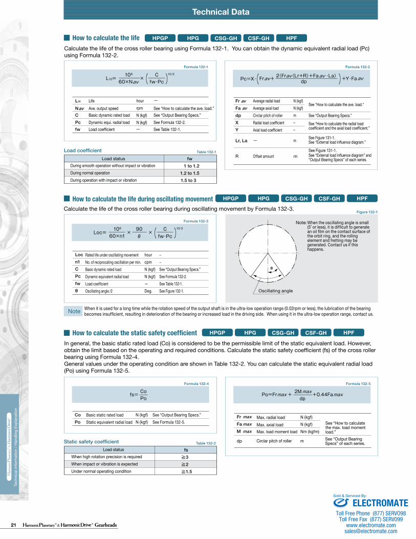
21 Gearheads
Technical DataTechnical Data Technical Data
230 231
Tech
nica
l Inf
orm
atio
n / H
andl
ing
Expl
anat
ion
Tech
nica
l Inf
orm
atio
n / H
andl
ing
Expl
anat
ion
HPG HPF
Calculate:Maximum load moment load (Mi max)Maximum load axial load (Fai max)Maximum load radial load (Fri max)
Calculate:Average moment load (Mi av)Average axial load (Fai av) Average input speed (Ni av)
Maximum load moment load (Mi max) ≦ Permissible moment load (Mc)Maximum load axial load (Fai max) ≦ Permissible axial load (Fac)Maximum load radial load (Fri max) ≦ Permissible radial load (Frc)
Calculate the life and check it.
(2) Checking the life
(1) Checking maximum load
Time: t
Time: t
n1
n2
n3
M1
M2
M3
M4
n4
t1 t2 t3 t4
L10
NiCrPci
LifeAverage input rotational speedBasic dynamic rated loadDynamic equivalent radial load
HourrpmN (kgf)N
av
111420325065
0.137 × Mi av + 1.232 × Fai av0.444 × Mi av + 1.426 × Fai av
0.041 × Mi av + 1.232 × Fai av
0.109 × Mi av + 1.232 × Fai av0.071 × Mi av + 1.232 × Fai av0.053 × Mi av + 1.232 × Fai av
maxmax
Fai
Lri
Fri
Lai
111420325065
111420325065
2532
2532
*1 The allowable axial load is the tolerance of an axial load applied to the shaft center.*2 The allowable radial load of HPG series is the tolerance of a radial load applied to the shaft length center.*3 The allowable radial load of HPG series is the tolerance of a radial load applied to the point of 20 mm from the shaft edge (input flange edge).
2532 106 × Mi av + 2.7 × Fai av
121 × Mi av + 2.7 × Fai av
Fai
Fri
Lai
Lri
Check the maximum load and life of the bearing on the input side if the reducer is an HPG input shaft unit or an HPF hollow shaft unit.
FriFaiLri,Lai
The specification of the input side main bearing of the input shaft unit is shown below.
If moment load and axial load fluctuate, they should be converted into the average load to check the life of the bearing.
Calculate the bearing life according to Calculation Formula 132-5 and check the life.
Specification of input shaft bearing
Specification of input shaft bearing
Table 133-1
Table 134-1
Table 134-2
Figure 134-1
Formula 134-2
Formula 134-3
Formula 134-4
Graph 134-1
Formula 134-5
Table 133-2
Size
Table 133-3
Table 133-4
〔Note: Table 133-2 and 133-4〕
External load influence diagram
Dynamic equivalent radial load
Size
Dynamic equivalent radial load
HPG HPF
HPG
HPF
HPG HPF
HPG
HPF
Pci
N270058009700
225003550051000
kgf275590990
230036005200
N127031505600148002510039500
kgf129320570151025604050
Nm0.166.313.544.496.9210
kgfm0.0160.641.384.539.8821.4
N2456571206328555408600
kgf2567123335565878
N20.6500902197032265267
kgf2.15192
201329537
N1450029700
kgf14803030
N1010020100
kgf10302050
Nm1019
kgfm1.021.93
N15383263
kgf157333
N522966
kgf53.298.5
Pci
HPG HPF
Formula 134-1
Checking procedure
Specification of input shaft bearing
SizeBasic rated load
Basic dynamic rated load Cr Basic static rated load Cor
SizeAllowable moment load Mc Allowable axial load Fac *1 Allowable radial load Frc *2
SizeBasic rated load
Basic dynamic rated load Cr Basic static rated load Cor
SizeAllowable moment load Mc Allowable axial load Fac *1 Allowable radial load Frc *3
Calculating maximum load moment load to input shaft
How to calculate average load(Average moment load, average axial load, average input rotational frequency)
Mi max ≦ Mc (Permissible moment load)Fai max ≦ Fac (Permissible axial load)
Max. radial loadMax. axial load————
N (kgf)N (kgf)m
See Fig. 134-1.See Fig. 134-1.See Fig. 134-1.
The maximum load moment load (Mi max ) is calculated as follows.Check that the following formulas are established in all circumstances:
Inpu
t spe
edM
omen
t loa
d
How to calculate the average moment load (Miav )
How to calculate the average axial load (Faiav)
How to calculate the average output rotational frequency (Niav)
Calculating life of input side bearing
Miav Average moment load Nm (kgfm) See Formula 134-2Faiav Average axial load N (kgf) See Formula 134-3
See Formula 134-4See Table 133-1 and -3See Table 134-1 and -2
Input Bearing Specifications and Checking Procedure
228 229
Tech
nica
l Inf
orm
atio
n / H
andl
ing
Expl
anat
ion
Tech
nica
l Inf
orm
atio
n / H
andl
ing
Expl
anat
ion
Technical Data Technical Data
HPG HPFCSG-GH CSF-GHHPGPHow to calculate the maximum load moment load
How to calculate the radial load coefficient and the axial load coefficient
The radial load coefficient (X) and the axial load coefficient (Y)
HPGHPF
CSG-GHCSF-GH
HPG HPFCSG-GH CSF-GH
HPG HPFCSG-GH CSF-GHHPGP
HPG HPFCSG-GH CSF-GHHPGP
HPGP
HPGHPF
CSG-GHCSF-GH
HPGP
HPGP
Formula 131-1
Formula 131-3
Formula 131-4
Formula 131-5
Formula 131-2
Figure 131-1
Load coefficient
Static safety coefficient
Formula 132-1
Table 132-1
Table 132-2
Formula 132-3
Figure 132-1
Formula 132-4 Formula 132-5
Formula 132-2
Note
Note that the maximum axial load within the t1 section is Fr1 and the maximum axial load within the t3 section is Fr3.
Note that the maximum axial load within the t1 section is Fr1 and the maximum axial load within the t3 section is Fr3.
Fr1
Fr2
Fr4
Fa1
Fa2
Fa4
Fa3t1 t2 t3 t4
n1
n2
n4
n3
Fr3
Time
Time
Time
N (kgf)
N (kgf)
m
m
M =Fr (Lr+R)+Fa ・ Lamax max max
N (kgf)
N (kgf)
m
m
m
Fr
Fa
Lr, La
R
dp
av
av
1
0.67 0.67
0.45≦1.5Fa
Fr +2(Fr (Lr+R)+Fa ・La)/dpavav avav
>1.5FaFr +2(Fr (Lr+R)+Fa ・La)/dpavav av
av
hourrpmN (kgf)N (kgf)
N (kgf)N (kgf)m––
m
FrFadpXY
Lr, La
avav
Locn1CPcfwθ
Rated life under oscillating movementNo. of reciprocating oscillation per min.Basic dynamic rated loadDynamic equivalent radial load Load coefficientOscillating angle /2
hourcpmN (kgf)N (kgf)—Deg.
−−See “Output Bearing Specs.” See Formula 132-2.See Table 132-1.See Figure 132-1.
Basic static rated loadStatic equivalent radial load
N (kgf)N (kgf)
See “Output Bearing Specs.” See Formula 132-5.
FrFaM
N (kgf)N (kgf)Nm (kgfm)
See “Output Bearing Specs” of each series. mdp
maxmaxmax
When it is used for a long time while the rotation speed of the output shaft is in the ultra-low operation range (0.02rpm or less), the lubrication of the bearing becomes insufficient, resulting in deterioration of the bearing or increased load in the driving side. When using it in the ultra-low operation range, contact us.
See “Specification of main bearing” of each series
See “Output Shaft Bearing Specifications” of each series.
During smooth operation without impact or vibrationDuring normal operationDuring operation with impact or vibration
When high rotation precision is requiredWhen impact or vibration is expectedUnder normal operating condition
≧3≧2≧1.5
How to obtain the average radial load (Fr )av
How to obtain the average axial load (Fa )av
How to obtain the average output rotational frequency (N )av
Fr
Fa
Lr, La
R
max
max
X Y
Calculate the life of the cross roller bearing during oscillating movement by Formula 132-3.
If the radial load and the axial load fluctuate, they should be converted into the average load to check the life of the cross roller bearing.
Formula
L10
NavCPcfw
See “How to calculate the ave. load.”See “Output Bearing Specs.” See Formula 132-2.See Table 132-1.
LifeAve. output speedBasic dynamic rated loadDynamic equi. radial loadLoad coefficient
Load status fw 1 to 1.21.2 to 1.51.5 to 3
fs
CoPo
dp
RLrFa
La
Fr
θ
Oscillating angle
Note:
maxmax
Max. radial load
Max. axial load
Offset amount
See Fig. 131-1.
See Fig. 131-1.
See Fig. 131-1.
See Fig. 131-1.
Average radial load
Average axial load
Offset amount
Circlar pitch of roller
See “How to obtain the average load.”
See “How to obtain the average load.”
See Fig. 131-1.
See Fig. 131-1.
See “Output Shaft Bearing Specifications” of each series. See Fig. 131-1.
How to calculate the average load (Average radial load, average axial load, average output rotational frequency)
Radi
al lo
adAx
ial l
oad
Outp
ut ro
tatio
nal
frequ
ency
Load
Radial load
Axial load
Calculate the life of the cross roller bearing using Formula 132-1. You can obtain the dynamic equivalent radial load (Pc) using Formula 132-2.
How to calculate the life
How to calculate the life during oscillating movement
How to calculate the static safety coefficient
Average radial loadAverage axial loadCirclar pitch of roller Radial load coefficientAxial load coefficient
Offset amount mR
See "How to calculate the ave. load."
See “Output Bearing Specs.”
See “How to calculate the radial load coefficient and the axial load coefficient.”
See Figure 131-1. See “External load influence diagram.”
See Figure 131-1.See “External load influence diagram” and “Output Bearing Specs” of each series.
When the oscillating angle is small (5˚ or less), it is difficult to generate an oil film on the contact surface of the orbit ring, and the rolling element and fretting may be generated. Contact us if this happens.
In general, the basic static rated load (Co) is considered to be the permissible limit of the static equivalent load. However, obtain the limit based on the operating and required conditions. Calculate the static safety coefficient (fs) of the cross roller bearing using Formula 132-4. General values under the operating condition are shown in Table 132-2. You can calculate the static equivalent radial load (Po) using Formula 132-5.
Load status
Max. radial loadMax. axial load See “How to calculate
the max. load moment load.”Max. load moment load
Circlar pitch of roller
ELECTROMATEToll Free Phone (877) SERVO98
Toll Free Fax (877) SERV099www.electromate.com
Sold & Serviced By:

22 GearheadsRev 02-15
Group Companies Harmonic Drive Systems, Inc. 6-25-3 Minami-Ohi, Shinagawa-ku Tokyo 141-0013, Japan
Harmonic Drive AG Hoenbergstrasse, 14, D-6555 Limburg/Lahn Germany
Harmonic Drive® and HarmonicPlanetary® are registered trademarks and Quick Connect is a trademark of Harmonic Drive LLC. All other trade-marks are property of their respective owners.
Harmonic Drive LLCBoston US Headquarters247 Lynnfield Street Peabody, MA 01960
New York Sales Office100 Motor ParkwaySuite 116Hauppauge, NY 11788
California Sales Office333 W. San Carlos Street Suite 1070San Jose, CA 95110
Chicago Sales Office137 N. Oak Park Ave., Suite 410Oak Park, IL 60301
T: 800.921.3332 T: 978.532.1800 F: 978.532.9406
www.HarmonicDrive.net ELECTROMATEToll Free Phone (877) SERVO98
Toll Free Fax (877) SERV099www.electromate.com
Sold & Serviced By:


![CSF - 03.i Valvulas Bola Serie (IND).ppt [Sólo lectura] › pricelists › csf › CSF - 03.i Valvulas Bola...Microsoft PowerPoint - CSF - 03.i Valvulas Bola Serie (IND).ppt [Sólo](https://img.pdfslide.tips/doc/110x75/5f0c01a57e708231d4334b45/csf-03i-valvulas-bola-serie-indppt-slo-lectura-a-pricelists-a-csf.jpg)

![Entwicklung von Harmonic Drive® Getriebe für Raumfahrtantriebe · 1. einleitung +duprqlf 'ulyh *hwulheh zhughq vfkrq vhlw-dku]hkqwhq lq ghu 5dxpidkuw xqg 3odqhwhqhunxqgxqjhlqjhvhw]w](https://img.pdfslide.tips/doc/110x75/5d62c35188c99362608b6c10/entwicklung-von-harmonic-drive-getriebe-fuer-1-einleitung-duprqlf-ulyh.jpg)