Embed Size (px)
Citation preview
7/27/2019 10.1.1.99.8330
http://slidepdf.com/reader/full/1011998330 1/8
Testing Real-Time Embedded Software usingUPPAAL-TRON
An Industrial Case Study
Kim G. Larsen Marius Mikucionis Brian Nielsen Arne Skou
Center of Embedded Software Systems, CISSAalborg University
Fredrik Bajersvej 7B, DK9220 Aalborg, Denmark
Email: { kgl | marius | bnielsen | ask}@cs.aau.dk
ABSTRACT
UPPAAL-TRON is a new tool for model based online black-boxconformance testing of real-time embedded systems specified astimed automata. In this paper we present our experiences in apply-
ing our tool and technique on an industrial case study. We concludethat the tool and technique is applicable to practical systems, andthat it has promising error detection potential and execution perfor-mance.
Categories and Subject Descriptors
D.2 [Software Engineering]: Miscellaneous; D.2.5 [Software En-
gineering]: Testing and Debugging—symbolic execution, moni-
tors, testing tools
General Terms
Algorithms, Experimentation, Languages, Theory, Verification
KeywordsBlack-box testing, online testing, embedded systems, control soft-ware, real-time systems
1. INTRODUCTIONModel-based testing is a promising approach for improving the
testing of embedded systems. Given an abstract formalized model(ideally developed as the design process) of the behaviour of as-pects of the implementation under test (IUT), a test generation toolautomatically explores the state-space of the model to generate validand interesting test cases that can be executed against the IUT. Themodel specifies the required and allowed behavior of the IUT.
UPPAAL is a mature integrated tool environment for modeling,verification, simulation, and testing of real-time systems modeled
as networks of timed automata [8]. UPPAAL-TRON (TRON for
Permission to make digital or hard copies of all or part of this work forpersonal or classroom use is granted without fee provided that copies arenot made or distributed for profit or commercial advantage and that copiesbear this notice and the full citation on the first page. To copy otherwise, torepublish, to post on servers or to redistribute to lists, requires prior specificpermission and/or a fee.
EMSOFT’05, September 19–22, 2005, Jersey City, New Jersey, USA.Copyright 2005 ACM 1595930914/05/0009 ...$5.00.
short) is a recent addition to the U PPAAL environment. It per-forms model-based black-box conformance testing of the real-timeconstraints of embedded systems. TRON is an online testing toolwhich means that it, at the same time, both generates and exe-cutes tests event-by-event in real-time. TRON represents a novel
approach to testing real-time systems, and is based on recent ad-vances in the analysis of timed automata. Applying TRON on smallexamples has shown promising error detection capability and per-formance.
In this paper we present our experiences in applying TRON on anindustrial case study. Danfoss is a Danish company known world-wide for leadership in Refrigeration & Air Conditioning, Heating& Water and Motion Controls [2]. The IUT, EKC 201/301, is anadvanced electronic thermostat regulator sold world-wide in highvolume. The goal of the case study is to evaluate the feasibility of our technique on a practical example.
TRON replaces the environment of the IUT. It performs two log-ical functions, stimulation and monitoring. Based on the timed se-quence of input and output actions performed so far, it stimulates
the IUT with input that is deemed relevant by the model. At thesame time it monitors the outputs and checks the conformance of these against the behavior specified in the model. Thus, TRONimplements a closed-loop testing system.
To perform these functions TRON computes the set of states thatthe model can possibly occupy after the timed trace observed so far.Thus, central to our approach is the idea of symbolically comput-ing the current possible set of states. For timed automata this wasfirst proposed by Tripakis [16] in the context of failure diagnosis.Later that work has been extended by Krichen and Tripakis [9] toonline testing from timed automata. The monitoring aspect of thiswork has been applied to NASA’s Mars Rover Controller where ex-isting traces are checked for conformance against given executionplans translated into timed automata [15]. In contrast, the work presented in this paper performs real-time online black-box test-
ing (both real-time stimulation and conformance checking) for areal industrial embedded device consisting of hardware and soft-ware. Online testing based on timed CSP specifications has beenproposed and applied in practice by Peleska [14].
Our approach, previously presented in [5, 13, 11]; an abstractappeared in [12]), uses the mature U PPAAL language and model-checking engine to perform relativized timed input/output confor-
mance testing, meaning that we take environment assumptions ex-plicitly into account.
Compared to current control engineering testing practices, our

7/27/2019 10.1.1.99.8330
http://slidepdf.com/reader/full/1011998330 2/8
emphasis is on testing discrete mode switches (possibly non-deter-ministic) and on real physical time constraints (deadlines) on ob-servable input/output actions, and less on continuous state evolu-tion characterized by differential equations. Also many engineer-ing based approaches has no general formal correctness criteria,and correctness is assessed manually (tool assisted) by correlatinga simulated-model with observed test data. In our case we havean explicit correctness relation allowing us to automatically mapevents and timings into model and assign verdicts to the observed
behavior online. It is also important to remark that our environmentmodels need not represent a single deterministic scenario, but rep-resents all relevant environment behaviors/assumptions from whichsamples are randomly chosen during test execution. On the otherhand, the strong focus and dependency on environment modelscommon in control engineering testing appear new to formal soft-ware testing.
In Section 2 we introduce the concepts behind our testing frame-work. Section 3 describes the case, Section 4 our modeling experi-ences, and Section 5 performance results. Section 6 concludes thepaper.
2. TESTING FRAMEWORKThe most important ingredients in our framework is relativized
conformance, timed automata, environment modeling, and the testgeneration algorithm.
2.1 Relativized Conformance TestingAn embedded system interacts closely with its environment which
typically consists of the controlled physical equipment (the plant)accessible via sensors and actuators, other computer based systemsor digital devices accessible via communication networks usingdedicated protocols, and human users. A major development task is to ensure that an embedded system works correctly in its realoperating environment.
The goal of (relativized) conformance testing is to check whetherthe behavior of the IUT is correct according to its specification un-der assumptions about the behavior of the actual environment inwhich it is supposed to work. In general, only the correctness inthis environment needs to be established, or it may be too costly orineffective to achieve for the most general environment. Explicitenvironment models have many other practical applications.
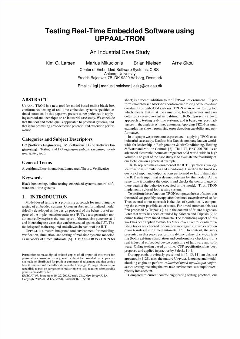
Figure 1 shows the test setup. The test specification is a network of timed automata partitioned into a model of the environment of the IUT and the IUT. TRON replaces the environment of the IUT,and based on the timed sequence of input and output actions per-formed so far, it stimulates the IUT with input that is deemed rel-evant by the environment part of the model. Also in real-time itchecks the conformance of the produced timed input output se-quence against the IUT part of the model. We assume that theIUT is a black-box whose state is not directly observable. Onlyinput/output actions are observable. The adapter is an IUT specifichardware/software component that connects TRON to the IUT. It
is responsible for translating abstract input test events into physicalstimuli and physical IUT output observations into abstract modeloutputs. It is important to note that we currently assume that inputsand outputs are discrete (or discretized) actions, and not continu-ously evolving.
Depending on the construction of the adapter, TRON can be con-nected to the hardware (possibly via sensors and actuators) withembedded software forming hardware-in-the-loop testing, or it canbe connected directly to the software forming software-in-the-looptesting.
We extended the input/output conformance relation ioco [17] be-
ImplementationEnvironmentassumptions specification
Simulated Environment
in!
out!
in?
"in"
out? Under Test
Implementation
output
input
"out"
A d a p t e r
A d a p t e r A P I
UPPAAL−TRON engine
P h y s i c a l A P I
Figure 1: TRON test setup.
tween a formal specification and its black-box implementation tothe timed setting and relatively to a given environment.
Intuitively i rtiocoe s means that after executing any timed in-put/output trace σ that is possible in the composition of the systemspecification s and environment specification e, the implementa-tion i in environment e may only produce outputs and timed delayswhich are included in the specification s under environment e. Rel-ativized timed input/output conformance rtioco [6] is definedformally in Equation 1.
i rtiocoe s = ∀σ ∈ TTr(s, e). out`
(i, e) after σ´
⊆out
`(s, e) after σ
´ (1)
Here after σ denotes the set of states the specification system(s, e) (resp. implementation system (i, e)) may possibly occupyafter executing the timed i/o trace σ. out
`´denotes the possible
outputs (including permissible delays) the system can produce froma given set of states.
The output inclusion in the relation guarantees both functionaland time-wise correctness. The IUT is not allowed produce anyoutput actions (including the special output of letting time pass andnot producing outputs in time) at a time they could not be done bythe specification.
2.2 Timed AutomataWe assume that a formal specification can be modeled as a net-
work of timed automata. We explain timed automaton by example,and refer to [1] for formal syntax and semantics. A timed automa-ton is essentially a finite state machine with input/output actions(distinguished respectively by ? and !) augmented with discretevariables and a set of special real-valued clock variables whichmodels the time.
Clocks and discrete variables may be used in predicates on tran-sitions (called guards) to define when thetransitions may take place.A location invariant is a clock predicate on an automaton locationthat defines for how long the automaton is allowed to stay in thatlocation, thus forcing the automaton to make progress within thespecified time bounds. On transitions, the variables can be assigneda value, and clocks may be reset to zero.
Figure 2(a) shows an U PPAAL automaton of a simple coolingcontroller Cr where x is real-valued clock and r is an integer con-stant. Its goal is to control and keep the room temperature in Med
range. The controller is required: 1) to turn On the cooling de-vice within an allowed reaction time r when the room temperaturereaches High range, and 2) to turn it Off within r when the temper-ature drops to Low range.
In the encircled initial location off , it forever awaits temperatureinput samples Low, Med and High. When Cr receives High it resetsthe clock x to zero and moves to location up, where the locationinvariant x ≤ r allows it to remain for at most r time units. Edgesmay also have guards which define when the transition is enabled(see e.g. in Figure 2(d)). At latest when x reaches r time unitsthe output on is generated. If a Low is received in the mean time

7/27/2019 10.1.1.99.8330
http://slidepdf.com/reader/full/1011998330 3/8
it must go back off . Transitions are taken instantaneously and timeonly elapses in locations.
In location off the automaton reacts non-deterministically to in-put Med : Cr may choose either to take a loop transition and stay inlocation off or move to location up. When Cr is used as a specifi-cation a relativized input/output conforming controller implemen-tation may choose to perform either. Thus non-determinism givesthe implementation some freedom. There are two sources of non-determinism in timed automata: 1) in the timing (tolerances) of
actions as allowed by location invariants and guards, and 2) in thepossible state after an action.
Timed automata may be composed in parallel, communicate viashared variables and synchronize rendezvous-style on matching in-put/output transitions. In a closed timed automata network all out-put action transitions have a corresponding input action transition.
UPPAAL is an model checker for real-time systems, and supportstimed automata networks with additional integer variable types,broadcast (one-to-many) synchronizations and other extensions. UP-PAAL provides an efficient set of symbolic model-checking algo-rithms for performing symbolic reachability analysis of timed au-tomata. Since clock values are real-valued, the state-space of themodel is infinite, and cannot be represented and computed explic-itly. A symbolic state represents a (potentially infinite) set of con-
crete states and is implemented as particular set of linear inequa-tions on clock variables. Thus the evaluation of guards and compu-tation of successor symbolic states is done symbolically.
2.3 Environment ModelingIn this section we exemplify how our conformance relation dis-
criminates systems, and illustrate the potential power of environ-ment assumptions and how this can help to increase the relevanceof the generated tests for a given environment.
Consider the simple cooling controller of Figure 2(a) and theenvironment in Figure 2(c). Take C6 to be the specification and as-sume that the implementation behaves like C8. Clearly, C8 rt iocoEM
C6 because the timed trace 0·Med ! ·7·On ! is possible in the imple-mentation, but not in the specification. Formally, out
`C8
after 0·
Med !·7´
= {On !}∪R≥0 ⊆ out`
C6after 0·Med !·7
´= R≥0
(recall that C r may remain in location off on input Med and notproduce any output). The implementation can thus perform an out-put at a time not allowed by the specification.
Next, suppose Cr is implemented by a timed automaton Cr equal
to Cr, except the transition upLow
−−→ dn is missing, and replacedby a self loop in location up. They are distinguishable by the timedtrace 0· Med?·0· High?·0· Low?·0· On! in the implementation thatis not in the specification (switches the compressor Off instead).
Figures 2(b) to 2(e) show four possible environment assump-tions for Cr. Figure 2(c) shows the universal and completely un-constrained environment E M where room temperature may changeunconstrained and may change (discretely) with any rate. This isthe most discriminating environment that can generate any inputoutput sequence and thus (in principle) detect all errors.
This may not be realistic in the given physical environment, andthere may be less need to test the controller in such an environ-ment, as temperature normally evolves slowly and continuously,e.g., it cannot change drastically from Low to High and back un-less through Med . Similarly, most embedded and real-time systemsalso interact with physical environments and other digital systemsthat— depending on circumstances—can be assumed to be correctand correctly communicate using well defined interfaces and pro-tocols. The other extreme in Figure 2(c) is the least discriminatingenvironment; it merely passively consumes output actions.
Figure 2(d) shows the environment model E d1 where the temper-
ature changes through Med range and with a speed bounded byd. Figure 2(e) shows an even more constrained environment E 2that assumes that the cooling device works, e.g., temperature neverincreases when cooling is on. Notice that E 2 and E 1 have less dis-criminating power and thus may not reveal faults found under morediscriminating environments. However, if the erroneous behavioris impossible in the actual operating environment the error may
be irrelevant. Consider again the implementation Cr from above.
This error can be detected under E 0 and E 3d<r1 via the timed tracethat respects the environments d· Med?·d· High?·d· Med?·d· Low?·ε·On!, ε ≤ r. The specification would produce Off . The error cannotbe detected under E 1 if it too slow 3d > r, and never under E 2 forno value of d.
In the extreme the environment behavior can be so restricted thatit only reflects a single test scenario that should be tested. In ourview, the environment assumptions should be specified explicitlyand separately.
2.4 Online Testing Algorithm.Here we outline the algorithm behind TRON informally. The
precise formal definitions and algorithms behind TRON have beendocumented in [12, 11, 6, 7] and we refer to these for further details.
The environment model functions as a (state-dependent) input-
stimuli (load) generator. The IUT-model functions as as a test ora-cle, and is used to evaluate the correctness of the observed timed in-put output sequence. In order to simulate the environment and mon-itor the implementation, Algorithm 1 maintains the current reach-able symbolic state set Z ⊆ S × E that the test specification canpossibly occupy after the timed trace observed so far.
Based on this symbolic state-set, TRON checks whether the ob-served output actions and timed delays are permitted in the specifi-cation. In addition TRON computes the set of possible inputs thatmay be offered to the implementation.
ALG . 1. Test generation and execution: Z := {(s0, e0)}.
while Z = ∅ ∧ iterations ≤ T do choose randomly:
offer input action:
if EnvOutput(Z ) = ∅randomly choose i ∈ EnvOutput(Z )send i to IUT, Z := Z after i
delay and wait for an output:
randomly choose d ∈ Delays(Z )sleep d or wake up on output o at d ≤ dif o occurs then
Z := Z after d
if o /∈ ImpOutput(Z ) then return failelse Z := Z after o
else Z := Z after dreset and restart: Z := {(s0, e0)} , reset IUT
if Z = ∅ then return fail else return pass
TRON randomly chooses between one of three basic actions: ei-
ther send a randomly selected relevant input to the IUT, letting timepass by some (random) amount and silently observe the IUT foroutputs, or reset the IUT and restart. The set of input actions thatare possible in the current state-set Z (enabled environment output)is denoted by EnvOutput(Z ). Similarly, ImpOutput(Z ) denotesthe allowed set of implementation outputs, and Delays(Z ) the pos-sible delays before the tester must give an input to the IUT (as con-strained by invariants the environment model). In the practical im-plementation the probability of restarting is chosen comparativelyvery low.
If the tester observes an output or a time delay it checks whether

7/27/2019 10.1.1.99.8330
http://slidepdf.com/reader/full/1011998330 4/8
off
upx<=r
dnx<=r
on
High?x:=0
Med?
Med?x:=0
On!x:=0
Med?x:=0
Low?
Low?x:=0
High?Med?
Off!x:=0
High?x:=0
Low?
x:=0
Med? Med?
High?Low?
(a) Cr: simple cooling con-troller.
On?
Off?
(b) E L
On?
Off?
Low!
Med!
High!
(c) E M .
H
M
L
On?Off?
y>=dLow!
y:=0
y>=dMed!y:=0
y>=dHigh!y:=0
y>=dMed!
y:=0
Off? On?
Off? On?
(d) E d1 .
OnHighy<=step
OnMedy<=step
OnLowOffLowy<=step
OffMedy<=step
OffHigh
On?
y>=d
Low!y:=0
y>=dMed!y:=0
y>=dHigh!y:=0
y>=d
Med!y:=0Off?
On?
Off?
On?
Off?
(e) E d,s2
.
Figure 2: Timed automata of simple controller and various environments.
this is legalaccording to the state set. The state set is updated when-ever an input is offered, an output or a delay is observed. Considerthe system (Cr, E d1 ). The initial state-set is the single symbolicstate: {off ,L, x = 0 ∧ y = 0}. After a delay of d or more,{Med } is the set of possible inputs. Suppose that TRON issues
Med after δ ≥ d time units. The state-set now consists of twostates: {off ,M , x = δ ∧ y = 0, up,M , x = 0 ∧ y = 0}. If On is received later at time δ ≤ r the first element in the state-setwill be eliminated resulting in {on ,M , x = 0 ∧ y = δ }. Illegaloccurrence or absence of an output is detected if the state set be-comes empty which is the result if the observed trace is not in thespecification.
TRON uses using the UPPAAL engine to traverse internal, de-
lay and observed action transitions, to evaluate clock and variableguards, and to perform variable assignments. We use the efficientreachability algorithm implementation [3] to implement the op-erator after . It operates on bounded symbolic states, checksfor symbolic-state inclusions and thus always terminates even if the model contains loops of internal actions. Further informationabout the implementation of the required symbolic operations canbe found in [6].
Currently TRON is available to download via the Internet free of charge for evaluation, research, education and other non-commercialpurposes [10]. TRON supports all UPPAAL modeling features in-cluding non-determinism, provides timed traces as test log and averdict as the answer to rtioco relation, and features for model-coverage measurements.
3. THE DANFOSS EKC201 REFRIGERA
TION CONTROLLERWe applied UPPAAL-TRON on a first industrial case study pro-
vided by Danfoss Refrigeration Controls Division. The EKC con-trols and monitors the temperature of industrial cooling plants suchas cooling and freezer rooms and large supermarket refrigerators.
3.1 Control ObjectiveThe main control objective is to keep the refrigerator room air
temperature at a user defined set-point by switching a compressoron and off. It monitors the actual room temperature, and soundsan alarm if the temperature is too high (or too low) for too long aperiod. In addition it offers a myriad of features (e.g. defrostingand safety modes in case of sensor errors) and approximately 40configurable parameters.
The EKC obtains input from a room air temperature sensor, adefrost temperature sensor, and a two-button keypad that controlsapproximately 40 user configurable parameters. It delivers outputvia a compressor relay, a defrost relay, an alarm relay, a fan re-lay, and a LED display unit showing the currently calculated roomair temperature as well as indicators for alarm, error and operatingmode.
Figure 3 shows a simplified view of control objective, namely tokeep the temperature within setPoint and setPoint +differential de-grees. The regulation is to be based on an weighted averaged roomtemperature T n calculated by the EKC by periodically sampling(around 1.2 sec.) the air temperature sensor such that a new sampleT is weighted by 20% and the old average T n−1 by 80%:
T n =T n−1 ∗ 4 + T
5(2)
A certain minimum duration must pass between restarts of the com-pressor, and similarly the compressor must remain on for a mini-mum duration. An alarm must sound if the temperature increases(decreases) above (below) highAlarmLimit (lowAlarmLimit ) for alar-
mDelay time units. All time constants in the EKC specification arein the order of seconds to minutes, and a few even in hours.
3.2 Test Adaptation.A few comments are necessary about the test adapter for the
EKC since it determines what and how precise the IUT can be con-trolled and observed.
Internally, the EKC is organized such that nearly every input,output and important system parameter is stored in a so-called pa-rameter database in the EKC that contains the value, type and per-mitted range of each variable. The parameter database can be in-

7/27/2019 10.1.1.99.8330
http://slidepdf.com/reader/full/1011998330 5/8
Temperature
Time
setpoint
setpoint+differential
highAlarmDeviation
lowAlarmLimit
highAlarmLimit
lowAlarmDeviation
differential
startcompressor
stopcompressor
startcompressor
stopcompressor
startalarm
norma l min res ta rttime not elapsed min coolingtime not elapsed alarm delay
Figure 3: EKC Main Control Objective.
directly accessed from a visual Basic API on a MS Windows XPPC host via monitoring software provided by Danfoss. The EKC isconnected to a MS Windows XP PC host, first via a LON network from the EKC to a EKC-gateway, and from the gateway to the PCvia a RS-232 serial connection. The required hardware and soft-ware were provided by Danfoss. As recommended by Danfoss we
implemented the adaptation software by accessing the parameterdatabase using the provided interface. However, UPPAAL-TRONonly exists in UNIX versions, and thus it required a second UNIX-host computer connected to the MS windows PC using a TCP/IPconnection properly configured to prevent unnecessary delaying of small messages. The adaptation software thus consists of a “thin”visualBasic part running on the MS windows host, and a C++ partinterfacing to the TRON native adaptation API running on a UNIXhost. It is important to note that this long chain (three network hops) adds both latency and uncertainty to the timing of events.
More seriously it turned out that the parameters representing sen-sor inputs are read-only, meaning that the test host cannot changethese to emulate changes in sensor-inputs. Therefore some func-tionality (temperature based defrosting, sensor error handling, anddoor open control) related to these is not modeled and tested. Themain sensor, the room temperature, is hardwired to a fixed settingvia a resistor, but the sensed room temperature can be changed indi-rectly via a writable calibration parameter with the range ±20 ◦C .
It quickly became evident to us that the monitoring software wasmeant for “coarse grained” event logging and supervision by anoperator, not as a (real-time) test interface. An important generallesson learned is that an IUT should provide an test interface withsuitable means for control and observation. We are collaboratingwith Danfoss to provide a better test interface for future versions of the product.
3.3 Model StructureWe modeled a central subset of the functionality of the EKC as
a network of UPPAAL Timed Automata, namely basic temperature
regulation, alarm monitoring, and defrost modes with manual andautomatic controlled (fixed) periodical defrost (de)activation. Theallowed timing tolerances and timing uncertainties introduced bythe adaptation software is modeled explicitly by allowing outputevents to be produced within a certain error envelope. For example,a tolerance of 2 seconds is permitted on the compressor-relay. Ingeneral, it may be necessary to model the adaptation layer as partof the model for the system under test. The abstract input/outputactions are depicted in Figure 4.
From the beginning it was decided to challenge our tool. There-fore we decided that the model should be responsible of tracking
EKC
defrostRelayOn!
defrostRelayOff!
alarmRelayOn!
alarmRelayOff!
compressorRelayOn!
compressorRelayOff!
highAlarmDisplayOn!
highAlarmDisplayOff!
ekcReset?
manualDefrostOn?
manualDefrostOff?
CT(int -20..20 )?
setpoint(int -50..60)?
setAlarmDelay(int 0..90 )?
Figure 4: Model Inputs and Outputs.
the temperature as calculated by the EKC and base control actionson this value. To make this work, the computation part of the modeland also its real-time execution must be quite precise. This part of the model thus approximates the continuous evolution of a param-eter, and almost approaches a model of a hybrid system, which ison the limit of the capability of timed automata. An alternativewould be to monitor the precision of the calculated temperature inthe adaptation software and let that generate events (e.g., alarm-
LimitReached!) to the model as threshold values are crossed. Thiswould yield a simple and more abstract “pure” event driven model.
The model consists of 18 concurrent components (timed automata),
14 clock variables, and 14 discrete integer variables, and is thusquite large. The main components and their dependencies are de-picted in Figure 5 and explained below.
Output
Input
IUT-Model
alarmRelay
compressorRelay
tempMeasurement
compressor
newTempnewTemp
on/off on/off
Environment
TemperatureGenerator
defrostRelay
defrost
autoDefrost
on/off
defrostEventGen
alarmDisplay
on/off
highTempAlarm
Figure 5: Main Model Components
The Temperature Measurement component periodically sam-ples the temperature sensor and calculates a new estimated roomair temperature. The Compressor component controls the com-pressor relay based on the estimated room temperature, alarm anddefrost status. The High Temperature Alarm component moni-tors the alarm state of the EKC, and triggers the alarm relay if thetemperature is too high for too long. The Defrost component con-trols the events that must take place during a defrost cycle. Whendefrosting the compressor must be disengaged, and alarms mustbe suppressed until delayAfterDefrost time units after completion.Defrosting may be started manually by the user, and is engagedautomatically with a certain period. It stops when the defrostingtime has elapsed, or when stopped manually by the user. The Auto
Defrost component implements automatic periodic time based de-frosting. It automatically engages the defrost mode periodically.The Relay component models a digital physical output (compres-sor relay, defrost relay, alarm relay, alarm display) that when givena command switches on (respectively off) within a certain timebound. The Temperature Generator is a part of the environmentthat simulates the variation in room temperature, currently alter-natingly increases the temperature linearly between minimum andmaximum temperature, and the reverse. Finally, the Defrost Event
Generator environment component randomly issues user initiateddefrost start and stop commands.

7/27/2019 10.1.1.99.8330
http://slidepdf.com/reader/full/1011998330 6/8
4. COMPONENT MODELING AND
REVERSE ENGINEERINGThe modeling effort was carried out by computer scientists with-
out knowledge of that problem domain based on the EKC docu-mentation provided by Danfoss. It only consisted of the internalrequirements specification and the users manual, both in informalprose. In addition we had access to questioning the Danfoss En-gineers via email and two meetings, but no design documents or
source code were available. In addition we were given documen-tation about the EKC PC-monitoring software and associated APIallowing us to write the adaptation software.
In general the documentation was insufficient to build the model.In part this was due to a lack of a detailed understanding of theimplicit engineering knowledge of the problem domain and howprevious generations of controllers worked. But more importantlymuch functional behavior and especially timing constraints werenot explicitly defined. In general the requirements specification didnot state any timing tolerances, e.g, the allowed latency on com-pressor start and stop when the calculated temperature crosses thelower or higher thresholds.
Therefore the modeling involved a lot of experimentation to de-duce the right model and time constraints, which to some extentbest can be characterized as reverse engineering or model-learning
[4]. Typically the work proceeded by formulating a hypothesis of the behavior and timing tolerances as a model (of the selected as-pect/sub functionality), and then executing TRON to check whetheror not the EKC conformed to the model. If TRON gave a fail-verdict the model was revised (either functionally, or by looseningtime tolerances). If it passed the timing tolerances were tighteneduntil it failed. The process was then iterated a few times, and theDanfoss engineers were consulted to check whether the behavior of the determined model was acceptable.
In the following we give a few examples of this procedure.
4.1 Room Temperature Tracking.The EKC estimates the room temperature from Equation 2 based
on periodically samples of the room temperature sensor, and bases
most control actions like switching the compressor on or off on thisvalue. However, the requirements only requires a certain precisionon the sampling accuracy of the temperature sensors (±0.5 ◦C ) anda sensor sampling period of at most 2 seconds, and nothing abouthow frequently the temperature should be reevaluated. This led to aseries of tests where the temperature change rate, the sampling pe-riod, and temperature tolerance were changed to determine the bestmatching configuration. The model now uses a period of 1.2 sec-onds, and allows ± 2 seconds tolerance on compressor start/stop.
4.2 Alarm MonitoringExecuting TRON using our first version of the high temperature
alarm monitor caused TRON to give a fail-verdict: The EKC didnot raise alarms as expected. The model shown in Figure 6 as-
sumed that the user’s clearing of the alarm would reset the alarmstate of the EKC completely. The consequence of this is that theEKC should raise a new alarm within alarmDelay if the temper-ature remained above the critical limit. However, it did not, andcloser inspection showed that the EKC was still indicating hightemperature alarm in its display, even though the alarm was clearedby the user. The explanation given by Danfoss was that clearing thealarm only clears the alarm relay (stopping the alarm noise), not thealarm state which remains in effect until the temperature drops be-low the critical limit. The model was then refined, and includes the
noSound Displaying location in Figure 7.
4.3 Defrosting and Alarm Handling.A similar discrepancy between expected and actual behavior de-
tected by TRON was in the way that the alarm and defrost functionsinteracts. After a defrost the room temperature naturally risks beinghigher than the alarm limit, because cooling has been switched off during the defrost activity for an extended period of time. There-fore a high temperature alarm should be suppressed in this situationwhich can be done by configuring the EKC parameter alarmDe-
layAfterDefrost . However, reading different sections of the docu-mentation gives several possible interpretations:
1. When defrosting stops and the temperature is high, alarmsmust be postponed for alarmDelayAfterDefrost in addition tothe original alarmDelay, i.e., never alarms during a defrost.
2. Same as above (1) except it is measured from the time wherethe high alarm temperature is detected, even during a defrost.
3. When defrosting stops and the temperature is high, alarmsmust be suppressed for alarmDelayAfterDefrost , i.e., alar-
mDelayAfterDefrost replaces the original alarmDelay after adefrost until the the temperature becomes below critical, af-ter which the normal alarmDelay is used again.
The engineering department could not give an immediate answerto this (without reluctantly consulting old source code), but basedon their experiences and requirements for other products they be-lieved that 3 is the correct interpretation. Note that we are not sug-gesting that the product was implemented without a clear under-standing of the intended behavior, only that it was not clear fromits documentation.
4.4 Defrost Time Tolerance.Another discrepancy TRON found was that defrosting started
earlier than expected or was disengaged later. It turned out that theinternal timer in the EKC responsible for controlling the defrost pe-riod has a very low precision (probably because defrosting is rare(e.g., once a day) and has along duration (lasts several hours)). Thedefault tolerance used in the model on the relays thus had to be
further relaxed.
5. QUANTITATIVE EVALUATIONDuring a test-run, the testing algorithm computes, on a per timed
event basis, the set of symbolic states in the model that can bereached after the timed event trace observed so far, and generatesstimuli and checks the validity of IUT-outputs based on this state-set.
Since we use a non-deterministic model to capture the timingand threshold tolerances of the IUT and since internal events ina concurrent model may be executed in (possibly combinatoriallymany) different orders, this set will usually contain numerous pos-sible states. The state-set reflects the allowed states and behavior of the IUT, and intuitively, the larger the state-set, the more uncertain
the tester is about the state of the implementation.Since we generate and execute tests in real-time the state-set
must also be updated in real-time. Obviously, the model and thestate-set size affects how much computation time this takes, andone might question wheter doing this is feasible in practice. In thefollowing we investigate whether real-time online testing is realis-tic for practical cases, like the Danfoss EKC.
Figure 8 plots the evolution of the state-set size (number of sym-
bolic states) for a sample test run. Also plotted in the graph is theinput temperature, temperature threshold value for high tempera-ture (compressor must switch on) and high temperature alarm (the

7/27/2019 10.1.1.99.8330
http://slidepdf.com/reader/full/1011998330 7/8
alarmOfftriggered
ta<=IUT_TADelay
Sounding
S6
S7
IUT_calcTemp>
IUT_setPoint+diff+highAlarmDev-errnewTemp?ta:=0
ta==IUT_TADelayAOn!
ta:=0
clearHighAlarm?
AOff!ta:=0
IUT_calcTemp<=
IUT_setPoint+diff+highAlarmDev+err
newTemp?
initDone?ta:=0 IUT_calcTemp<=IUT_setPoint+diff+highAlarmDev+err
newTemp?
ta:=0
IUT_calcTemp>IUT_setPoint+diff+highAlarmDev-errnewTemp?
clearHighAlarm?clearHighAlarm?
Figure 6: First High Temperature Monitor.
alarmOfftriggered
ta<=IUT_TADelay+50
S5
S6
S7
sounding_Displaying
noSound_Displaying
S8
S29
postPoned
IUT_calcTemp>
IUT_setPoint+diff+highAlarmDev-errnewTemp?ta:=0
noDefrostDelay?
clearHighAlarm?
AOff!
ta:=0
IUT_calcTemp<=
IUT_setPoint+diff+highAlarmDev+err
newTemp?
ta:=0 initDone?ta:=0
IUT_calcTemp<=IUT_setPoint+diff+highAlarmDev+errnewTemp?
ta:=0
IUT_calcTemp>IUT_setPoint+diff+highAlarmDev-errnewTemp?
clearHighAlarm?clearHighAlarm?
HADOn!
IUT_calcTemp<=IUT_setPoint+diff+highAlarmDev+err
newTemp?
ta:=0
HADOff!ta:=0
IUT_calcTemp>IUT_setPoint+diff+highAlarmDev-errnewTemp?
AOn!ta>=IUT_TADelay-20
IUT_calcTemp<=IUT_setPoint+diff+highAlarmDev+err
newTemp?
IUT_calcTemp>IUT_setPoint+diff+highAlarmDev-errnewTemp?
clearHighAlarm?
Figure 7: Second High Temperature Monitor
alarm must sound if it remains high for more than alarmDelay (120sec) time units.
It is interesting to observe how the state-set size depends on themodel behavior. For instance, the first larger increase in state-setsize occurs after 55 seconds. At this time the temperature crossesthe limit where the compressor should switch on. But due to the
timing tolerances, the model does not “know” if the compressor-relay is in on-state or off-state, resulting in a larger state-set. Thestate-set size then decreases again, only to increase again at 93 sec-onds at which a manual defrost period is started. The next ma-
jor jump occurs at 120 seconds and correlates nicely with the timewhere the temperature crosses high-alarm limit and the alarm mon-itor component should switch into triggered state. Similarly, 260second into the run, the temperature drops below the threshold, andthere is no uncertainty in the alarm state. The fluctuations insidethis period is caused by a manually started and stopped defrost ses-sion. In fact 5 defrost cycles are started and stopped by the testerin this test run. The largest state-set size (960 states) occurs at 450seconds and correlates to the time-out of a defrost cycle. There isa large tolerance on the timer controlling defrosting, and hence themodel can exhibit many behaviors in this duration.
The state-set contains most often less than a few hundred states.Exploring these is unproblematic for a modern model-checking en-gine employed by TRON. Figure 9 plots the the cpu-time used toupdate the state-set for delay-actions (typically the most expensiveoperation) for 5 test-runs of our model on a Dual Pentium Xeon 2.8GHz CPU (one used). It can be seen that the far majority of stateset sizes are reasonably small. Updating medium sized state-setswith around 100 states requires only a few milli-seconds (ms) of cpu-time. The largest encountered state-sets (around 3000 states)are very infrequent, and requires around 300 ms.
Real-time online testing thus appear feasible for a large range of embedded systems, but also that very non-deterministic model suchas the EKC-model may limit the granularity of time constraints thatcan be checked in real-time.
Figure 8: Evolution of State-set.
6. CONCLUSIONS AND FUTURE WORKOur modeling effort shows that it is possible to accurately model
the behavior of EKC like devices as Timed Automata and use theresulting model as a test specification for online testing.
It is possible to model only selected desired aspects of the systembehavior, i.e. a complete and detailed behavioral description is notrequired for system testing. Thus, model based testing is feasibleeven if a clear and complete formal model is not available from the

7/27/2019 10.1.1.99.8330
http://slidepdf.com/reader/full/1011998330 8/8
0 500 1000 1500 2000 2500 3000 3500
0
5 0 0 0 0
1 0 0 0 0 0
1 5 0
0 0 0
2 0 0 0 0 0
2 5 0 0 0 0
3 0 0 0 0 0
Initial state set size
A v e r a g e a f t e r D e l a y
C P U
t i m e , m i c r o s e c o n d s
Figure 9: Cost of State-set Update: Delay action
start, although it will clearly benefit from more explicit modeling
during requirements analysis and system design.In the relative short testing time, we found many discrepanciesbetween our model and the implementation. Although many of these were caused by a wrong model due to incomplete require-ments or mis-interpretations of the documentation, and not actualimplementation errors, our work indicates that online testing seemsan effective technique to find discrepancies between the expectedmodel behavior and actual behavior of the implementation undertest. Thus there are also reasons to believe that it is effective indetecting actual implementation errors.
It should be mentioned that the EKC is a mature product thathas been produced and sold for a number of years. Future work includes testing a less mature version of a EKC like controller.
Performance-wise we conclude that real-time online testing ap-pear feasible for a large range of embedded systems. To target
even faster real-time systems with even time constraints in the (sub)milli-second range we plan to separate our tool into two parts, anenvironment emulation part, and a IUT monitoring part. Monitor-ing need not be performed in real-time, and may in the extreme bedone offline. The model that will need to be interpreted in real-timeis thus much smaller and can be done much faster.
We are extending our tool with coverage measurements, cover-age based guiding, and features for error diagnosis. By import-ing a trace collected during a test run into U PPAAL it can be runagainst the IUT model. It can also be replayed against the ac-tual IUT (within the limits of non-determinism). Future work alsoincludes extensions for testing hybrid systems, i.e., systems withgeneral continous state evolution besides progress of time, e.g. byusing hybrid automata, but analyzing such systems exactly and for-mally is much more difficult and costly.
Acknowledgments
We would like to thank Danfoss for providing the case-study andespecially Finn Andersen, Peter Eriksen, and Søren Winkler Ras-mussen from Danfoss for engagement and constructive informationand help during the project.
7. REFERENCES[1] R. Alur and D. Dill. A Theory of Timed Automata.
Theoretical Comput. Sci., 126(2):183–235, Apr. 1994.
[2] D. A/S. Danfoss internet website, http://www.danfoss.dk.
[3] G. Behrmann, J. Bengtsson, A. David, K. Larsen,P. Pettersson, and W. Yi. Uppaal implementation secrets. InFormal Techniques in Real-Time and Fault-Tolerant Systems:
7th International Symposium, FTRTFT 2002, pages 3–22,September 2002.
[4] T. Berg, B. Jonsson, M. Leucker, and M. S. August. Insightsto Angluin’s Learning. In International Workshop on
Software Verification and Validation (SVV 2003), 2003.
[5] E. Brinksma, K. Larsen, B. Nielsen, and J. Tretmans.Systematic Testing of Realtime Embedded Software Systems(STRESS), March 2002. Research proposal submitted andaccepted by the Dutch Research Council.
[6] K. Larsen, M. Mikucionis, and B. Nielsen. Online testing of real-time systems using UPPAAL. In Formal Approaches to
Testing of Software, Linz, Austria, September 21 2004.Lecture Notes in Computer Science.
[7] K. Larsen, M. Mikucionis, and B. Nielsen. Online Testing of Real-time Systems using Uppaal: Status and Future Work. InE. Brinksma, W. Grieskamp, J. Tretmans, and E. Weyuker,editors, Dagstuhl Seminar Proceedings volume 04371:
Perspectives of Model-Based Tes ting, Schloss Dagstuhl,D-66687 Wadern, Germany., September 2004. IBFI gem.
GmbH, Schloss Dagstuhl.[8] K. Larsen, P. Pettersson, and W. Yi. UppAal in a Nutshell.
International Journal on Software Tools for Technology
Transfer , 1(1):134–152, 1997.
[9] M. Krichen and S. Tripakis. Black-box Conformance Testingfor Real-Time Systems. In Model Checking Software: 11th
International SPIN Workshop, volume LNCS 2989. Springer,April 2004.
[10] M. Mikucionis. Uppaal tron internet page,http://www.cs.aau.dk/˜marius/tron.
[11] M. Mikucionis, K. Larsen, and B. Nielsen. Online on-the-flytesting of real-time systems. Technical Report RS-03-49,Basic Research In Computer Science (BRICS), Dec. 2003.
[12] M. Mikucionis, B. Nielsen, and K. Larsen. Real-time system
testing on-the-fly. In the 15th Nordic Workshop onProgramming Theory, number 34 in B, pages 36–38, Turku,Finland, October 29–31 2003. Abo Akademi, Department of Computer Science, Finland. Abstracts.
[13] M. Mikucionis and E. Sasnauskaite. On-the-fly testing usingUPPAAL . Master’s thesis, Department of Computer Science,Aalborg University, Denmark, June 2003.
[14] J. Peleska. Formal Methods for Test Automation - HardReal-Time Testing of Controllers f or the Airbus AircraftFamilies. In Integrated Design and Process Technology
(IDPT-2002), 2002.
[15] M. K. S. Bensalem, M. Bozga and S. Tripakis. Testingconformance of real-time applications with automaticgeneration of ob servers. In Runtime Verification 2004, 2004.
[16] S. Tripakis. Fault Diagnosis for Timed Automata. In FormalTechniques in Real-Time and Fault Tolerant Systems
(FTRTFT’02), volume LNCS 2469. Springer, 2002.
[17] J. Tretmans. Testing concurrent systems: A formal approach.In J. Baeten and S. Mauw, editors, CONCUR’99 – 10th Int.
Conference on Concurrency Theory, volume 1664 of Lecture
Notes in Computer Science, pages 46–65. Springer-Verlag,1999.


