Embed Size (px)
Citation preview

8/8/2019 1569014956
http://slidepdf.com/reader/full/1569014956 1/5
1
Abstract — Current research for vehicular communication is
largely driven by the allocation of 75MHz spectrum in the
5.9GHz band for Dedicate Short Range Communications (DSRC)
in North America. The IEEE 802.11p Physical (PHY) layer and
Medium Access Control (MAC) layer that is currently under
standardization aim at communication distances of up to 1000m.
To achieve longer distances, multi-hop communication is needed.
The number of neighbor vehicles is an important input parameter
for algorithms that choose the optimal next transmitter of a multi-
hop chain. In this paper we evaluate the number of potentialcommunication partners in communication range of an IEEE
802.11p vehicular ad-hoc network including mobility effects and
multi-path propagation. In addition the available communication
duration is evaluated.
Index Terms — DSRC, IEEE 802.11p, VANET
I. INTRODUCTION
ESEARCH on vehicular communication got a major boost
from the Federal Communications Commission (FCC)
allocating 75 MHz spectrum at 5.9 GHz for Intelligent
Transport System (ITS) applications in the US in October1999.
Medium Access Control (MAC) protocols for vehicular
communication are developed to support the most demanded
applications like danger warning and toll collection. To enable
these applications, the achievable communication range is a
critical parameter. It decides the duration, a vehicle may
communicate with a road side unit (RSU) or another vehicle.
Moreover it is the critical measure for safety relevant
communication as more distance translates into additional
reaction time for the driver.
The wireless local area network (WLAN) based approach
currently standardized by the IEEE 802.11p task group aims at
communication distances of up to 1000m. To achieve larger
distances, multi-hop communication is needed. Multi-hop
communication requires algorithms that select the next
transmitter in a multi-hop chain. Important input parameters
for such algorithms are the number of potential communication
partners and the stability of the neighborhood constellation.
Simple link budget calculations neglect the effects of the
vehicular environment evolving from the multi path
propagation and mobility effects.
Within the context of the WILLWARN (Wireless Lo-cal
Danger Warning) application of the European Re-search
project PREVENT [10], we evaluate the number of neighbors
in a vehicular ad-hoc network as well as the upper boundary
for the communication duration, using event-driven, stochastic
simulation. Beside the IEEE 802.11p PHY and MAC, a two-
ray channel model takes the special conditions of multi-path
propagation into account. A mobility model emulates the
realistic behavior of vehicles in the scenario.
II. IEEE 802.11P
The FCC petition for 5.9 GHz was launched in 1999 and the
standardization work started in the ASTM group E17.51 based
on IEEE 802.11a. In year 2002, the ASTM E2213-02 standard
was approved and accepted as the basis for 5.9 GHz American
Intelligent transport systems) ITS. The standard was reissued
as ASTM 2213-03 in September 2003. The further
standardization was transferred to the IEEE 802.11 working
group. In September 2003 the study group (SG) for Wireless
Access in Vehicular Environment (WAVE) met for the firsttime. In September 2004 the Project authorization request
(PAR) was approved and the WAVE SG became Task Group
(TG) “p”. The TG completed the initial draft 1.0 in February
2006. The actual version 1.4 of the draft will be balloted on in
November 2006. This paper refers to the information in this
actual draft IEEE 802.11p-D1.4.
A. Physical layer
The PHY used for the simulation is the IEEE 802.11p
OFDM PHY. It is a variation of the OFDM based IEEE
802.11a standard. The IEEE 802.11a PHY employs 64-
subcarrier OFDM. 52 out of the 64 sub-carriers are used for
actual transmission consisting of 48 data sub-carriers and 4
pilot sub-carriers. The pilot signals are used for tracing the
frequency offset and phase noise. The short training symbols
and long training symbols, which are located in the preamble
at the beginning of every PHY data packet, are used for signal
detection, coarse frequency offset estimation, time
synchronization, and channel estimation. A guard time GI, is
attached to each data OFDM symbol in order to eliminate the
Inter Symbol Interference introduced by the multi-path
propagation. In order to combat the fading channel,
Neighborhood evaluation of vehicular ad-hoc
network using IEEE 802.11p
Lothar Stibor, Yunpeng Zang, ComNets RWTH-Aachen University, lsr|[email protected]
Hans-Jürgen Reumerman, Philips Research Aachen, [email protected]
R
8/8/2019 1569014956
http://slidepdf.com/reader/full/1569014956 2/5
2
information bits are coded and interleaved before they are
modulated on sub-carriers. IEEE 802.11p PHY takes exactly
the same signal processing and specification from IEEE
802.11a except for the following changes:
1 Operating frequency bands for IEEE 802.11p are 5.9
GHz American ITS band. The 75 MHz are divided in seven 10
MHz channels and a safety margin of 5 MHz at the lower end
of the band. The center channel is the control channel, on
which all safety relevant messages are broadcasted. Theremaining channels are used as service channels, where lower
priority communication is conducted after negotiation on the
control channel As an option two adjacent service channels
may be used as one 20 MHz channel. The European frequency
regulation Conférence Européenne des Administrations des
Postes et des Télécommunications (CEPT) is currently
working on a similar frequency allocation.
2 In order to support larger communication range in
vehicular environments, four classes of maximum allowable
Effective Isotropic Radiated Power (EIRP) up to 44.8 dBm
(30W) are defined in IEEE 802.11p. The largest value is
reserved for use by approaching emergency vehicles. A typicalvalue for safety relevant messages is 33 dBm.
3 To increase the tolerance for multi-path propagation
effects of signal in vehicular environment, 10 MHz frequency
bandwidth is used. As the result of reduced frequency
bandwidth, all parameters in time domain for IEEE 802.11p is
doubled comparing to the IEEE 802.11a PHY. On the one
hand this reduces the effects of Doppler spread by having a
smaller frequency bandwidth; on the other hand the doubled
guard interval reduces inter-symbol interference caused by
multi-path propagation.
4 As a result of the above the data rate of all PHY modes is
halved.
B. MAC layer
Prioritized channel access in IEEE 802.11p uses the
Enhanced distributed channel access (EDCA) mechanism
originally provided by IEEE 802.11e. It includes listen before
talk (LBT) and a random back-off. The back-off consists of a
fixed and a random waiting time. The fixed waiting time is a
number of “slots” given by the parameter AIFSN; a slot
duration is 8µs. The random waiting time is also a number of
slots, but the factor is drawn from a Contention Window
(CW). The initial size of the CW is given by the factor
CWmin. Each time, a transmission attempt fails, the CW size
is doubled until reaching the size given by the parameterCWmax.
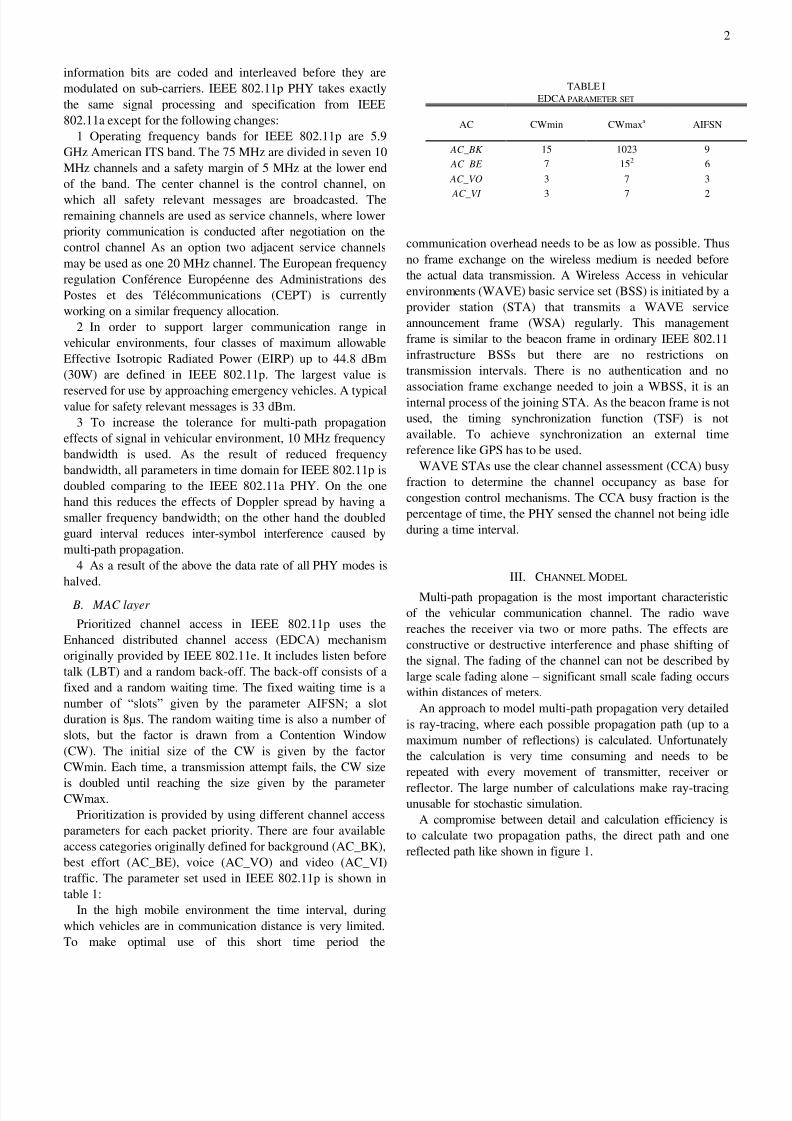
Prioritization is provided by using different channel access
parameters for each packet priority. There are four available
access categories originally defined for background (AC_BK),
best effort (AC_BE), voice (AC_VO) and video (AC_VI)
traffic. The parameter set used in IEEE 802.11p is shown in
table 1:
In the high mobile environment the time interval, during
which vehicles are in communication distance is very limited.
To make optimal use of this short time period the
communication overhead needs to be as low as possible. Thus
no frame exchange on the wireless medium is needed before
the actual data transmission. A Wireless Access in vehicular
environments (WAVE) basic service set (BSS) is initiated by a
provider station (STA) that transmits a WAVE service
announcement frame (WSA) regularly. This management
frame is similar to the beacon frame in ordinary IEEE 802.11
infrastructure BSSs but there are no restrictions on
transmission intervals. There is no authentication and no
association frame exchange needed to join a WBSS, it is aninternal process of the joining STA. As the beacon frame is not
used, the timing synchronization function (TSF) is not
available. To achieve synchronization an external time
reference like GPS has to be used.
WAVE STAs use the clear channel assessment (CCA) busy
fraction to determine the channel occupancy as base for
congestion control mechanisms. The CCA busy fraction is the
percentage of time, the PHY sensed the channel not being idle
during a time interval.
III. CHANNEL MODEL
Multi-path propagation is the most important characteristic
of the vehicular communication channel. The radio wave
reaches the receiver via two or more paths. The effects are
constructive or destructive interference and phase shifting of
the signal. The fading of the channel can not be described by
large scale fading alone – significant small scale fading occurs
within distances of meters.
An approach to model multi-path propagation very detailed
is ray-tracing, where each possible propagation path (up to a
maximum number of reflections) is calculated. Unfortunately
the calculation is very time consuming and needs to be
repeated with every movement of transmitter, receiver or
reflector. The large number of calculations make ray-tracingunusable for stochastic simulation.
A compromise between detail and calculation efficiency is
to calculate two propagation paths, the direct path and one
reflected path like shown in figure 1.
TABLE I
EDCA PARAMETER SET
AC CWmin CWmaxa AIFSN
AC_BK 15 1023 9
AC_BE 7 152 6
AC_VO 3 7 3
AC_VI 3
7 2

8/8/2019 1569014956
http://slidepdf.com/reader/full/1569014956 3/5
3
d
h
d
P
Pt
r
2
2
2
4
c o s21
4
Figure 1 Two-ray channel model
The calculation is conducted for every combination of
transmitter and receiver. A phase shift is applied to the
reflected propagation path, depending on the material of the
reflector. As the road is the main reflector in the vehicular
environment, the reflection coefficient for asphalt is chosen.
Beside the distance between transmitter and receiver, the
wavelength, the reflection coefficient and the antenna height,
the path-loss exponent “Gamma” is a parameter for the path-
loss calculation. A Gamma value of 2.0 represents free space
propagation, a value of 3.5 is a relatively lossy environment
mainly found indoor. Based on the work in [1] the path loss
exponent 2.4 for the scenario evaluated in this paper is
selected.
A detailed description on the channel modeling and error
model used for the simulation can be found in [2].
IV. MOBILITY MODEL
The mobility model emulates a typical highway section. The
scenario is made up by a number of lanes for both directions
with a middle separator of two lanes width. Each vehicle has apreferred speed, depending on its type. The preferred speed is
not necessarily the actual speed – each vehicle maintains a
speed dependant safety distance to its predecessor. While the
safety distance requirement is met, the vehicle accelerates up
to its preferred speed. If accelerating to, or driving at the
preferred speed is not possible, a change to the overtaking lane
is considered. When distance checks to the front and rear view
of both lanes, the current and the target lane, are passed, a lane
change is conducted. When no lane change is possible, the
vehicle de-accelerates until the safety distance requirement is
met again, or the vehicle halts.
Vehicles leave the scenario at the border (different for bothdirections) and new vehicles are inserted on the opposite side.
V. SCENARIO DESCRIPTION
The scenario chosen for the evaluation is the highway
scenario. Four highway lanes, two for each direction, are
divided by a middle separator. The scenario setup is shown in
figure 2. The length of the highway is 5km with up to 40
vehicles. A mixture of different types of vehicles with a
preferred speed between 60km/h and 180km/h are simulated.
Figure 2 Highway scenario
The antenna height of the vehicles is set to 1.65m. The
reflection coefficient of the reflected path in the 2-ray channelmodel is -0.7 (asphalt).
On the physical layer the most robust PHY mode is chosen
(Binary Phase Shift Keying with 50% redundancy, BPSK1/2).
The transmission power is 33dBm (2W). Omni-directional
antennas are used, so no antenna gain is involved. The center
frequency is 5.9GHz with a channel bandwidth of 10MHz.
In the MAC layer, the second-highest access category
(AC_VI, see tabular 1) is chosen for the prioritized channel
access, as the transmitted packets shall be status messages, not
warning messages.
The IEEE 802.11p protocol stack, the channel and mobility
model were implemented in our event-driven stochasticprotocol simulator Wireless Access Radio Protocol 2
(WARP2). The simulator has been used in many publications,
diploma and PhD thesis, as well as in the standardization of
IEEE 802.11e (Quality of Service), IEEE 802.11p (Wireless
access in vehicular environments) and IEEE 802.11s (Mesh
networks). It features a very detailed MAC implementation
and a realistic interference modeling.
VI. SIMULATION RESULTS
Each vehicle in the scenario transmits a so called “Hello-
message” regularly. The “Hello-message” is a 300 byte framecontaining the transmitters MAC_ID timestamp and position
information derived from the onboard GPS. It is transmitted
ten times a second with the most robust PHY-mode BPSK1/2
and a transmission power of 33dbm (2Watt). To collect
information about the neighboring vehicles each car evaluates
all received “Hello-messages”. The information contained in
the “Hello-messages” is collected in the neighborhood table.
Table 1 shows exemplary the contents of the neighborhood
table kept in each receiver: The transmitters MAC_ID, its GPS
position, the table duration and the silent duration. The silent

8/8/2019 1569014956
http://slidepdf.com/reader/full/1569014956 4/5
4
duration is the difference between the actual time and the
timestamp of the last received “Hello-message”. Each time a
“Hello-message” is received from a MAC_ID that is already
included in the neighborhood table, the position and silent
duration entries are updated. When the silent duration is larger
than a preset threshold the tabular entry is considered to be
outdated and is removed from the tabular. The threshold for
this simulation is set to 200ms. As this is twice the time of the
“Hello-message” repetition interval, a single frame loss willnot lead to the removal from the neighborhood list. On the one
hand this setting considers singe frame collisions, when
judging the neighborhood, on the other hand it removes
vehicles from the neighborhood list as fast as possible, to
allow for the evaluation of the upper boundary of the potential
communication duration. The potential communication
duration is the period of time, a vehicle is listed in the
neighborhood table. This value is stored in the column “Table
duration”.
MAC_ID Silent
duration
Table
duration
Relative
x-Position
Relative
y-Position
15 150ms 5s -150m 03 74ms 2s 350m 5
38 25ms 1s 75m 0
Table 1 Neighborhood table
To evaluate the number of neighbor vehicles the number of
entries in all neighborhood tables is recorded. The result of
this evaluation is shown in figure 3. The figure shows the
probability for having the number of n neighboring vehicles in
communication range. The simulation results show that the
average number of potential communication neighbors in this
scenario is approximately four.
Figure 3 Distribution of potential communication neighbor numbers
In addition the duration, a vehicle is listed in the
neighborhood table is analyzed. This is the potential
communication duration of the vehicle with its peer. Figure 4
shows the complementary cumulative distribution function
(CCDF) of the potential communication duration. In 50% of
all occurrences, the maximum potential communication
duration is approximately 1s; in 90% of the occurrences the
upper boundary for the communication time is 5s.
Figure 3 Probability for potential communication duration
VII. CONCLUSION
In this paper, we evaluated the number of potentialcommunication partners and the maximum communication
duration for a vehicular ad-hoc network using IEEE 802.11p
transceivers in a highway scenario. Both distributions will be
used in further studies as input parameters for the planning of a
multi-hop communication route that enables efficient warning
message forwarding in the highway scenario.
REFERENCES
[1] Zhao, X. and Kivinen, J. and Vainikainen, P. and Skog, K., Propagation
characteristics for wideband outdoor mobile communications at 5.3
GHz, IEEE Journal on Selected Areas in Communications, 2002, vol.
20, pages 507-514.[2] Zang, Yunpeng and Stibor, Lothar and Orfanos, Georgios and Guo,
Shumin and Reumerman, Hans-Juergen, An Error Model for Inter-
Vehicle Communications in Highway Scenarios at 5.9GHz, Proceedings
of the Second ACM International Workshop on Performance Evaluation
of Wireless Ad Hoc, Sensor, and Ubiquitous Networks, Oct 2005, pages
49-56.
[3] Katragadda, S., Ganesh Murthy, C.N.S., Ranga Rao, M.S., Mohan
Kumar, S. and Sachin, R. A decentralized location-based channel access
protocol for inter-vehicle communication. In Vehicular Technology
Conference, 2003. VTC 2003-Spring. The 57th IEEE Semiannual
Volume 3, 22-25 April 2003, 1831-1835 vol.3.
[4] Tokuda, K., Akiyama, M. and Fujii, H. DOLPHIN for inter-vehicle
communications system. Intelligent Vehicles Symposium, 2000. IV
2000. Proceedings of the IEEE, 3-5 Oct. 2000, 504-509.
[5] Reichardt, D., Miglietta, M., Moretti, L., Morsink, P. and Schulz, W.
CarTALK 2000: safe and comfortable driving based upon inter-vehicle-communication. Intelligent Vehicle Symposium, 2002. IEEE Volume 2,
17-21 June 2002, 545-550 vol.2. http://www.cartalk2000.net
[6] Franz, W., Eberhardt, R. and Luckenbach T. Fleetnet - internet on the
road. In Proc. of the 8th World Congress on Intelligent Transportation
Systems (ITS’01), 2001. http://www.fleetnet.de
[7] Kim, Y. and Nakagawa, M. R-ALOHA Protocol for SS Inter-Vehicle
Communication Network Using Head Spacing Information. IEICE
Trans. Commun., vol. E79-B, no. 9, September 1996.
[8] Verdone, R. Multi-hop R-Aloha for inter-vehicle communication at
millimeter waves. IEEE Transactions on Vehicular Technology, vol. 46,
no. 4, November 1997.
[9] Borgonovo, F., Capone, A., Cesana, M. and Fratta, L. ADHOC MAC: A
new, flexible and reliable MAC architecture for ad-hoc networks. In

8/8/2019 1569014956
http://slidepdf.com/reader/full/1569014956 5/5
5
Proc. of IEEE Wireless Communications and Networking Conference
(WCNC’03), 2003.
[10] PREVENT: Preventive and active safety; 6th Framework program
integrated project http://www.prevent-ip.org/
[11] Lott, M., Halfmann, R., Schulz, E. and Radimirsch, M. Medium Access
and Radio Resource Management for Ad Hoc Networks based on
UTRA TDD. MobileHOC 2001, CA, USA, October 2001.
[12] Stibor, L. Development and evaluation of an advanced MAC protocol
modeled after IEEE 802.11 including support for Quality of Service in
Multi-Hop Networks at data rates of up to 1Gbps. Diploma Thesis,
Chair of Communication Networks, RWTH Aachen University,Aachen, Germany, 2003.
[13] IEEE Standard for Information technology – Telecommunication and
information exchange between systems – Local and metropolitan area
networks – Specific requirements, Part 11: Wireless Medium Access
Control (MAC) and Physical Layer (PHY) specifications: Amendment
7: Medium Access Control (MAC) Quality of Service (QoS)
Enhancements, IEEE Draft Amendment P802.11e/D11.0, Oct. 2004
[14] Mangold, S., Choi, S., Hiertz, G. R., Klein, O. and Walke, B. Analysis
of IEEE 802.11 for QoS Support in Wireless LANs. IEEE Wireless
Communications, Vol. 10, Dec. 2003, p.p. 2-12.
[15] Mangold, S., Choi, S., May, S. P., Klein, O., Hiertz, G. R., and Stibor,
L. IEEE 802.11e Wireless LAN for Quality of Service. Proceedings of
the European Wireless, Vol. 1, p.p. 32-39, Florence, Italy, Feb. 2002.
[16] Hiertz, G. R., Habetha, J., May, P., Weiß, E., Rajesh, B. and Mangold,
S. A Decentralized Reservation Scheme for IEEE 802.11 Ad Hoc
Networks. The 14th IEEE 2003 International Symposium on Personal,Indoor and Mobile Radio Communications, ISBN 0-7803-7823-7,
Beijing, China, Sep. 2003.
[17] Hiertz, G. R., Zang, Y., Habetha, J. and Sirin, H. Multiband OFDM
Alliance – The next generation of Wireless Personal Area Networks.
Proceedings of the IEEE Sarnoff Symposium 2005, Princeton, New
Jersey, U.S., Apr. 2005.
[18] Ebner, A, Rohling, H., Lott, M. and Halfmann, R. Decentralized slot
synchronization in highly dynamic ad-hoc networks. 5th International
Symposium on Wireless Personal Multimedia Communications WPMC
2002. Honolulu, Hawaii, October 2002.


