Embed Size (px)
Citation preview
8/13/2019 2012727164328081
http://slidepdf.com/reader/full/2012727164328081 1/5
Advanced Temperature Contro ller Ramp and Soak Temperature Contr oller
User Manual
1 Front panel and operation
1:PV display: Indicates the sensor readout, or process value(PV)
2:SV display: Indicates the set value(SV) or output value(%)
3:OUT1: Output indicator, It is synchronized with control output and the power to the load. When it is on, the heater (or cooler)is powered.
This controller is intended to control equipment under normal operating conditions. If failure or malfunction of the controller may lead to abnormal operating conditionsthat may result in personal injury or damage to the equipment or other property, devices (limit or safety controls) or systems alarm or supervisory intended to warnof or protect against failure or malfunction of the controller must be incorporated into and maintained as part of the control system.
4:OUT2: Output 2 is not applicable for this instrument.
5:ALM2: It lights up when AL2 relay is on6:AUX: Auxiliary output indicator, when auxiliary function incorporated and activated, the indicator lights up.
7:AL1: It lights up when AL1 relay is on
9:A/M: Auto/manual control function key/ data shift key
10:Decrement key/Run or STOP the program
11:Increment key/Stop the programkey
T
AUX OUT OUT
ALM ALM
A/M RUN/HOLD STOP
PV
SV
1
2
3
4
5
6
7
8
9 10
11
1.1 Display Status
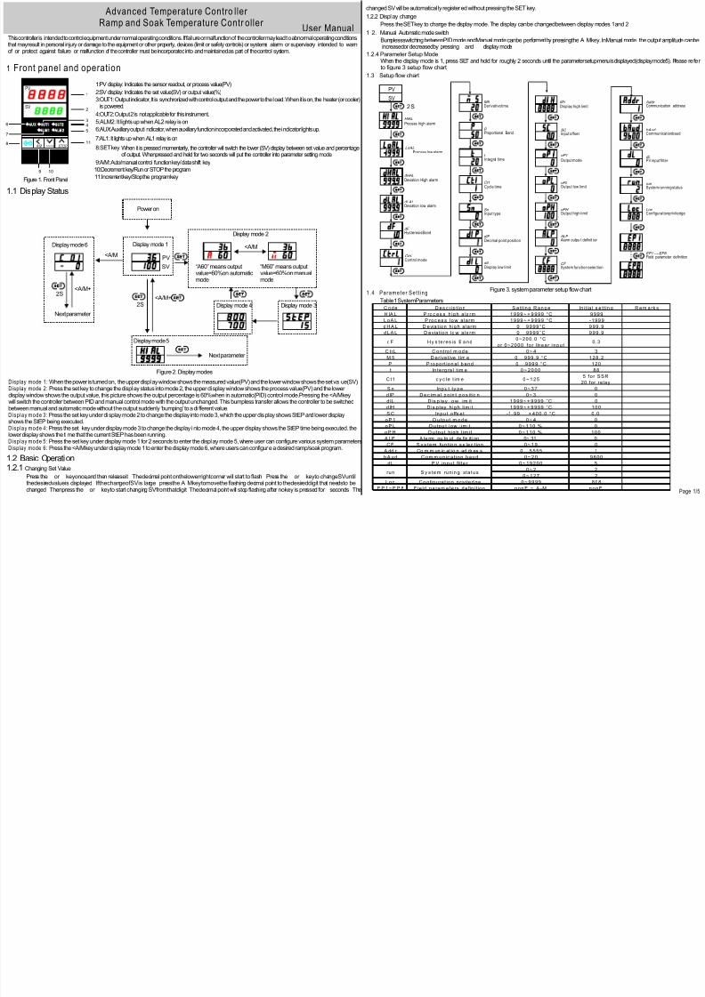
Display mode 1: When the power is turned on, the upper display window shows the measured value(PV) and the lower window shows the set val ue(SV)Display mode 2: Press the set key to change the displ ay status into mode 2, the upper display window shows the process value(PV) and the lowerdisplay window shows the output value, this picture shows the output percentage is 60%when in automatic(PID) control mode.Pressing the <A/Mkeywill switch the controller between PID and manual control mode with the output unchanged. This bumpless transfer allows the controller to be switchedbetween manual and automatic mode without the output suddenly ‘bumping’ to a di fferent value.Display mode 3: Press the set key under display mode 2 to change the display into mode 3, which the upper display shows StEP and lower displayshows the StEP being executed.Display mode 4: Press the set key under display mode 3 to change the display i nto mode 4, the upper display shows the StEP time being executed. thelower display shows the time that the current StEP has been running.Display mode 5: Press the set key under display mode 1 for 2 seconds to enter the display mode 5, where user can configure various system parametersDisplay mode 6: Press the <A/Mkey under display mode 1 to enter the display mode 6, where users can configure a desired ramp/soak program.
Power on
<A/M
“A60” means outputvalue=60%on automaticmode
“M60” means outputvalue=60%on manualmode
PV
SV
Display mode 1
Display mode 2
Display mode 3Display mode 4
T
2S<A/M+ T
Display mode 5
T
Next parameter
T
Display mode 6
T
2S<A/M+
Next parameter
T T
<A/M
Figure 1. Front Panel
Figure 2. Display modes
1.2 Basic Operation1.2.1 Changing Set Value
Press the or keyonce,and then releaseit Thedecimal point onthe lowerrightcorner will start to flash Press the or keyto changeSVuntilthedesiredvalueis displayed IfthechangeofSVis large pressthe A Mkey tomovethe flashing decimal point to thedesireddigit that needsto be
changed Thenpress the or keyto start changing SVfromthatdigit Thedecimal point will stop flashing after nokey is pressed for seconds The
changed SV will be automatical ly registered without pressing the SET key.
1.2.2 Display change
Press the SET key to change the display mode. The display can be changed between display modes 1 and 2
1 2. Manual Automaticmodeswitch
BumplessswitchingbetweenPIDmodeandManual modecanbe performed by pressingthe A Mkey. InManual mode theoutput amplitude canbeincreasedor decreasedby pressing and displaymode
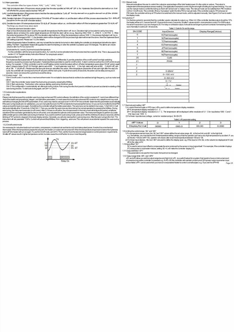
1.2.4 Parameter Setup Mode When the display mode is 1, press SET and hold for roughly 2 seconds until the parameter setup menu is displayed (display mode 5). Please refer
to figure 3 setup flow chart
PV
SV
T 2 S
Process high alarm
Process low alarm
Deviation High alarm
Deviation low alarm
Hysteresis Band
T
T
T
T
T
T
Control mode
T
Input offset
Output mode
T
Output low limit
T
HIAL
LoAL
dHAL
dLAL
dF
CtrL
T
Derivative time
Proportional Band
M5
P SC
oP1
oPL
Output high limitoPH
T
Alarm outpu t definit ionALP
T
System function selectionCF
T
T
Communication addressAddr
Communication baudbAud
T
PV input filter dL
T
T
System running statusrun
Configuration priviledgeLoc
T
T Field parameter definitionEP1 ----EP8
Figure 3. systemparameter setup flow chart
T
T
T
T
Integral time
Cycle time
Input type
Decimal point position
Display low limit
t
Ct1
Sn
dIP
dIL
T
Display high limitdIH
T
T
1.3 Setup flow chart
C ode D es c rip t ion S et t ing R an ge In it ia l s e t t in g R em a rk s
H IA L P roc es s h ig h a la rm 1 999 ~ + 9 999 °C 9 999
L oA L P roc es s lo w a la rm 1 999 ~ + 9 999 °C -199 9
d H A L D evia t ion h ig h a la rm 0 99 99°C 9 99. 9
d LA L D evia t io n lo w a la rm 0 99 99°C 9 99. 9
dF H y s te res is B a nd0~200. 0 °C
or 0~2000 f o r l inear i npu t0. 3
C trL C ont ro l m od e 0~ 4 3
M 5 D eriva t ive t im e 0 999 .9 °C 1 28. 2
P P ro port ion a l b and 0 999 9 °C 120
t In te rg ra l t im e 0 ~ 20 00 88
C t1 c y c le t im e 0~ 1 255 f o r S S R
20 for relay
S n Inp u t ty pe 0~ 3 7 0
dIP D e c im a l p o in t po s it io n 0~ 3 0
dIL D is p la y lo w lim it 1 999 ~ + 9 999 °C 0
dIH D is p lay h ig h lim it 1 999 ~ + 9 999 °C 100
S C Inpu t o ffs e t -1 . 99 + 400 .0 °C 0.0
o P 1 O utp u t m od e 0~ 4 0
o P L O u tpu t low lim it 0 ~ 11 0 % 0
o P H O u tpu t h ig h lim it 0 ~ 11 0 % 100
A LP A la rm ou tp ut de fin iti on 0~ 31 0
C F S y s tem fun t io n s e lec t ion 0~ 1 9 0
A dd r Co m m un ic at io n ad dr es s 0 5 555 1
b A ud C om m un ic a t ion bau d 0~ 2 0 9 600
dL P V in pu t filte r 0 ~ 19 200 5
0~ 2 2
0~ 1 27 2
L oc C o nfig ura t ion p riviled ge 0 ~ 99 99 808
E P 1 ~ E P 8 F ie ld pa ram ete rs d e fin it ion non E ~ A -M n onE
run S y s te m run in g sta tu s
Table 1 SystemParameters
1.4 Parameter Set t i ng
8:SET key:When it is pressed momentarily, the controller will switch the lower (SV) display between set value and percentageof output. Whenpressed and held for two seconds will put the controller into parameter setting mode.
Page 1/5
8/13/2019 2012727164328081
http://slidepdf.com/reader/full/2012727164328081 2/5
changed Thenpress the or keyto start changing SVfromthatdigit Thedecimal point will stop flashing after nokey is pressed for seconds The Page 1/5
1.4.1 Alarmparameters
This controller offers four types of alarm, “HIAL” “ LoAL” “ dHAL” “dLAL”
HIAL: High limit absolute alarm. If the process value is greater than the value specified as “HIAL+dF” (dF is the Hysteresis Band),then the alarmwill turn on. It willturn off when the process value is less than “HIAL-dF”
LoAL: Low limit absolute alarm. If the process value is less than the value specified as “LoAL-dF” then the alarmwill turn on,and the alarmwill turn off if the processvalue is greater than “LoAL+dF”.
dHAL: Deviation high alarm. If the temperature is above “SV+dHAL-dF” the alarmwill turn on, and the alarmwill turn off if the process value is less than “SV+dHAL-dF”
(we will discuss the role of dF in the later section)
dLAL: Deviation low alarm. If the temperature is below “SV-dLAL-dF”,the alarmwill turn on,and the alarmwill turn off if the temperature is greater than “SV-dLAL+dF”
The things you should know about alarm
2)AlarmSuppression feature Sometimes, user may not want the low alarmto be turned on when starting the controller at a temperature below the low alarmsetting. The Alarm Suppression feature will suppress the alarmfromturning on when the controller is powered up (or SV changes). The alarms can only beactivated after the PV has reached SV.
1) Absolute alarmand deviation alarmHigh (or low) limit absolute alarmis set by the specific temperatures that the alarm will be on. Deviation high (or low) alarmis set by how manydegrees above (or below) the control target temperature (SV) that the alarmwill be on.e.g. Assuming HIAL=1000 C , dHAL=5 C, SV=700 C. Whenthe probe temperature (PV) is above 705, the deviation alarmwill be on. When the temperature is above 1000 C, the process high alarmwill be on.Later, when SV changes to 600 C, the deviation alarmwill be changed to 605 but process high alarmwill remain the same. Here the Hysteresis Band(dF) setting is ignored. Please see 1.5.2 for details.
3) Activate the AL1 and AL2 by time instead of temperatureFor the controllers with the ramp and soak function, AL1 and AL2 can be activated when the process reaches a specific time. This is discussed in thesection 3.7 of “Supplementary Instruction Manual” for ramp/soak version”.
1.4.2 Hysteresis Band “dF”
The Hysteresis Band parameter dF is also referred as Dead Band, or Differential. It permits protection of the on/off control f romhigh switchingfrequency caused by process input fluctuation. Hysteresis Band parameter is used for on/off control, 4-alarmcontrol as well as the on/off control at auto
tuning. For example: 1) When controller is set for on/off heating control mode,the output will turn off when temperature goes above SV+dF and on again when it drops to below SV-dF. 2) If the high alarmi s set at 800 C and hysteresis is set for 2 C, the high alarmwill be on at 802 C (ALM1+dF) and off at 798 F (ALM1-dF). Please note that the cycle time can also affect the action. If the temperature passes the dF set point right after the start of a
cycle, the controller will not respond to the dF set point until the next cycle. I f cycle time is set to 20 seconds, the action can be delay as long as 20seconds. Users can reduce the cycle time to avoid the delay.
1.4.3 Control mode“ CtrlCtrl=0 On/off control. It works like a mechanical thermostat. It is suitable for devices that do not like to be switched at high frequency, such as motor and
valves
Ctrl=1 Gets the controller ready to start the Auto tuning process by pressing the A/Mkey. Ctrl=2 Start auto tuning. The function is the same as starting auto tuning fromfront panel. Ctrl=3 This configuration is automatically set after auto tuning is done. Autotuning fromthe front panel is inhibited to prevent accidental re-starting of the
auto tuning process. To start auto tuning again, set Ctrl=1 or Ctrl=2.
1.5 Control action explanations
1.5.1 PID
Please note that because this controller uses fuzzy logic enhanced PID control software, the definition of the control constants (P, I and d) are different thanthat of the traditi onal proportional, integral , and derivative parameters. In most cases the fuzzy logic enhanced PID control is very adaptive and may workwell without changing the initi al PID parameters. If not, users may need to use auto-tune function to let the controller determine the parameters automatically.If the auto tuning results are not satisfactory, you can manually fine-tune the PID constants for improved performance. Or you can try to modify the init ial PIDvalues and performauto tune again. Sometimes the controller will get the better parameters. The auto-tune can be started in two ways. 1) Set Ctrl=2. It willstart automatically after 10 seconds. 2) Set Ctrl=1. Then you can start the auto-tune any time during the normal operation by pressing the A/Mkey. Duringauto tuning, the instrument executes on-off control. After 2-3 times on-off action, the microprocessor in the instrument will analyze the period, amplitude,waveformof the oscillation generated by the on-off control, and calculate the optimal control parameter value. The instrument begins to performaccurateartificial intelligence control after auto tuning is finished. If you want to exit fromauto tuning mode, press and hold the (A/M) key for about 2 seconds until theblinking of "At" symbol is stopped in the lower display window. Generally, you will only need perform auto tuning once. After the auto tuning is finished. Theinstrument will set parameter “Ctrl”to 3, which will prevent the(A/M)key from triggering auto-tune.This will prevent an accidental repeat of the auto-tuningprocess.
1.5.2 On/off control mode
It is necessary for inductive loads such as motors, compressors, or solenoid valves that do not li ke to take pulsed power. It works li ke a mechanicalthermostat. When the temperature passes the set point, the heater (or cooler) will be turned off. When the temperature drops back to below the hysteresisband (dF) the heater will turn on again.To use the On/off mode, set Ctrl=0. Then, set the Hy to the desi red range based on control precision requirements.Smaller dF values result in t ighter temperature control, but also cause the on/off action to occur more frequently.
1.5.3. Manual mode Manual mode allows the user to control the output as a percentage of the total heater power. It is like a dial on a stove. The output is
independent of the temperature sensor reading. One application example is control ling the strength of boiling during beer brewing. You canuse the manual mode to control the boil ing so that it wil l not boil over to make a mess. The manual mode can be switched from PID mode butnot fromOn/off mode. This controller offers a “bumpless” switch fromthe PID to manual mode. If the controller outputs 75%of power atPID mode, the controller will stay at 75%when it is switched to the manual mode, until it is adjusted manually. See Figure 2 for how to switchthe display mode.
1.6 Cycle time “t” It is the time period (in seconds) that the controller uses to calculate its output. e.g. When t=2, if the controller decides output should be 10%,
the heater will be on 0.2 second and off 1.8 seconds for every 2 seconds. Smaller t values result in more precision control. For SSR output,it is set at 5 seconds or you can change to 2S. For relay or contractor output, it should be set longer to prevent contacts f romwearing out toosoon.Normally it is set to 20~ 40 seconds.
SN CODE
0
1
3
4
5
6
7
20
21
Input Device
K(Thermocouple)
S(Thermoucouple)
T(Thermocouple)
E(Thermocouple)
J(Thermocouple)
B(Thermocouple)
N(Thermocouple)
Cu50
Pt100
Display Range(Celcius)
- 5 0 ~ + 1 3 0 0- 5 0 ~ + 1 7 0 0- 2 0 0 ~ + 3 5 00 ~ + 8 0 00 ~ + 1 0 0 00 ~ + 1 8 0 00 ~ + 1 3 0 0- 5 0 ~ + 1 5 0- 2 0 0 ~ + 6 0 0
2
2
2
2
3 03 13 23 33 43 53 63 7
0 ~ 8 0 Ω0 ~ 4 0 0 Ω0~20mV
0~100 mV
0~60 mV
0~1V0 . 2 ~ 1 V4 - 2 0 mA w 5 0 Ω Resistor
V4 ~ 2 0 mA w 2 5 0 Ω Resistor
0 - 5 V- 2 0 m A ~ + 2 0 m A
- 1 0 0 m A ~ + 1 0 0 m A- 5 V ~ + 5 V
- 1 9 9 9 ~ + 9 9 9 9 D e f i n e d b y u s e rw i t h d I L a n d d I H
1.7 Decimal point setting “dIP” 1) In case of thermocouple or RTD input, dP is used to define temperature display resolution. dP=0, temperature display resolution is 1 C dP=1, temperature display resolution is 0.1 C . The temperature will be displayed at the resolution of 0.1 C for input below 1000 C and 1
C for input over 1000 C. 2) For linear input devices (voltage, current or resistance input, Sn=26-37)
Table 3. dP parameter setting
dIP Value
Display format 0000 000.0 00.00 0.000
0 1 2 3
1.9 Limiting the control range, “dIL” and “dIH”1) For temperature sensor input, the “dIL”and “dIH” values define the set value range. dIL is the low limit, and dIH is the high limit.
e.g. Sometimes, you may want to limit the temperature setting range so that the operator can’t set a very high temperature by accident. If you set the dIL=100 and dIH =130, operator will only be able to set the temperature between 100 and 130. 2) For linear input devices, “dIL”and “dIH” are used to define the display span. e.g. If the input is 0-5V. dIL is the value to be displayed at 0V and dIH is the value at 5V.1.10 Input offset “SC”
SC is used to set an input offset to compensate the error produced by the sensor or input signal itself . For example, if the controller displays0 0
5 C when probe is in ice/water mixture, setting SC=-5, will make the controller display 0 C.1.11 Output definition “oP1”
This parameter is not used for this model. It should not be changed.
1.12 Output range limits “oPL” and “oPH”oPL and oPH allow you set the output range low and high l imit. oPL is a useful feature for a system that needs to have a minimumamount
of power as long as the controller is powered. e.g. If oPL=20, the controller will maintain a minimumof 20%power output even when input
sensor failed oPH canbeusedwhenyouhaveanoverpoweredheater tocontrol asmallsubject e g Ifyouset theoPH=50
Table 2. Code for Sn and its range.
Page 2/5

8/13/2019 2012727164328081
http://slidepdf.com/reader/full/2012727164328081 3/5
e.g. If you set the oPH=50, the 5000 watt heater will be used as 2500Wheater (50%) even when the PID wants to send 100%output.
1.13 Alarmoutput definiti on “ALP” Parameter “ALP” may be configured in the range of 0 to 31. It is used to define which alarms ( “HIAL” “LoAL” “dHAL” and “dLAL” is output to AL1 or AL2. Its function is determined by the following formula ALP=AX1+BX2+CX4+DX8+EX16 If A=0, then AL2 is activated when Process high alarmoccurs; If A=1, then AL1 is activated when Process high alarmoccurs
If B=0, then AL2 is activated when Process low alarmoccurs; If B=1, then AL1 is activated when Process low alarmoccursIf C=0, then AL2 is activated when Deviation high alarmoccurs; If C=1, then AL1 is activated when Deviation high alarm occursIf D=0, then AL2 is activated when Deviation low alarmoccurs If D=1, then AL1 is activated when Deviation low alarmoccursIf E=0, then alarm types, such as “HIAL” and “LoAL” will be displayed alternati vely in the lower display window when the alarms are on.This makes it easier to determine which alarms are on. If E=1, the alarmwill not be displayed in the l ower display window (except for “orAL”)Generally this setting is used when the alarm output is used for control purposes. For example , in order to activate AL1 when a Process highalarmoccurs, trigger AL2 by a Process low alarm, Deviation high alarm, or Deviation low alarm, and not show the alarm type in the lower displaywindow, set A=1, B=0, C=0, D=0, and E=1. Parameter “ALP” should be configured to: ALP=1X1+0X2+0X4+0X8+1X16=17 this is the factorydefault setting)Note: Unlike controllers that can be set to only one alarmtype (either absolute or deviation but not both at same time), this controllerallows both alarmtypes to functi on simultaneously. If you only want one alarmtype to function, set the other alarm type parameters to maximumorminimum(HIAL, dHAL and dLAL to 9999, LoAL to -1999) to stop its function.
1.14 Systemfunction selection “CF”
Parameter “CF” is used to set the heating or cooling, alarmsuppression and power restriction function. Its value is determined by the following formula: CF=AX1+BX2+CX16
A=0, reverse action control mode for heating control. A=1, direct action control mode for cooling control.B=0, without alarmsuppressing when turned on or when set point changes.B=1, alarmsuppressing at power up or set point changes.C=0, without power restricted functionC=1, with power restricted functionThe factory setting is A=0, B=0, C=0 (heating, without alarm suppression, without power restricted function, Therefore CF=0X1+0X2+0x16=0
1.15 Input digital filter “dL”If measurement input fluctuates due to noise, then a digital filter can be used to smooth the input. “dL” may be configured in the range of 0 to 20.
Stronger filtering increases the stability of the readout display, but causes more delay in the response to change in temperature. dL=0 disables the filter.
1.16 Manual and Automatic Mode Select ion “run” Parameter run is for selecting automatic or manual control mode. run=0, manual control mode
run=1, automatic control mode (either PID or On/off control) run=2, automatic control mode, in this state manual operation is prohibited This parameter functions differently for controllers with the ramp/soak function (see supplemental manual for details).
1.17 Lock up the settings, f ield parameter “EP” and parameter “LocK” To prevent the operator fromchanging the settings by accident, you can lock the parameter settings after initial setup. You can select which
parameter can be viewed or changed by assigning one of the field parameters to i t. Up to 8 parameters can be assigned into field parameterEP1-EP8. The field parameter can be set to any parameter listed in Table 2, except parameter EP itself. When LocK is set to 0, 1, 2, and so on,only parameters or setting values of programdefined in an EP can be displayed. This function can speed up parameter modification and preventcritical parameters (like input, output parameters) frombeing modified. If the number of field parameters is less than 8, then define the first unused
parameter as none. For example, if only ALM1 and ALM2 need to be modified by field operators, the parameter EP can be set as following: LocK=0, EP1=HIAL, EP2=LoAL, EP3=nonE. In this case, the controller will ignore the field parameters fromEP4 to EP8. If field parameters are not
needed after the instrument is initially adjusted, simply set EP1 to nonE. Lock code 0, 1 and 2 will give the operator limited privileges to change some of the parameters that can be viewed. Table 5 shows the privileges associated with each lock code.
Lock Value SV adjustment EP1-EP8 adjustment Other parameters
0
12
3 and UP
808
yes
yes
No
No
yes
Noyes
No
Locked
LockedLocked
Locked
Unlocked
Quick Guide for Advanced Temperature Controller 1. Wiring 1) Power to the control ler. Connect the 90-260VAC power to terminal s 1 and 2. 2) Control output connection. Connect terminals 3 and 5 for SSR Drive output, 3 for negative and 5 for positive. 3) Sensor connection. For thermocouples, connect the positive wire to terminal 10, the negative to terminal 11.
For a three-wire RTD with standard DIN color code, connect the two red wires to terminals 10 and 11, and connect the white wire to terminal 9.For a two-wire RTD, connect the wires to terminals 10 and 11, Then, jump a wire between terminals 9 and 10.
2. Set sensor type
Set Sn to 0 for a K type thermocouple (default), 5 for a J type thermocouple, and 21 for a Pt100 RTD.
3. Switching between automatic and manual mode
Set run=0 to active manual mode. Press the A/Mkey to switch between automatic and manual mode.
4. Setting the controller for cooling control. For cooling control, set CF=1, the initial setting is CF=0 for heating control
Setting target temperature SV Press the or key once, and then release it The decimal point on the lower right corner will start to flash Press the or key to change SV until the desired value is displayed The decimal point will stop flashing after no key is pressed for seconds You can press
the A/M key to move the flashing decimal point to the desired digit that needs to change Then press the or key to change SV starting from that digit6. Auto-tune You can use the auto-tune function to determine the PID constants automatically. There are two ways to start auto-tuning: 1) Set Ctrl=2. It will start automatically after 10 seconds. 2) Set Ctrl=1. Then during the normal operation, press the A/Mkey to start the auto-tune. The instrument will performaccurate artificial intelligence
control after auto tuning is finished.
7.On/off mode Set Ctrl=0 to active the on/off control mode. Set the Hysteresis Band parameter dF to be a desired value.
8. Error Message and trouble shooting
8.1 Display orALThis is an input error message. The possible reasons are: the sensor is not connected correctly; the input setting is wrong type;or the sensor is defective
In this case, the instrument terminates its control function automatically, and the output value is fixed according to the parameter oPL. If this happens when usingthermocouple sensor, you can short terminal 10 and 11 with a copper wire. If the display shows ambient temperature, the thermocouple is defective.If it still displays orAL, check the input setting, Sn, to make sure it is set to the right thermocouple type. If the Sn setting is correct, the controller is defective.For RTD sensors, check the input setting first because most controllers are shipped with the input set for thermocouples. Then check the wiring. The twored wires should be connected to terminals 10 and 11. The clear wire should be connected to terminal 9.
8.2 No heatingWhen the controller output is set for relay output, the “O U T” LEDis synchronized with output relay. If heat is not output when it is supposed to, check the OUTLED first. If it is not li t, the controller parameter settings are wrong. If it is on, check the external switching device (if the relay is pulled-in, or the SSR’s red LED ison). If the external switching device is on, then the problemis either the external switching device output, its wiring, or the heater. If the external switching deviceis not on, then the problemis either the controller output, or the external switch device.8.3 Poor AccuracyPlease make sure calibration i s done by immersing the probe in liquid.Comparing the reference in air is not recommended because response time of the sensor depends on its mass. Some of our sensors have response time> minutes in the air. When the error is larger than C, the most commonproblemis an improper connection between the thermocouple and the controller. The thermocouple needs to be connected directly to the controller unless a thermocouple connector and extension wire is used. Copper wire or a thermocouple extension wire with the wrong polarity connected on thethermocouple will cause the reading to drif t more than 5 C.
8.4 On on/off mode Although hysteresis is set to 0.3, the unit is running 5 degrees above and below. If the dF is very small and temperature changes very quickly, users
will need to consider the delay of the cycle ti me (the parameter t). For example, if cycle t ime is 20 seconds, when the temperature passes the SV+dF after the beginning of a 20 seconds cycle, the relay will not act unti l the start of the next cycle 20 seconds later. Users may change the cycle time to asmaller value, such as 2 seconds, to get better precision control.
Supplementary Instruction ManualFor the Ramp/Soak option of Programmable Controller
Version 6.58This is a supplementary manual for the Ramp/Soak controller. It is only for operating the programmable steps (ramp and soak steps) functions. The mainmanual for the Ramp/Soak is the same as the advanced temperature controller. It covers all the regular set up and operation instructions. The Ramp andSoak series programmable controllers with the ramp/soak option are designed for applications where it is desirable to have the set point automaticallyadjust itself over time.
1. Features 50 steps of programcontrol for ramping and soaking process.High flexibility in programand operation. It has programmable/maneuverable commands
such as jump (for loops), run, hold and stop.The programcan even be modified while it is running.The programcan also control the two relays that areused for alarms. This feature can be used to notify the operator of the stage of the operation, or to signal other equipment. The safety start and readyfunction may allows the programto run more efficiently. 6 power-off/power-on event handling (see 3.10) modes can be selected. This can prevent theprogramcontrol frombeing adversely affected by unexpected power interruptions.
2. Terms and Functions Program StEP: The value of the programStEP can range from1 to 50. The current StEP is the programStEP being executed. StEP temperature, CXX: The StEP temperature is the set temperature at the beginning of the step XX (where XX can be any value from 01 to 50). StEP time, tXX: The StEP time is the ramping time from the current step temperature to the next step temperature. The unit is in minutes and the
available value range is from1 to 9999. Running time: The running time is the time that the current StEP has been running. When the running time reaches the StEP time,the programwil l jump to the next StEP automatically. Jump: The programcan jump to any other steps in the range of 1 to 30 automatically as you programmed in the program StEP. It can also be used to perform cycle control. If StEP number is modified, the programwill also jump. Furthermore if the programStEP reaches and finishes the 50th
StEP, the program will jump back to the first StEP and run automatically. Run : When the programis in the “running”status, the timer counts down, and the set point value changes according to the preset ramp curve. Hold: When the programis in the “hold”status, the temperature is stil l controlled, but the timer is paused so the current set point remains. Stop: When the stop operation is activated, the program, timer, and output control will stop, and the running time and event output switch will reset. If
the “run” operation is activated while the instrument is in the “stop”status, the programwill start-up and run from the StEP 1. Power interrupt: It means the power has turned off or an unexpected power failure has occurred during running status. 6 handling modes are
available to the user. Event output: Event output can be programmed in to the controller. It can trigger two alarmrelays to make external equipment operate with interlock. Safety start: If the difference between the PV and SV is larger than the deviation alarmsetting at the beginning of a step (or when powered up), the controller will adjust the PV until the alarmis turned off before the timer starts. See 3.10 for example.
Page 3/5
8/13/2019 2012727164328081
http://slidepdf.com/reader/full/2012727164328081 4/5
3. Programming3.1 ProgramSetup Press the A/Mkey to bring the instrument into the programsetup mode;the instrument will display the temperature set point of the current StEP
indicated by “C” in the upper display followed by the StEP number). Use theA/Mkey to choose which digit to edit (indicated by the flashing decimalpoint). After adjusting the temperature set point (–1999 to +9999), press theSET key once again, and the current StEP’s ramping time will be displayed
( “t” in the upper display). In each programStEP, the temperature and the time is displayed in turn. Hold down the A/Mkey and press V to go back to
the previous parameter. Hold A/Mand press SET to exit programsetup mode. Modifying programsteps while a programis running is permitted. Seesection 4 for a programming example. Note: the above operation is inhibited if the program setup function is locked(refer to . for the introductionof the LocK parameter
3.2 ProgramRamp To programa ramp, you need to set the start temperature CXX, the end temperature CXX+1, and the time duration tXX. For example, at step 3, if you want the controller to take 60 minutes to ramp up from200 to 300 degrees, set C03=200, C04=300, t03=60. Note: Unless the deviation alarms
are set to a narrow range, the ramping time decides when the programis going to the next step. Once the ramping time is finished the current step,the controller will execute the next step regardless if the temperature reaches the target temperature. Therefore, the ramp speed should be alwayslower than the maximumspeed that the oven can offer at the full power. In other words, the ramping time should be longer than the minimumtimeneeded for oven to jump fromC03 to C04 at full power. If the ramping time is shorter than that, the time programmed for the next step will not befulfil led. When programa temperature ramps down, you need to consider the speed of natural cool ing (or forced air cooling) for the same reason.
If the maximumspeed of the systemis unknown or varies with environmental conditions, users should use the “safety start” function to ensure thatthe temperature and time during ramping and soaking are kept within a reasonable range required by the process. This is done by setting the
deviation alarm close to the SV. At the beginning of a step, the timer will not start until PV is larger than SV-dLAL+dF and smaller than SV+dHAL-dF.e. g. Set dHAL=30, dLAL=20, dF=5 and SV=100. At the beginning of the step, if the temperature is below 85 (SV-dLAL+dF=85) degrees, or above 125
SV dHAL-dF )degrees,the controller will stop the timer to wait until the temperature is above than 85 degrees or below than 125degrees before continuing. Please note that the dF value should be smaller than both dHAL and dLAL, Otherwise the controller will not start the next steps.
3.3 ProgramSoak The soak can be considered as a special case of ramping. It is a ramp with a zero degree slope. To programa soak, you need to set the start and the end temperature to be the same (CXX=CXX+1), e.g. At step 3, if you want the controller to soak the parts at 200 degrees for 60 minutes, set C03=C04=300,
t03=60. Note: The StEP time is not how long the controller will stay at the set temperature for the current step. It is how long the controller will take from the current step temperature set point to the next step temperature set point. These two concepts are very different.3.4 ProgramHold When the programreaches a StEP where the StEP time is set to zero, or when a jumping StEP transitions to another jumping StEP, the programwill be set
to “hold” status You can also manually activate hold status by pressing the V key for about 2 seconds until “HoLd” appears in the lower display window.
3.5 ProgramStop When the programreaches a StEP where the StEP time is set to -121 the controller will stop running The StEP number is reset to 1 the
event output is cleared,and the control output is turned off.You can also manually execute the stop operation by pressing and holding thekey for roughly 2 seconds until the lower display window displays “StoP”.
3.6 Run ProgramIn order to continue the programwhen the controller is in “hold” mode (or restart it from“stop”mode) lower window displays “run”.When a programisrunning,
3.7 StEP Time/Command Parameter When tXX is between 1 and 9999 (min), it is used to set the ramp and soak time. When it is set to zero or a negative number, it is used for executing other commands. tXX=0 The instrument is put in hold mode on StEP number XX until manually released by the operator. tXX=-1 to -240 represents an operation command such as run, hold, stop,jump and event output. The number is calculated according to the equation tXX = -(A*30+B). “B”is the number (ranging from1 to 30) of the next step for the programto jump to and “A” is the event that is triggered: A=0 no effect (for jump function only)
A=1 switch on AL2 A=2 switch on AL1 A=3 switch on AL1 and AL2 A=4 Stop the instrument(B must be set to 1 when A=4) A=5 switch off AL2 A=6 switch off AL2 A=7 switch off AL1 and AL2Examples
Jump from StEP4 to StEP5 and switch on AL2Time setup is t04=-(1x30+5)=-35
Jump from StEP6 to StEP1 and switch off AL2.Time setup is t06=-(5x30+1)=-151
Stop programat StEP8Time setup is t08=-(4x30+1)=-121The controller does not let a jump command jump to itself(for example t06=-6) because the Hold status would never be released
3.8Sometimes it is convenient to jump directly to a particular StEP and execute from there If the programis stil l in the middle of the
4th StEP and you wish to finish it in advance and execute the 5th StEP -the StEP modification feature will meet your need The Ramp and Ramp series controller can start the program from any one of its steps Press the SET key(briefly)to display the StEP number
Press the V keys to change it The StEP number increases or decreases automatically as the program executes If the StEPnumber is manually changed the running time will be cleared to and the program will begin with the new StEP If the StEPnumber is not changed pressing the SET key will not affect the operation of the program
Displaying and modifying the running StEP number (StEP) of the program
3.9 Multiple Curves The flexible programming format of the Ramp & Soak controller can be used to store and recall multiple programmed curves. If a temperature curve
require all 50 steps, the unused steps can be used to store another program. Several different curves can be stored and executed individually, asdoesn’tlong as there are not more than 50 steps total (including necessary controls steps). For example, when a process curve only needs nine program
steps, it i s possibleto store three such process curves in the inst rument. Simply change the StEP number to initiate a di fferent curve. Suppose 8 stepsrepresent three groupsof process parameters. They are separately arranged on StEP2-StEP9,StEP10-StEP17, StEP18-StEP25. The step time of step 1can be set as follows to choose the desired program:
T01=-2 Execute the programof curve 1 (StEP2-StEP9)T01=-10 Execute the programof curve 2 (StEP10-StEP17)T01=-18 Execute the programof curve 3 (StEP18-StEP25)You can also choose the curves by manually setting the value of StEP before the programstarts. For example, if curve 2 is needed in the current process,then set the value of StEP to 10.
3.10 Control Mode Parameter run The function of the run parameter is defined differently in the ramp and Soak controller than it is for the controller without the ramp/soak option. Its
operation is determined according to the equation run = AX1+BX8 Where “A” is used to select one of 4 power outage/startup event handing modes, and “B” is used to select Safety Start and PV preparation function
Power Outage/Startup Modes: A=0: When the instrument is turned on, the programwill simultaneously jump to 29th programsegment and clear event output status. This mode is suitabl for applications in which power failure is not allowed at any time. The user may do error handling in segment 29, such as switching on the event output to trigger an alarm.
A=1: If there is no deviation alarmat power up, the programwill continue running fromthe original break point and the event output state remains.Otherwise, the programwil l jump to the 29th segment and clear event output status.
A=2: After power is turned on, it will continue the programfrom the original break point, and the event output state will remain. This mode is suitable for the applications in which power failure does not affect production (default setting). A=3: After power is turned on, controller goes to Stop status A=4: After power is turned on, controller goes to Hold status, the controllers will goes to Stop status if the controller at Stop mode before power failure.
Safety Start and PV Preparation funct ions:B=0, without and PV preparation function, Programis executed as planned. This mode guarantees constant running time of the programbut it can’t guarantee the integrity of the whole curve.B=1, with the function of Safety Start and without the function PV preparationB=2, with the function of PV preparation and without the function of Safety StartB=3, with the function of Safety Start and PV preparation
Abo ut and PV Prep ara ti onSafety Start Function
At the first step of program, when the ambient temperature is differ fromthe C01(Set point of first step), the controller will automatically adjust therunning time to make the expected set point the same as the current PV.For example, in a systemwhere the programconfigured from 25C to 625C within 600 minutes at the first step, but after the power on in the system,the process value is already at 100C which is higher than the original setpoint 25C for first step, in this case, the controller will automatically adjustthe running time to 75 minutes and run the program. Please noted that Safety Start function only applicable for 1st step of a program
PV Preparation FunctionIn a systemwhere the ambient temperature is differ from the Set point of executed steps, the controller will adjust the PV to SV and maintain theintegrity of the program.For example, in a heating step from100C to 600C, the systemsuffers power off when temperature at 125C. and when power comes back , the PVof the systemis actually at 105C, the controller will automatically adjust the process value to 125C where the power failed point and without increasethe running time of the system. after process value reaches 125C, the programgoes on as planned before.
Safety Start
Safety Start
3.11 Privilege for parameter set LocK For ramp & soak controllers with ramp/soak option, the LocK has slightly different functions. The table 1 shows the privilege of each lock code. Table 1. LocK parameter
LocK value EP1-8 Adjustment ProgramAdjustment Step selectionwhen running
0
1
2
3 and UP
808(default setting)
Yes
Yes
Yes
No
Yes
Yes
No
No
No
Yes
Yes
Yes
No
No
Yes
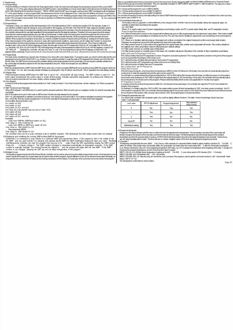
4. Programming Example Programs in the Ramp & Soak controller have a uniformformat of temperature-time-temperature. The temperature set point of the current step will
linearly change to the set point of the next step over the time interval of the two steps. The first temperature set point should always be the ambient temperature at which the process starts to ramp up. DO NOT set the first temperature set point to the target temperature (see example 1 below) if you are not using the safety-start function. The time units are in minutes. Negative values of the time interval represent programcommands.4.1 Example 1 The following example holds the oven at 800 C for 2 hours. In this example, it is assumed that the heater is able to heat the oven from25 C to 800 C within 30 minutes. If the heater does not have this ability, the soak section can begin when the oven is below 800 C after the 30 minutes ramping time is up. Please note that the value of C is the beginning temperature of the step. e.g. C01 is always the temperature at the beginning of the step 1. Usually C01
should be the ambient temperature, and t01 is the time fromstep1 to step2.StEP1: C01=25, t01=30 Start linear temperature heating up from25 C to 800 C, over a time period of 30 minutes (25.8 C /minute).StEP2: C02=800, t02=120 Maintain 800 C for 120 minutes.StEP3: C03=800, t03=-121 Stop the programand let the oven cool down.The equat ion used to get the command number is -(30 * Command# + NextStep) =-(30*4+1)=-121.The temperature control block is shown below.
>
Page 4/5

8/13/2019 2012727164328081
http://slidepdf.com/reader/full/2012727164328081 5/5
1.Bring Up
2.Constant Temp
3.Natural Cooling
Temp 0C
Time(Min)30 150
800
Figure 1. Holding oven at 800 for 2 hours0C
25
4.2 Example 2The following example includes 6 steps: linear temperature heating, maintaining a constant temperature, linear temperature cooling, jump cycling,
0ready, hold and event output. In the fol lowing example, it is assumed that the deviation high alarmdHAL=dLAL= 5 C and dF=0.
StEP1: C01=100, t01=30 Start linear temperature heating up from100 to 400 , over a time period of 30 minutes (10 /minute).0StEP2: C02=400, t02=60 Maintain 400C for 60 minutes.
0 0StEP3: C03=400, t03=120 Reduce the temperature at a rate of |C04-C03|/ t03 = 2C /minute for 120 minutes. This will bring it down to 160 C.StEP4: C04=160, t04=-65 Alarm1 is triggered, and the programjumps toStEP5: The command number for turning alarm 1 on is “2” The equation used to get the command number is-(30*Command#+Next Step)=-(30*2+5)=-65StEP5: C05=160, t05=0 Atime value of zero puts the programin a Hold state. Arun operation executed by the user is needed for the programto continue to StEP6.StEP6: C06=100, t06=-181 Alarm1 is switched off (unless it is also being triggered by an alarmcondition outside the program), and the programjumps to
StEP1 to start fromthe beginning. The command for switching Alarm1 off is “6”,so t06=-(30*6+1)=-1810
StEP1: C01=100, t01=30 Since the temperature is still at 160C, the programwill pause until the controller can bring the temperature within the alarm0
range of the new set point. Since the deviation high alarm is set to 5C, the programwill resume (from the beginning) as soon as the temperature0
drops below SV+dHAL-dF=105 C.The temperature control block is shown below.
0 0 0
C C C
1.Bring up
2.Constant temp
3.Cool down
4.Jump section alarm1 on
5.Hold
6.Jump section alarm 1 off
Ready sectionno timing
Circle fromselection
Alarmoff
Alarmon
Alarmoff Temp 0C
Time(Min)Figure 2. Ramp/Soak Example 2
5.Quick list of the New Key Functions for the Ramp/Soak Model The following list contains a brief description of each key function for when the controller is in basic operation mode.1)Mode Key(SET)
When pressed momentarily PV display shows the current step that the program is processing When pressed again the PV display showsthe set time length of the current step The SV display shows how long the current step has run in minutes Press again to have the
display return to the basic display mode The PV shows the process temperature and SV can either show the set temperature or the statusof the controller(Stopped,Running,or on Hold).Pressing and holding the mode key for two seconds will put the controller into parameter settingmode just like the controllers without the ramp/soak option.
2)Auto/Manual function key(A/M) Press this key to have the controller enter step setting mode in order to set the time temperature and action of each step.3)Decrement key V Press and hold this key for two seconds to start the processing Press and hold again to hold the processing.4)Increment key Press and hold this key for two seconds to stop the processing of the program
Table 2. Summary of New Key Functions
To start the processing Press V for 2 seconds
To stop the processing PressV
for two seconds
Press V for 2 secondsTo hold the processing
Check current step
Check run time of current step
Go to Step X
To programthe steps
Press SET briefly twice
Press SET briefly
Press SET briefly, Then use V orV
to go to step
Press A/Mkey to enter programmingmode. Then, SET key to go to next step.
7. 7.1What is the di f ference between “Hold” and “Stop” . Hold does not stop heating,It holds the temperature at the current setting,( or at oPL,see 3.10 for details), “Stop” will stop heating.
Frequent ly asked quest ions
If you Hold theprogram(V key) and start Run (V key) again, it will start fromthe step that was put into hold.However,if you Stop the program( )and start Run(key)again,it will start fromstep1.
VkeyV
7.2 How do I run this controller as a regular controller without the ramp/soak function?
Here are two methods.1)Program a very long step. If you didn’t use up all the steps for programming,you can use one of the unused steps for that. For example,assumingstep 10 and 11 are unused, set C10=100,C11=10 and t10=9999,This sets Step 10 to control the temperature at 100 degrees for 9999 minutes.Tobegin the program, start Run(V key),press SET once to display StEP,use to go to StEP 10. Press SET twice.The controller will run just like regular controller with PV displayed on top and SV in the bottom.You don’t have to do this every time the controller powers up(assuming the A-Mparameter has not changed from default).It will remain running StEP 10 until 9999 minutes (7 days) runs out,or until you reset it for another application
>
2) Put the programon hold mode. This can be done either by manually pressing the Hold button at the desired temperature, or by programming a hold step (by setting tXX=0).7.3 I just want to run the oven at 800 degrees for 120 minutes.
When I set C01=800, t01=120, the controller SV first displays 800, then it starts dropping with time. Did I do something wrong?
This is the most common mistake first time users make. Since this is a ramp controller, not a step controller, the time t01 (or tXX) is not the time that controller will stay at C01 (or CXX), it is the ramping time that controller will take fromtemperature C01 to C02. To hold the temperature constant for 120 minutes, you need to set two steps at the same temperature, or a 0 degree ramp (C02=C03=800 in this case). Then, set the ramping time for 120 minutes. Please see example 1.
Alarm1
100
160
400
30 90 210
V


