Embed Size (px)
Citation preview

7/28/2019 29_3_085
http://slidepdf.com/reader/full/293085 1/7
Distortion-Induced Cracking During Transit
W. M. KIM RODDIS
1. INTRODUCTION
During the last twenty years, there has been a growing
wareness of distortion-induced cracking in bridges.
Comparable interest in this behavior has not been generated
within the building community. Distortion-induced fatigue
racking is indeed a more common problem in bridges,
rising from cyclic distortions not only during handling and
hipping but also during service. Bridge service conditions
re much more likely to induce cyclic distortions than
uilding service conditions. However, handling and shipping
onditions are similar for both building and bridge
omponents. It would therefore be beneficial if the topic of
distortion-induced cyclic stress as a possible cause of fatigue
racking during shipment were more widely understood in the
teel industry. This paper reviews the characteristics of
distortion-induced cracking as seen in bridges, presents a
detailed example of cracking in building trusses due to cyclic
distortions during transit, summarizes the conditions that lead
o this type of cracking during shipment, discusses the effect
f cracking on structural performance, and provides
ecommendations for prevention of this type of damage.
2. DISTORTION-INDUCED CRACKING
Different kinds of steel structures and steel details are
usceptible to cracking from different causes. There are two
major classes of bridge and building fatigue damage1:
1. load-induced (also known as primary stress induced),
and
2. distortion-induced (also known as secondary stress
induced).
The cyclic stresses driving load-induced fatigue are due
o the primary load bearing behavior of the structure under
variable loads such as traffic for bridges and cranes for
uildings. Stress-induced fatigue is the type of cracking
ehavior of which structural engineers are usually most
ware. Bridge and building design specifications2, 3, 4
address
oad-induced fatigue by classifying detail types according to
xpected cracking behavior. These classifications are used topecify appropriate design provisions intended to prevent
atigue crack failures. Distortion induced fatigue is driven by
elatively small out-of-plane displacements caused by the
W. M. Kim Roddis is assistant professor, Department of Civil
Engineering, University of Kansas, Lawrence, KS.
mutual presence of an abrupt change in stiffness an
periodic force opposing it.5
This type of cracking is m
prevalent if, in addition to the required conditions
discontinuity in stiffness subjected to a periodic distor
there is also a weld toe located in the high cyclic sregion.
1Current design code provisions only periphe
address distortion-induced cracking. The current AASH
design specifications, for example, indirectly add
distortion-induced cracking by requiring a rigid attachme
connection plates to both top and bottom flanges.
To understand distortion-induced cracking, it is usef
determine what conditions commonly lead to this typ
cracking and then look at some specific examples. A surv
of 142 bridges that had developed cracking gath
information on 149 instances of primary cracking ca
(several sites developed more than one type of crackin
different structural details). These 149 cases can be grouinto 28 categories of cracking.
1These categories can
organized into a hierarchical classification of the m
prevalent causes of cracking in steel bridges.8
Figure 1 sh
such a classification of the primary causes for crackin
steel bridges, with the most commonly occurring items l
first. It is interesting to note that low toughness material
not observed to be a primary cause of cracking in this sur
showing that specifying higher toughness will not a
cracking problems in many cases. The most frequent typ
cracking is that caused by secondary and/or distor
induced stress. Figure 2 shows
Fig. 1. Classification of primary causes for cracking in stee
bridges.
THIRD QUARTER / 1992
3 by American Institute of Steel Construction, Inc. All rights reserved. This publication or any part thereof must not be reproduced in any form without the written permission of the

7/28/2019 29_3_085
http://slidepdf.com/reader/full/293085 2/7
more detailed break down of this major category of
racking, listing subcategories based on the kind of detail in
which cracking occurs. The subclass of out-of-plane
distortion in a small gap, usually a segment of a girder web,
s the largest group. The local gap geometry creates an abrupt
tiffness change. The effects of cyclic distortions are
oncentrated in this gap, leading to distortion-induced
racking. These web-gap cracks are most frequently due to
distortions experienced in-service but may also be caused by
handling and shipping.
.1. Web-Gap Cracking During Service
n-service web-gap cracking is illustrated in Figure 3.1
The
loor-beam to girder connection detail shown in Fig. 3 is
usceptible to distortion-induced cracking at the small web
ap at the top of the floor beam connection plate. As the floor
eam carries traffic loads, the end of the beam rotates,
orcing the deflection of the girder web out of its normal
ongitudinal plane. There is a small (¾-in. to 1 in.) gap
etween the top of the floor beam connection plate and the
op girder flange.
This web gap causes an abrupt change in stiffness,
oncentrating the rotation-induced distortion within a shortength of the girder web. Forcing the distortion to take place
n such a small space introduces high stress ranges in the gap.
Repeated pumping of this short gap leads to longitudinal
racking of the web at the weld at the top of the connection
late and at the weld connecting the top flange to the web.
This type of web-gap cracking at floor beam or floor beam
russ connection plates is so prevalent that a survey in one
tate revealed cracks in half of the bridges with this detail.6
Diaphragm and cross-beam connections are frequently the
ites of similar web-gaps, but have less severe imposed
otations that the floor beam case illustrated. This kind of
web-gap detail usually occurs where the top flange is inension and arises for the ironic reason that the connection
lates were not welded to the flange to eliminate an initiation
ite for load-induced
Fig. 2. Classif icat ion of secondary/distortion-induced stress
cracking in steel bridges.
fatigue of the tension flange.9
To preclude distortion-ind
cracking, the connection plate must be either rigidly atta
to the flange as required in the AASHTO provisions, or
gap length must be significantly increased. Increasing the
length does not always solve the problem of distort
induced cracking. The increased flexibility may lea
increased deformations in the web gap and, consequently
same stress levels. In-service web-gap cracking has b
observed in all of the following types of details:
1. floor beam connection plates in both the positive
negative moment regions,
2. diaphragm connection plates in both the positive
negative moment regions,
3. tied-arch floor beams in the web gap at the tie g
connection, and
4. horizontal connection plates or gussets at point
lateral bracing vibration as well as at gaps betw
stiffeners and gussets.
2.2. Web-Gap Cracking During Shipping and Handling
Web-gap cracking happens not only under in-ser
conditions but also during handling and shipping. Webcracking during transit is illustrated in Fig. 4.1
The condi
present (a stiffness discontinuity, a periodic displacem
and a weld toe) are conducive to distortion-induced crack
An abrupt change in stiffness occurs at the short web
between the inside face of the flange and the beginning o
stiffeners. Such a gap may also occur between the inside
of the flange and the beginning of a connection plate.
periodic force operating within the gap is caused by
cyclic
Fig. 3. Web-gap cracking during service.
6 ENGINEERING JOURNAL / AMERICAN INSTITUTE OF STEEL CONSTRUCT
3 by American Institute of Steel Construction, Inc. All rights reserved. This publication or any part thereof must not be reproduced in any form without the written permission of the

7/28/2019 29_3_085
http://slidepdf.com/reader/full/293085 3/7
distortion as the girder sways during shipment. The bottom of
he girder is supported on the truck or rail car bed. The upper
art of the girder displaces relative to the bottom of the
irder due to the rocking motion of transit. These sway
displacements can introduce large cyclic bending stresses in
web-gap, leading to fatigue cracking in the web. The cracks
ypically begin at a weld and are oriented longitudinally on
he girder, parallel to the primary axial stresses produced by
n-service major-axis bending of the girder. This orientation
mitigates the effect of the cracking and eases the repairs
equired to ensure satisfactory service behavior. Web-gapracking has also been observed in the fabricating shop as
he girders were handled and turned. Cracking in the
abrication shop also occurred in a large stiffened web plate
where web-gaps existed at the intersection of vertical and
ransverse stiffeners that were not connected to each other.
3. CASE STUDY: DISTORTION-INDUCED
CRACKING IN BUILDING TRUSSES
DURING TRANSIT
Since handling and shipping practices are similar for bridge
nd building steel, it is not surprising that distortion-induced
racking also occurs in building components when conduciveonditions are present. Distortion-induced cracking during
ransit is most frequently a problem for plate girders,
however it may also occur in trusses, especially where thin
ussets and heavy connection angles are used. This case
tudy presents a detailed example of cracking in building
russes due to cyclic distortions during transit.
.1. Description of Cracking
Roof trusses for an industrial plant consisted of 45 ft parallel
hord trusses, 7.5 ft deep as shown in Fig. 5. The chords
were
Fig. 4. Web-gap cracking during shipping.
structural tees. The vertical and diagonal web members
double angles. The trusses were fabricated as typical
welded trusses, with members fillet-welded to gusset pl
The connections between the trusses and building colu
were field bolted. The clip angles for these connections
shop welded to the gusset plates.
Cracks were first observed in the end gusset plate
ironworkers when unloading and sorting trusses at
erection site during the winter. An initial investigation
made at that time and concluded that the cracks were fat
cracks caused by vibration of the cantilevered ends oftrusses during truck delivery to the site. The trusses
shipped by truck from the fabrication plant to
construction site for an over-the-road distance
approximately 800 miles. The trusses were shipped
horizontal position as shown in Fig. 6. Trusses were stac
six high, with a weight limit of 40,000 pounds per truck.
trusses were secured with chains at both ends and at tw
three panel points between. The trusses were not origin
blocked at the ends but rather were shipped with the
cantilevered from blocking at the support points, one p
point in from each end. In response to the observed cra
changes were made to maintain minimum steel temperaduring welding and to limit the vibration amplitude of
truss ends during shipping by adding end blocking as sh
in Fig. 6. These changes reduced, but did not eliminate
development of cracks. Even after the blocking changes
top of the stacked trusses experienced
Fig. 5. Roof truss elevation and details.
Detail A: Crack locations at upper chord end gusset.
Detail B: Crack locations at bottom chord end gusset.
THIRD QUARTER / 1992
3 by American Institute of Steel Construction, Inc. All rights reserved. This publication or any part thereof must not be reproduced in any form without the written permission of the

7/28/2019 29_3_085
http://slidepdf.com/reader/full/293085 4/7
noticeable sway and the ends of the trasses vibrated
vertically to a noticeable degree during shipping.
Cracks in the end of gusset plates again were detected
visually by ironworkers while bolting end connections of
russes to columns. A visual inspection of the erected trusses
dentified approximately 170 trusses with cracking. Magnetic
article testing confirmed cracking in the metal for
pproximately 140 of these trusses. The total number of
russes on the job was approximately 4,000. All cracks were
ound at the ends of the trusses. No cracks were found at
nterior panel points. Crack lengths varied between ¼-in. and in. and were typically about one inch long. Some cracks
ppeared on both sides of the stem or plate, while other
racks appeared on only one side. Crack locations may be
ategorized as follows:
1. Stem of tee top or bottom chord at base of rolled
radius, running parallel to radius, see Fig. 5, Detail A.
2. Stem of tee top or bottom chord at edge of fillet weld at
top of clip angle, running along weld at angle toe, see
Fig. 5, Detail A.
3. Top and bottom end gusset plate at edge of fillet weld
heel and toe of diagonal angles, see Fig. 5, Detail A.
Due to the persistence and extent of the cracking
roblem, a detailed investigation was undertaken. The
bjective of this investigation was to determine the probable
ause of cracking. The scope of the investigation consisted
f:
1. Fractographic examination of crack surfaces.
2. Fatigue analysis.
3. Probable crack cause determination.
4. Evaluation of appropriateness of repair procedures.
Fig. 6. Schematic of truss shipping arrangement.
The following sections discuss each of these topics
also presents material properties determined during the in
investigation.
3.2. Material Properties
Tests were conducted to establish the mechanical, chem
and fracture properties of the steel used in the roof trusse
standard reduced section tension test gave results of 75
tensile strength, 53 ksi yield stress, and 27 per
elongation. To determine the effect of welds on these va
a reduced section tension specimen with welded bars attagave results of 80 ksi tensile strength, 57 ksi yield stress
18 percent elongation. Chemical analysis showe
composition of C-0.07, Mn-0.47, Si-0.2, P-0.026, S-0.
Ni-0.05, Cr-0.03, Mo-0.01, C b<0.05. This chemistry m
the requirements for A36 steel. Notch toughness tests w
performed using half-size Charpy Vee Notch (C
specimens tested at 40°F with the following results:
Test #1 half-size CVN with weld 36 ft-lb
Test #1 half-size CVN without weld 18 ft-lb
Test #2 half-size CVN with weld 95 ft-lb
Test #2 half-size CVN without weld 113 ft-lb.
Notice the wide spread in results, especially for
specimens without welds. Such wide variability is in
observable in normally specified plate steels.11
3.3. Fractographic Examination of the Crack Surfaces
Pieces from two cracked trusses were used to prepare c
surfaces for fractographic examination. The crack surf
were visually examined and photographically documen
then examined using a Scanning Electron Microscope (SE
SEM examination of all cracks matched the characteristi
known fatigue surfaces. Cracks were examined from all t
types identified in Section 3.1 and shown in Fig. 5, Deta
Figure 7 is a photograph of a crack surface located in
base metal of the stem of tee top chord, running along
fillet
Fig. 7. Fracture surface.
8 ENGINEERING JOURNAL / AMERICAN INSTITUTE OF STEEL CONSTRUCT
3 by American Institute of Steel Construction, Inc. All rights reserved. This publication or any part thereof must not be reproduced in any form without the written permission of the
7/28/2019 29_3_085
http://slidepdf.com/reader/full/293085 5/7
weld at top of clip angle, as noted in Fig. 5, Detail A. This
hotograph shows the pattern typically observed where the
racks apparently initiated as edge cracks on both faces of
he plate and grew to the center, meeting to create through
racks for a portion of their length.
.4. Fatigue Analysis
.4.1. Postulated Fatigue Mechanism
To understand the cracking behavior in these trusses, it is
necessary to propose a mechanism for fatigue that agreeswith the fractographic evidence and then verify by the
pplication of fracture mechanics that known conditions
would be reasonably expected to produce the observed
racks. The fatigue mechanism postulated is displacement-
nduced cyclic stress during shipment. The trusses were
hipped by truck in a horizontal position stacked six trusses
high as shown in Fig. 6. The top of the stacked trusses
wayed and the ends of the trusses vibrated to an extent
asily observable by the eye during shipping. Distortion-
nduced stress would have occurred during transit due to
differential rotation across small gaps. The magnitude of the
tress range for a particular gap would have been dependantn the amount of rotation occurring across that gap. Gaps and
ssociated rotations are illustrated for all three cracking
ypes identified in Section 3.1 and shown in Fig. 5, Detail A.
The size of the gaps for Section A-A and B-B is
pproximately 1.5 in. The gap in Section C-C is much larger,
measuring about one foot. Section A-A marked on Fig. 5,
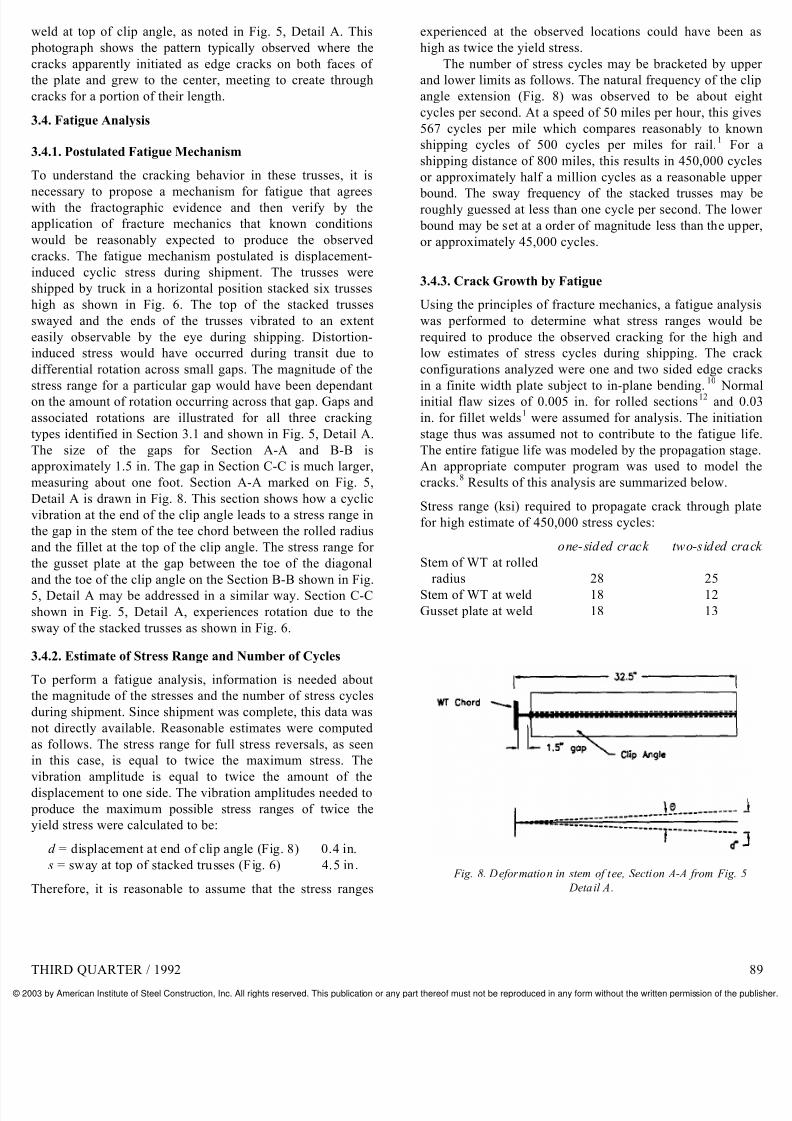
Detail A is drawn in Fig. 8. This section shows how a cyclic
vibration at the end of the clip angle leads to a stress range in
he gap in the stem of the tee chord between the rolled radius
nd the fillet at the top of the clip angle. The stress range for
he gusset plate at the gap between the toe of the diagonal
nd the toe of the clip angle on the Section B-B shown in Fig., Detail A may be addressed in a similar way. Section C-C
hown in Fig. 5, Detail A, experiences rotation due to the
way of the stacked trusses as shown in Fig. 6.
.4.2. Estimate of Stress Range and Number of Cycles
To perform a fatigue analysis, information is needed about
he magnitude of the stresses and the number of stress cycles
during shipment. Since shipment was complete, this data was
not directly available. Reasonable estimates were computed
s follows. The stress range for full stress reversals, as seen
n this case, is equal to twice the maximum stress. The
vibration amplitude is equal to twice the amount of thedisplacement to one side. The vibration amplitudes needed to
roduce the maximum possible stress ranges of twice the
yield stress were calculated to be:
d = displacement at end of clip angle (Fig. 8) 0.4 in.
s = sway at top of stacked trusses (Fig. 6) 4.5 in.
Therefore, it is reasonable to assume that the stress ranges
experienced at the observed locations could have bee
high as twice the yield stress.
The number of stress cycles may be bracketed by u
and lower limits as follows. The natural frequency of the
angle extension (Fig. 8) was observed to be about e
cycles per second. At a speed of 50 miles per hour, this g
567 cycles per mile which compares reasonably to kn
shipping cycles of 500 cycles per miles for rail.1
F
shipping distance of 800 miles, this results in 450,000 cy
or approximately half a million cycles as a reasonable u
bound. The sway frequency of the stacked trusses maroughly guessed at less than one cycle per second. The lo
bound may be set at a order of magnitude less than the up
or approximately 45,000 cycles.
3.4.3. Crack Growth by Fatigue
Using the principles of fracture mechanics, a fatigue ana
was performed to determine what stress ranges woul
required to produce the observed cracking for the high
low estimates of stress cycles during shipping. The c
configurations analyzed were one and two sided edge cr
in a finite width plate subject to in-plane bending.10
Noinitial flaw sizes of 0.005 in. for rolled sections
12and
in. for fillet welds1
were assumed for analysis. The initia
stage thus was assumed not to contribute to the fatigue
The entire fatigue life was modeled by the propagation st
An appropriate computer program was used to model
cracks.8
Results of this analysis are summarized below.
Stress range (ksi) required to propagate crack through p
for high estimate of 450,000 stress cycles:
one-sided crack two-sided c
Stem of WT at rolled
radius 28 25Stem of WT at weld 18 12
Gusset plate at weld 18 13
Fig. 8. Deformation in stem of tee, Section A-A from Fig.
Detail A.
THIRD QUARTER / 1992
3 by American Institute of Steel Construction, Inc. All rights reserved. This publication or any part thereof must not be reproduced in any form without the written permission of the

7/28/2019 29_3_085
http://slidepdf.com/reader/full/293085 6/7
Stress range (ksi) required to propagate crack through plate
or low estimate of 45,000 stress cycles:
one-sided crack two-sided crack
Stem of WT at rolled
radius 58 54
Stem of WT at weld 38 26
Gusset plate at weld 38 28
These stress ranges correspond to vibration amplitudes of
.04 in. (12 ksi) to 0.2 in. (58 ksi) at the end of the clip angle
nd 0.5 in. (12 ksi) to 2.5 in. (58 ksi) for sway at top of tacked trusses. These figures are well within expected
deflection ranges for trusses shipped in this manner.
.4.4. Fracture Toughness
The fractographic examination showed crack growth by
atigue with no indication of fast fracture. The fatigue
nalysis result had a maximum stress intensity factor, K, of
0.7 ksi in. The material test results showed a minimum
CVN of 18 ft-lb at 40°F. Using the two-stage CVN- K Id -K Icorrelation
13on the minimum CVN value gives a fracture
oughness of 51 ksi in. for a dynamic strain rate ( ε ≈ 10 –1
ec –1
) at a temperature of 40°F and a fracture toughness of 51ksi in. for an intermediate strain rate ( ε ≈ 10
–3sec
–1) at a
emperature of –62°F. This is in agreement with the observed
ehavior of crack growth only by fatigue for winter truck
hipment.
.5. Probable Cause and Sequence of Crack Growth
The probable cause of cracking was therefore concluded to
e displacement-induced cyclic stress during shipment. The
bserved crack locations were in thin plates subject to cyclic
ending where short gaps would be expected to result in a
eometric amplification of the cyclic stress leading to
racking. The cracks initiated on one or both faces of thelates, most frequently at the toe of fillet welds but
ometimes at a rolled radius. The cracks grew by fatigue
hrough the thickness of the plates. Vibration amplitudes of
.04 in. to 0.2 in. at the end of the clip angle and 0.5 in. to
.5 in. for sway at the top of stacked trusses are sufficient to
roduce the observed cracking over the given shipment
distance. The vibration amplitudes and number of loading
ycles required were in agreement with expected ranges for
russes shipped in this manner. For this case, blocking of the
lip angle (Fig. 5, Detail A) would be recommended for
roper shipping.
.6. Evaluation of Appropriateness of Repair Procedures
The cracks in the roof trusses were repaired by gouging and
ewelding. Although this was an appropriate repair technique
or building trusses subject to static loads, gouging and
ewelding is not an appropriate repair for bridge members.
An alternate suggested repair of drilling holes approximately
½-in. in diameter at the ends of the cracks was not used.
Either of these repair procedures were appropriate in view of
he cause of cracking and the required in-service behavior of
the trusses because further fatigue crack propagation du
service loading would not be expected.
The cracks in the stem of the tee at the rolled radius
at the top of the clip angle were in regions carrying negli
loads in service. This material could be completely coped
without decreasing the strength of the trusses for in-p
behavior. Gouging and rewelding was a more than adeq
fix in this region. Drilling holes at the end of the crack
eliminate the stress concentration at the sharp crack
would also have been a satisfactory fix.
The cracks at the ends of the diagonals were in a streregion of the gusset plate. Gouging and rewelding wa
adequate fix in this region. Where sufficient net area
sound weld remained for full load transfer, drilling hol
the ends of the cracks also would have provide
satisfactory repair at the ends of the diagonals. The cond
of the crack with end holes would have then been analo
to any other situation resulting in a reduced section at
location such as the presence of bolt holes or a penetra
opening through the gusset.
In summary, the cracks were caused by out-of-p
dynamic vibrations during shipment. The in-service tru
carry in-plane static loads. The cyclic stresses leadinfatigue crack growth are not present under service condit
and repaired cracks would not be expected to re-initiate.
In this case study, the fatigue cracks were detected
repairs performed. It is of interest to postulate the case w
the cracks were not detected and the resulting implicat
for in-service performance of the cracked trusses.
mentioned above, the cracks in the stem of the tee and a
top of the clip angle were essentially unstressed. The cr
at the ends of the diagonals did not reduce the section eno
to govern the load carrying capacity. The cracks would
grow by fatigue in-service, since the loads would be st
The existing cracks would not become unstable, under deloads, so fracture failure would not occur. Thus, for
particular case, the trusses would be expected to per
satisfactorily in-service even if the cracks were undetecte
4. CONCLUSIONS AND RECOMMENDATIONS
4.1. Conditions that Lead to Cracking During Shipmen
Two conditions must coexist to cause distortion-ind
cracking:
1. an abrupt change in stiffness, and2. a recurring displacement taking place across
stiffness discontinuity.
In addition, presence of a weld toe within this small re
acts as a crack initiation site and exacerbates the prob
These conditions conducive to cracking occur most freque
in plate girders, especially where there are small web g
The conditions may also arise for trusses, especially w
thin plates and heavy angles cause severe stiffness
0 ENGINEERING JOURNAL / AMERICAN INSTITUTE OF STEEL CONSTRUCT
3 by American Institute of Steel Construction, Inc. All rights reserved. This publication or any part thereof must not be reproduced in any form without the written permission of the
7/28/2019 29_3_085
http://slidepdf.com/reader/full/293085 7/7
hanges in the gussets. The extent of cracking will depend on
he specific gap configuration, the magnitude of the stress
anges induced by the distortions, and the number of fatigue
ycles. Particular connection details, plate thicknesses, and
displacements, as well as length of trip, thus all play a role.
.2. Effect of Cracking in Transit on Structural
Performance
When cracking occurs due to a low fatigue resistant detail or
large initial defect, only one or a few significant cracks are
usually generated. Observation of these cracks allows actiono be taken before cracking occurs at many points in the
tructure. Unlike this load-induced crack scenario, distortion-
nduced cracks frequently form at the same time in many
ocations. This means that many cracks must be repaired. For
racking that occurs during transit instead of during service,
t may be possible to restrict the number of cracks, depending
n the type of shipment. If a large number of components are
hipped in a similar fashion at the same time by rail, the
ossibility exists for many cracks to form simultaneously.
For components shipped by truck, careful examination of
omponents from the first truckloads shipped can provide a
warning so that relatively few cracks occur.Distortion-induced cracking during transit is usually due
o out-of-plane movement. Since components are designed for
n-plane behavior, the cracks usually form parallel to the
design tensile stresses. Such cracks running parallel to the in-
ervice stresses may not be harmful to the structure's
erformance as long as they are identified and repaired
efore they turn perpendicular to the in-service stresses.
Repair of these cracks is frequently straight forward,
specially for building components where cyclic stress are
not a major characteristic of in-service loads. The simplest
pproach is to drill out the crack tips and check the capacity
f the reduced section to carry design loads. Gouging andewelding is another alternative, for building components
where cracks are located in regions of low in-service stress
nd not subject to cyclic stresses, so that repaired cracks are
unlikely to re-initiate. Gouging and rewelding is not an
ppropriate repair for bridge members. More care must be
aken in the case of repair of cracked bridge components and
ase studies are available in the literature.1.9.5
.3. Prevention of Distortion-Induced Cracking During
Transit
When designing connection details and attachments such as
tiffeners, attention should be paid to how the member will
e shipped. Avoid creating short gaps which will be
ubjected to differential movement across the gap. If such a
ap must occur, the severity of the stiffness change may be
moothed out by elongating the gap, making the material in
the gap stiffer (usually by increasing its thickness) an
making the material bounding the gap more flexible (usu
by decreasing its thickness). Loads should be arranged
blocked properly to prevent distortions in gaps. Follow
good practice by careful inspection of components from
first truckloads shipped at the shop and at the site
rapidly identify transit cracking and avoid costly rejectio
rework on many components. Implementation of t
recommendations should minimize the possibility
distortion-induced cracking during transit.
REFERENCES
1. Fisher, John W., Fatigue and Fracture in Steel Bridges:
Studies, John Wiley & Sons, New York, 1984.
2. American Association of State Highway Officials, G
Specifications for Fatigue Design of Steel Bri
Washington, D.C., 1989.
3. AISC, Manual of Steel Construction, Allowable Stress De
1st ed. Chicago, IL, American Institute of Steel Constru
1989.
4. AISC, Manual of Steel Construction, Load and Resis
Factor Design, 9th ed. Chicago, IL, American Institute of
Construction, 1986.5. Kulicki, John M., and Dennis R. Mertz, Case Studi
Displacement-Induced Fatigue, Sixth Annual Stru
Congress, American Society of Civil Engineers, 1987.
6. Fisher, John. W., and Umur Yuceoglu, Fatigue and Fractu
Steel Bridges: Case Studies, Fritz Engineering Labo
Report 448-2(81), Lehigh University, Bethlehem, PA, 19
7. Demers, Cornelia E. and John W. Fisher, Fatigue Cracki
Steel Bridge Structures, Volume I: A Survey of Loca
Cracking in Steel Bridges—1981 to 1988, FHWA-RD-89
Federal Highway Administration, McLean, VA, 1990.
8. Roddis , W. M. Kim, Heuristic. Qualitat ive, and Quantit
Reasoning About Steel Bridge Fatigue and Fracture, P
Thesis, Civil Engineering Department, Massachusetts In
of Technology, Cambridge, MA, 1989.9. Fisher, John W., and Dennis. R. Mertz, Retrofitt ing
Bridges to Extend Their Fatigue Lives, The 1985 Interna
Engineering Symposium on Structural Steel, Am
Institute of Steel Construction. Chicago, IL, 1985.
10. Tada, H., P. C. Paris, and G. R. Irwin,The Stress Analy
Cracks Handbook, 2nd ed., Paris Productions, Inc.
Woodbourne Dr., St. Louis, MO, 1985.
11. AISI Technical Committee on Plates and Shapes
Variations of Charpy V-Notch Impact Test Properties in
Plates, American Iron and Steel Institute, Washington,
1979.
12. Fisher, J. W., K. H. Frank. M. A. Hirt, and B. M. McN
Effect of Weldments on the Fatigue Strength of Steel Be
National Cooperative Highway Research Program ReporTransportation Research Board, Washington, D.C., 1970.
13. Barsom, John M., and Stanley T. Rolfe, Fracture and Fa
Control in Structures, Prentice-Hall, Englewood Cliffs,
Jersey, 1987.
THIRD QUARTER / 1992


