Embed Size (px)
Citation preview
3GPP TR 25.818 V7.0.0 (2006-03)Technical Report
3rd Generation Partnership Project;Technical Specification Group TSG RAN;
UTRA tower mounted amplifier (FDD) study item technical report
(Release 7)
The present document has been developed within the 3rd Generation Partnership Project (3GPP TM) and may be further elaborated for the purposes of 3GPP. The present document has not been subject to any approval process by the 3GPP Organizational Partners and shall not be implemented. This Specification is provided for future development work within 3GPP only. The Organizational Partners accept no liability for any use of this Specification.Specifications and reports for implementation of the 3GPP TM system should be obtained via the 3GPP Organizational Partners' Publications Offices.
3GPP TR 25.818 V7.0.0 (2006-03)2Release 7T
Keywords UMTS, radio
3GPP
Postal address
3GPP support office address 650 Route des Lucioles - Sophia Antipolis
Valbonne - FRANCE Tel.: +33 4 92 94 42 00 Fax: +33 4 93 65 47 16
Internet http://www.3gpp.org
Copyright Notification
No part may be reproduced except as authorized by written permission. The copyright and the foregoing restriction extend to reproduction in all media.
© 2006, 3GPP Organizational Partners (ARIB, ATIS, CCSA, ETSI, TTA, TTC).
All rights reserved.
3GPP

3GPP TR 25.818 V7.0.0 (2006-03)3Release 7T
Contents Foreword ............................................................................................................................................................5 1 Scope ........................................................................................................................................................5 2 References ................................................................................................................................................5 3 Definitions, symbols and abbreviations ...................................................................................................6 3.1 Definitions ......................................................................................................................................................... 6 3.2 Symbols ............................................................................................................................................................. 6 3.3 Abbreviations..................................................................................................................................................... 6 4 Objectives.................................................................................................................................................6 5 TMA – Base Station Antenna configurations ..........................................................................................6 5.1 TMA configuration ............................................................................................................................................ 6 5.2 RET configuration ............................................................................................................................................. 8 6 Radio Requirements that need to be standardized for TMA ....................................................................8 6.1 Introduction........................................................................................................................................................ 8 6.2 List of Radio Requirements expected for the UTRA TMA ............................................................................... 9 6.2.1 IMD requirements for the 3GPP TMA....................................................................................................... 10 7 Standardization of UTRA FDD TMA radio requirements.....................................................................11 7.1 Different Alternatives ...................................................................................................................................... 11 7.1.1 Current situation......................................................................................................................................... 11 7.1.2 TMA Standardization Alternative 1 ........................................................................................................... 12 7.1.3 TMA Standardization Alternative 2 ........................................................................................................... 13 7.1.4 TMA Standardization Alternative 3 ........................................................................................................... 14 7.2 Conformance testing and overall system responsibility................................................................................... 15 7.2.1 TMA standardisation alternative 1 ............................................................................................................. 15 7.2.1.1 Aspects related to conformance testing ................................................................................................ 15 7.2.1.2 Aspects related to overall system responsibility................................................................................... 15 7.2.2 TMA standardisation alternative 2 ............................................................................................................. 16 7.2.2.1 Aspects related to conformance testing ................................................................................................ 16 7.2.2.2 Aspects related to overall system responsibility................................................................................... 16 7.2.3 TMA standardisation alternative 3 ............................................................................................................. 16 7.2.3.1 Aspects related to conformance testing ................................................................................................ 16 7.2.3.2 Aspects related to overall system responsibility................................................................................... 16 7.3 Structure of the radio requirements.................................................................................................................. 16 7.3.1 TMA Mandatory requirements ........................................................................................................................ 16 7.3.2 TMA Alternative requirements .................................................................................................................. 17 7.3.3 TMA Optional requirements............................................................................................................................ 17 7.3.4 TMA Ratings.............................................................................................................................................. 18 7.3.5 TMA Band options..................................................................................................................................... 18 7.3.6 Structure of Radio Requirements related to TMA for BS+TMA (FFS)..................................................... 18 7.3.7 Structure of Radio Requirements related to TMA for BS (FFS)................................................................ 18 7.4 Feasibility of splitting radio requirements between Radio Basestation and UTRA FDD TMA...................... 18 7.4.1 Dividing IMD contributions between 3GPP TMA and BS.............................................................................. 18 7.4.2 Feasibility of defining IMD requirements for the 3GPP TMA........................................................................ 20 7.4.3 Summary of the feasibility of splitting the radio requirements between base station and 3GPP TMA ........... 21 8 Impact on current specifications ............................................................................................................21 8.1 Impact on TS 25.104........................................................................................................................................ 21 8.1.1 TMA standardisation alternative 1 ............................................................................................................. 21 8.1.2 TMA standardisation alternative 2 ............................................................................................................. 21 8.1.3 TMA standardisation alternative 3 ............................................................................................................. 22 8.1.4 General ....................................................................................................................................................... 22 8.2 Impact on TR 25.942 ....................................................................................................................................... 22 8.2.1 TMA standardisation alternative 1 ............................................................................................................. 22 8.2.2 TMA standardisation alternative 2 ............................................................................................................. 22
3GPP

3GPP TR 25.818 V7.0.0 (2006-03)4Release 7T
8.2.3 TMA standardisation alternative 3 ............................................................................................................. 22 8.3 Impact on Radio Resource Management requirements.................................................................................... 22 9 Conclusion..............................................................................................................................................23
Annex A: Change history ......................................................................................................................25
3GPP
3GPP TR 25.818 V7.0.0 (2006-03)5Release 7T
Foreword This Technical Report has been produced by the 3rd Generation Partnership Project (3GPP).
The contents of the present document are subject to continuing work within the TSG and may change following formal TSG approval. Should the TSG modify the contents of the present document, it will be re-released by the TSG with an identifying change of release date and an increase in version number as follows:
Version x.y.z
where:
x the first digit:
1 presented to TSG for information;
2 presented to TSG for approval;
3 or greater indicates TSG approved document under change control.
y the second digit is incremented for all changes of substance, i.e. technical enhancements, corrections, updates, etc.
z the third digit is incremented when editorial only changes have been incorporated in the document.
3GPP
3GPP TR 25.818 V7.0.0 (2006-03)6Release 7T
1 Scope This document is the technical report of the UTRA Tower Mounted Amplifier (FDD) SI which was approved in TSG RAN meeting #28 [1].
The purpose of this TR is to summarize the study of different alternatives how external low noise RX amplifier radio requirements for UTRA FDD could be standardized.
2 References The following documents contain provisions which, through reference in this text, constitute provisions of the present document.
• References are either specific (identified by date of publication, edition number, version number, etc.) or non-specific.
• For a specific reference, subsequent revisions do not apply.
• For a non-specific reference, the latest version applies. In the case of a reference to a 3GPP document (including a GSM document), a non-specific reference implicitly refers to the latest version of that document in the same Release as the present document.
[1] RP-050387, SID: UTRA FDD TMA
[2] R4-051150 / TELCO_TMA_27_10_05_Nortel#01 On TMA Architecture
[3] 3GPP TR 21.905: "Vocabulary for 3GPP Specifications".
3 Definitions, symbols and abbreviations
3.1 Definitions For the purposes of the present document, the terms and definitions given in TR 21.905 [3] and the following apply. A term defined in the present document takes precedence over the definition of the same term, if any, in TR 21.905 [3].
3.2 Symbols For the purposes of the present document, the abbreviations given in TR 21.905 [3] and the following apply. An abbreviation defined in the present document takes precedence over the definition of the same abbreviation, if any, in TR 21.905 [3].
3.3 Abbreviations For the purposes of the present document, the following abbreviations apply:
TMA Tower Mounted Amplifiers; external low noise RX amplifier
4 Objectives The objectives of this study item are:
- Identification of the radio requirements, which need to be standardized for external low noise Tower Mounted Amplifier (TMA) in Rx for UTRA FDD.
3GPP

3GPP TR 25.818 V7.0.0 (2006-03)7Release 7T
- The feasibility of splitting the radio requirements between base station and UTRA FDD TMA.
- Alternatives how UTRA FDD TMA radio requirements could be standardized.
- How to structure UTRA FDD TMA radio requirements (e.g. a single set of UTRA FDD TMA requirements supporting all BS configurations or multiple sets of requirements?)
- Impact on current specifications TS 25.104, TS 25.141, and TR 25.942.
- Impact on RRM measurements.
- Impact on conformance testing and overall system responsibility.
5 TMA – base station antenna configurations This clause identifies information about configurations (Bands, Antennas, etc…) considered for TMA TR.
5.1 TMA configuration Losses and the Delays introduced by feeders between Base Station and the remote TMA are important to specify 3GPP-TMAs. As we will have to face several 3GPP-TMA kinds, we should identify the possible architectures (e.g with/without Rx/TX diversity, with RET modem, etc..) in order to derive how to specify 3GPP-TMAs. The following block diagrams give examples of BS-TMAs configurations.
3GPP-TMA MastHead Module
Div
MainNode B intended to be use with 3GPP-TMA
Figure 5.1: Example of Base Station – TMA architecture (Rx Div / No Tx div)
3GPP
3GPP TR 25.818 V7.0.0 (2006-03)8Release 7T
3GPP-TMA Mast Head Module
Div
Main
Node B intended to be use with 3GPP-TMA
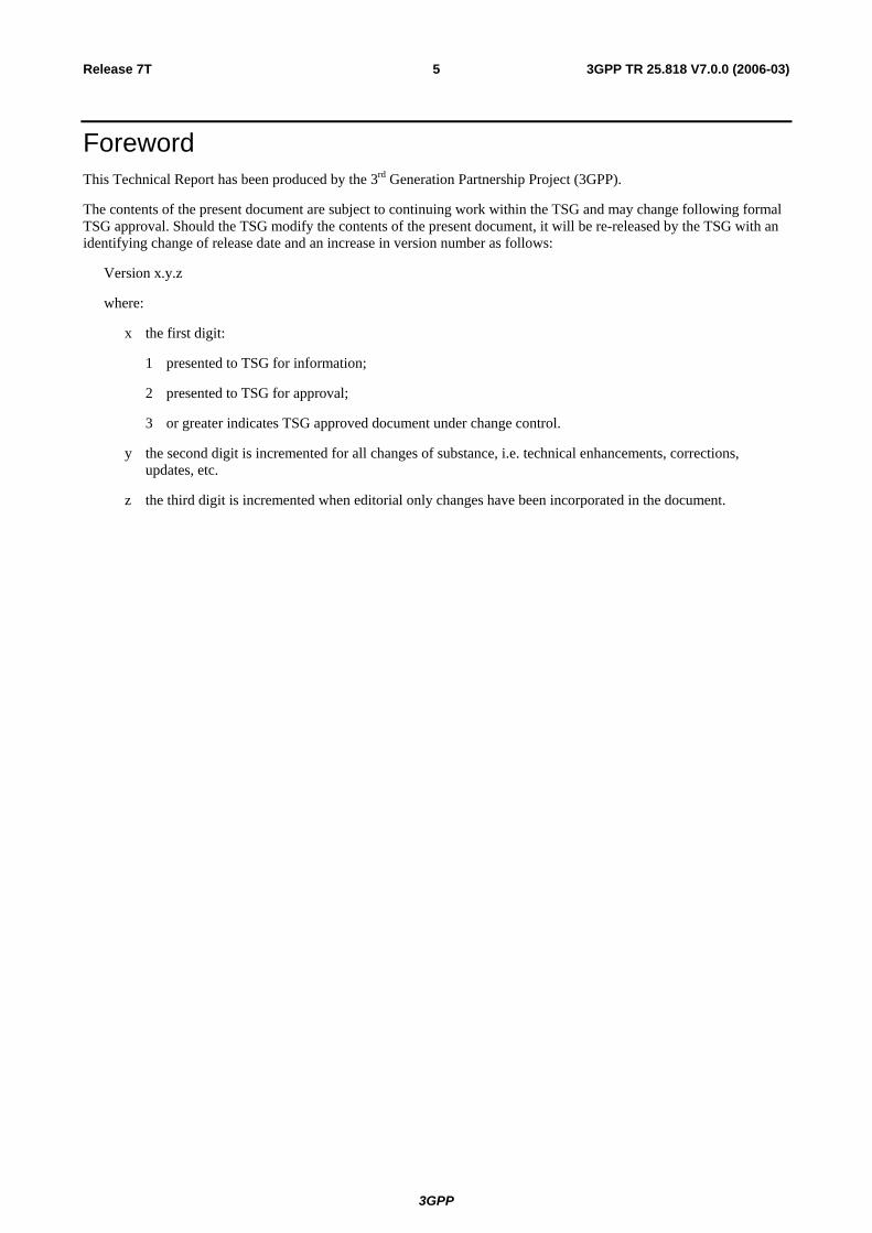
Figure 5.2: Example of Base Station – TMA architecture (Rx Div / Tx div)
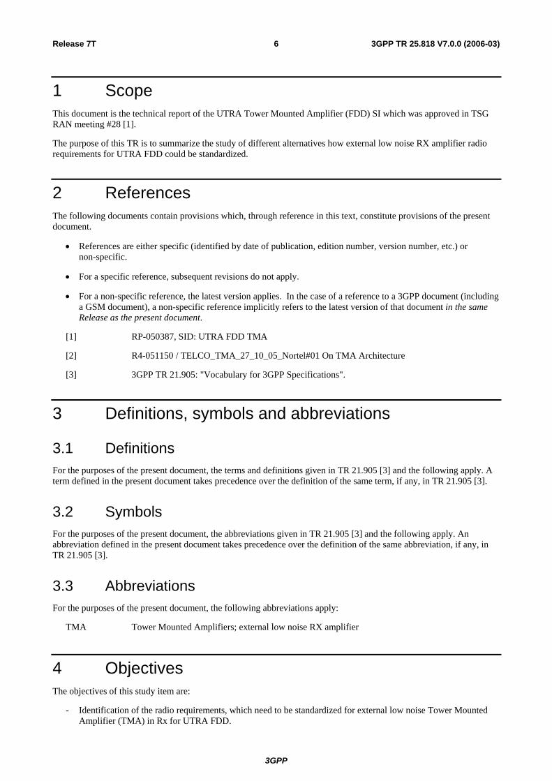
From those configurations, we could identify 3 main blocks which could be consider as functional blocks from which all the other possible configurations could be derived. [2] provides a more complete list of possible architectures.
Fig 5.3: Building blocks for 3GPP-TMA Architectures
It is proposed to study the 3GPP-TMA RF parameters for those 3 building blocks.
5.2 RET configuration The 3GPP TMA could be powered thought a separate Power source but most frequently by the DC component carried by the feeder with a classical scheme as shown below. In addition, the equivalent to the AISG signalling could also be part of the additional information carried over the same feeder.
3GPP
3GPP TR 25.818 V7.0.0 (2006-03)9Release 7T
RET modem
DC extraction
DC Power used for the RET and the LNA Data port
3GPP -TMA
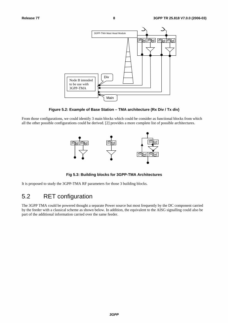
Figure 5.4: 3GPP-TMA configuration with RET integrated
With such configuration, we could derive the need to duplicate the number of Delays Parameters requested at the Base Station to handle the presence of the RET modem. This is also true for the ByPass function where TMA is considered as transparent.
RF interaction between RET and LNA inside the TMA block are FFS.
6 Radio requirements that need to be standardized for TMA
This clause identify radio requirements, which need to be standardized for external low noise Tower Mounted Amplifier (TMA) in Rx for UTRA FDD Alternatives of standardizing UTRA FDD TMA radio requirements.
6.1 Introduction TMAs have a vendor-defined performance and characteristics, as currently there do not exist 3GPP requirements applicable to a TMA only. However, TS 25.104/141 do contain minimum performance requirements at test port B for a cascaded chain TMA + BS which are identical with those for the BS.
Within the current framework, in order for a BS system vendor to provide a TMA + BS solution meeting the 3GPP minimum performance requirements at test port B and possibly additional requirements for interference free operation in the relevant operating scenarios, an appropriate partitioning of radio parameters related to the TMA – BS antenna line interface is performed; examples are partitioning of interference contributions due to IMD, receive chain gain distribution, etc. From this partitioning of radio parameters, TMA specific radio requirements are subsequently derived and other necessary electrical requirements added.
Assuming that the intent of a 3GPP TMA specification is to ensure robust system performance of any vendors 3GPP conforming TMA cascaded with any system vendors 3GPP conforming BS without any additional responsibility of the system vendor, it is expected that a similar process as described above needs to be followed. It is also expected that the set of 3GPP TMA radio requirements would need to have a scope comparable to today’s (system) vendor specific TMA specification.
Hence, in order to identify the relevant radio requirements and conformance tests for a 3GPP TMA the following areas need to be analysed:
a) Minimum performance requirements at test port B as per TS 25.104/141 with a 3GPP TMA. This will lead to 3GPP TMA requirements in the areas of IMD, gain, modulation accuracy (EVM), etc.
b) Additional requirements to ensure interference free operation in all relevant operating scenarios (e.g. co-location with GSM1800) and which may be part of today’s vendor specific TMA specification (responsibility).
3GPP

3GPP TR 25.818 V7.0.0 (2006-03)10Release 7T
c) Additional electrical parameters related to the proper functioning of the TMA – BS antenna line interface (e.g. impedance, (peak) power handling capability, RL, PIM, etc.).
d) Other TMA specific RF parameters which may be of interest to the operator (e.g. TX path IL, maximum input power, etc)
6.2 List of radio requirements expected for the UTRA TMA Based on the previously mentioned areas a.), …, d.) the following is a tentative list of radio requirements expected for the UTRA TMA:
- Operating bands .
- Operating bandwidth .
- Nominal RX passband gain. There will be requirements on permissible 3GPP TMA gain values in order for a TMA+BS chain to still meet the TS 25.104 requirements at test port B (this is related to the possible generation of IMD within the BS in presence of overgain and to dynamic range limitations). The gain distribution within the BS receive chain typically supports only very few discrete settings and makes definite assumptions about the TMA gain present. Furthermore, 3GPP TMA IMD requirements need to be based on a specific (maximum) value for the nominal gain, see separate section 2.1.
- RX passband gain variation (related to RTWP requirements in TS 25.133)
- Over operating frequency
- Over operating temperature
- Out-band gain mask (related to the TMA RX filtering). There will be requirements on a permissible 3GPP TMA out-band gain mask in order for a TMA+BS chain to still meet the TS 25.104 requirements at test port B (this is related to the possible generation of IMD within the BS in presence of overgain on out-band interferers). Furthermore, 3GPP TMA IMD requirements need to be based on a specific assumptions on the out-band gain mask, see separate section 2.1.
- NF (one constraint is that the TMA+BS chain has to meet the TS 25.104 reference sensitivity requirement at test port B)
- NF variation
- Over operating temperature
- EVM on RX path (due to filter GDD). This is related to the TS 25.104 demodulation performance requirement at test port B. The total permissible EVM of the TMA + BS RF chain needs to be established and then be divided between 3GPP TMA and BS. This division (and hence the TMA requirement) may depend on the operating band.
- RX path time delay (related to UTRAN measurements in TS 25.215)
- 1 dB compression
- RX IL
- Bypass mode
- Passive intermodulation (PIM). Requirements may depend on the operating band.
- “Active” IMD requirements (see separate section 2.1).
- Channel isolation
- Maximum power handling. This requirement depends on the BS transmitter characteristics (e.g. PAR) and carrier configurations, which need to be supported, however, these are not defined in TS 25.104. There will be a trade-off between 3GPP TMA mechanical size and cost vs. range of supported BS TX configurations. Furthermore, 3GPP TMA IMD requirements need to be based on a specific (maximum) carrier TX power value, see separate section 6.2.1.
3GPP

3GPP TR 25.818 V7.0.0 (2006-03)11Release 7T
- CW or # of carriers @ specified RMS power
- Peak power
- RL (VSWR)
- Normal operating mode
- Bypass mode
- TX IL
- TX IL variation
- Over operating frequency
- Over operating temperature
- EVM on TX path (due to filter GDD). This is related to the TS 25.104 EVM requirement at test port B. The total permissible EVM of the TMA + BS RF chain needs to be divided between 3GPP TMA and BS. This division (and hence the TMA requirement) may depend on the operating band.
- TX path time delay (related to UTRAN measurements in TS 25.215)
6.2.1 IMD requirements for the 3GPP TMA Tentative list of IMD scenarios
The following is a tentative list of IMD scenarios, which need to be analysed in order to derive suitable 3GPP TMA IMD requirements. In addition to those IMD scenarios, which can be directly related to the TS 25.104 minimum performance requirements (at test port B), a few IMD scenarios have been added which may be of interest for the operator and/or may be part of today’s (system) vendor specific TMA specification in order to ensure minimal interference under a wide range of operating scenarios. To ensure minimal interference under a wide range of operating scenarios the number of scenarios, interference levels and allowed degradation would need be discussed and further analyzed during a WI phase.
1) 3rd order IMD from 2 x (-48 dBm) inband interfering signals
2) 3rd order IMD from 2 x (-47 dBm) inband interfering NB signals (Bands II, III, V, …)
3) 7th order IMD from 2 x (own TX carrier) (Band I)
4) 3rd order IMD from 2 x (own TX carrier) (Bands II, III, V, …)
5) 7th order IMD from +16 dBm co-sited inband interfering signal + own TX carrier (Band I)
6) 3rd order IMD from +16 dBm co-sited inband interfering signal + own TX carrier (Bands II, III, V, …)
7) 3rd order IMD from 2 x (+16 dBm co-sited other-band interfering signal) (Example: 2 x GSM1800 co-sited carriers causing IMD into Band I)
8) 3rd order IMD from -15 dBm out-band interfering signal + own TX carrier
9) 3rd order IMD from -40 dBm inband interfering signal + own TX carrier (Bands II, III, V, …)
10) 3rd order IMD from -40 dBm inband interfering signal + (+16 dBm co-sited inband interfering signal) (Bands II, III, V, …)
11) XMD from -47 dBm inband interfering NB signal + own TX carrier (Bands II, III, V, …)
12) XMD from -47 dBm inband interfering NB signal + (+16 dBm co-sited inband interfering signal) (Bands II, III, V, …)
13) 3rd order IMD from +16 dBm co-sited Band I interfering signal + (+16 dBm co-sited Band III interfering signal) falling into Band VII BS RX band
3GPP
3GPP TR 25.818 V7.0.0 (2006-03)12Release 7T
14) 3rd order IMD from +16 dBm co-sited Band II interfering signal + Band IV own TX carrier falling into Band IV BS RX band
In here, it is not proposed to enlarge the set of currently defined minimum performance requirements of TS 25.104 at test port B by the above additional IMD scenarios, but it is proposed to consider them when deriving 3GPP TMA IMD requirements in order to ensure that the TMA will not be the dominant source of IMD for this wider range of operating scenarios.
7 Standardization of UTRA FDD TMA radio requirements
7.1 Different alternatives This clause lists different alternatives how UTRA FDD TMA radio requirements could be standardized. It focuses on alternatives for a new TMA specification TS25.1XX and new requirements to be added in TS25.104 for that purpose.
Issues related to feasibility of TMA conformance testing and related to overall system responsibility are out of the scope of this section, they will be discussed in clause 7.2.
7.1.1 Current situation
3GPP BS
A
TMA
B
BS
Feeder cable
Feeder cable
TS 25.104
TS 25.104
or
Figure 7.1
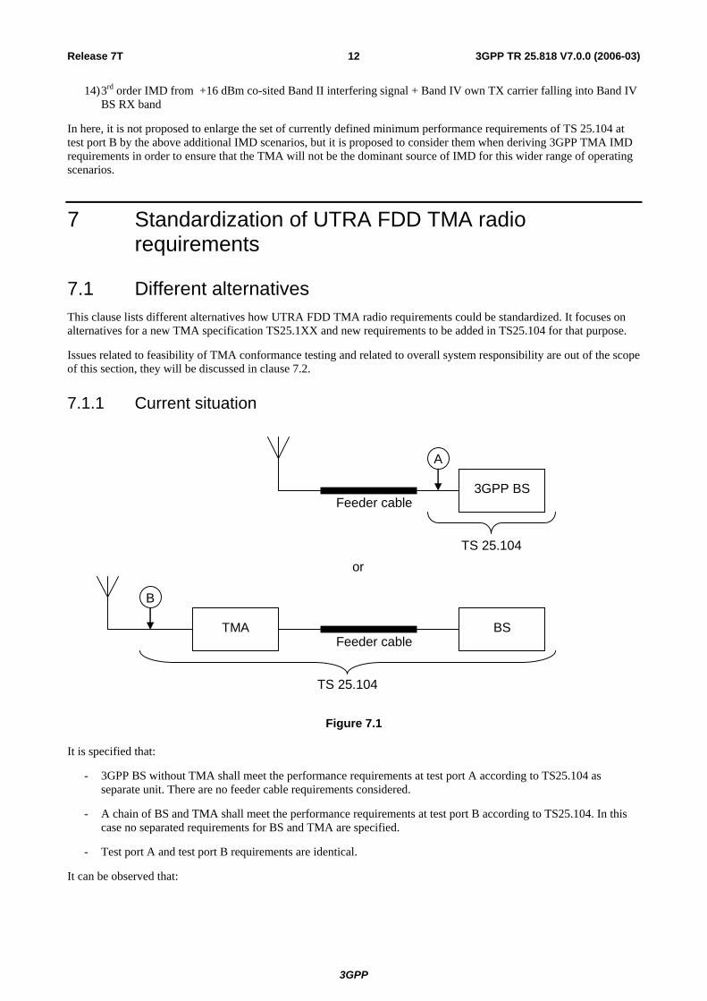
It is specified that:
- 3GPP BS without TMA shall meet the performance requirements at test port A according to TS25.104 as separate unit. There are no feeder cable requirements considered.
- A chain of BS and TMA shall meet the performance requirements at test port B according to TS25.104. In this case no separated requirements for BS and TMA are specified.
- Test port A and test port B requirements are identical.
It can be observed that:
3GPP
3GPP TR 25.818 V7.0.0 (2006-03)13Release 7T
- The interface between BS and TMA is not standardized, how RF requirements and RF performance is partitioned between BS and TMA and how the feeder cable between BS and TMA is considered is therefore implementation specific.
- When a new active RF element is added between BS and antenna, the BS requirement will have to differ from the port A requirement to meet the port B requirement for the whole chain.
For a standardization of TMA, the interface between BS and TMA needs to be specified. In order to guarantee the inter-working of BS and TMA of different vendors, this interface needs to be specified for both BS and TMA. Different alternative approaches are described in the subsequent sections.
7.1.2 TMA standardization alternative 1
3GPP TMA
C
3GPP TMA
B’
BS Feeder cable
New TS 25.1xx
Revised TS 25.104/25.141
D
Figure 7.2
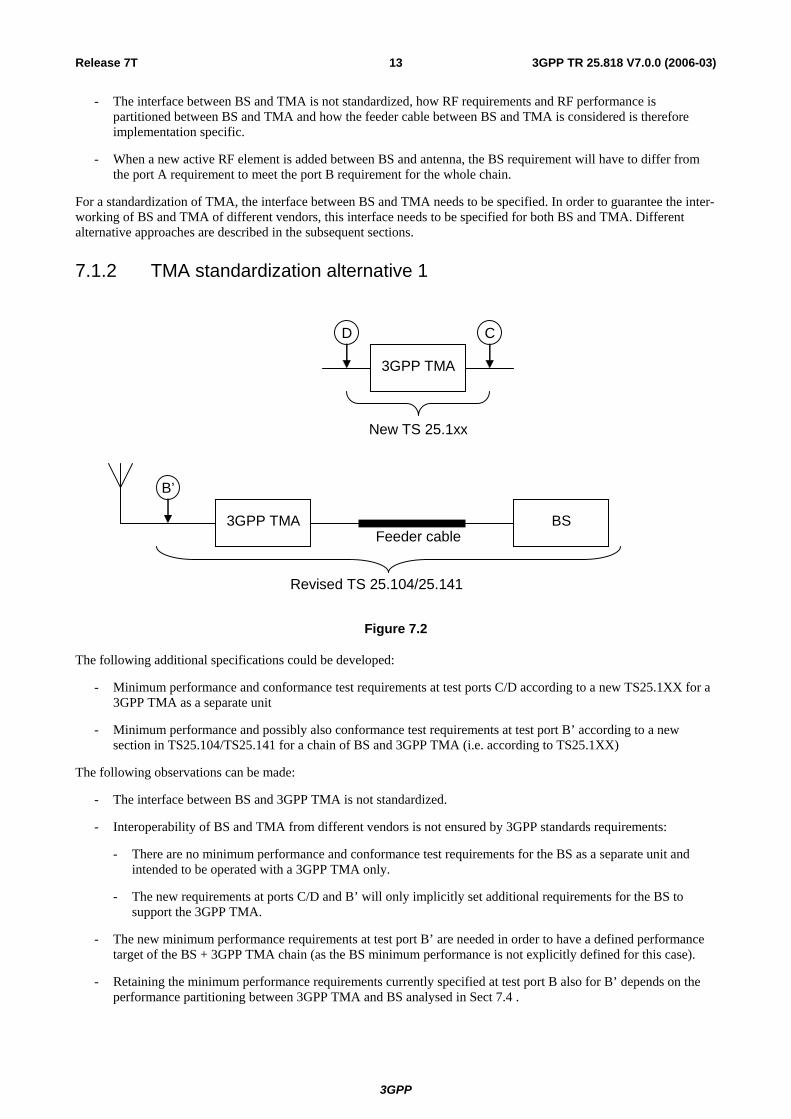
The following additional specifications could be developed:
- Minimum performance and conformance test requirements at test ports C/D according to a new TS25.1XX for a 3GPP TMA as a separate unit
- Minimum performance and possibly also conformance test requirements at test port B’ according to a new section in TS25.104/TS25.141 for a chain of BS and 3GPP TMA (i.e. according to TS25.1XX)
The following observations can be made:
- The interface between BS and 3GPP TMA is not standardized.
- Interoperability of BS and TMA from different vendors is not ensured by 3GPP standards requirements:
- There are no minimum performance and conformance test requirements for the BS as a separate unit and intended to be operated with a 3GPP TMA only.
- The new requirements at ports C/D and B’ will only implicitly set additional requirements for the BS to support the 3GPP TMA.
- The new minimum performance requirements at test port B’ are needed in order to have a defined performance target of the BS + 3GPP TMA chain (as the BS minimum performance is not explicitly defined for this case).
- Retaining the minimum performance requirements currently specified at test port B also for B’ depends on the performance partitioning between 3GPP TMA and BS analysed in Sect 7.4 .
3GPP
3GPP TR 25.818 V7.0.0 (2006-03)14Release 7T
- In case alternative gain values are specified for the 3GPP TMA, multiple sets of requirements at test port B’ may be required for each gain alternative (refer to Sect. 7.3) but the aim should be that the different gain alternatives would impose different sets of implicit requirements for the BS. This is due to the fact that each gain alternative will impact the BS performance differently (e.g. IMD) and different behavior of the BS+TMA chain at test port B’ should be avoided.
- It is not evident, how the conformance of the BS + 3GPP TMA chain with the minimum performance requirements at test port B’ can be ensured (refer to Sect. 7.2).
7.1.3 TMA standardization alternative 2
3GPP TMA
B*
3GPP BS Feeder cable
TS 25.104
Additional requirements in TS 25.104
3GPP TMA
Y
3GPP BS Feeder cable
New TS 25.1xx
X A
Figure 7.3
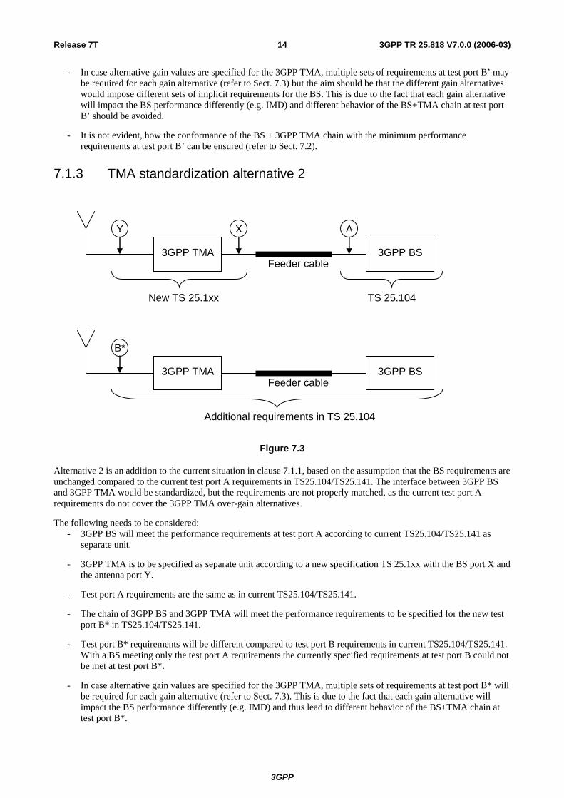
Alternative 2 is an addition to the current situation in clause 7.1.1, based on the assumption that the BS requirements are unchanged compared to the current test port A requirements in TS25.104/TS25.141. The interface between 3GPP BS and 3GPP TMA would be standardized, but the requirements are not properly matched, as the current test port A requirements do not cover the 3GPP TMA over-gain alternatives.
The following needs to be considered: - 3GPP BS will meet the performance requirements at test port A according to current TS25.104/TS25.141 as
separate unit.
- 3GPP TMA is to be specified as separate unit according to a new specification TS 25.1xx with the BS port X and the antenna port Y.
- Test port A requirements are the same as in current TS25.104/TS25.141.
- The chain of 3GPP BS and 3GPP TMA will meet the performance requirements to be specified for the new test port B* in TS25.104/TS25.141.
- Test port B* requirements will be different compared to test port B requirements in current TS25.104/TS25.141. With a BS meeting only the test port A requirements the currently specified requirements at test port B could not be met at test port B*.
- In case alternative gain values are specified for the 3GPP TMA, multiple sets of requirements at test port B* will be required for each gain alternative (refer to Sect. 7.3). This is due to the fact that each gain alternative will impact the BS performance differently (e.g. IMD) and thus lead to different behavior of the BS+TMA chain at test port B*.
3GPP

3GPP TR 25.818 V7.0.0 (2006-03)15Release 7T
- The impact of the feeder cable between 3GPP BS and 3GPP TMA on requirements at ports X, Y, and B* is analysed in Sect 7.4 .
- The impact of deviating port B* requirements compared to port B requirements on system performance is analysed in Sect 7.1.
- The impact of different port B* requirements on 3GPP TMA complexity/cost is to be considered when the break down of the requirements is done.
7.1.4 TMA standardization alternative 3
3GPP TMA
B
New 3GPP BS Feeder cable
Additional requirements in TS 25.104
TS 25.104
3GPP TMA
Y
New 3GPP BS Feeder cable
New TS 25.1xx
X A*
Figure 7.4
Alternative 3 is an addition to the current situation in clause 7.1.1, based on the assumption that the chain of standardized BS and TMA will meet the same performance as currently specified for the test port B in TS25.104/TS25.141. This requires revised BS requirements. The interface between 3GPP BS and 3GPP TMA would be standardized.
The following needs to be considered: - A new 3GPP BS type to be operated with 3GPP TMA only is to be specified by new requirements in
TS25.104/TS25.141 with test port A* as separate unit.
- 3GPP TMA is to be specified as separate unit according to a new specification TS 25.1xx with the BS port X and the antenna port Y.
- The chain of 3GPP BS and 3GPP TMA shall meet the performance requirements for test port B in TS25.104/TS25.141.
- Test port A* requirements will be different compared to test port A requirements in current TS25.104/TS25.141. The detailed list of the radio requirements for the BS at test port A* will differ from those at test port A and is analysed in Sect 7.3.
- In case alternative gain values are specified for the 3GPP TMA, multiple sets of requirements at test port A* will be required for each gain alternative (refer to Sect. 7.3). This is due to the fact that each gain alternative will impact the BS performance differently (e.g. IMD).
- Test port B requirements may be the same as in current TS25.104. This would depend on the outcome of the performance partitioning between 3GPP TMA and BS and is analysed in Sect 7.4.
3GPP
3GPP TR 25.818 V7.0.0 (2006-03)16Release 7T
- The impact of the feeder cable between 3GPP BS and 3GPP TMA on requirements at ports A*, X and Y is analysed in Sect 7.3.
- The feasibility of a partition of RF requirements between 3GPP BS and 3GPP TMA is analysed in Sect 7.4 and further analysis would have to consider complexity and cost constraints for BS and TMA.
7.2 Conformance testing and overall system responsibility This clause identifies the impact on conformance testing and the overall system responsibility when standardizing external low noise Tower Mounted Amplifier (TMA) in Rx for UTRA FDD. Properly standardised interfaces should ensure interoperability as long as the involved units conform to their respective requirements. This obviously requires conformance test specifications to be available for both units of the interface.
The notion of “overall system responsibility”, as it goes beyond mere standards and testing is not well defined and as such outside the scope of 3GPP and this TR. Nevertheless, some brief considerations are provided here.
Properly standardised interfaces should ensure interoperability without relying on some party taking the “overall system responsibility” for interoperability, i.e. the interoperability should be ensured by appropriate standard’s design and the conformance testing for the involved units.
7.2.1 TMA standardisation alternative 1
7.2.1.1 Aspects related to conformance testing
Regarding TMA standardisation alternative 1 it was observed in Sect. 7.1.2 that the interface between BS and 3GPP TMA is not standardised, as there are no minimum performance and conformance test requirements available for the BS as a separate unit and intended to be operated with a 3GPP TMA only. Hence, 3GPP standards requirements do not facilitate the interoperability of BS and TMA from different vendors in this alternative.
The interoperability of BS and TMA from different vendors could only be ensured by additional arrangements, which are, however, outside the scope of 3GPP to elaborate further. E.g., in case that conformance test requirements at test port B’ would be available, it may be considered that the BS vendor, the network operator or another 3rd party would perform conformance tests for the BS + 3GPP TMA chain. This would raise a number of open questions, e.g. it is not clear which particular TMA (or possibly a specific test equipment representing the 3GPP TMA?) should be substituted in order to declare conformance at test port B’ for the BS + 3GPP TMA chain. It is also not clear how to verify that the BS is appropriately designed as there are no minimum performance requirements (and tests) available for the BS. These and a number of related questions are, however, of commercial nature and thus outside the scope of 3GPP and this TR.
In summary, this standardisation alternative does not facilitate the interoperability of BS and TMA from different vendors in any better way than today’s standards situation as described in Sect. 7.1.1
7.2.1.2 Aspects related to overall system responsibility
It was pointed out in Sect. 6.2 that there might exist additional requirements for the BS+TMA chain (e.g. in the area of IMD, please refer to Subsection 6.2.1 “Tentative list of IMD scenarios”) to ensure interference free operation in all relevant operating scenarios, which may be part of today’s vendor BS and TMA specifications, but are not visible in the test port B requirements and conformance tests.
Assuming that the test port B’ requirements and conformance tests of TMA standardisation alternative 1 are in their scope comparable to those currently defined at test port B (and this appears to be the working assumption), it is difficult to see how it could be avoided that some party assumes the “overall system responsibility”. In order to avoid this, a more comprehensive set of requirements than currently specified for test port B may be required at test port B’ for each TMA gain alternative, this aspect is FFS.
Also regards this aspect, standardisation alternative 1 does not facilitate the interoperability of BS and TMA from different vendors in any better way than today’s standards situation as described in Sect. 7.1.1 and is therefore not recommended as a feasible way forward.
3GPP
3GPP TR 25.818 V7.0.0 (2006-03)17Release 7T
7.2.2 TMA standardisation alternative 2
7.2.2.1 Aspects related to conformance testing
Regarding TMA standardisation alternative 2 it was observed in Sect. 7.1.3 that the interface between 3GPP BS and 3GPP TMA is standardised. There will be minimum performance and conformance test requirements for both the 3GPP BS and 3GPP TMA as separate units. Based on the assumptions in Sect. 7.1.3, minimum requirements and conformance test requirements for the 3GPP BS will be identical to those in today’s standards situation as described in Sect. 7.1.1.
It is the working assumption that the Port B* requirements for the chain of 3GPP BS and 3GPP TMA in TMA standardisation alternative 2 will be met if 3GPP BS and 3GPP TMA are compliant to their specifications, hence there shall be no need for additional conformance tests of the chain of 3GPP BS and 3GPP TMA. To ensure this, appropriate requirements for the TMA need to be specified, however, it cannot be precluded that additional requirements for the 3GPP BS (compared to those in today’s standards situation as described in Sect. 7.1.1) will be also necessary.
7.2.2.2 Aspects related to overall system responsibility
With respect to the underlying assumptions regarding standardisation alternative 2, interoperability and port B* performance for the 3GPP BS – 3GPP TMA chain is ensured by standard’s design and the conformance testing for the involved units.
7.2.3 TMA standardisation alternative 3
7.2.3.1 Aspects related to conformance testing
Regarding TMA standardisation alternative 3 it was observed in Sect. 7.1.4 that the interface between 3GPP BS and 3GPP TMA is standardised. There will be minimum performance and conformance test requirements for both the 3GPP BS and 3GPP TMA as separate units. Based on the assumptions in Sect. 7.1.4, minimum requirements and conformance test requirements for the 3GPP BS will be different to those in today’s standards situation as described in Sect. 7.1.1.
It is the working assumption that the Port B requirements for the chain of 3GPP BS and 3GPP TMA in TMA standardisation alternative 3 will be met if 3GPP BS and 3GPP TMA are compliant to their specifications, hence there shall be no need for additional conformance tests of the chain of 3GPP BS and 3GPP TMA. It is noted in Sect. 7.1.4 that the port B requirements in alternative 3 may be different compared to those in today’s standards situation as described in Sect. 7.1.1, however, it is anticipated that this does not affect conformance testing.
7.2.3.2 Aspects related to overall system responsibility
With respect to the underlying assumptions regarding standardisation alternative 3, interoperability and port B performance for the 3GPP BS – 3GPP TMA chain is ensured by standard’s design and the conformance testing for the involved units.
7.3 Structure of the radio requirements This clause identifies how to structure UTRA FDD TMA radio requirements, e.g. a single set of UTRA FDD TMA requirements supporting all BS configurations or multiple sets of requirements?
7.3.1 TMA mandatory requirements For any TMA specification it is expected to have most of the TMA requirements to be mandatory. That would make it easier for the operator to know that he orders the right TMA for the specific application and would also ensure a better defined performance of the BS + 3GPP TMA chain.
Many of the mandatory requirements, in particular those which drive the TMA cost, will be different for each of the different operating bands as well as for each of the different gain alternatives. Hence, one would need to consider one whole set of mandatory requirement for each operating band as well as for each gain alternative. This would mean that the number of requirement sets to be defined for the TMA and BS is: (# of operating bands) *(# of gain alternatives).
3GPP

3GPP TR 25.818 V7.0.0 (2006-03)18Release 7T
For each of these alternatives the radio parameters between TMA and BS need to be divided again and this will require a lot of detailed investigations for the TMA+BS receive (transmit) chain. E.g., in order to derive the TMA IMD requirements a large set of (# of IMD cases)*(# of operating bands) *(# of gain alternatives) data points,
(for 1 21( ,BS
G G2 )IMD I I
a a, see Sect 6.4) will be required from the BS vendors.
The feeder loss between BS and TMA needs to be also taken into account when defining the radio requirements for BS and TMA. Likely the requirements would need to be derived for an assumed range of feeder losses for each of the gain alternatives. Then any minimum performance requirements defined for the BS + 3GPP TMA chain would only hold for this assumed range of feeder losses. Defining a specific set of radio requirements also for multiple ranges of feeder loss assumptions would lead to an unreasonably large number of requirement sets (# of operating bands) *(# of gain alternatives)*(# of feeder loss ranges).
Set of mandatory requirements per each RX pass band and per each gain alternative:
The following sets of mandatory requirements need to be defined for the TMA per each RX pass band and per each gain alternative, i.e. the following requirements need to be defined (# of operating bands) *(# of gain alternatives) times:
- Return loss
- NF
- NF variation
- EVM on RX
- RX path time delay
- Out of band gain mask
- 1 dB compression
- Active IMD requirements
- Channel isolation (if TMA supports RX diversity)
- Maximum TX insertion loss (incl. tolerance)
- EVM on TX
- TX path time delay
- Passive IM
- Maximum power handling. This requirement depends on the BS transmitter characteristics and carrier configurations, which need to be supported. There will be a trade-off between 3GPP TMA mechanical size and cost vs. range of supported BS TX configurations and thus one may wish to consider this parameter as a TMA rating rather than a mandatory requirement.
7.3.2 TMA alternative requirements The gain of the TMA is crucial for the breakdown of the requirements between the TMA and the base station, see clause 6.4. Different vendors might have done this differently and therefore it could be impossible to agree on one gain factor per frequency band. Gain could then be viewed as an alternative requirement, where you have to choose one among different possible alternatives.
List of alternative requirements:
- RX pass band gain (incl. tolerance)
7.3.3 TMA optional requirements Functions for fault handling and the corresponding RF behaviour should be optional. Bypass mode would be one typical optional feature.
3GPP

3GPP TR 25.818 V7.0.0 (2006-03)19Release 7T
List of optional requirements:
- Fault handling (e.g bypass)
7.3.4 TMA ratings For some parameters the vendor could specify the value. The other requirements would have to be fulfilled with the specified values. Maximum power handling might be viewed as a TMA rating requirement. The other requirements could be set as one level to be fulfilled with all TX maximum power, different levels depending on the TX maximum power or as a level coupled to the TX maximum power. This would probably have to be done differently depending on the different requirements.
List of ratings:
- Maximum power handling
7.3.5 TMA band options One TMA may support one or more bands or parts of a band. All requirements for each band have to be fulfilled for all bands or parts of band supported.
List of band options:
- Band I
- Band II
- etc
If not the whole band is supported, the applicable operating frequencies shall be stated.
7.3.6 Structure of radio requirements related to TMA for BS+TMA (FFS) If alternative gain values are specified for the 3GPP TMA, also multiple sets of requirements at test port B’ may be required for each gain alternative in standardisation alternative 2 (refer to Sect. 6.1). This is due to the fact that each gain alternative will impact the BS+TMA performance differently (e.g. IMD) and that impairments need to be split between BS and TMA (ref. Sect 6.4).
This area is FFS.
7.3.7 Structure of radio requirements related to TMA for BS (FFS) If alternative gain values are specified for the 3GPP TMA, also multiple sets of requirements at test port A’ may be required for each gain alternative in standardisation alternative 3 (refer to Sect. 6.1). This is due to the fact that each gain alternative will impact the BS performance differently (e.g. IMD) and that impairments need to be split between BS and TMA (ref. Sect 6.4).
This area is FFS.
7.4 Feasibility of splitting radio requirements between radio base station and UTRA FDD TMA
This clause identifies the feasibility of splitting radio requirements between Radio Base station and UTRA FDD TMA.
7.4.1 Dividing IMD contributions between 3GPP TMA and BS The above IMD scenarios will ultimately define the requirements for the 3GPP TMA RX filters and LNA linearity, once the maximum permissible noise+interference of the test scenario and the corresponding BS IMD contributions are
3GPP
3GPP TR 25.818 V7.0.0 (2006-03)20Release 7T
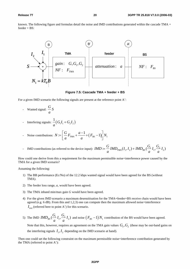
known. The following figure and formulas detail the noise and IMD contributions generated within the cascade TMA + feeder + BS:
TMA feeder BS
+
B B’ A’
1 2: , ,: TMA
gain G G GNF F
1I2I
1 0N kT B=
S : BSNF F:attenuation a
TMA feeder BS
+
B B’ A’
1 2: , ,: TMA
gain G G GNF F
1I2I
1 0N kT B=
S : BSNF F:attenuation a
Figure 7.5: Cascade TMA + feeder + BS
For a given IMD scenario the following signals are present at the reference point A’:
- Wanted signal: G Sa
- Interfering signals: ( )1 1 2 21 G I G Ia
+
- Noise contributions: ( ) 11: 1TMA BS
G aN F Fa a
−⎡ ⎤= + + −⎢ ⎥⎣ ⎦N
- IMD contributions (as referred to the device input): 1 21 2 1 2: ( , ) ( ,TMA BS
G GG )IMD IMD I I IMD I Ia a
= +a
How could one derive from this a requirement for the maximum permissible noise+interference power caused by the TMA for a given IMD scenario?
Assuming the following:
1) The BB performance (Ec/No) of the 12.2 kbps wanted signal would have been agreed for the BS (without TMA).
2) The feeder loss range, a, would have been agreed.
3) The TMA inband min/max gain G would have been agreed.
4) For the given IMD scenario a maximum desensitisation for the TMA+feeder+BS receive chain would have been agreed (e.g. 6 dB). From this and 1,2,3) one can compute then the maximum allowed noise+interference
testI (referred here to point A’) for this scenario.
5) The IMD 1 21( ,BS
G G2 )IMD I I
a a and noise ( ) 11BSF − N contribution of the BS would have been agreed.
Note that this, however, requires an agreement on the TMA gain values (these may be out-band gains on
the interfering signals 1 2,G G
1 2,I I depending on the IMD scenario at hand).
Then one could set the following constraint on the maximum permissible noise+interference contribution generated by the TMA (referred to point A’):
3GPP
3GPP TR 25.818 V7.0.0 (2006-03)21Release 7T
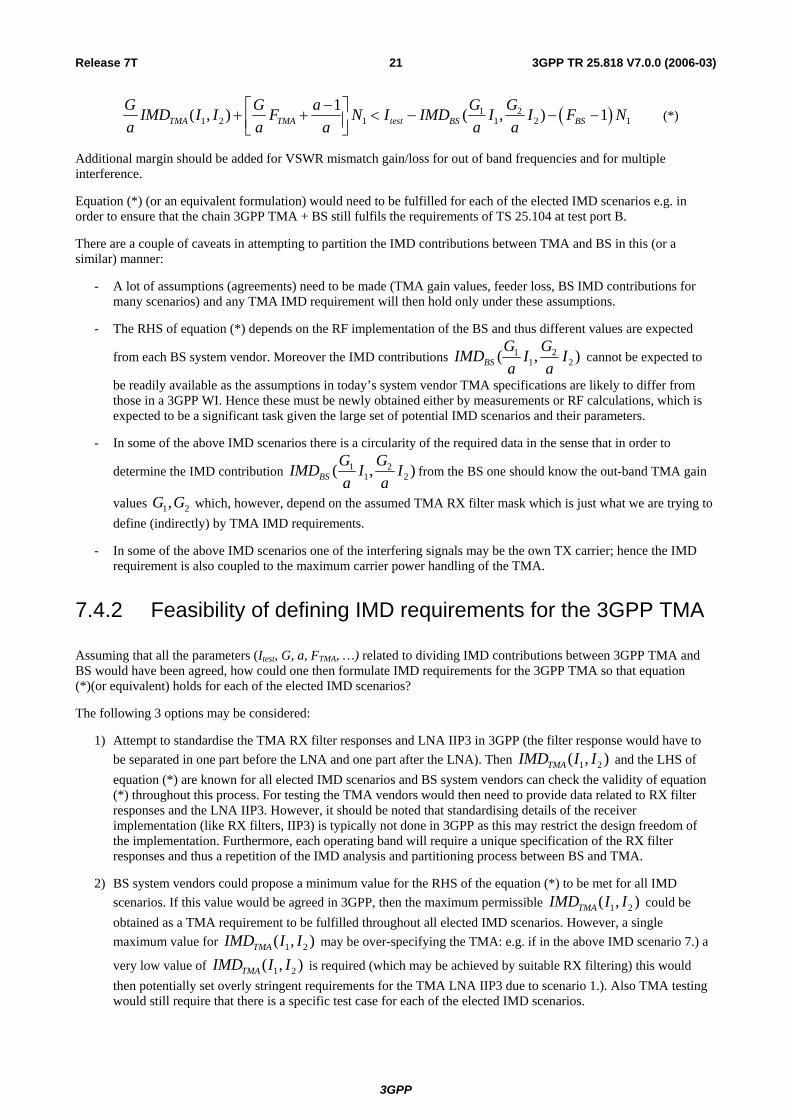
( )1 21 2 1 1 2 1
1( , ) ( , ) 1TMA TMA test BS BSG GG G aIMD I I F N I IMD I I F N
a a a a a−⎡ ⎤+ + < − − −⎢ ⎥⎣ ⎦
(*)
Additional margin should be added for VSWR mismatch gain/loss for out of band frequencies and for multiple interference.
Equation (*) (or an equivalent formulation) would need to be fulfilled for each of the elected IMD scenarios e.g. in order to ensure that the chain 3GPP TMA + BS still fulfils the requirements of TS 25.104 at test port B.
There are a couple of caveats in attempting to partition the IMD contributions between TMA and BS in this (or a similar) manner:
- A lot of assumptions (agreements) need to be made (TMA gain values, feeder loss, BS IMD contributions for many scenarios) and any TMA IMD requirement will then hold only under these assumptions.
- The RHS of equation (*) depends on the RF implementation of the BS and thus different values are expected
from each BS system vendor. Moreover the IMD contributions 1 21( ,BS
G G2 )IMD I I
a a cannot be expected to
be readily available as the assumptions in today’s system vendor TMA specifications are likely to differ from those in a 3GPP WI. Hence these must be newly obtained either by measurements or RF calculations, which is expected to be a significant task given the large set of potential IMD scenarios and their parameters.
- In some of the above IMD scenarios there is a circularity of the required data in the sense that in order to
determine the IMD contribution 1 21( ,BS
G G2 )IMD I I
a afrom the BS one should know the out-band TMA gain
values which, however, depend on the assumed TMA RX filter mask which is just what we are trying to define (indirectly) by TMA IMD requirements.
1,G G2
- In some of the above IMD scenarios one of the interfering signals may be the own TX carrier; hence the IMD requirement is also coupled to the maximum carrier power handling of the TMA.
7.4.2 Feasibility of defining IMD requirements for the 3GPP TMA Assuming that all the parameters (Itest, G, a, FTMA, …) related to dividing IMD contributions between 3GPP TMA and BS would have been agreed, how could one then formulate IMD requirements for the 3GPP TMA so that equation (*)(or equivalent) holds for each of the elected IMD scenarios?
The following 3 options may be considered:
1) Attempt to standardise the TMA RX filter responses and LNA IIP3 in 3GPP (the filter response would have to be separated in one part before the LNA and one part after the LNA). Then 1 2( , )TMAIMD I I and the LHS of equation (*) are known for all elected IMD scenarios and BS system vendors can check the validity of equation (*) throughout this process. For testing the TMA vendors would then need to provide data related to RX filter responses and the LNA IIP3. However, it should be noted that standardising details of the receiver implementation (like RX filters, IIP3) is typically not done in 3GPP as this may restrict the design freedom of the implementation. Furthermore, each operating band will require a unique specification of the RX filter responses and thus a repetition of the IMD analysis and partitioning process between BS and TMA.
2) BS system vendors could propose a minimum value for the RHS of the equation (*) to be met for all IMD scenarios. If this value would be agreed in 3GPP, then the maximum permissible 1 2( , )TMAIMD I I could be obtained as a TMA requirement to be fulfilled throughout all elected IMD scenarios. However, a single maximum value for 1 2( , )TMAIMD I I may be over-specifying the TMA: e.g. if in the above IMD scenario 7.) a
very low value of 1 2( , )TMAIMD I I is required (which may be achieved by suitable RX filtering) this would then potentially set overly stringent requirements for the TMA LNA IIP3 due to scenario 1.). Also TMA testing would still require that there is a specific test case for each of the elected IMD scenarios.
3GPP
3GPP TR 25.818 V7.0.0 (2006-03)22Release 7T
3) In order to be able to optimise the LNA cost, it is likely that a whole set of IMD requirements is required, rather than a single maximum IMD figure as in 2. BS system vendors could propose for each elected IMD scenarios a value for the RHS of the equation (*) to be met by the TMA. Also here TMA testing would require that there is then a specific test case for each of the IMD scenarios.
Testability of options 2.) and 3.) also require further study as the expected IMD powers will be close to the noise levels and furthermore, as the testing methodology of TS 25.141 based on the BLER of a reference measurement channel in the presence of interference cannot be assumed for the TMA.
Whatever the chosen method defining IMD requirements for the 3GPP TMA in the end may be, it should be equally applicable to all frequency Bands (i.e. also bands other than Band I), in order to be able to generate coherent 3GPP TMA specifications.
7.4.3 Summary of the feasibility of splitting the radio requirements between base station and 3GPP TMA
As shown, there are a large number of TMA radio parameters whose permissible values will depend on the detailed RF characteristics and performance of the BS to be supported. The most critical TMA radio parameters are:
1) Nominal RX passband gain (depends on BS gain distribution and receiver linearity)
2) Out-band gain mask (depends on BS gain distribution and receiver linearity)
3) IMD requirements (depends on BS receiver linearity)
4) Maximum power handling (depends on BS TX characteristics and configurations)
5) EVM on RX/TX paths (depends on BS EVM budget (filtering, clipping), this is relevant for frequency bands with narrow duplex gap)
Dividing these radio parameters between TMA and BS is non-trivial and will require a lot of detailed investigations for the TMA+BS receive (transmit) chain. E.g., in order to derive the TMA IMD requirements a potentially large set of data
points, (for 1 21( ,BS
G G2 )IMD I I
a a, see above) will be required from the BS system vendors.
Furthermore, there seems to be no other way in setting TMA IMD requirements than specifying either the details of the TMA receiver implementation (filters, IIP3) or having a large number of IMD test cases.
8 Impact on current specifications
8.1 Impact on TS 25.104 This clause identifies the impact on TS 25.104 when standardizing external low noise Tower Mounted Amplifier (TMA) in Rx for UTRA FDD
8.1.1 TMA standardisation alternative 1 It was stated in clause 7.1.2 that different characteristics of the BS+TMA chain at test port B’ should be avoided and in that sense the TS25.104 should not be affected.
8.1.2 TMA standardisation alternative 2 It was stated in clause 7.1.3 that the chain of 3GPP BS and 3GPP TMA will meet the performance requirements to be specified for the new test port B* in TS25.104. Since test port B* is achieved by placing the TMA in front of the 3GPP BS, complying to test port A, the behaviour at test port B* would be different compared to test port B characteristics of today.
3GPP

3GPP TR 25.818 V7.0.0 (2006-03)23Release 7T
- A number of high level performances aspects (e.g inband blocking, IMD,…) of the receiver will detoriate due to the gain and non-linearities in the TMA.
- Sensitivity performance of the receiver could be expected to be better due to the gain in the TMA.
- Some requirements of the receiver and transmitter will be detoriated due to phase distortion in the TMA filters.
8.1.3 TMA standardisation alternative 3 It was stated in clause 7.1.4 that a new 3GPP BS type to be operated with 3GPP TMA only is to be specified by new requirements in TS25.104 with test port A* as a seperate unit. This BS would have to have new performance requirements compared to any BS in TS25.104 today.
- A number of high level performance requirements of the receiver will have to be changed (i,e. dynamic range and possibly increase in receiver linearity) to cope with the gain and non-linearities in the TMA. The impact on these requirements will depend on the split of RF performance between BS and TMA.
- Sensitivity performance of the receiver could be expected to be better due to the gain in the TMA.
- Some requirements of the receiver and transmitter might have to be more stringent to allow for phase distortion in the TMA filters.
It was also stated in clause 7.1.4 that the chain of 3GPP BS and 3GPP TMA shall meet the performance requirements for test port B in TS25.104, but that it depends on the outcome of the partitioning between the 3GPP TMA and BS if it is possible.
8.1.4 General Today some operators and vendors have more stringent requirements than TS25.104, e.g. for blocking when GSM and WCDMA are collocated. Taking that into account this would mean additional impact on TS25.104 for alternatives 1 and 3.
8.2 Impact on TR 25.942 This clause identifies the impact on TR 25.942 when standardizing external low noise Tower Mounted Amplifier (TMA) in Rx for UTRA FDD.
8.2.1 TMA standardisation alternative 1 If TS25.104 is not affected, which would be the goal according to clause 8.1.1, the TR25.942 will not be affected either. If TS25.104 is affected also TR25.942 will be affected but it is difficult to predict the impact on TR25.942 before the impact on TS25.104 is known.
8.2.2 TMA standardisation alternative 2 As stated in clause 8.1.2 all high level requirements of the receiver would be deteriorated due to the gain in the TMA and the phase distortion in the filters might impact performance of both the receiver and transmitter. TR25.942 would be heavily impacted taking all new characteristics into account.
8.2.3 TMA standardisation alternative 3 If TS25.104 is not affected, which would be the goal according to clause 8.1.3, the TR25.942 will not be affected either.
8.3 Impact on Radio Resource Management requirements This clause identifies the impact on RRM requirements when standardizing external low noise Tower Mounted Amplifier (TMA) in Rx for UTRA FDD.
3GPP

3GPP TR 25.818 V7.0.0 (2006-03)24Release 7T
If a BS is equipped with TMA, the reference point for UTRAN measurements with reference point at “antenna connector” shall be the antenna connector of the TMA. This is already the case for BS equipped with a TMA provided by the BS manufacturer and shall also apply to BS with TMA analyzed in the present TR.
UTRAN measurements performed in the BS are impacted by the gain and delay in the RX path of the TMA and insertion loss and delay in the TX path of the TMA. The feeder loss between BS and TMA also need to be considered. Therefore, the BS needs knowledge of the following system parameters in order to adjust their measurements with respect to the reference point at the TMA antenna connector:
- TMA gain in each RX path
- TMA delay in each RX path
- TMA loss in each TX path
- TMA delay in each TX path
- Feeder loss and delay between BS and TMA (for the actual site installation).
The way how these parameters (except feeder loss and delay) are provided to the BS is ffs.
Beside the absolute values of the parameters above also their accuracy (over frequency, temperature, time) is of interest as this impacts the accuracy of UTRAN measurements as specified in TS25.133. The impact of variation of these parameters on UTRAN measurement accuracy needs to be studied to derive corresponding parameter accuracy limits – if this turns out to be not viable the measurement accuracy needs to be revised in accordance with the assumed TMA parameters and their accuracy.
9 Conclusion This clause lists the conclusions of the study on different alternatives how external low noise RX amplifier radio requirements for UTRA FDD could be standardized.
The feasibility of standardizing the BS – TMA interface has been studied in this TR regarding the following key aspects:
1) Feasibility of splitting the radio requirements between BS and TMA
2) Feasibility of standardization alternatives, including conformance testing and system responsibilities
3) Impact on Radio Resource Management requirements.
Regarding aspect 1) it was observed that a number of radio performance related parameters would need to be split between BS and TMA. No meaningful TMA specification can be developed without such a radio parameter split, as otherwise there would be no defined performance for the BS+TMA chain. However, this parameter split is non-trivial and would need to be reconsidered for each operating band and for each TMA gain alternative. This would require detailed investigations for the TMA+BS receive / transmit chain in a possible WI.
In particular, for deriving the TMA IMD requirements a set of interference scenarios would need to be considered and their respective IMD levels would need to be agreed and split between the BS and TMA. Furthermore, there seems to be no other way in setting TMA IMD requirements than specifying either the details of the TMA receiver implementation (RX filters, IP3) or having a number of IMD test cases.
There exist different options for the split of the performance between the BS and the TMA. That is true not only for the TMA gain but also for linearity in the TMA amplifier as well as the filtering in the TMA. In order to cope with all different solutions the TMA would have to fulfill the worst case scenario or the base station requirements would have to be tightened for some vendors to be compatible with all TMAs. This would either drive the cost for the TMA or the base stations or it would be a solution with a lot of options which would not guarantee interoperability.
The feeder loss between BS and TMA also needs to be taken into account when defining the radio requirements for BS and TMA. Then any minimum performance requirements defined for the BS+TMA chain can only be ensured for the assumed range of feeder losses.
3GPP

3GPP TR 25.818 V7.0.0 (2006-03)25Release 7T
Regarding aspect 2), it was generally noted that the BS-TMA interface needs to be specified for both, the BS and TMA if the inter-working of BS and TMA of different vendors should be facilitated by 3GPP standards. Three standardization alternatives were considered in more detail in section 7 with the following observations:
1) In TMA standardisation alternative 1 the interface between BS and 3GPP TMA is not standardised, as minimum performance and conformance test requirements for the BS as a separate unit are not included. Hence it is not possible to replace the BS system vendors overall responsibility for the conformance testing and inter-working of the BS+TMA chain (as present in today’s situation) by the separate conformance of the BS and TMA to appropriate 3GPP BS-TMA interface standards. Furthermore, it is not evident, how the inter-working of the BS with any 3GPP TMA could be ensured by the BS system vendor without extensive conformance testing of the BS+TMA chain with candidate 3GPP TMAs. Summarizing, this standardisation alternative does not facilitate the interoperability of BS and TMA from different vendors in any significantly better way than today’s standards situation and is therefore not recommended for standardisation as the development of the TMA specifications alone would still require a substantial effort from RAN WG4.
2) In TMA standardisation alternative 2 the interface between 3GPP BS and 3GPP TMA would be standardized, but the requirements are not properly matched, as retaining the current test port A requirements for the BS does not cover the 3GPP TMA over-gain alternatives. Consequently, the currently specified performance requirements at test port B will not be attainable for the BS+TMA chain. However, as these are core performance requirements, this alternative is not seen as acceptable for standardisation. Changing core requirements in alternative 2 would change system performance and would require substantial amount of the system analysis work to be redone. In addition it might possibly violate regulatory requirements and is therefore not seen as acceptable.
3) In TMA standardisation alternative 3 the interface between BS and TMA would be standardized by introducing a new set of requirements at test port A* for a new BS type to be operated with a 3GPP TMA only. If both, the BS and the TMA are separately conformance tested there should be no need for the chain of BS and TMA to be conformance tested and interoperability could be guaranteed by 3GPP standards design rather than by the BS system vendor. The scope of the A* radio requirements is expected to be comparable, but not identical to the current test port A requirements. The TMA standardization will either require to standardize details of the TMA implementation or to standardize a number of TMA IMD characteristics among other things. Standardizing details of the TMA implementation will restrict design freedom and in the long term drive TMA cost. Standardizing a number of TMA IMD characteristics is non-trivial both from characterization and testing. Each operating band and each alternative TMA gain value requires a reconsideration of the split of the radio parameters between TMA and BS and a separate set of minimum performance and conformance test requirements at test port A*. Therefore this alternative does require a significant amount of standardization work in order to develop the detailed specifications at test port A* as well as for the TMA.
As a summary the following can be stated: - Alternative 1: Not a standardized solution at all, meaning that it does not allow nor guarantee interoperability
and therefore does not make sense for vendors or operators.
- Alternative 2: Jeopardizes overall system performance and might even violate regulatory requirements and is therefore not acceptable.
- Alternative 3: A multiple set of radio parameters has to be split between different BS and TMA implementations, for all considered frequency bands. That means a non-trivial work which requires a considerable amount of standardization work, which seems difficult to handle within a reasonable WI time plan. This would either be a solution with a number of noninteroperable options or drive the cost for the TMA or the base stations.
Finally, it should be noted that the impact on TMA radio requirements related to antenna feeder sharing with other systems (e.g. GSM in Band VIII) was outside the scope of the SI. This configuration is even more complex and would require further analysis, but the conclusions drawn in the SI still apply.
3GPP

3GPP TR 25.818 V7.0.0 (2006-03)26Release 7T
Annex A: Change history
Change history Date TSG # TSG Doc. CR Rev Subject/Comment Old New
2005-08 WG4#36 R4-050656 TR created 0.0.12005-11 WG4#37 R4-051440 Documents included: R4-051150, R4-051161,
R4-051267, R4-051268, and R4-051427. 0.0.2
2006-02 WG4#38 R4-050325 Documents included: R4-060009, R4-060010, R4-060323, R4-060073 and R4-060324.
0.0.3
2006-03 RAN#31 RP-060056 For approval to RAN. 2.0.02006-03 RAN#31 Approved and put under change control 2.0.0 7.0.0
3GPP