Embed Size (px)
Citation preview

AC SERVO MOTOR
OPERATION MANUAL
MODEL : H V P – 90 SERIES
HSVP90U01 - EN 2005. 08
ENGLISH

1. Safety Precautions ………………………………………………………………………………
2. Installation and Adjustment 2.1 Motor installation …………………………………………………………………………………… 2.2 Installation diagram ………………………………………………………………………………… 2.3 Adjustment on the belt cover ………………………………………………………………………… 2.4 Install and adjust the synchronizer …………………………………………………………………… 2.5 Speed control unit adjustment …………………………………………………………………………
3. Power Connection and Grounding 3.1 Single phase and three phase connection …………………………………………………………… 3.2 Connect a 1Φ / 220 V power from a 3 Φ / 380 V power source ………………………………… 3.3 The load balance for 1Φ / 220 V motors used on a 3 Φ / 220 V power source ………………… 3.4 How to change solenoid supply voltage (DC: 24 V OR 30 V) ……………………………………
4. 7-Segment LED Display Mode and Function Keys : 4.1 Normal mode display …………………………………………………………………………………
4.2 Panel function keys adjustment ……………………………………………………………………
5. General Parameter Adjustment 5.1 How to enter each parameter mode ………………………………………………………………
5.2 How to enter parameter value area and make adjustment …………………………………………
5.3 Machine code adjustment ………………………………………………………………………………
5.4 General function parameter ……………………………………………………………………………
6. Operation Box
6.1 C-60M / C-300M Operation box keys definition …………………………………………………… 6.2 C-60M parameter adjustment ………………………………………………………………………
7. Error Code / Basic Trouble Shooting Error code and measurement ……………………………………………………………………………
8. General Parameter List 10.1【Parameter Mode A】list ………………………………………………………………………… 10.2【Parameter Mode B】list …………………………………………………………………………
Appendix A : Connector Panel 1. HVP-90- 4 -7W ………………………………………………………………………………………… 2. HVP-90- 4 –BR (T8) ……………………………………………………………………………………
3. HVP-90- 4-11 (Y6) ………………………………………………………………………………………… 4. HVP-90- 4 -66 (07)、(V7)、(V8) ………………………………………………………………………
5. HVP-90- 4 -98 ………………………………………………………………………………………… 6. HVP-90- 4 –DW (46) (LT) …………………………………………………………………………………
Bottom page: 7-segment display characters compare chart
MODEL : HVP - 90 SERIESCONTENTS
Page 1
2
2
3
3
3
4
4 5
5
6
6
7
7
7
8
9
12
13
14 16
A
A
B B C
C

1
1. Safety Precaution
Please read this manual carefully , also with related manual for the machine head before use. For perfect operation and safety, installing and operating this product by trained personnel is required. Also the following precaution must be taken. . ․Turn off the power, unplug the cord and wait 10 minutes before any installing, mounting, or opening the
control box cover.
․This product is designed for use with specified sewing machines and must not be used for other purposes.
․Only use Power Voltage indicated on the name plate of the HVP-90 in 土 10 % ranges.
․To avoid the false operation, please keep the product away from the high electromagnetic machinery or
electro pulse generator.
․Don’t operate in direct sun light、outdoors area and the room temperature is 45°C above or 5°C under.
․Don’t operate near the heater、dew area and the humidity is 30 % less or 95% more.
․Don’t operate in dusty、evaporate、combustible gas area, and stay away from corrosive material.
․Avoid power cord being applied by heavy objects or excessive force, or over bend.
․Power cord must keep 3 cm or above distance to the V-belt and the pulley.
․To avoid the static interference and current leakage, all grounding must be done correctly.
․Use the correct connector and extension wire when connecting ground wire to Earth and secure it tightly.
․Turning on the machine in the first time, use low speed to operate and check the correct rotation direction.
․During machine operation, don’t touch any moving parts.
․All moving parts must use the protective device to avoid the body contact and objects insertion.
․Maintenance and repairs must be done by the specially trained personnel.
․Don’t cover up motor’s ventilation, it can cause motor overheated.
․Don’t use any objects or force to hit or ram the product.
․All spare parts for repair must be approved or supplied by the manufacturer.
Danger and caution signs :
Risks that may cause personal injury or risk to the machine are marked with this symbol in the instruction manual.
This symbol indicates electrical risks and warnings.
Warranty information : Manufacturer provide a warranty in respect of the products covered for a period of 1
year use or 1 year and 6 months after the shipping date of the products for any defects arising in the normal course of use of the products by customers.

- 2 -
2. Installation and Adjustment: 2.1 Motor installation : (Recommend table drill holes) 2.2 Installation diagram:
a). Install the motor and control box under the table b).Install the pedal with speed control unit c). Install the V-Belt
For USA Base
57
216
Oil tank
66 105
Drill 9 mm hole
table
For Cable
Drill 40 mm hole
70
tank
70
Oil
57
190
Oil tank
70 105
For Din Base
table
Drill 9 mm hole
1). Motor pulley and machine pulley must properly align.
2). Cable pass through or under the working table must be secured to avoid rubbing with the V-belt
3). Use the motor base to adjust belt’s tension.
Control Box
Motor
V-Belt
pedal
Motor Motor
pedal
* All connectors must plug well
Connector panel
Operation box & synchronizer
Motor connector
Power input
7 pins synchronizer
Operation box
Speed control unitControlBox
ControlBox
Control panel

- 3 -
2.3 Adjustment on the belt cover:
2.4 Install and adjust the synchronizer (sensor):
a). Synchronizer installation:Mounting the Synchronizer onto the flange of machine pulley and fasten the rotor by setting screws. b). Synchronizer adjustment:
Needle up position : Rotate the machine pulley to reach mechanical needle up position and turn the photo plate (A) until its red mark is aligned with the red mark on the bearing cover plate.
Needle down position : Rotate the machine pulley to reach mechanical needle down position and turn the photo plate (B) until its blue mark is aligned with the red mark on the bearing cover plate.
Note: instruction above is the standard adjustment. If you feel the position wasn’t accurate, please do the fine tuning by yourself.
2.5 Speed control unit adjustment :
Components of speed control unit : see figure A: Spring for toeing forward force adjustment B: Bolt for heeling backward force adjustment C: Treadle / Pedal arm D: Pitman rod for Treadle / Pedal
Caution :
Turn OFF the power, before
making the adjustment.
Setting screw
Bearing cover plate
Photo Plate (A)
Photo Plate (B)
. . .
a). Adjust the belt stopper (A) properly and leave about 5~10 mm space from V-belt. b). Factory default, finger guard is set at position (B). (for rotation of counterclockwise)
For rotation of clockwise, the finger guard must be moved to position (C) and avoiding contact to the V-belt or pulley.
Term of adjustment
Toeing forward force adjustment
Heeling backward force adjustment
Treadle stroke adjustment
Adjustment result
Spring A move to right = force increased
Spring A move to left = force decreased
Bolt B turn = force decreased
Bolt B turn = force increased
Rod D secure at right = stroke is longer,
Rod D secure at left = stroke is shorter。
1
2
3
B
A
C
D
increase decrease
decrease increase
B
Belt stopper
Finger guard (CE type only)
C
A

- 4 -
3. Power Connection and Grounding: 3.1 Single phase and three phase connection:
Green/yellow wire is the ground wire.
3.2 How to connect a 1Φ / 220 V power from a 3 Φ / 380 V power source
1. When a three phase 220 V servo motor use a single phase 200 ~ 240 V power source, only connect brown and blue wires. Use insulating tape to wrap up the unused black wire, in order to prevent the current leakage.
2. Green / Yellow wire must do the grounding.
Caution:If the power source have no neutral point, then this servo motor is not suitable for this connection.
R
S
T
N
PEGrounding system G G G
1ψ220V Motor
1ψ220V Motor
1ψ220V Motor
L1 L1 L1
L2
L2
L2
Neutral
Caution: Must have a neutral point
380 V 380 V 220 V
220 V 220 V
380 V
Single Phase
Brown wire
Blue wire
Green/Yellow wire
Three Phase
Brown
Black
Blue
Green / Yellow
To control box
If use a single phase power(220 V), don’t connect the black wire.
OFF ON
OFF ON
To control box

- 5 -
3.3 The load balance for 1Φ / 220 V motors used on a 3 Φ / 220 V power source. See the following figure for the load balance.
3.4 How to change solenoid supply voltage (DC: 24 V OR 30 V): The JP1 is for 30 V and JP2 is for 24 V.
Caution 1: Before making the switch, check the machine head’s Solenoid specification.
Caution 2: Turn off the power and wait for 10 min.
before opening the cover.
High Voltage inside
24 V jumper setting 30 V jumper settingStep 2
Step 1
R S T
HSV-PS1122007
C 70C 8 C 9
15 W 10Ω
CT1
CT2
JP1JP2
The power board layout :
JP 1 30 V
JP 2 24 V
JP 1 30 V
JP 2 24 V
Remove 2 screws

- 6 -
4. 7-Segment LED Display Mode and Function Keys : 4.1 Normal mode display :
Power ON = Normal mode : See the diagram for lockstitch machine and interlock stitch machine display.
4.2 Panel function keys adjustment :
Lockstitch machine functions
Select bar tacking function, LED show . Press key to adjust the stitches and times Select constant stitch sewing, LED show . Press key to adjust the stitches and sections.
Select start / back tacking, LED show . Press key to adjust the stitches.
Function selection, LED above the key lighten means function enabled.
Interlock stitch machine functions
Special functions selection: A = half heeling、B = trimming、C = wiping、D = start constant stitch sewing. Press any of A、B、C key, the icon show up which mean the corresponding function been disable. Except the D key, the icon
show up which mean the start constant stitch sewing been enable.
Interlock stitch machine
Lockstitch machine
STOP
P S
A B C D
.
Enter parameter / Parameter increment Free sewing、Bar tacking、Constant stitch sewing / Enter parameter value / Saving Start back tacking / Parameter increment End back tacking / Parameter decrement Needle up at machine stop. Soft start
Presser foot up at machine stop
Presser foot up after trimming.
7-segament LED. Setting key for Number of stitches / Number of sections / Number of times
STOP
P S
A B C D
.
Enter parameter / Parameter increment Enter parameter value / Saving Parameter increment Parameter decrement Needle up at machine stop. Soft start
Presser foot up at machine stop
Presser foot up after trimming.
7-segament LED.
Special function keys
. . A B C D
A B C D.. . A B C D

- 7 -
5. General Parameter Adjustment :
5.1 How to enter each parameter mode :
5.2 How to enter parameter value area and make adjustment : Step 1 : Enter the parameter level and find the parameter.
Step 2 : After find the parameter, press the key to enter the parameter value area. Press any of
key to adjust the parameter value.
5.3 Machine code adjustment : Machine code 047. MAC: Enter the parameter level 2, the first parameter is the machine code.
Then press the key to enter the parameter value area. Press A、B、C、D key to adjust the machine code.
After adjustment press the key to save the setting.
Parameter mode Operating method First display Keys Range of parameter
Level 1 【Mode A】
# 001 ~ 046
Level 2 【Mode B】
# 001 ~ 122
S
S
S
A B C D
.
.
At【Normal mode】
Press key P
P Turn-on power
Terms for A、B、C、D keys in the parameter value::
VALUE TERMS
KEY別
IN TERMS OF SPEED 1000 spm 100 spm 10 spm 1 spm
IN TERMS OF ANGLE -------- 100 ° 10 ° 1 °
IN TERMS OF TIMING 1000 ms 100 ms 10 ms 10 ms
IN TERMS OF FUNCTION FUNCTION SWAP FUNCTION SWAP
∴ Other than the function selection, each press of the key will start change the value from 1 to 10
A B C D
Note: After value changed, press the key to save the value, otherwise they will lost after turning power off.S
Note : 1. The【047.MAC】machine code setting might be varies which depends on the machine head brand and model
2. Wrong machine code setting might cause machine head operation abnormal or damaged.
3. After save the machine code, the corresponding parameters will load the default value automatically.

- 8 -
5.4 General function parameter : Follow the steps on section 5.1、5.2 to adjust the these parameters
Speed function
【 001. H 】 Maximum sewing speed ( spm )
【 004. N 】 Start back-tacking speed ( spm )
【 005. V 】 End back-tacking speed ( spm )
【 006. B 】 Bar-Tacking Speed ( spm )
【 007. S 】 Soft start speed ( spm )
【 009. A 】 Automatic constant-stitch sewing speed ( spm )
【 122. H L 】 Upper limit of maximum speed ( spm )
Back tacking
【 014. S B T 】 Start back-tacking function selection
【 015. S B A 】 Setting stitches A of Start back-tacking
【 016. S B B 】 Setting stitches B of Start back-tacking
【 017. S B N 】 Setting turns of Start Back-tacking
【 021. E B T 】 End back-tacking selection
【 022. E B C 】 Setting stitches C of End back-tacking
【 023. E B D 】 Setting stitches D of End back-tacking
【 024. E B N 】 Setting turns of End back-tacking
Bar tacking / Constant stitch
【 032. B A R 】 Bar-tacking selection
【 033. B R C 】 Setting stitches of Bar-tacking
【 034. B R N 】 Setting turns of Bar-tacking
【 010. A C D 】 Automatic sewing End back-tacking
【 038. P M】 Constant-stitch sewing selection
【 039. P S 】 Setting stitches for section of Constant-stitch sewing
Wiper / Trimmer
【 040. W O N】 Wiper function selection
【 092. W 1 】 Delayed timing prior to wiper engaged
【 093. W 2 】 Setting timing of wiping
【 041. T M 】 Trimmer function selection
【 082. T 1 】 Delayed timing prior to trimmer engaged
【 083. T 2 】 Trimming time Automatic presser foot
【 064. FO 】 Full-On time setting for foot lifting solenoid
【 065. FC 】 Duty cycle time setting for foot lifting solenoid
【 066. FD 】 Running-Delay time setting
【 070.HHC 】 Cancel foot lifting at half-heeling pedal
NOTE: 1. When motor running, the parameter area is locked and prohibited for access. The
parameter only can be adjust when motor stop 2. When press the key to access parameter area, the key can also act as
the parameter increment key. 3. When adjust the parameter, you must fully understand the function usage and the
setting effects. If you have doubt or question, pleas ask the customer service or technical support to help you. Don’t try to adjust blindly.
4. Caution! Wrong setting of the parameter might cause the abnormal operating and damage the sewing machine.
P P

- 9 -
6. Operation Box :
Function KEY Operation of Sewing Machine
Double start back tacking (A,B sections)
Single start back tacking (A,B sections)
Half start back tacking (B section ) (C-60M)
Double end back tacking (C,D sections)
Single end back tacking (C,D sections)
Start / End back tacking
selection
Half end back tacking (C section) (C-60M)
Constant stitch sewing
1). When the treadle is toeing down, constant-stitch sewing E、F、G or H performed section by section.
2). If the treadle returns to neutral intermediately in any one section, the machine will stop immediately. After the treadle toed down again, the balanced stitches of E、F、G or H goes on.
3).If the parameter【010. ACD】is set ON, the machine will not stop and automatically start trimming cycle and end back tacking at the end of the last section E or H.
4).When use P1~PF function, P1~P4 default setting is 15 stitches, other unused sections must set 0 stitch.
6.1 C-60M / C-300M Operation box keys definition : (C-300M don’t have parameter setting function)
C−60FE
SPG H
A B C D
M
C−300M
E
A B
F
DC
HG
- 10 -
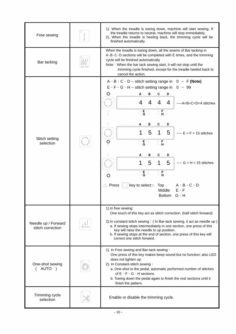
Free sewing
1). When the treadle is toeing down, machine will start sewing. If
the treadle returns to neutral, machine will stop immediately. 2). When the treadle is heeling back, the trimming cycle will be
finished automatically.
Bar tacking
When the treadle is toeing down, all the seams of Bar tacking in A、B、C、D sections will be completed with E times, and the trimming cycle will be finished automatically Note:When the bar tack sewing start, it will not stop until the
trimming cycle finished, except for the treadle heeled back to cancel the action.
Stitch setting selection
A、B、C、D -- stitch setting range in 0 ~ F (Note) E、F、G、H -- stitch setting range in 0 ~ 99
----A=B=C=D=4 stitches
---- E = F = 15 stitches
---- G = H = 15 stitches
∴ Press key to select : Top A、B、C、D Middle E、F Bottom G、H
Needle up / Forward stitch correction
1).In free sewing: One touch of this key act as stitch correction. (half stitch forward)
2).In constant-stitch sewing:( In Bar-tack sewing, it act as needle up ) a. If sewing stops intermediately in one section, one press of this
key will raise the needle to up position. b. If sewing stops at the end of section, one press of this key will
correct one stitch forward.
One-shot sewing ( AUTO )
1). In Free sewing and Bar-tack sewing: One press of this key makes beep sound but no function; also LED does not lighten up.
2). In Constant-stitch sewing: a. One-shot to the pedal, automatic performed number of stitches
of E、F、G、H sections. b. Toeing down the pedal again to finish the rest sections until it
finish the pattern.
Trimming cycle selection
Enable or disable the trimming cycle.
4 4 4 4
1 5 1 5
1 5 1 5
FEG H
A B C D
FEG H
A B C D
FEG H
A B C D

- 11 -
Soft start (C-60M)
1).When function turn on, soft start only activated at first run of motor start. After trimming cycle finish, it will be activated again on next motor start.
2). Speed of the soft start can be set by parameter [007. S]. 3). Number of stitches can be set by parameter [008.SLS].
Needle up / down when motor stop
(C-60M)
Needle stop setting LED ON= Stop at up position LED OFF=Stop at down position
Presser foot up / down after trimming cycle
(C-60M)
Presser foot action after trimming LED ON= Automatic lift the presser foot after trimming LED OFF=Presser foot not active after trimming..
Presser foot up / down when motor stop
(C-60M)
Presser foot action when motor stop LED ON=Motor stop, presser foot goes up automatically. LED OFF=Presser Foot not active when motor stop.
Value increment key
A、B、C、D section value increment key, range in 0~ F.(Note) E、F、G、H section value increment key, range in 0~99.
Value decrement key
A、B、C、D section value decrement key, range in 0~ F.(Note)E、F、G、H section value decrement key, range in 0~99.
Enter parameter area / Parameter increment
(C-60M)
Press and hold this key for 2 second to enter parameter area. Also act as parameter increment key
Enter parameter value / Saving
(C-60M)
Press this key in parameter area to enter parameter value area. Also act as the parameter value saving key.
P
S
Note : Stitches setting of A、B、C、D sections correspond to the alphabet. A=10、B=11、C=12、D=13、E=14、F=15 stitches

- 12 -
6.2 C – 60M parameter adjustment : 6.2.1 How to access【Parameter Mode A】 ……… parameters total from 001~046
6.2.2 How to access【Parameter Mode B】 ……… parameters total from 047~122
6.2.3 Terms for C-60M in parameter value:
a. In【Normal mode】area, press key to access the mode A P
OFF ON
a. If machine ON, Power OFF first. b. Press and hold key and turn on the power to access the first parameter
code【 047.MAC 】of【parameter mode B 】 P
FE
SPG H
A B C D
OFF ONFE
SPG H
A B C D
FE
SPG H
A B C D
Note: After press key to save the
value, it also automatic go back to
normal mode
S
a. Hold for 2 sec.
b. Use or key to find the parameter 【 002. PSL 】
c. Use key to access【value area】S
d. Use the key under the
area to set the value.
e. press key to save the value.
A B D C S
FE
SPG H
A B C D
c. Access
b. Select
FE
SPG H
A B C D
e. Save
d. Adjust
FE
SPG H
A B C D
d. Access
c. Select
FE
SPG H
A B C D
f. Save
e. Adjust
FE
SPG H
A B C D
Go back to normal mode
. . .
.
.
. .
Terms for A、B、C、D area which adjust by the key in the parameter value.
Note : 1. After value changed, press the key to save the value, otherwise they will lost after turning power off. 2. Under the parameter mode, the function keys are invalid.
S
Value Terms
Key
IN TERM OF SPEED 1000 spm 100 spm 10 spm 1 spm
IN TERM OF ANGLE -------- 100 ° 10 ° 1 °
IN TERM OF TIMMING 1000 ms 100 ms 10 ms 10 ms
IN TERM OF FUNCTION Mode selection
∴ Other than the mode selection, each press the or key will circling the value from 0 to 9, the total value can’t be set lower or greater than the ranged value. When the value is the maximum ranged value, press any key of the A、
B、C、D area will change the value back to the minimum ranged value.
A B C D
b. Use or key to find the parameter 【 048. N12 】
c. Use key to access【value area】 S
d. Use the key under the
area to set the value.
e. press key to save the value.
A B D C S

- 13 -
7. Error Code / Basic Trouble Shooting : Error code and measurement :
Error Code Cause of the Problem Status and Measurement
ER0. 4 1. When power on, detected high voltage 2. Connect the wrong voltage, too high. 3. F2 fuse blown
Motor and machine will be shutting down. Please check the AC power. (Too high)
Please check the main board. Please check the F2 fuse.
ER0. 5 1. When power on, detected low voltage 2. Connect the wrong voltage, too low..
Motor and machine will be shutting down.. Please check the AC power. (Too low) Please check the main board.
ER0. 7 1. Bad connection at the motor connector. 2. Synchronizer (sensor) signal error.
3. Machine locked or object stuck in the motor pulley. 4. Sewing material is too thick.
Motor and machine will be shutting down. Please check the motor or motor connectors and its connection. Please check the synchronizer (sensor) and its signal. Please check the machine head to see if objects stuck in the motor pulley, or rotate not smoothly.
ER0. 8 Operation box linked to CPU interface had communication error Motor and machine will be shutting down. Please check the operation box.
ER0. 9 1. Machine solenoid shorted. 2. Main board’s power transistor is faulty.
Motor still can run, but all output signals and operation box pattern sewing function will be invalid.. Please check the machine’s solenoids or the resistance value is 2 Ω less. Please check all the power transistors which related to solenoid.
ER0. 11 1. If parameter 【121.ANU】 is set ON, but auto needle up is
malfunction when the power turned on. 2. Machine locked or motor pulley have object stuck in it.
Motor still can run, but it automatic starts the clutch mode. All constant-stitch sewing pattern and trimmer wiper function will be invalid.
Please check the synchronizer up position signal. Please check the main board’s synchronizer circuitry. Please check the machine head to see if objects stuck in motor pulley or rotate not smoothly.
Motor rotation icon in LED is halting and not moving. 1. Safety switch is either faulty or bad connection. (For interlock stitch
or blind stitch machine). 2. Parameter【075. SFM】setting not match the machine head model.
Motor stops. Please check the safety switch. Please check parameter setting on【075. SFM】and make sure it accord with machine head safety switch mode
.

- 14 -
8. General Parameter List : 8.1【Parameter Mode A】list Parameter Code Parameter Function Range / Selection Description
【 001. H 】 Maximum sewing speed ( spm ) 50 ~ 9999 Maximum speed adjustments
【 002. P S L 】 Speed curve adjustments ( % ) 1 ~ 100 % The speed up setting for the speed control unit. The larger the value the faster to up speed.
【 003. CNR】 Counter ratio selection 1 ~ 100 Setting the multiple to the value of 【042. CUD】
【 004. N 】 Start back-tacking speed ( spm ) 50 ~ 8000 Start back-tacking speed adjustments
【 005. V 】 End back-tacking speed ( spm ) 50 ~ 8000 End back-tacking speed adjustments
【 006. B 】 Bar-Tacking Speed ( spm ) 50 ~ 8000 Repeat bar-tacking speed adjustments
【 007. S 】 Soft start speed ( spm ) 50 ~ 2000 Soft start speed adjustments
【 008. S L S 】 Stitch numbers for soft start ( 針 ) 0 ~ 99 stitches Soft start stitches setting
【 009. A 】 Automatic constant-stitch sewing speed ( spm ) 50 ~ 8000
Valid only at the auto pattern sewing or one shot signal(SH)
active
【 010. A C D 】 Automatic sewing End back-tacking ON / OFF Only at the last seam of pattern sewing ON:Valid. OFF:Invalid.
【 011. R V M 】 Back-tacking mode selection J / B J = JUKI mode , B = BROTHER mode. J:Active when motor stop or running B:Active only when motor running
【 012. S M S 】 Back-tacking mode selection A / M / SU / SD
Start back-tacking mode selection : A:One shot sewing M:Pedal control and motor can stop at middle way. SU:One shot sewing but motor stops at needle up by
[027.CT] timer at end of each seam. SD:One shot sewing but motor stops at needle down by
[027.CT] timer at end of each seam.
【 013. T Y S 】 Mode selection at the end of Start back-tacking CON / STP / TRM
CON:At the end of Start back-tacking ,it continues sewing if pedal pressed or START signal on (standing operation)
STP:At the end of Start Back-Tacking, machine stops and must re-start by pedal command.
TRM:Making the trimming cycle once the Start Back-Tacking finished. ( Mini Bar tacking )
【 014. S B T 】 Start back-tacking function selection ON / OFF Valid only when the operation panel disconnected. ON:Perform OFF:Not perform
【 015. S B A 】 Setting stitches A of Start back-tacking 0 ~ 15 stitches
【 016. S B B 】 Setting stitches B of Start back-tacking 0 ~ 15 stitchesStart back-tacking stitches setting ,【014. SBT】= ON valid
【 017. S B N 】 Setting turns of Start Back-tacking 0 ~ 4 turns Setting the seam times of Start back-tacking ,【014. SBT】= ON valid
【 018. B T 1 】 Stitch balance for Start Back-tacking 1
【 019. B T 2 】 Stitch balance for Start Back-tacking 2 0~F
BT1=0:Invalid,1-8:Increase stitches of reverse seam, 9-F:Increase stitches of forward seam BT2=0:Invalid,1-8:Increase stitches of forward seam, 9-F:Increase stitches of reverse seam
【 020. S ME 】 Mode selection for End back-tacking A / SU / SD
End back-tacking mode selection. : A:One shot sewing. SU:One shot sewing but machine stops up position by
【027. CT】 timer at the end of each seam. SD:One shot sewing but machine stops down position by
【027. CT】 timer at the end of each seam.
【 021. E B T 】 End back-tacking selection ON / OFF Valid only when the operation panel disconnected. ON:Perform OFF:Not perform
【 022. E B C 】 Setting stitches C of End back-tacking 0 ~ 15 stitches
【 023. E B D 】 Setting stitches D of End back-tacking 0 ~ 15 stitchesEnd back-tacking stitches setting ,【021. EBT】 = ON valid
- 15 -
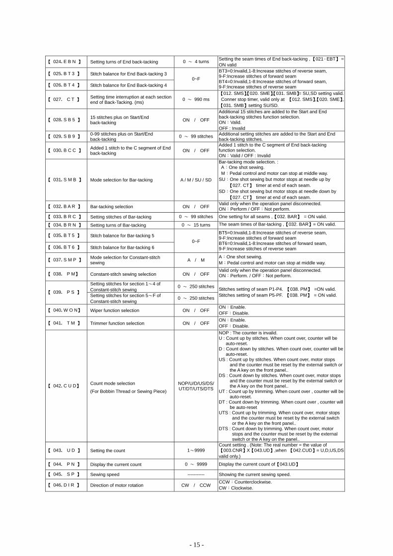
【 024. E B N 】 Setting turns of End back-tacking 0 ~ 4 turns Setting the seam times of End back-tacking , 【021.EBT】 = ON valid
【 025. B T 3 】 Stitch balance for End Back-tacking 3
【 026. B T 4 】 Stitch balance for End Back-tacking 4 0~F
BT3=0:Invalid,1-8:Increase stitches of reverse seam, 9-F:Increase stitches of forward seam BT4=0:Invalid,1-8:Increase stitches of forward seam, 9-F:Increase stitches of reverse seam
【 027. C T 】 Setting time interruption at each section end of Back-Tacking. (ms) 0 ~ 990 ms
【012. SMS】,【020. SME】,【031. SMB】= SU,SD setting valid.Conner stop timer, valid only at 【012. SMS】,【020. SME】,【031. SMB】setting SU/SD.
【 028. S B 5 】 15 stitches plus on Start/End back-tacking ON / OFF
Additional 15 stitches are added to the Start and End back-tacking stitches function selection. ON:Valid. OFF : Invalid
【 029. S B 9 】 0-99 stitches plus on Start/End back-tacking 0 ~ 99 stitches Additional setting stitches are added to the Start and End
back-tacking stitches.
【 030. B C C 】 Added 1 stitch to the C segment of End back-tacking ON / OFF
Added 1 stitch to the C segment of End back-tacking function selection. ON:Valid / OFF : Invalid
【 031. S M B 】 Mode selection for Bar-tacking A / M / SU / SD
Bar-tacking mode selection. : A:One shot sewing. M:Pedal control and motor can stop at middle way. SU:One shot sewing but motor stops at needle up by
【027. CT】 timer at end of each seam. SD:One shot sewing but motor stops at needle down by
【027. CT】 timer at end of each seam.
【 032. B A R 】 Bar-tacking selection ON / OFF Valid only when the operation panel disconnected. ON:Perform / OFF:Not perform.
【 033. B R C 】 Setting stitches of Bar-tacking 0 ~ 99 stitches One setting for all seams ,【032. BAR】 = ON valid.
【 034. B R N 】 Setting turns of Bar-tacking 0 ~ 15 turns The seam times of Bar-tacking ,【032. BAR】= ON valid.
【 035. B T 5 】 Stitch balance for Bar-tacking 5
【 036. B T 6 】 Stitch balance for Bar-tacking 6 0~F
BT5=0:Invalid,1-8:Increase stitches of reverse seam, 9-F:Increase stitches of forward seam BT6=0:Invalid,1-8:Increase stitches of forward seam, 9-F:Increase stitches of reverse seam
【 037. S M P 】 Mode selection for Constant-stitch sewing A / M
A:One shot sewing. M:Pedal control and motor can stop at middle way.
【 038. P M】 Constant-stitch sewing selection ON / OFF Valid only when the operation panel disconnected. ON:Perform. / OFF:Not perform.
Setting stitches for section 1~4 of Constant-stitch sewing
0 ~ 250 stitches【 039. P S 】
Setting stitches for section 5~F of Constant-stitch sewing
0 ~ 250 stitches
Stitches setting of seam P1-P4. 【038. PM】 =ON valid. Stitches setting of seam P5-PF. 【038. PM】 = ON valid.
【 040. W O N】 Wiper function selection ON / OFF ON:Enable. OFF:Disable.
【 041. T M 】 Trimmer function selection ON / OFF ON:Enable. OFF:Disable.
【 042. C U D】 Count mode selection
(For Bobbin Thread or Sewing Piece)
NOP/U/D/US/DS/UT/DT/UTS/DTS
NOP : The counter is invalid. U : Count up by stitches. When count over, counter will be
auto-reset. D : Count down by stitches. When count over, counter will be
auto-reset. US : Count up by stitches. When count over, motor stops
and the counter must be reset by the external switch or the A key on the front panel..
DS : Count down by stitches. When count over, motor stops and the counter must be reset by the external switch or the A key on the front panel..
UT : Count up by trimming. When count over , counter will be auto-reset.
DT : Count down by trimming. When count over , counter will be auto-reset
UTS : Count up by trimming. When count over, motor stops and the counter must be reset by the external switch or the A key on the front panel..
DTS : Count down by trimming. When count over, motor stops and the counter must be reset by the external switch or the A key on the panel..
【 043. U D 】 Setting the count 1~9999 Count setting . (Note: The real number = the value of【003.CNR】X【043.UD】,when 【042.CUD】= U,D,US,DSvalid only.)
【 044. P N 】 Display the current count 0 ~ 9999 Display the current count of【043.UD】
【 045. S P 】 Sewing speed ----------- Showing the current sewing speed.
【 046. D I R 】 Direction of motor rotation CW / CCW CCW:Counterclockwise. CW:Clockwise.

- 16 -
8.2【Parameter Mode B】list Parameter Code Parameter Function Range / Selection Description
【 047. MAC 】 Machine Code 0 ~ 101 Machine code switchover
【 049. SPD 】 Machine's pulley dimension 1 ~ 250 Setting machine pulley size when【051. PL】 = ON valid.
【 050. MPD 】 Motor's pulley dimension. 1 ~ 250 Setting motor pulley size when 【051. PL】 = ON valid.
【 054. BK 】 Motor braked at normal stop ON / OFF ON:Enable. OFF:Disable.
【 057. TRU 】 Motor stops with a reverse angle after trimming ON / OFF
ON:Enable. OFF:Disable
【 058. TR8 】 Setting the angles of 【057. TRU】 1 ~ 360 ˚ Valid only when【057.TRU 】= ON .
【 064. FO 】 Full-On time setting for foot lifting solenoid (ms)
0 ~ 990 For solenoid pulling torque adjustment.
【 065. FC 】 Duty cycle time setting for foot lifting solenoid (%)
10 ~ 90 % For solenoid's switching power adjustment. Note : Wrongly adjustment will cause the solenoid
unable to lift or over-heating
【 066. FD 】 Running-Delay time setting 0 ~ 990 If foot lifter is installed, set 100 ms min. to ensure the presserfoot will come down first.
【 070.HHC 】 Cancel foot lifting at half-heeling pedal ON / OFF
ON : No foot lifting at half-heeling. (but full-heeling can operate foot lifter )
OFF : Operate foot lifting at half-heeling.
【 075. SFM 】 Safety switch protection mode NC / NO
NO:Normal open. When signal at close, motor immediately stops and rotation symbol will stop.
NC:Normal close. When signal at open, motor immediately stops and rotation symbol will stop
【 078. TRM 】 Motor running mode at trimming sequence
LK / RK / KA / KB/KC
LK : For general Lock-Stitch machines .Trimming from needle down to up.
RK : For Chain-Stitch machine easy pull out cycle. Needle stops with a reverse angle set by【116.DRU】.)
KA:For general Cover-Stitch machines with under trimmer only.
KB:For special Cover-Stitch machines with upper trimmer.KC:Valid only when 【079. LTM】=TK and 【081. TS】>0, otherwise function same as LK mode.
【 082. T 1 】 Delayed timing prior to trimmer engaged (ms)
0 ~ 990 ms Valid for【079. LTM】= T4/TK/TS/T7.
【 083. T 2 】 Trimming time (ms) 0 ~ 990 ms Valid for【079. LTM】= T1/T3/T4/TK/TS/T7.
【 086. L 1 】 Delayed timing prior to tension release engaged (ms)
0 ~ 990 ms Valid for【080. LLM】= L4/LK/LS/L7.
【 087. L 2 】 Timing of tension release (ms) 0 ~ 1500 ms Valid for【080. LLM】 = L1/L3/L4/LK/LS/L7.
【 092. W 1 】 Delayed timing prior to wiper engaged (ms)
0 ~ 980 ms Time setting between needle up to wiper active.
【 093. W 2 】 Setting timing of wiping (ms) 0 ~ 9990 ms Wiper ON timer setting.
【 094. W F 】 Delayed timing prior to foot lifter engaged (ms)
0 ~ 990 ms Timer setting between wiper OFF to presser foot ON.
【 114. UEG 】 Needle UP position stop angle 5 ~ 180° Adjust the needle up stop position.
【 116. DRU 】 Reverse angles through Needle down and up
1 ~ 360° Valid only when【078. TRM】=『RK』mode Motor reverses from needle down, and stops at the needle upper dead point.
【 121. ANU 】 Needle goes up as power turned ON ON / OFF O N : Automatic needle UP at power on. OFF : Function invalid
【 122. H L 】 Upper limit of maximum speed ( spm ) 50 ~ 9999 spm The motor's maximum speed setting

A
APPEDIX A : CONNECTOR DIAGRAM
1. HVP – 90 – 4 – 7W :
2. HVP – 90 – 4 – BR ( T8 ) :
B 1
2
A.F.L SOL.
+ 24 V
FOOT LIFTER
MP
D
5
10
15
4
9
14
3
8
132
7
12
1
611
OPTION
NCL
OP
+ 5V
+12V
NEEDLE UP SW.
+ 24 V
O V
+ 5 V
P S D
+ 12 V
BTL SW.
SAFETY SW.
NCL SOL.
OP SOL.
OP SW.
P S U
O V
C K U
SH SW.
UP SIGNAL
C
2
3
4
5
6
7
8
9
10
11
12
1
13
14
SEWING MACHINE
+ 24 V
+ 24 V
--------
REV. SW.
+ 24 V
--------
TRIMMER SOL.
WIPER SOL.
EARTH
O V
MT
MW
ML
MR
--------
REV. SOL.
TENSION SOL.
+ 24 V
FOOT SWITCH
+ 12 V
START
V C
KNEE SW.
O V
TRIMMER
1
2
3
4
5
6
A
FOOT SWITCH
+ 12 V
START
V C
KNEE SW.
O V
TRIMMER
1
2
3
4
5
6
A
C
2
3
4
5
6
7
8
9
10
11
12
1
SEWING MACHINE
+ 30 V
TENSION SOL. ML
EARTH
+ 30 V
TRIMMER SOL. MT
+ 30 V
WIPER SOL.
REV. SW
+ 30 V
REV. SOL.
O V
HP
MW
MR
---------
FOOT LIFTER
4 1
6
5
3
2
133
1
2
OPTION
6
11
12
4
5
10
14
15
ENCODER SEWING MACHINE
9
12
6
3
7
4
1
10
14
FOOT SWITCH
5
6
2
3
45
SYNCHRONIZER
7
3
6
8 1
2
C D A B
D
5
10
15
4
9
14
3
8
132
7
12
1
611
OPTION
NCL
OP
+ 5V
+12V
NEEDLE UP SW.
+ 30 V
O V
+ 5 V
P S D
+ 12 V
BTL SW.
SAFETY SW.
NCL SOL.
OP SOL.
OP SW.
P S U
O V
C K U
SH SW.
UP SIGNALFOOT LIFTER
1
2
3
4
5
6
MP
+ 30 V
O V
----------
A,F,L SOL.
KNEE SW.
----------
B
D A B C
ENCODER FOOT LIFTER
2 8
1 1133
13
SEWING MACHINE
1211109 141
2
OPTION
6
11
12
62 3 54 7 4
5
10
14
15
14
FOOT SWITCH
5
6
2
3
(HVP-90-3-XX model without option D)

B
3. HVP – 90 – 4 – 11 : ( Y6 ) 4. HVP – 90 – 4 – 66 ( 07 )、( V8 )、( V7 ) :
FOOT SWITCH
+ 12 V
START
V C
KNEE SW.
O V
TRIMMER
1
2
3
4
5
6
A
FOOT LIFTER
1
2
3
4
5
6
MP
+ 30 V
O V
----------
A.F.L SOL.
KNEE SW.
----------
B
C
2
3
4
5
6
7
8
9
10
11
12
1
SEWING MACHINE
EARTH
WIPER SOL.
+ 30 V
TRIMMER SOL.
TENSION SOL.
+ 30 V
REV. SW.
O V
+ 30 V
REV. SOL.
----------
----------
MW
MT
ML
MR
D
5
10
15
4
9
14
OPTIO
NCL
OP
+ 5V
+12V
NEEDLE UP SW.
+30 V
O V
+ 5 V
P S D
+ 12 V
BTL SW.
SAFETY SW.
NCL SOL.
OP SOL.
OP SW.
P S U
O V
C K U
SH SW.
UP SIGNAL
38
13
2
7
12
1
6
11
ENCODER OPTION
3 13
6
1
2
11
12
10
4
5
14
15
SEWING MACHINE
9
12
6
3
7
4
1
10
FOOT LIFTER
4 1
6
5
3
2
6 3
5
4
2
1
FOOT SWITCH
36
5
4 1
2
SYNCHRONIZER
CB
1
2 A.F.L SOL.
+ 24 V
FOOT LIFTER
MPC
KNEE SW.
KNEE SW.1
2 O VB
E
SAFETY SW.
1
2
3
+ 5 V
SAFETY SW.
O V
+ 5V
D
2
3
4
5
6
7
8
9
10
11
12
1
SEWING MACHINE
TRIMMER SOL
+ 24 V
WIPER SOL.
TENSION SOL.
--------
--------
EARTH
--------
CONDENSED STITCH
MT
MW
ML
MR
+ 24 V
+ 24 V
+ 24 V
FOOT SWITCH
+ 12 V
START
V C
KNEE SW.
O V
TRIMMER
1
2
3
4
5
6
A
6 3
5
4
2
1
FOOT SWITCHENCODER OPTION
3 13
6
1
2
11
12
10
4
5
14
15
45
SYNCHRONIZER
7
3
6
8 1
2
1
2
KNEE SW.RED
2
1
FOOT LIFTER
31
97
64
10 12
SEWING MACHINE
1
3
2
SAFETY SW.
B C ED F
F
5
10
15
4
9
14
3
8
132
7
12
1
611
OPTION
NCL
OP
+12V
NEEDLE UP SW.
+24 V
O V
+ 5 V
P S D
+ 12 V
E N C
NCL SOL.
OP SOL.
OP SW.
P S U
O V
C K U
SH SW.
UP SIGNAL
+24 V
+ 5V
ENC
D A
A

C
5. HVP – 90 – 4 – 98 : 6. HVP – 90 – 4 – DW ( 46 )、 ( LT ) :
D
SAFETY SW.
1
2
3
+ 24 V
SAFETY SW.
O V
+ 24 V
F
5
10
15
4
9
14
3
8
132
7
12
1
611
OPTION
NCL
OP
+ 5V
+12V
NEEDLE UP SW.
+24 V
O V
+ 5 V
P S D
+ 12 V
--------
NCL SOL.
OP SOL.
OP SW.
P S U
O V
C K U
SH SW.
UP SIGNAL
+24 V
B C D E F
1
2 CONDENSED STITCH
+ 24 V
CONDENSED STITCH
MR
C
B 1
2
3
4
FOOT LIFTERE
O V
KNEE SW.
+ 24 V
A.F.L SOL. MP
E
1
2
3
4
5
6
+ 24 V
NCL SOL .
TRIMMER SOL.
+ 24 V
+ 24 V
WIPER SOL.
MT
NCL
MW
SEWING MACHINE
FOOT SWITCH
+ 12 V
START
V C
KNEE SW.
O V
TRIMMER
1
2
3
4
5
6
A
B KNEE SW.
KNEE SW. 1
2 O V
1
2 A.F.L SOL.
+ 24 V
FOOT LIFTER
MP C
FOOT SWITCH
+ 12 V
START
V C
KNEE SW.
O V
TRIMMER
1
2
3
4
5
6
A
F
5
10
15
49
14
3
8
132
7
121
6
11
OPTION
NCL
OP
+ 5V
+12V
NEEDLE UP SW.
+24 V
O V
+ 5 V
P S D
+ 12 V
CONDENSED STITCH
NCL SOL.
OP SOL.
OP SW.
P S U
O V
C K U
SH SW.
UP SIGNAL
+24 V
MR
1
2
31
97
64
10 126 3
5
4
2
1
FOOT SWITCHENCODER SEWING MACHINE OPTION
6
1
2
11
12
10
5
3
4
15
14
1345
SYNCHRONIZER
7
3
6
8 1
21
3
2
SAFETY SW.
2
1
FOOT LIFTERKNEE SW.RED
B C D F
D
2
3
4
5
6
7
8
9
10
11
12
1
SEWING MACHINE
TRIMMER SOL
+ 24 V
WIPER SOL.
A.F.L SOL.
+ 5 V
O V
EARTHV
SAFETY SW.
TENSION SOL.
MT
MW
MP
ML
+ 24 V
+ 24 V
+ 24 V
+ 5V
A
SEWING MACHINE
25
36
13
6 3
5
4
2
1
1
2
FOOT SWITCHENCODER FOOT LIFTER CONDENSED OPTION
2
4
3
1
STITCH
3 13
6
1
2
11
12
10
4
5
14
15
45
SYNCHRONIZER
7
3
6
8 1
2
1
3
2
SAFETY SW.
A E
SAFETY SW.
1
2
3
+ 24 V
SAFETY SW.
O V
+ 24 VE

7-Segment Display Characters Compare Table
Arabic Numerals
Actual 0 1 2 3 4 5 6 7 8 9
Display
English Alphabet
Actual A B C D E F G H I J
Display
Actual K L M N O P Q R S T
Display
Actual U V W X Y Z
Display