Embed Size (px)
Citation preview
7/28/2019 AE1317
http://slidepdf.com/reader/full/ae1317 1/10
1©2011 Emerson Climate Technologies
Printed in the U.S.A.
AE4-1317 R4
Application Engineering
B U L L E T I N
AE4-1317 R4 January 2011
Application Engineering
B U L L E T I N
Appl ication Guidelines for ZBKC / ZBKCE
Refrigeration Scrol l Compressors 1.3 To 6.5 HP
Introduction
The ZBKC / ZBKCE Scroll compressor represents thelatest generation of compliant scroll technology for therefrigeration industry.
Nomenclature
The refrigeration scroll model numbers includethe nominal capacity at standard 60HZ ARI ratingconditions for medium temperature (20/120ºF). Foradditional information on this product, please referto the Online Product Information accessible from
the Emerson Climate Technologies web site at www.emersonclimate.com.
Operating Envelope
The ZBKC/ZBKCE refrigeration scroll compressormodels can be used with a variety of refrigerantsdepending on the model selected and the lubricantused. (See Table 1)
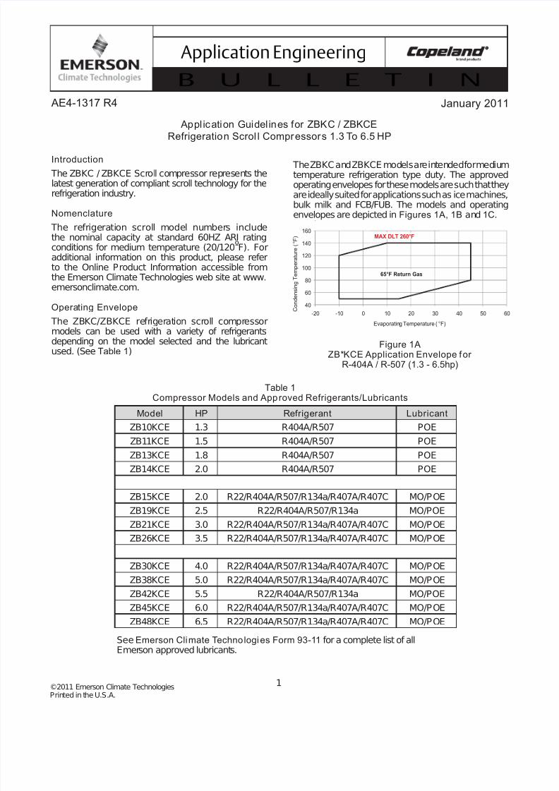
The ZBKC and ZBKCE models are intended for mediumtemperature refrigeration type duty. The approvedoperating envelopes for these models are such that theyare ideally suited for applications such as ice machines,bulk milk and FCB/FUB. The models and operatingenvelopes are depicted in Figures 1A, 1B and 1C.
See Emerson Climate Technologies Form 93-11 for a complete list of allEmerson approved lubricants.
Table 1Compressor Models and Approved Refrigerants/Lubricants
Model HP Refrigerant LubricantZB10KCE 1.3 R404A/R507 POE
ZB11KCE 1.5 R404A/R507 POE
ZB13KCE 1.8 R404A/R507 POE
ZB14KCE 2.0 R404A/R507 POE
ZB15KCE 2.0 R22/R404A/R507/R134a/R407A/R407C MO/POE
ZB19KCE 2.5 R22/R404A/R507/R134a MO/POE
ZB21KCE 3.0 R22/R404A/R507/R134a/R407A/R407C MO/POE
ZB26KCE 3.5 R22/R404A/R507/R134a/R407A/R407C MO/POE
ZB30KCE 4.0 R22/R404A/R507/R134a/R407A/R407C MO/POE
ZB38KCE 5.0 R22/R404A/R507/R134a/R407A/R407C MO/POE
ZB42KCE 5.5 R22/R404A/R507/R134a MO/POE
ZB45KCE 6.0 R22/R404A/R507/R134a/R407A/R407C MO/POE
ZB48KCE 6.5 R22/R404A/R507/R134a/R407A/R407C MO/POE
Figure 1AZB*KCE Application Envelope for
R-404A / R-507 (1.3 - 6.5hp)
-10 50
-10 120
10 140
45 140
45 80
15 50
-10 50
-10 120
10 140
15 140
-10 100
-10 12040
60
80
100
120
140
160
-20 -10 0 10 20 30 40 50 60 C o n d e n s i n g T
e m p e r a t u r e ( ° F )
Evaporating Temperature ( °F)
65°F Return Gas
MAX DLT 260°F
7/28/2019 AE1317
http://slidepdf.com/reader/full/ae1317 2/10
2©2011 Emerson Climate Technologies
Printed in the U.S.A.
AE4-1317 R4
Application Engineering
B U L L E T I N
Accumulators
Due to the scrolls’ inherent ability to handle liquidrefrigerant in flooded start and defrost cycle operationconditions, accumulators may not be required. Anaccumulator is required on single compressor systemswhen the charge limitations exceed those values listed inTable 2. On systems with defrost schemes or transientoperations that allow prolonged uncontrolled liquid returnto the compressor, an accumulator is required unless
a suction header of suf ficient volume to prevent liquidmigration to the compressor is used.
Model Family Chrg. Lmts.
ZB10,11,13,14KCE 6 lbs
ZB15,19, 21, 26, 30, 38, 45, 48KC/E 10 lbs
Table 2 – Charge Limitations
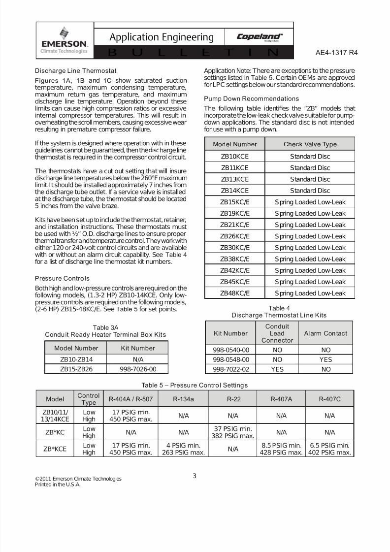
Figure 1CZB*KCE Application Envelope for 134a 2-6.5 HP
Model Part No. Volts Watts Length
ZB10,11, 13, 14 018-0052-00 120 40 21”
ZB10,11, 13, 14 018-0052-01 240 40 21”
ZB15, 19, 21, 26
ZB 30, 38, 45, 48018-0057-00 240 70 21”
ZB15, 19, 21, 26
ZB 30, 38, 45, 48018-0057-01 480 70 21”
ZB15, 19, 21, 26
ZB 30, 38, 45, 48018-0057-02 575 70 21”
ZB15, 19, 21, 26
ZB 30, 38, 45, 48018-0057-03 240 70 32”
ZB15, 19, 21, 26
ZB 30, 38, 45, 48018-0057-04 240 70 48”
ZB15, 19, 21, 26
ZB 30, 38, 45, 48018-0057-05 480 70 48”
ZB15, 19, 21, 26
ZB 30, 38, 45, 48018-0057-06 575 70 48”
ZB15, 19, 21, 26
ZB 30, 38, 45, 48018-0057-07 120 70 48”
Table 3Crankcase Heater
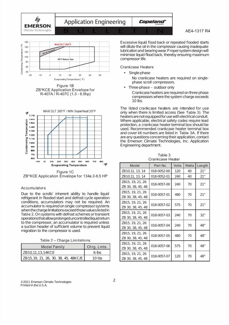
Figure 1BZB*KCE Application Envelope for
R-407A / R-407C (1.3 - 6.5hp)
Excessive liquid flood back or repeated flooded startswill dilute the oil in the compressor causing inadequatelubrication and bearing wear. Proper system design willminimize liquidflood back, thereby ensuring maximumcompressor life.
Crankcase Heaters
• Single-phase
No crankcase heaters are required on single-phase scroll compressors.
• Three-phase – outdoor only
Crankcase heaters are required on three phasecompressors where the system charge exceeds10 lbs.
The listed crankcase heaters are intended for use
only when there is limited access (See Table 3). Theheaters are not equipped for use with electrical conduit.Where applicable, electrical safety codes require leadprotection, a crankcase heater terminal box should beused. Recommended crankcase heater terminal boxand cover kit numbers are listed in Table 3A. If thereare any questions concerning their application, contactthe Emerson Climate Technologies, Inc. ApplicationEngineering department.
40
60
80
100
120
140
160
-20 -10 0 10 20 30 40 50 C o n d e n s i n g T e m p
e r a t u r e ( ° F )
Evaporating Temperature ( °F)
2 0 F S H
R e q u i r
e d
65°F Return Gas
MAX DLT 260°F
7/28/2019 AE1317
http://slidepdf.com/reader/full/ae1317 3/10
3©2011 Emerson Climate Technologies
Printed in the U.S.A.
AE4-1317 R4
Application Engineering
B U L L E T I N
Model Number Check Valve Type
ZB10KCE Standard Disc
ZB11KCE Standard Disc
ZB13KCE Standard Disc
ZB14KCE Standard DiscZB15KC/E Spring Loaded Low-Leak
ZB19KC/E Spring Loaded Low-Leak
ZB21KC/E Spring Loaded Low-Leak
ZB26KC/E Spring Loaded Low-Leak
ZB30KC/E Spring Loaded Low-Leak
ZB38KC/E Spring Loaded Low-Leak
ZB42KC/E Spring Loaded Low-Leak
ZB45KC/E Spring Loaded Low-Leak
ZB48KC/E Spring Loaded Low-Leak
Table 5 – Pressure Control Settings
ModelControl
TypeR-404A / R-507 R-134a R-22 R-407A R-407C
ZB10/11/13/14KCE
LowHigh
17 PSIG min.450 PSIG max.
N/A N/A N/A N/A
ZB*KCLowHigh
N/A N/A37 PSIG min.
382 PSIG max.N/A N/A
ZB*KCELowHigh
17 PSIG min.450 PSIG max.
4 PSIG min.263 PSIG max.
N/A8.5 PSIG min.428 PSIG max.
6.5 PSIG min.402 PSIG max.
Discharge Line Thermostat
Figures 1A, 1B and 1C show saturated suctiontemperature, maximum condensing temperature,
maximum return gas temperature, and maximumdischarge line temperature. Operation beyond theselimits can cause high compression ratios or excessiveinternal compressor temperatures. This will result inoverheating the scroll members, causing excessive wearresulting in premature compressor failure.
If the system is designed where operation with in theseguidelines cannot be guaranteed, then the discharge linethermostat is required in the compressor control circuit.
The thermostats have a cut out setting that will insuredischarge line temperatures below the 260°F maximumlimit. It should be installed approximately 7 inches from
the discharge tube outlet. If a service valve is installedat the discharge tube, the thermostat should be located5 inches from the valve braze.
Kits have been set up to include the thermostat, retainer,and installation instructions. These thermostats mustbe used with ½” O.D. discharge lines to ensure properthermal transfer and temperature control. They work witheither 120 or 240-volt control circuits and are availablewith or without an alarm circuit capability. See Table 4 for a list of discharge line thermostat kit numbers.
Pressure Contro ls
Both high and low-pressure controls are required on thefollowing models, (1.3-2 HP) ZB10-14KCE. Only low-pressure controls are required on the following models,(2-6 HP) ZB15-48KC/E. See Table 5 for set points.
Model Number Kit Number
ZB10-ZB14 N/A
ZB15-ZB26 998-7026-00
Table 3AConduit Ready Heater Terminal Box Kits
Table 4Discharge Thermostat Line Kits
Kit Number Conduit
LeadConnector
Alarm Contact
998-0540-00 NO NO
998-0548-00 NO YES
998-7022-02 YES NO
Application Note: There are exceptions to the pressuresettings listed in Table 5. Certain OEMs are approvedfor LPC settings below our standard recommendations.
Pump Down Recommendations
The following table identifies the “ZB” models thatincorporate the low-leak check valve suitable for pump-down applications. The standard disc is not intendedfor use with a pump down.

7/28/2019 AE1317
http://slidepdf.com/reader/full/ae1317 4/10
4©2011 Emerson Climate Technologies
Printed in the U.S.A.
AE4-1317 R4
Application Engineering
B U L L E T I N
Typically, the compressors that use the low-leakdischarge check valve are suitable for pump downapplications. This valve prevents system pressures fromequalizing and pump down can be achieved. However,during laboratory testing, we have observed a potentialshort cycling condition on the ZB15 through ZB26 models.
This phenomenon can be attributed to several factors:
1. Location of low-pressure control sensor. If it islocated right at the suction inlet of the compressor,it will be more sensitive to pressure spikes.
2. Actual low-pressure setting. Refer to ourrecommended setting inTable 5. If the differentialpressure setting is too close, this will increase thepossibility of short cycling.
3. Type of Low-pressure control can have an effect
on cycling. The encapsulated non-adjustable typeis more susceptible to causing excessive cyclingdue to tolerances.
4. If short cycling cannot be avoided, using a 3-minutetime delay will limit the cycling of the compressorto an acceptable level.
The ZB10 through ZB14 models will require the followingrecommendations for pump down applications:
1. Install an external check-valve in the discharge lineto prevent back-flow from the high side to low side.Install check-valve as close to the compressor
dischargefitting as possible to minimize dischargegas volume.
2. Set low pressure to recommended settings inTable 5.
3. Since these models are single-phase only, add atime delay relay to prevent reverse rotation. Referto “Brief Power Interruptions” section on page 6of this bulletin for additional information.
IPR Valve
Refrigeration scroll compressors (2-6.5 hp) ZB15-48KC/E have internal pressure relief valves, which
open at a discharge to suction differential pressure of 375 to 450 psi. This action will trip the motor protectorand remove the motor from the line. The ZB10-14KCEmodels DO require a high pressure control in additionto a low pressure control, since these models do nothave an IPR valve.
Internal Temperature Protection
Refrigeration Scroll compressors (1.3-6.5 hp) ZB10-48KC/E incorporate a thermo disc which is a temperature-
sensitive snap disc device located at the scroll dischargeport. It is designed to open and route hot dischargegas back to the motor protector thus removing thecompressor from the line.
Motor Protection
Conventional inherent internal line break motorprotection is provided.
Oil Types
Polyol ester lubricants must be provided if the scrollcompressor is to be used with HFC refrigerants. ZBKCcompressors are intended for use with R22 and aresupplied with mineral oil. SeeForm 93-11 for a completelist of all Emerson approved lubricants.
Oil Charges The recommended oil charges for these compressorsare shown in Table 6.
Oil Management for Rack Applications
Copeland Scroll® refrigeration compressors may beused on multiple compressor parallel rack applications.
This requires the use of an oil management systemto maintain proper oil level in each compressorcrankcase. The sight glass connection suppliedcan accommodate the mounting of the oil controldevices.
Unlike semi-hermetic compressors, scroll compressorsdo not have an oil pump with accompanying oil pressuresafety controls. Therefore, an external oil level controlis required.
Table 6Recommended Oil Charges by Model Family
Note: The oil level of refrigeration scroll compressorsshould be adjusted to the mid-point of the sightglassduring normal operation.
Model Family Initial Recharge
ZB10KCE 25 22
ZB11, 13, 14KCE 25 21
ZB15KC/E 44 40
ZB19, 21, 26KC/E 49 45ZB30KC/E 64 60
ZB38KC/E 64 60
ZB45KC/E 64 60
ZB48KCE 60 56

7/28/2019 AE1317
http://slidepdf.com/reader/full/ae1317 5/10
5©2011 Emerson Climate Technologies
Printed in the U.S.A.
AE4-1317 R4
Application Engineering
B U L L E T I N
The Emerson OMB Oil Level Management Controlcombines the functions of level control and timedcompressor shut-off should the level not come back tonormal within a set period of time. This device has beenfound to provide excellent performance infield tests onCopeland Scroll compressors and is recommended forparallel system applications.
Note: Emerson Climate Technologies' ApplicationEngineering Department should be contacted for approved oil management systems.
Immediately after system start-up the oil reservoir levelwillfluctuate until equilibrium is reached. It is advisable tomonitor the oil level during this time to assure suf ficientoil is available. This will prevent unnecessary trips of the oil control system.
Note: If oil management problems are occuringplease refer to AE 17-1320 or contact the EmersonClimate Technologies, Inc. Appl ication EngineeringDepartment.
Note: ZB50, 58, 66, 76, 88 are not approved for rackapplications due to compressor limitations.
Compressor Tubing and Mounting
Compressor mounting must be selected based onapplication. Consideration must be given to soundreduction and tubing reliability. Some tubing geometryor “shock loops” may be required to reduce vibration
transferred from the compressor to external tubing.
Mounting for Rack Systems
For 1.3-6.5 HP compressors, specially designed rubbergrommets are available for refrigeration scroll compressorapplications. These grommets are formulated from adurometer material specifically designed for refrigerationapplications. The durometer limits the compressormotion, thereby minimizing potential problems of excessive tubing stress. Suf ficient isolation is provided toprevent vibration from being transmitted to the mountingstructure. This mounting arrangement is recommendedfor multiple compressor rack installations. See Figure2A for a detail of this mounting system.
Note: The use of standard soft grommets is notrecommended for most refrigeration scroll rackinstallations. These softer mounts allow for excessivemovement that will result in tube breakage, unless theentire system is properly designed.
Condensing Unit Mounting
For 1.3-6.5 H.P. refrigeration scroll condensing unit
applications, soft mounts are recommended. SeeFigure 2B.
Tubing Considerations – Proper tube design must be
taken into consideration when designing the tubingconnecting the scroll to the remaining system. Thetubing should provide enough “flexibility” to allow normalstarting and stopping of the compressor without exertingexcessive stress on the tube joints. In addition, it isdesirable to design tubing with a natural frequency awayfrom the normal running frequency of the compressor.Failure to do this can result in tube resonance andunacceptable tubing life. Figure 3 shows examples of acceptable tubing configurations.
Caution: These examples are intended only asguidelines to depict the need forflexibility in tube designs.In order to properly determine if a design is appropriate
for a given application, samples should be tested andevaluated for stress under various conditions of useincluding voltage, frequency, and load fluctuations,and shipping vibration. The guidelines above maybe helpful; however, testing should be performedfor each system designed.
Starting Characteristics
Single-phase scroll compressors are designed with PSCtype motors and therefore will start without the needof start assist devices in most applications. However,if low voltage conditions exist at start up, protectortrips can result. Therefore, start assist devices (start
capacitors and relays) are available to maximize startingcharacteristics under abnormal conditions.
Fusite
Fusite pin orientation for single-phase and three- phaserefrigeration scroll compressors are shown inFigure 4 and inside the terminal box.
Shell Temperature
System component failure may cause the top shell anddischarge line to briefly reach temperatures above 300°F.Wiring or other materials, which could be damaged bythese temperatures, should not come in contact withthe shell.
Connection Fittings
Scroll compressors are provided with either brazeconnections or roto-lock adapters depending on the billof material selected (reference AE4-1219 for roto-locktorque values).
(Consult your District Sales Manager or ApplicationEngineer for details).

7/28/2019 AE1317
http://slidepdf.com/reader/full/ae1317 6/10
6©2011 Emerson Climate Technologies
Printed in the U.S.A.
AE4-1317 R4
Application Engineering
B U L L E T I N
All ZBKC/E models have copper plated steel suctionand dischargefittings for a more rugged, leak resistantconnection.
See section on New Installation (see Figure 6) forsuggestions on how to properly braze these fittings.
Three-Phase Rotation Direction
Scroll compressors are directional dependent: i.e., theywill compress in one rotational direction only. On single-phase compressors, this is not an issue since they willonly start and run in the proper direction (except asdescribed in the Labeled Brief Power Interruptions).
Three-phase scrolls, however, will rotate in eitherdirection depending on the power of the phasing. Sothere is a 50/50 chance of connected power being“backwards.” Contractors should be warned of this.Appropriate instructions or notices should be providedby the Original Equipment Manufacturer.
Verification of proper rotation can be made by observingthat the suction pressure drops and the dischargepressure rises when the compressor is energized.Additionally, if operated in reverse the compressor isnoisier and its current draw is substantially reducedcompared to tabulated values.
Although operation of scroll in reverse direction for brief periods of time is not harmful, continued operation couldresult in failure.
All three-phase compressors are wired identically
internally. Once the correct phasing is determined fora specific system or installation, connecting properlyphased power leads to the same fusite terminals willmaintain the proper rotation.
Brief Power Interruptions
Brief power interruptions (less than ½ second) mayresult in powered reverse rotation of single-phaserefrigeration scroll compressors. High-pressuredischarge gas expands backward through the scrollsat power interruption causing the scroll to orbit inthe reverse direction. If power is reapplied while thisreversal is occurring, the compressor may continue torun noisily in the reverse direction for several minutes
until the compressor internal protector trips. This has nonegative effect on durability. When the protector resets,the compressor will start and run normally.
Emerson strongly encourages the use of a timerwhich can sense brief power interruptions and lock the
compressor out of operation for two minutes. A typicaltimer circuit is shown in Figure 5.
No time delay is required on three phase models to
prevent reverse rotation due to power interruptions.
Deep Vacuum Operation
WARNING: DO NOT RUN A REFRIGERATIONSCROLL COMPRESSOR IN A VACUUM. FAILURE TOHEED THIS ADVICE CAN RESULT IN PERMANENTDAMAGE TO THE COMPRESSOR.
A low-pressure control is required for protection againstvacuum operation. See the section on pressure controlsfor the proper set points. (See Table 5)
Scroll compressors (as with any refrigeration compressor)should never be used to evacuate refrigeration or air
conditioning systems. See AE24-1105 for proper systemevacuation procedures.
Unbrazing System Components
CAUTION!
If the refrigerant charge is removed from a scroll unitby bleeding the high side only, it is sometimes possiblefor the scrolls to seal, preventing pressure equalizationthrough the compressor. This may leave the low side shelland suction line tubing pressurized. If a brazing torch isthen applied to the low side, the pressurized refrigerantoil mixture could ignite as it escapes and contacts thebrazingflame. It is important to check both the high and
low sides with manifold gauges before unbrazing. In thecase of an assembly line repair, remove the refrigerantfrom both the high and low sides. Instructions shouldbe provided in appropriate product literatures andassembly areas.
Hi-Pot Testing
Refrigeration scroll compressors are configured withthe motor in the bottom of the shell. Unlike most otherhermetic compressors, the motor of a scroll compressorcan be immersed in refrigerant when liquid is presentin the shell. Hi-Pot tests with liquid refrigerant in theshell can show higher levels of current leakage due tothe higher electrical conductivity of liquid refrigerant vs.
refrigerant vapor and oil. This phenomenon can occurwith any compressor when the motor is immersed inrefrigerant and does not present any safety issue. Tolower the current leakage reading, operate the systemfor a brief period of time redistributing the refrigerant toa more normal configuration and test again.

7/28/2019 AE1317
http://slidepdf.com/reader/full/ae1317 7/10
7©2011 Emerson Climate Technologies
Printed in the U.S.A.
AE4-1317 R4
Application Engineering
B U L L E T I N
Copeland Scroll® Functional Check
Refrigeration scroll compressors do not have internalsuction valves. It is not necessary to perform functional
compressor tests to check how low the compressor willpull suction pressure. This type of test may damage ascroll compressor. The following diagnostic procedureshould be used to evaluate whether a Copeland Scrollcompressor is functioning properly.
1. Verify proper unit voltage.
2. Normal motor winding continuity and short toground checks will determine if the inherentoverload motor protector has opened or if aninternal short to ground has developed. If theprotector has opened, the compressor must coolsuf ficiently to reset.
3. With service gauges connected to suctionand discharge pressure fittings, turn on thecompressor. If suction pressure falls below normallevels, the system is either low on charge or thereis a flow blockage.
4a. Single-Phase Compressors
If the suction pressure does not drop and thedischarge pressure does not rise to normal levelsthe compressor is faulty.
4b. Three-Phase Compressors
If the suction pressure does not drop and thedischarge pressure does not rise, reverse anytwo of the compressor power leads and reapplypower to make sure the compressor was not wiredto run in the reverse direction.
The compressor current draw must be compared topublished compressor performance curves at thecompressor operating conditions (pressures andvoltages). Significant deviations (±15%) from publishedvalues may indicate a faulty compressor.
New Installation
• The copper-coated steel suction, discharge, and
injection tubes on scroll compressors can bebrazed in approximately the same manner asany copper tube.
• Recommended brazing material – Any Silfosmaterial is recommended, preferably with aminimum of 5% silver. However, 0% silver isacceptable.
• Use of a dry nitrogen purge to eliminate possibilityof carbon buildup on internal tube surfaces isrecommended.
• Be sure process tube fitting I.D. and processtube O.D. are clean prior to assembly.
• Apply heat in Area 1. As tube approaches brazingtemperature, move torchflame to Area 2. (SeeFigure 6)
• Heat Area 2 until braze temperature is attained,moving torch up and down and rotating aroundtube as necessary to heat tube evenly. Add brazematerial to the joint while moving torch aroundcircumference.
• After braze materialflows around joint, move torch
to heat Area 3. This will draw the braze materialdown into the joint. The time spent heating Area3 should be minimal.
• As with any brazed joint, overheating may bedetrimental to the final result.
Field Service
To disconnect:
• Recover refrigerant from both the high and lowside of the system. Cut tubing near compressor.
To reconnect:
• Recommended brazing materials – Silfos withminimum 5% silver or silver braze material withflux.
• Reinsert tubingfitting.
• Heat tube uniformly in Area 1, moving slowly toArea 2. When joint reaches brazing temperature,apply brazing material. (See Figure 6)
• Heat joint uniformly around the circumference toflow braze material completely around the joint.
• Slowly move torch in Area 3 to draw braze materialinto the joint.
Do not overheat joint.
Figure 6Scroll Tube Brazing

7/28/2019 AE1317
http://slidepdf.com/reader/full/ae1317 8/10
8©2011 Emerson Climate Technologies
Printed in the U.S.A.
AE4-1317 R4
Application Engineering
B U L L E T I N
Figure 2A1.3-6.5 HP Refrigeration Scroll Rack Mounting
Figure 2B1.3-6.5 HP Refrigeration Scroll Condensing Unit Mounting
Kit 527-0157-00

7/28/2019 AE1317
http://slidepdf.com/reader/full/ae1317 9/10
9©2011 Emerson Climate Technologies
Printed in the U.S.A.
AE4-1317 R4
Application Engineering
B U L L E T I N
NOTES:
1. The above tubing configurations are guidelines to minimize tube stress.2. Follow similar guidelines for discharge tubing and oil return tubing as needed.3. If a run of over 20” is required, intermediate clamps may be necessary.4. Do not hang weights on tubing (e.g. filter drier on suction tubing) except after clamps or close
to the header.5. Tube runs of less than 8” are not recommended.6. This dimension should be made as short as possible (e.g. 2” or less) but still insuring a proper
braze joint.7. The above tubing recommendations are based on “no elbow joints”. The use of continuous
tubing is preferred.
Figure 4Motor Terminal (Fusite) Connections for
Single Phase and Three Phase Scrolls
Figure 3Typical Suction Tubing

7/28/2019 AE1317
http://slidepdf.com/reader/full/ae1317 10/10
10©2011 Emerson Climate Technologies
Printed in the U.S.A.
AE4-1317 R4
Application Engineering
B U L L E T I N
Figure 5Scroll Wiring Schematic
(Optional)
Compressor
Contactor
Coil


