Embed Size (px)
Citation preview
AHP – Hydraulikzylinder
mit integriertem Wegmesssystem
AHP – Hydraulic cylinder with integrated linear position transducer
AHP – Vérin hydraulique avec système de mesure intégré
HMZ 250

DrehantriebRotating Drive UnitEntraînement rotatif
StandardzylinderAHP Standard cylinder
Vérin standard
SchiebereinheitPush unit
Unités de translation
Wir bringen Qualität in UmlaufWe set quality in motionNous faisons avancer la qualité
BlockzylinderBlock Cylinder
Vérin bloc
NormzylinderDIN Standard cylinder
Vérin normalisé
KernzugeinheitCore Pull Unit
Unité tire-noyau

Grundlagen 4Basic principles
Principes de base
Informationen und Hinweise 6Information and instructions
Informations et remarques
Hydraulikzylinder mit integriertem Wegmesssystem (HMZ 250)Hydraulic cylinder with integrated linear position transducer (HMZ 250)
Vérin hydraulique avec système de mesure intégré (HMZ 250)
HMZ 250 - 00 / 01/ 001 8
HMZ 250 - 02 / 03 / 04 10
HMZ 250 -10 /11 12
Zubehör 14Accessories
Accessoires
InhaltContents
Sommaire
01-04 / 2007 3
SeitePage
Page
4
GrundlagenBasic principles
Principes de base
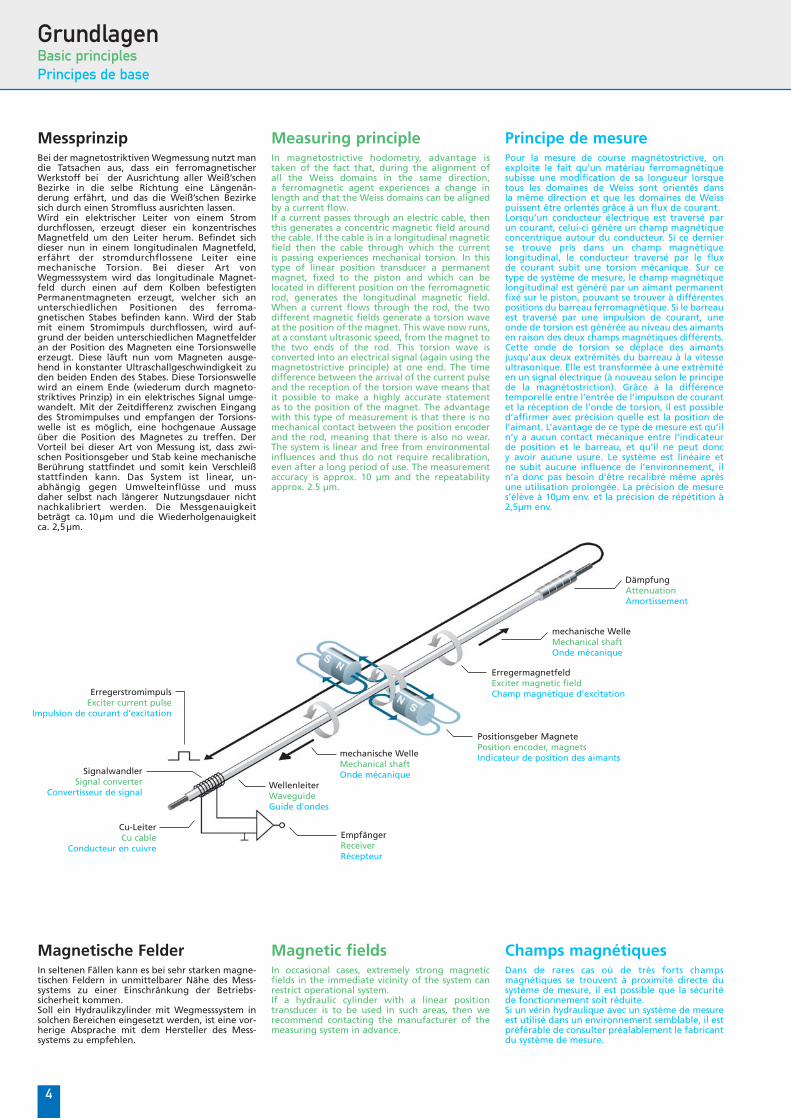
MessprinzipBei der magnetostriktiven Wegmessung nutzt mandie Tatsachen aus, dass ein ferromagnetischerWerkstoff bei der Ausrichtung aller Weiß’schenBezirke in die selbe Richtung eine Längenän-derung erfährt, und das die Weiß’schen Bezirkesich durch einen Stromfluss ausrichten lassen.Wird ein elektrischer Leiter von einem Stromdurchflossen, erzeugt dieser ein konzentrischesMagnetfeld um den Leiter herum. Befindet sichdieser nun in einem longitudinalen Magnetfeld,erfährt der stromdurchflossene Leiter einemechanische Torsion. Bei dieser Art vonWegmesssystem wird das longitudinale Magnet-feld durch einen auf dem Kolben befestigtenPermanentmagneten erzeugt, welcher sich anunterschiedlichen Positionen des ferroma-gnetischen Stabes befinden kann. Wird der Stabmit einem Stromimpuls durchflossen, wird auf-grund der beiden unterschiedlichen Magnetfelderan der Position des Magneten eine Torsionswelleerzeugt. Diese läuft nun vom Magneten ausge-hend in konstanter Ultraschallgeschwindigkeit zuden beiden Enden des Stabes. Diese Torsionswellewird an einem Ende (wiederum durch magneto-striktives Prinzip) in ein elektrisches Signal umge-wandelt. Mit der Zeitdifferenz zwischen Eingangdes Stromimpulses und empfangen der Torsions-welle ist es möglich, eine hochgenaue Aussageüber die Position des Magnetes zu treffen. DerVorteil bei dieser Art von Messung ist, dass zwi-schen Positionsgeber und Stab keine mechanischeBerührung stattfindet und somit kein Verschleißstattfinden kann. Das System ist linear, un-abhängig gegen Umwelteinflüsse und mussdaher selbst nach längerer Nutzungsdauer nichtnachkalibriert werden. Die Messgenauigkeitbeträgt ca. 10µm und die Wiederholgenauigkeitca. 2,5µm.
Measuring principleIn magnetostrictive hodometry, advantage istaken of the fact that, during the alignment ofall the Weiss domains in the same direction,a ferromagnetic agent experiences a change inlength and that the Weiss domains can be alignedby a current flow.If a current passes through an electric cable, thenthis generates a concentric magnetic field aroundthe cable. If the cable is in a longitudinal magneticfield then the cable through which the currentis passing experiences mechanical torsion. In thistype of linear position transducer a permanentmagnet, fixed to the piston and which can belocated in different position on the ferromagneticrod, generates the longitudinal magnetic field.When a current flows through the rod, the twodifferent magnetic fields generate a torsion waveat the position of the magnet. This wave now runs,at a constant ultrasonic speed, from the magnet tothe two ends of the rod. This torsion wave isconverted into an electrical signal (again using themagnetostrictive principle) at one end. The timedifference between the arrival of the current pulseand the reception of the torsion wave means thatit possible to make a highly accurate statementas to the position of the magnet. The advantagewith this type of measurement is that there is nomechanical contact between the position encoderand the rod, meaning that there is also no wear.The system is linear and free from environmentalinfluences and thus do not require recalibration,even after a long period of use. The measurementaccuracy is approx. 10 µm and the repeatabilityapprox. 2.5 µm.
Principe de mesurePour la mesure de course magnétostrictive, onexploite le fait qu’un matériau ferromagnétiquesubisse une modification de sa longueur lorsquetous les domaines de Weiss sont orientés dansla même direction et que les domaines de Weisspuissent être orientés grâce à un flux de courant.Lorsqu’un conducteur électrique est traversé parun courant, celui-ci génère un champ magnétiqueconcentrique autour du conducteur. Si ce dernierse trouve pris dans un champ magnétiquelongitudinal, le conducteur traversé par le fluxde courant subit une torsion mécanique. Sur cetype de système de mesure, le champ magnétiquelongitudinal est généré par un aimant permanentfixé sur le piston, pouvant se trouver à différentespositions du barreau ferromagnétique. Si le barreauest traversé par une impulsion de courant, uneonde de torsion est générée au niveau des aimantsen raison des deux champs magnétiques différents.Cette onde de torsion se déplace des aimantsjusqu’aux deux extrémités du barreau à la vitesseultrasonique. Elle est transformée à une extrémitéen un signal électrique (à nouveau selon le principede la magnétostriction). Grâce à la différencetemporelle entre l’entrée de l’impulson de courantet la réception de l’onde de torsion, il est possibled’affirmer avec précision quelle est la position del’aimant. L’avantage de ce type de mesure est qu’iln’y a aucun contact mécanique entre l’indicateurde position et le barreau, et qu’il ne peut doncy avoir aucune usure. Le système est linéaire etne subit aucune influence de l’environnement, iln’a donc pas besoin d’être recalibré même aprèsune utilisation prolongée. La précision de mesures’élève à 10µm env. et la précision de répétition à2,5µm env.
ErregerstromimpulsExciter current pulse
Impulsion de courant d’excitation
Cu-LeiterCu cable
Conducteur en cuivre
EmpfängerReceiverRécepteur
WellenleiterWaveguideGuide d’ondes
mechanische WelleMechanical shaftOnde mécanique
Positionsgeber MagnetePosition encoder, magnetsIndicateur de position des aimants
ErregermagnetfeldExciter magnetic fieldChamp magnétique d’excitation
Signalwandler Signal converter
Convertisseur de signal
mechanische WelleMechanical shaftOnde mécanique
DämpfungAttenuationAmortissement
Magnetische Felder In seltenen Fällen kann es bei sehr starken magne-tischen Feldern in unmittelbarer Nähe des Mess-systems zu einer Einschränkung der Betriebs-sicherheit kommen.Soll ein Hydraulikzylinder mit Wegmesssystem insolchen Bereichen eingesetzt werden, ist eine vor-herige Absprache mit dem Hersteller des Mess-systems zu empfehlen.
Magnetic fields In occasional cases, extremely strong magneticfields in the immediate vicinity of the system canrestrict operational system.If a hydraulic cylinder with a linear positiontransducer is to be used in such areas, then werecommend contacting the manufacturer of themeasuring system in advance.
Champs magnétiques Dans de rares cas où de très forts champsmagnétiques se trouvent à proximité directe dusystème de mesure, il est possible que la sécuritéde fonctionnement soit réduite.Si un vérin hydraulique avec un système de mesureest utilisé dans un environnement semblable, il estpréférable de consulter préalablement le fabricantdu système de mesure.

5
SchnittstellenUm das Wegmesssystem an eine Maschinen-steuerung anzubinden, wird eine Schnittstellebenötigt. Magnetostriktive Wegmesssystemebieten eine Vielzahl an Schnittstellen. Um dieAuswahl zu erleichtern soll im Folgenden einkleiner Überblick gegeben werden:
Analoge AusgängeBei analogen Ausgängen werden je nach Positiondes Kolbens unterschiedliche Spannungs- bzw.Stromsignale ausgegeben. Hierbei stehenAusgangssignale von 0 bis 10V, -10 bis +10V, 20mAbis 0mA usw. zur Verfügung. Eine Auswertung derDaten ist bei dieser Lösung relativ einfach möglich.Möchte man jedoch eine möglichst genaue unddirekte Aussage über die Position des Kolbenshaben, ist diese Art der Messwegerfassung nichtdie ideale Variante. In den meisten Anwendungs-fällen reicht die erzielbare Genauigkeit jedochaus.
Digitale Impulsschnittstellen (Start–Stop)Bei dieser Schnittstelle wird von Messsystem einStart- und ein Stop-Signal gesendet. Die Zeit-differenz der beiden Signale ist direkt proportio-nal zur Position des zu messenden Objekts. Einenachgeschaltete Auswerteeinheit kann dadurchdie Position und auch die Geschwindigkeit ermit-teln. Der Vorteil der Impulsübertragung ist diehohe Störungsunempfindlichkeit gegen Umwelt-einflüsse und die hohe Übertragungsentfernung(bis 500m).
Synchron Serielle Datenübertragung (SSI)Bei dieser Schnittstelle wird die Information derKolbenposition als Datenantwort übergeben, unddie gesendeten Informationen können von denmeisten Steuerungen direkt weiterverarbeitetwerden.Der Verkabelungsaufwand ist vergleichsweisegering, und dabei sehr zuverlässig und robust inindustriellen Anwendungen. Diese Schnittstelle istdie am meisten verbreitete.Bei der Impuls- wie auch der SSI-Schnittstelle wirddie Position des Wegaufnehmers synchron zurAchsregelkarte übertragen, wodurch eine hochge-naue Regelung erzielt werden kann.
CAN-BusDer CAN-Bus ist ein asynchrones, serielles Bus-system. Daten können von jedem Teilnehmergesendet und empfangen werden, wobei beijedem Teilnehmer am Bus eine Priorität zugeord-net werden kann. Damit wird sichergestellt, dasssicherheitsrelevante Daten auf dem schnellst-möglichen Weg am Empfänger ankommen. DieDatenübertragung erfolgt meist über eine kosten-günstige 2-Draht Leitung. Im KFZ-Bereich wird derCAN-Bus seit Jahren erfolgreich eingesetzt.
ProfibusDer Profibus ist ein universeller serieller Feldbus.Im Gegensatz zum CAN-Bus sind die Teilnehmer imBus in Master und Slave aufgeteilt. WährendMaster unaufgefordert Daten versenden können,dürfen Slaves nur auf Aufforderung eines anderenTeilnehmers Daten versenden. Es können Übertra-gungsraten von bis zu 12 Mbit/s erreicht werden,und dies bei einer Anbindung an alle gängigenMaschinensteuerungen.
WeitereDie oben genannten Anbindungen sind diemeist verbreiteten. Weitere Systeme wie InterBus,MODBUS oder DeviceNet stehen auf Anfrage zurVerfügung.
InterfacesAn interface is required to connect the linearposition transducer to a machine controller.Magnetostrictive linear position transducers canoffer a variety of interfaces. To simplify theselection, the following selection offers a briefoverview:
Analog outputsIn the case of analog outputs, different voltage orcurrent signals are output, depending on theposition of the piston. For this, output signals of0 to 10 V, -10 to +10 V, 20 mA to 0 mA, etc. areavailable. Data evaluation is relatively simple withthis solution. However, if you wish to obtain themost accurate and direct statement possible onthe position of the piston, then this type of linearposition recording is not the ideal variant.Nevertheless, for most applications, the achieveableaccuracy is sufficient.
Digital pulse interfaces (Start–Stop)With this interface, the measuring system sends astart and a stop signal. The difference in timebetween the two signals is directly proportionalto the position of the object to be measured. Adownstream evaluation unit can thus determinethe position and the speed. The advantage of pulsetransmission is the high resistance to environmentalinfluences and the large transmission distance (upto 500 m).
Synchronous serial data transmission (SSI)This interface transfers the information on thepiston position as a data answer and the sentinformation can be processed further by mostcontrollers. The amount of cable required is relatively lowand the interface is very reliable and robust inindustrial applications. This type of interface is themost commonly used.Both the pulse and the SSI interface transmit theposition of the position recorder synchronouslyto the axis control card, allowing high accuracycontrol.
CAN busThe CAN bus is an asynchronous, serial bus system.Each station can send and receive data, and it ispossible to assign a priority to each bus station.This ensures that safety relevant data arrive withthe receiver using the fastest route possible.Data transmission usually takes place along a lowcost, 2 wire cable. The CAN bus has been usedsuccessfully for many years in the car industry.
ProfibusProfibus is a universal, serial field bus. In contrastto the CAN bus, the bus stations are split intoMaster and Slave. Whilst the Master can send datawithout a request, Slaves can only send data at therequest of another station. Transmission rates ofup to 12 Mbit/s are possible, and the system can beconnected to all current machine controllers.
OtherThe above interfaces are the most commontypes. Other systems such as InterBus, MODBUS orDeviceNet are available on request.
InterfacesUne interface est nécessaire pour raccorder lesystème de mesure à une commande de machine.Les systèmes de mesure magnétostrictifs disposentd’une multitude d’interfaces. Afin d’en faciliter lechoix, un petit aperçu est donné ci-dessous :
Sorties analogiquesSelon la position du piston, différents signauxde tension et de courant sont émis sur les sortiesanalogiques. Des signaux de sortie de 0 à 10V,de -10 à +10V, de 20mA à 0mA sont alors entreautres disponibles. Cette solution permet de menerune interprétation des données relativementfacilement. Toutefois, si l’on souhaite obtenirla détermination de la position du piston laplus précise et la plus directe possible, ce typed’acquisition de mesure n’est pas la solutionidéale. La précision atteinte est néanmoinssuffisante dans la plupart des cas d’application.
Interfaces à impulsions numériques(Start–Stop)Dans le cas de cette interface, un signal « Start »et un signal « Stop » sont envoyés depuis le systèmede mesure. Le temps écoulé entre les deuxsignaux est directement proportionnel à la positionde l’objet à mesurer. Une unité d’interprétationmontée en aval peut à partir de cette donnéedéterminer la position ainsi que la vitesse.L’avantage de la transmission par impulsionsest son insensibilité aux perturbations liées àl’environnement et la distance de transmissionélevée (jusqu’à 500 m).
Transmission de données sérielle etsynchrone (SSI)Avec cette interface, l’information concernant laposition du piston est transmise sous la forme deréponse de données, et les informations envoyéespeuvent être traitées directement par la plupartdes commandes.Le câblage nécessaire est également limité ; ilest donc très fiable et robuste dans le cadred’applications industrielles. Cette interface est laplus largement utilisée.Dans le cas des interfaces à impulsions et desinterfaces SSI, la position du capteur de courseest transmise de façon synchrone à la cartede contrôle d’axes, ce qui permet d’obtenir uncontrôle extrêmement précis.
Bus CANLe bus CAN est un système de bus asynchronesériel. Les données peuvent être envoyées et reçuespar chaque abonné et une priorité peut êtreattribuée à chaque abonné du bus. Cela permet des’assurer que les données relatives à la sécuritéparviennent au destinataire par le chemin leplus rapide. La transmission de données s’effectuegénéralement via un simple câble à 2 fils. Le busCAN est utilisé avec succès depuis des années dansle secteur de la technique automobile.
ProfibusLe Profibus est un bus de terrain sériel universel.Contrairement au bus CAN, les abonnés du bussont répartis entre maîtres et esclaves. Alors queles maîtres peuvent envoyer des données à toutmoment, les esclaves ne peuvent en envoyer quesur la demande d’un autre abonné. Il est possibled’atteindre des taux de transmission de 12 Mbits/smax., et ce lorsque le dispositif est raccordé àtoutes les commandes de machine courantes.
AutresLes raccordements cités plus haut sont ceuxles plus fréquemment utilisés. D’autres systèmes,tels qu’Interbus, MODBUS ou DeviceNet sontégalement disponibles sur demande.
AnwendungsgebieteDas magnetostriktive Messprinzip in Kombinationmit Hydraulikzylindern hat sich bisher in einerVielzahl von Anwendungen bewährt. EinigeAnwendungsgebiete sind z.B.:■ Pinolenverstellung von CNC-Drehmaschinen■ Pressen in verschiedenen Ausführungen■ Transporthub bei Spritzgussmaschinen■ Prüfmaschinen■ HubtischeUvm.
Areas of applicationThe magnetostrictive measurement principle,together with hydraulic cylinders has proved itsworth in a variety of applications. Some areas ofapplication are:■ Sleeve adjustment on CNC lathes■ All kinds of presses■ Transport stroke for injection molding machines■ Testing machines■ Elevating platformsand many more
Domaines d’applicationLe principe de mesure magnétostrictif combinéà des vérins hydrauliques a fait la preuve deson efficacité dans le cadre d'une multituded’applications. Parmi ses domaines d’application,on trouve entre autres :■ le déplacement de contre-pointes de tours CNC■ le pressage de toutes sortes de modèles■ la course de transport sur des presses à injection■ les machines d'essai■ les tables élévatricesetc.

800
6
Informationen und HinweiseInformation and instructions
Informations et remarques
BefestigungsartMounting modeMode de fixation
BeschreibungDescriptionDescription
SeitePagePage
StandardausführungStandard versionExécution standard
801
Gewindebefestigung,Außengewinde vorne am Kopf Thread fastener,thread fixing in front at headFixation du filetage,filetage avant sur la tête
9001
Gewindebefestigung,Gewindebohrungen vorne am Kopf Thread fastenerthread holes in front in headFixation du filetage,alésages avant sur la tête
1002 Flanschbefestigung vorneFlange mounting, frontFixation de flasque avant
206regelbarcontrollableréglable
208regelbarcontrollableréglable
Zylinder für Balluff WegmesssystemCylinder for Balluff linear position transducerVérin pour système de mesure Balluff
Zylinder für MTS WegmesssystemCylinder for MTS linear position transducerVérin pour système de mesure MTS
Zylinder für TR WegmesssystemCylinder for TR linear position transducerVérin pour système de mesure TR
EntlüftungVenting Purge
E
DichtungsvarianteSeal variant Varianted’étanchéité
V
Sonderausführung Special model Exécution spéciale
WegmesssystemLinear position transducerSystème de mesure
SonderausführungenSpecial versionsModèles spéciaux
FunktionsartenOperation modes · Modes de fonctionnement
BefestigungsartenMounting modes · Modes de fixation
A B
A B
204regelbarcontrollableréglable
201
FunktionsartOperations modeMode defonctionnement
FunktionsartOperations modeMode defonctionnement
A B
A B
MT0
TR0
Grundsätzlich werden die Zylinder nur für Wegmesssysteme vorbereitetgeliefert. Wegmesssystem und Zubehör können separat bei AHP Merklebestellt werden.The cylinders are always delivered prepared only for linear positiontransducers. The linear position transducer and accessories can be orderedseparately from AHP Merkle.Les vérins sont en principe livrés préparés uniquement pour des systèmesde mesure. Le système de mesure et les accessoires peuvent être commandésséparément auprès de AHP Merkle.
BA0
1103
BefestigungsartMounting modeMode de fixation
BeschreibungDescriptionDescription
SeitePagePage
Haltefuß (Winkel), vorneFastening foot (bracket), frontPied de retenue (équerre), avant
1104
2 Haltefüsse (Winkel), 1x vorne, derzweite auf dem Zylinderrohr verschiebbar2 fastening feet (bracket), 1x front,the second on cylinder tube, slideable2 pieds de retenue (équerre), 1à l'avant,le 2e ajustable sur le tube cylindrique
1210Schwenkzapfen (vorne)Swivel pin (at front)Pivot (avant)
1311Schwenkzapfen (mittig)Swivel pin (at center)Pivot (médian)
BeschreibungDescriptionDescription
doppeltwirkend,Endlagendämpfung vornedouble-acting,end position cushioning at frontà double effet,amortissement en fin de course à l'avant
doppeltwirkend,Endlagendämpfung hintendouble-acting,end position cushioning at rearà double effet, amortissement en fin decourse à l'arrière
BeschreibungDescriptionDescription
doppeltwirkenddouble-actingà double effet
doppeltwirkend,Endlagendämpfung beidseitigdouble-acting,end position cushioning on both sidesà double effet, amortissement en fin decourse des deux côtés
BeidseitigOn both sidesDeux côtés
Werkstoff: Viton (HFD-Flüssigkeiten)oder Temperaturbereich bis 180°CMaterial: Viton (HFD-fluids)or temperatures up to 180° CMatérial: Viton (fluids HFD)ou témperatures jusqu'à 180°C
weitere Sonderausführungen siehe Katalog„Standardzylinder“ oder auf AnfrageAdditional special versions in the „Standardcylinder“ catalog or on requestPour les autres modèles spéciaux, voir lechapitre « Vérins standard » du catalogueou nous contacter

7
EinsetzbareWegmesssystemeFolgende Wegmesssysteme sindmit den im Katalog abgebildetenHydraulikzylindern kompatibel:
Applicable linearposition transducersThe following linear positiontransducers are compatible with thehydraulic cylinders shown in thecatalog:
Systèmes demesure utilisablesLes systèmes de mesure suivantssont compatibles avec les vérinshydrauliques présentés dans lecatalogue :
Bestellbezeichnung (Beispiel)Order Specification (example) · Réference de commande (exemple)
AbmessungenDimensions · Dimensions
HMZ 250 5 0. / 3 2
Ko
lben
ØPi
sto
n Ø
Ø P
isto
n
Hu
bSt
roke
Co
urs
e
Befe
stig
un
gsa
rtM
ou
nti
ng
mo
de
Mo
de
de
fixa
tio
n
Son
der
ausf
üh
run
gen
Spec
ial v
ersi
on
sM
od
èles
sp
écia
ux
TypTypeType
HMZ 250 50 32 max.1000 mm
Sta
ng
en
Ø (
d1)
Ro
d Ø
(d
1)Ø
Tig
e (d
1)
FunktionsartOperation modeMode de fonctionnement
WegmesssystemLinear position transducerSystème de mesure
Balluff
BTL5-…..B…
MTS
RH-M/V…GH-M/V…LH-M…
TR
LA-41…LA-46…
GehäuselängeHousing length · Longueur du boîtier
Balluff
A 74 57 74 82,5 102,5
–* –*
–* –*
Überstand gerader SteckerOverhang, straight connector · Saillie de la fiche droite
B
69 69 69 69 ±3 102,5 ±3
Überstand WinkelsteckerOverhang, angle connector · Saillie de la fiche angulaire
48 48 48
AnalogAnalogAnalogique
Impuls (Start/Stop)Impulse (Start/Stop)Impulsion (Start/Stop)
SSD/SSISSD/SSISSD/SSI
CAN-BusCAN-BusCAN-Bus
ProfibusProfibusProfibus
KabelüberstandCable overhang · Saillie du câble
29 29 29
GehäuselängeHousing length · Longueur du boîtier
MTS
A 68 68 68 68 68
43 40
60 –*
Überstand gerader SteckerOverhang, straight connector · Saillie de la fiche droite
B
65 65 65 65 62
Überstand WinkelsteckerOverhang, angle connector · Saillie de la fiche angulaire
43 43 43
KabelüberstandCable overhang · Saillie du câble
60 60 60
GehäuselängeHousing length · Longueur du boîtier
TR
A6894
–*
948666
11594
115–*LA-41
LA-46
LA-41LA-46
LA-41LA-46
LA-41LA-46
~64~58
–*
~69,5~68,5~69,5
–*~60,5
–*–*
~42~42
–*
~55~54~55
–*~38,5
–*–*
~23,5~21,5
–*
~27~23,5~21,5
~29–*
~29–*
Überstand gerader SteckerOverhang, straight connector · Saillie de la fiche droite
BÜberstand WinkelsteckerOverhang, angle connector · Saillie de la fiche angulaire
KabelüberstandCable overhang · Saillie du câble
Für die Richtigkeit der angegebenen Maße wird keine Haftung übernommen. Änderungen obligen den Herstellern der Wegmesssysteme. (Stand 02/2007)No liability is accepted for the correctness of the given dimensions. The manufacturer of the linear position transducers reserves the right to make changes.(Date 02/2007)Nous déclinons toute responsabilité concernant l'exactitude des dimensions fournies. Les modifications incombent au fabricant du système de mesure.(version 02/2007)
* nicht verfügbar* N/A* non disponible
Balluff GmbH
Schurwaldstraße 973765 Neuhausen a.d.FGermany
Tel.: +49 (0) 7158 / 173 - 0Fax: +49 (0) 7158 / 5010E-Mail: [email protected]
MTS Sensor Technologie GmbH & Co. KG
Auf dem Schüffel 958513 LüdenscheidGermany
Tel.: +49 (0) 2351 / 9587 - 0Fax: +49 (0) 2351 / 56491E-Mail: [email protected]
TR-Electronic GmbH
Eglishalde 6D-78647 TrossingenGermany
Tel.: +49 (0) 7425 / 228 - 0Fax: +49 (0) 7425 / 228-E-Mail: [email protected]
Balluff: -40°C – +85°C
MTS: -40°C – +75°C
TR:0°C – +70°C
8
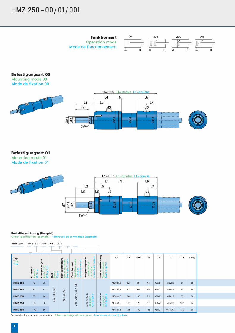
HMZ 250 – 00/ 01 / 001
Befestigungsart 00Mounting mode 00Mode de fixation 00
FunktionsartOperation mode
Mode de fonctionnement
204 206 208201
A B A B A B A B
Befestigungsart 01Mounting mode 01Mode de fixation 01
Bestellbezeichnung (Beispiel)Order specification (example) · Référence de commande (exemple)
HMZ 250 50. / 32 . 100 . 01 . 201
Technische Änderungen vorbehalten. Subject to change without notice Sous réserve de modifications
Ko
lben
ØPi
sto
n Ø
Ø P
isto
n
Hu
bSt
roke
Co
urs
e
Befe
stig
un
gsa
rtM
ou
nti
ng
mo
de
Mo
de
de
fixa
tio
n
So
nd
era
usf
üh
run
gSp
ecia
l ver
sio
nM
od
èle
spéc
ial
TypTypeType
d2
sieh
e Se
ite
6se
e p
age
6vo
ir p
ages
6
Sta
ng
en
Ø (
d1)
Ro
d Ø
(d
1)Ø
Tig
e (d
1)
max
. 100
0m
m
00 /
01/ 0
01
201
/ 204
/ 20
6 / 2
08
25
32
40
50
60
M20x1,5
M24x1,5
M30x1,5
M36x1,5
M45x1,5
d3
62
72
90
115
138
d3V
65
80
100
125
150
d4
48
60
75
92
115
d5
G3/8"
G1/2"
G1/2"
G1/2"
G1/2"
d7
M52x2
M60x2
M76x2
M92x2
M110x3
40HMZ 250
50HMZ 250
63HMZ 250
80HMZ 250
100HMZ 250
Fun
kti
on
sart
Op
erat
ion
mo
de
Mo
de
de
fon
ctio
nn
emen
t
Weg
mess
syst
em
Lin
ear
po
siti
on
tran
sdu
cer
Syst
ème
de
mes
ure
sieh
e Se
ite
6se
e p
age
6vo
ir p
ages
6
d12 d13f7
38
50
60
74
98
54
67
80
102
130
9
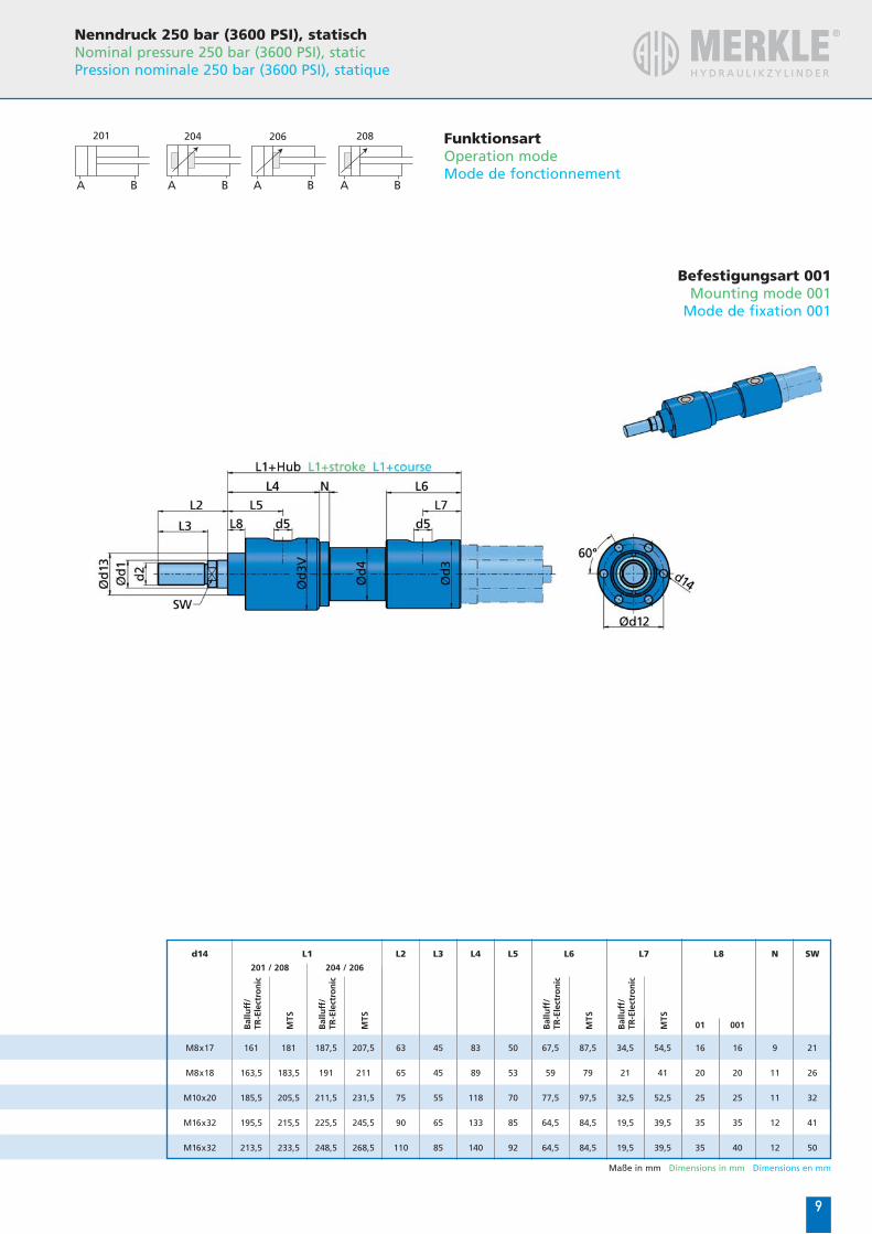
Befestigungsart 001Mounting mode 001
Mode de fixation 001
FunktionsartOperation modeMode de fonctionnement
204 206 208201
A B A B A B A B
Nenndruck 250 bar (3600 PSI), statischNominal pressure 250 bar (3600 PSI), staticPression nominale 250 bar (3600 PSI), statique
Maße in mm Dimensions in mm Dimensions en mm
L1
161
163,5
185,5
195,5
213,5
181
183,5
205,5
215,5
233,5
187,5
191
211,5
225,5
248,5
207,5
211
231,5
245,5
268,5
67,5
59
77,5
64,5
64,5
87,5
79
97,5
84,5
84,5
34,5
21
32,5
19,5
19,5
54,5
41
52,5
39,5
39,5
M8x17
M8x18
M10x20
M16x32
M16x32
L2 L3 L4
83
89
118
133
140
45
45
55
65
85
63
65
75
90
110
N SW
21
26
32
41
50
9
11
11
12
12
L5 L6 L7
01 001
16
20
25
35
35
16
20
25
35
40
L8
50
53
70
85
92
201 / 208 204 / 206
Bal
luff
/TR
-Ele
ctro
nic
MTS
Bal
luff
/TR
-Ele
ctro
nic
MTS
Bal
luff
/TR
-Ele
ctro
nic
MTS
Bal
luff
/TR
-Ele
ctro
nic
MTS
d14
HMZ 250 50. / 32 . 100 . 03 . 201
1010
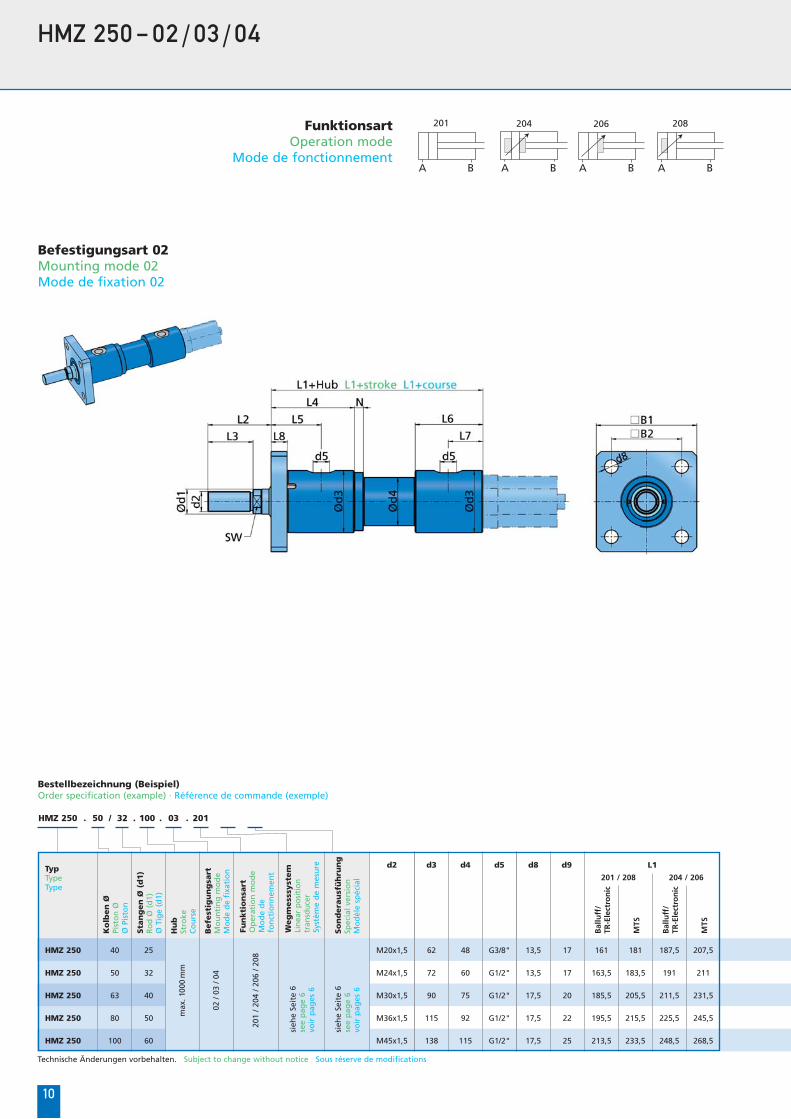
HMZ 250 – 02/03/04
Befestigungsart 02Mounting mode 02Mode de fixation 02
FunktionsartOperation mode
Mode de fonctionnement
204 206 208201
A B A B A B A B
Bestellbezeichnung (Beispiel)Order specification (example) · Référence de commande (exemple)
Technische Änderungen vorbehalten. Subject to change without notice Sous réserve de modifications
Ko
lben
ØPi
sto
n Ø
Ø P
isto
n
Hu
bSt
roke
Co
urs
e
Befe
stig
un
gsa
rtM
ou
nti
ng
mo
de
Mo
de
de
fixa
tio
n
So
nd
era
usf
üh
run
gSp
ecia
l ver
sio
nM
od
èle
spéc
ial
TypTypeType
d2
sieh
e Se
ite
6se
e p
age
6vo
ir p
ages
6
Sta
ng
en
Ø (
d1)
Ro
d Ø
(d
1)Ø
Tig
e (d
1)
max
. 100
0m
m
02 /
03 /
04
201
/ 204
/ 20
6 / 2
08
25
32
40
50
60
M20x1,5
M24x1,5
M30x1,5
M36x1,5
M45x1,5
d3
62
72
90
115
138
d4
48
60
75
92
115
d5
G3/8"
G1/2"
G1/2"
G1/2"
G1/2"
d8
13,5
13,5
17,5
17,5
17,5
d9
17
17
20
22
25
161
163,5
185,5
195,5
213,5
181
183,5
205,5
215,5
233,5
187,5
191
211,5
225,5
248,5
207,5
211
231,5
245,5
268,5
40HMZ 250
50HMZ 250
63HMZ 250
80HMZ 250
100HMZ 250
Fun
kti
on
sart
Op
erat
ion
mo
de
Mo
de
de
fon
ctio
nn
emen
t
Weg
mess
syst
em
Lin
ear
po
siti
on
tran
sdu
cer
Syst
ème
de
mes
ure
sieh
e Se
ite
6se
e p
age
6vo
ir p
ages
6
L1
201 / 208 204 / 206
Bal
luff
/TR
-Ele
ctro
nic
MTS
Bal
luff
/TR
-Ele
ctro
nic
MTS
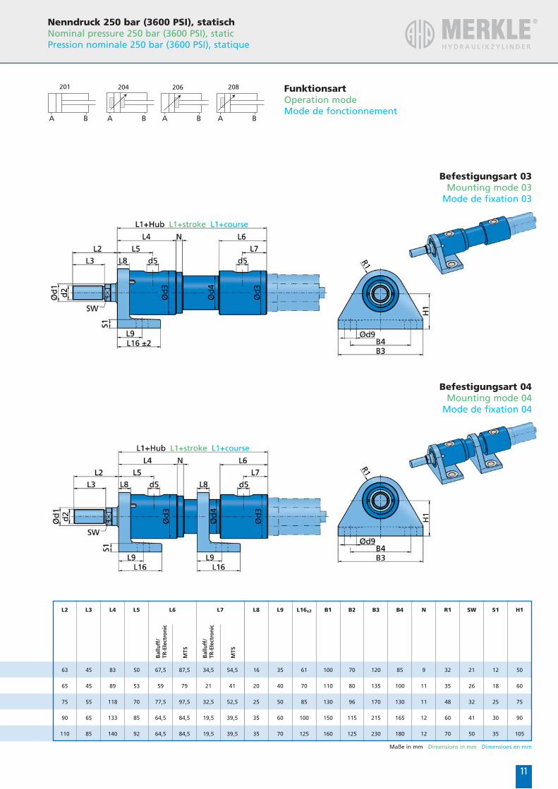
1111
Befestigungsart 03Mounting mode 03
Mode de fixation 03
FunktionsartOperation modeMode de fonctionnement
204 206 208201
A B A B A B A B
Befestigungsart 04Mounting mode 04
Mode de fixation 04
Nenndruck 250 bar (3600 PSI), statischNominal pressure 250 bar (3600 PSI), staticPression nominale 250 bar (3600 PSI), statique
Maße in mm Dimensions in mm Dimensions en mm
67,5
59
77,5
64,5
64,5
87,5
79
97,5
84,5
84,5
34,5
21
32,5
19,5
19,5
54,5
41
52,5
39,5
39,5
L2 L3 L4
83
89
118
133
140
45
45
55
65
85
63
65
75
90
110
L16±2 B1 B2
70
80
96
115
125
100
110
130
150
160
61
70
85
100
125
L9
35
40
50
60
70
L8
16
20
25
35
35
B3
120
135
170
215
230
B4
85
100
130
165
180
N
9
11
11
12
12
R1
32
35
48
60
70
SW
21
26
32
41
50
S1
12
18
25
30
35
H1
50
60
75
90
105
L5
50
53
70
85
92
L6 L7
Bal
luff
/TR
-Ele
ctro
nic
MTS
Bal
luff
/TR
-Ele
ctro
nic
MTS
HMZ 250 50. / 32 . 100 . 11 . 201 (L12 = xx mm)
12
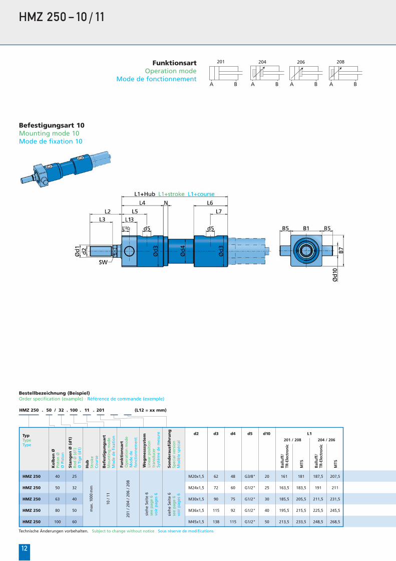
HMZ 250 – 10/ 11
FunktionsartOperation mode
Mode de fonctionnement
204 206 208201
A B A B A B A B
Bestellbezeichnung (Beispiel)Order specification (example) · Référence de commande (exemple)
Technische Änderungen vorbehalten. Subject to change without notice Sous réserve de modifications
Ko
lben
ØPi
sto
n Ø
Ø P
isto
n
Hu
bSt
roke
Co
urs
e
Befe
stig
un
gsa
rtM
ou
nti
ng
mo
de
Mo
de
de
fixa
tio
n
So
nd
era
usf
üh
run
gSp
ecia
l ver
sio
nM
od
èle
spéc
ial
TypTypeType
d2
Sta
ng
en
Ø (
d1)
Ro
d Ø
(d
1)Ø
Tig
e (d
1)
max
. 100
0m
m
201
/ 204
/ 20
6 / 2
08
25
32
40
50
60
M20x1,5
M24x1,5
M30x1,5
M36x1,5
M45x1,5
d3
62
72
90
115
138
d4
48
60
75
92
115
d5
G3/8"
G1/2"
G1/2"
G1/2"
G1/2"
d10
20
25
30
40
50
161
163,5
185,5
195,5
213,5
181
183,5
205,5
215,5
233,5
187,5
191
211,5
225,5
248,5
207,5
211
231,5
245,5
268,5
40HMZ 250
50HMZ 250
63HMZ 250
80HMZ 250
100HMZ 250
Fun
kti
on
sart
Op
erat
ion
mo
de
Mo
de
de
fon
ctio
nn
emen
t
Weg
mess
syst
em
Lin
ear
po
siti
on
tran
sdu
cer
Syst
ème
de
mes
ure
sieh
e Se
ite
6se
e p
age
6vo
ir p
ages
6
sieh
e Se
ite
6se
e p
age
6vo
ir p
ages
6
10 /
11
Befestigungsart 10Mounting mode 10Mode de fixation 10
L1
201 / 208 204 / 206
Bal
luff
/TR
-Ele
ctro
nic
MTS
Bal
luff
/TR
-Ele
ctro
nic
MTS
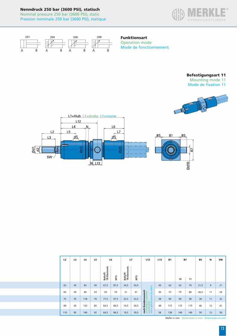
13
FunktionsartOperation modeMode de fonctionnement
204 206 208201
A B A B A B A B
Nenndruck 250 bar (3600 PSI), statischNominal pressure 250 bar (3600 PSI), staticPression nominale 250 bar (3600 PSI), statique
Maße in mm Dimensions in mm Dimensions en mm
10 11
67,5
59
77,5
64,5
64,5
87,5
79
97,5
84,5
84,5
34,5
21
32,5
19,5
19,5
54,5
41
52,5
39,5
39,5
L2 L3 L4
83
89
118
133
140
45
45
55
65
85
63
65
75
90
110
B1L13L12 B7
70
80
90
115
140
62
75
90
115
140
62
72
90
115
138
B5
21,5
26,5
30
40
50
N
9
11
11
12
12
SW
21
26
32
41
50
L5
30
30
38
48
58
50
53
70
85
92 nac
h K
un
den
wu
nsc
hac
cord
ing
to c
usto
mer
spec
ific
atio
nse
lon
spéc
ific
atio
n du
clie
nt
Befestigungsart 11Mounting mode 11
Mode de fixation 11
L6 L7
Bal
luff
/TR
-Ele
ctro
nic
MTS
Bal
luff
/TR
-Ele
ctro
nic
MTS
14
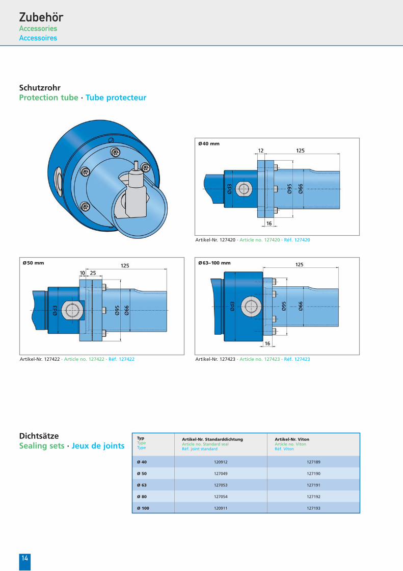
ZubehörAccessories
Accessoires
SchutzrohrProtection tube · Tube protecteur
DichtsätzeSealing sets · Jeux de joints
TypTypeType
Artikel-Nr. StandarddichtungArticle no. Standard sealRéf. joint standard
120912
127049
127053
127054
120911
Artikel-Nr. VitonArticle no. VitonRéf. Viton
127189
127190
127191
127192
127193
Ø 40
Ø 50
Ø 63
Ø 80
Ø 100
Artikel-Nr. 127420 · Article no. 127420 · Réf. 127420
Ø40 mm
Artikel-Nr. 127422 · Article no. 127422 · Réf. 127422
Ø50 mm
Artikel-Nr. 127423 · Article no. 127423 · Réf. 127423
Ø63–100 mm

CD-Updates
available at
update.ahp.de
Bestellen Sie Ihren persönlichen CAD-Assistenten direkt bei AHP Merkle.Order your personal CAD Assistant directly from AHP Merkle.Commandez vos assistants CAO personnalisés directement auprès de AHP Merkle.
Bewegen Sie sich in einer neuen DimensionEnter a new dimension Déplacez-vous dans une nouvelle dimension
CAD-AssistentCAD Assistant Assistant CAO
ZylindervorschlagCylinder proposal Propositions de vérins
UpdatefunktionUpdate function Fonction de mise à jour

AHP Merkle GmbH • Eschenweg 1-4 • D-79232 March
Fon +49 (0) 7665 / 4208-0 • Fax +49 (0) 7665 / 4208-88 • E-Mail: [email protected]
ww
w.a
gen
tur-
kies
ewet
ter.d
e