Embed Size (px)
Citation preview
AP Physics C: Emag 1999-‐2012
Compiled by: Tobore Tasker
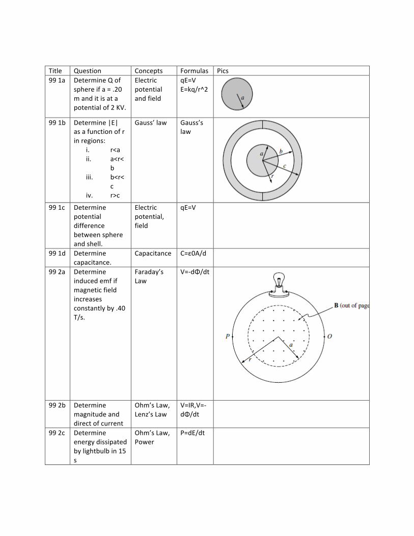
Title Question Concepts Formulas Pics 99 1a Determine Q of
sphere if a = .20 m and it is at a potential of 2 KV.
Electric potential and field
qE=V E=kq/r^2
99 1b Determine |E|
as a function of r in regions:
i. r<a ii. a<r<
b iii. b<r<
c iv. r>c
Gauss’ law Gauss’s law
99 1c Determine
potential difference between sphere and shell.
Electric potential, field
qE=V
99 1d Determine capacitance.
Capacitance C=ε0A/d
99 2a Determine induced emf if magnetic field increases constantly by .40 T/s.
Faraday’s Law
V=-‐dΦ/dt
99 2b Determine
magnitude and direct of current
Ohm’s Law, Lenz’s Law
V=IR,V=-‐ dΦ/dt
99 2c Determine energy dissipated by lightbulb in 15 s
Ohm’s Law, Power
P=dE/dt
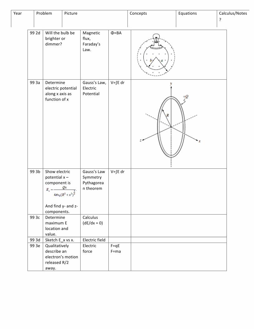
99 2d Will the bulb be brighter or dimmer?
Magnetic flux, Faraday’s Law.
Φ=BA
99 3a Determine
electric potential along x axis as function of x
Gauss’s Law, Electric Potential
V=∫E dr
99 3b Show electric
potential x –component is
And find y-‐ and z-‐ components.
Gauss’s Law Symmetry Pythagorean theorem
V=∫E dr
99 3c Determine maximum E location and value.
Calculus (dE/dx = 0)
99 3d Sketch E_x vs x. Electric field 99 3e Qualitatively
describe an electron’s motion released R/2 away.
Electric force
F=qE F=ma
Year Problem Picture Concepts Equations Calculus/Notes?
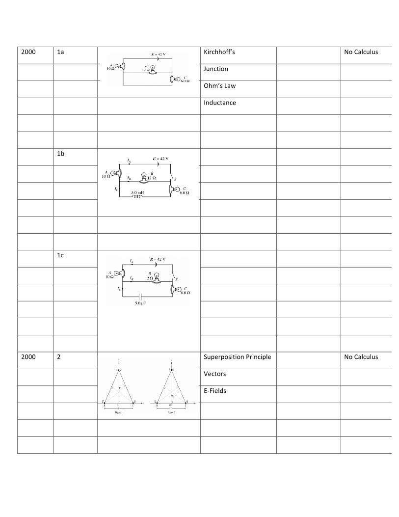
2000 1a Kirchhoff’s No Calculus
Junction
Ohm’s Law
Inductance
1b
1c
2000 2 Superposition Principle No Calculus
Vectors
E-‐Fields
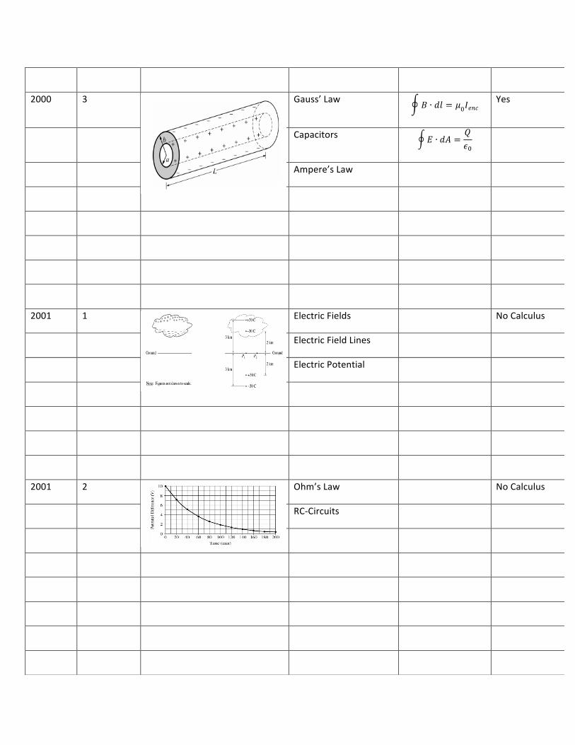
2000 3 Gauss’ Law 𝐵 ∙ 𝑑𝑙 = 𝜇0𝐼𝑒𝑛𝑐 Yes
Capacitors 𝐸 ∙ 𝑑𝐴 =𝑄𝜖!
Ampere’s Law
2001 1 Electric Fields No Calculus
Electric Field Lines
Electric Potential
2001 2 Ohm’s Law No Calculus
RC-‐Circuits
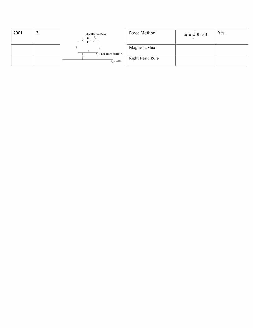
2001 3 Force Method 𝜙 = 𝐵 ∙ 𝑑𝐴 Yes
Magnetic Flux
Right Hand Rule
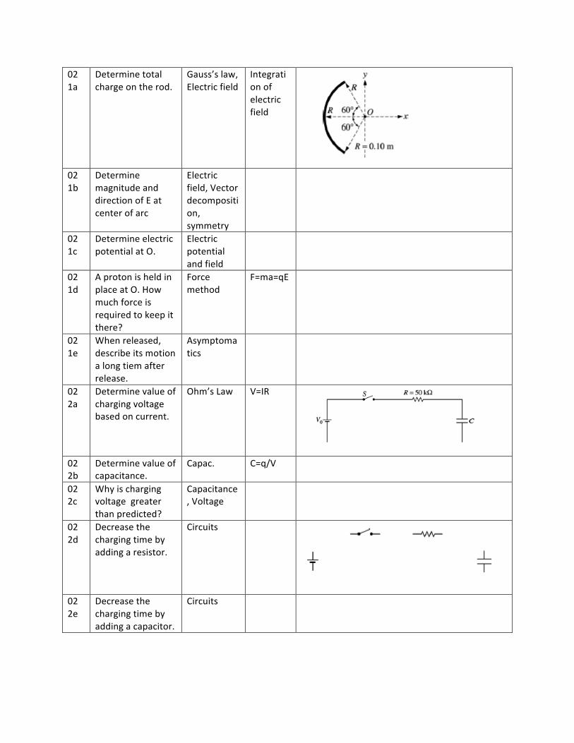
02 1a
Determine total charge on the rod.
Gauss’s law, Electric field
Integration of electric field
02 1b
Determine magnitude and direction of E at center of arc
Electric field, Vector decomposition, symmetry
02 1c
Determine electric potential at O.
Electric potential and field
02 1d
A proton is held in place at O. How much force is required to keep it there?
Force method
F=ma=qE
02 1e
When released, describe its motion a long tiem after release.
Asymptomatics
02 2a
Determine value of charging voltage based on current.
Ohm’s Law V=IR
02 2b
Determine value of capacitance.
Capac. C=q/V
02 2c
Why is charging voltage greater than predicted?
Capacitance, Voltage
02 2d
Decrease the charging time by adding a resistor.
Circuits
02 2e
Decrease the charging time by adding a capacitor.
Circuits
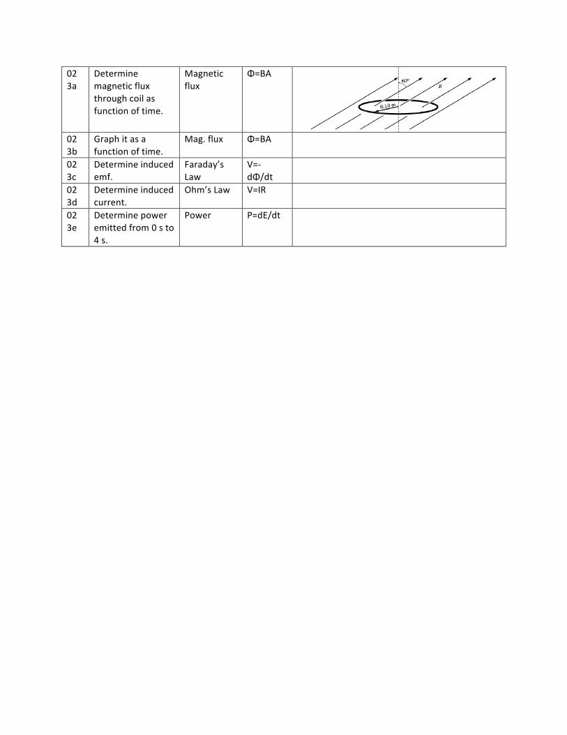
02 3a
Determine magnetic flux through coil as function of time.
Magnetic flux
Φ=BA
02 3b
Graph it as a function of time.
Mag. flux Φ=BA
02 3c
Determine induced emf.
Faraday’s Law
V=-‐ dΦ/dt
02 3d
Determine induced current.
Ohm’s Law V=IR
02 3e
Determine power emitted from 0 s to 4 s.
Power P=dE/dt
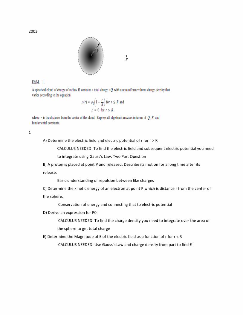
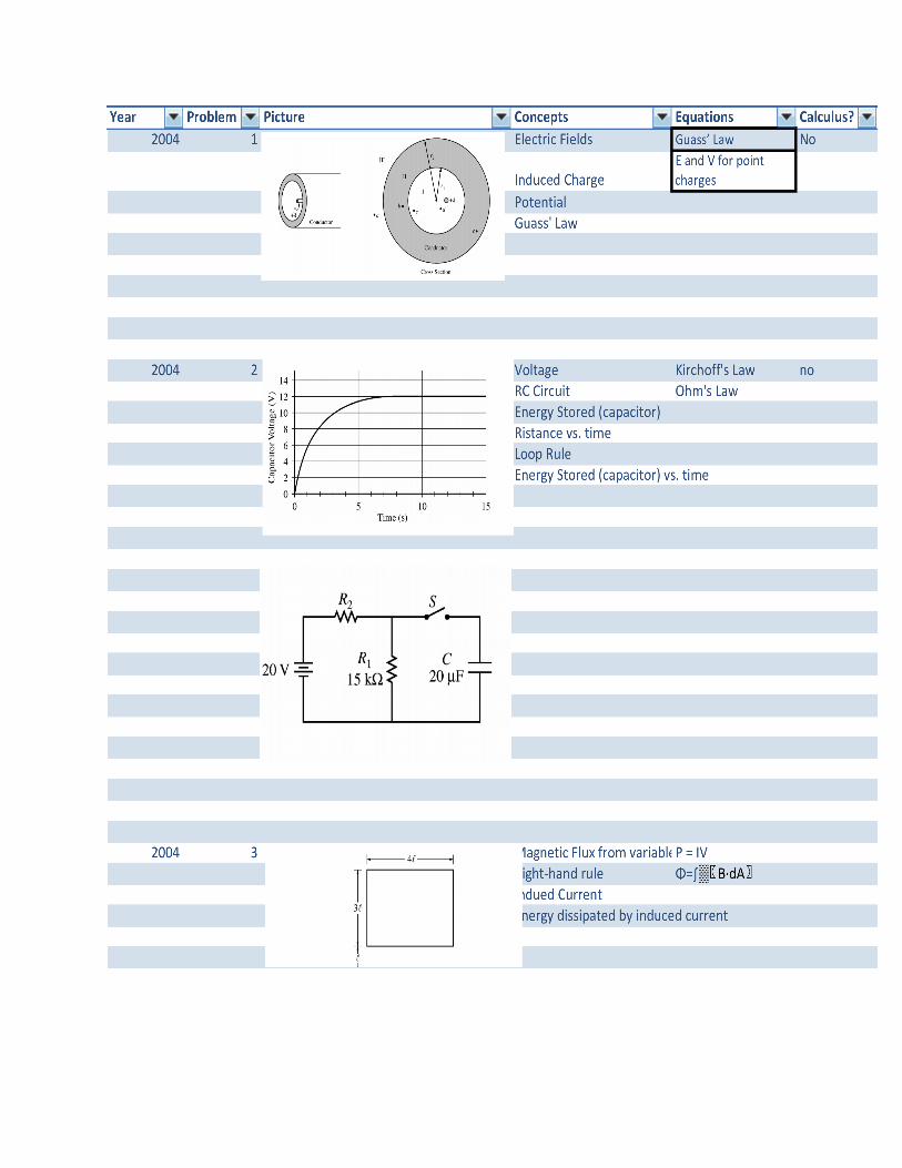
2003
1
A) Determine the electric field and electric potential of r for r > R
CALCULUS NEEDED: To find the electric field and subsequent electric potential you need
to integrate using Gauss's Law. Two Part Question
B) A proton is placed at point P and released. Describe its motion for a long time after its
release.
Basic understanding of repulsion between like charges
C) Determine the kinetic energy of an electron at point P which is distance r from the center of
the sphere.
Conservation of energy and connecting that to electric potential
D) Derive an expression for P0
CALCULUS NEEDED: To find the charge density you need to integrate over the area of
the sphere to get total charge
E) Determine the Magnitude of E of the electric field as a function of r for r < R
CALCULUS NEEDED: Use Gauss's Law and charge density from part to find E
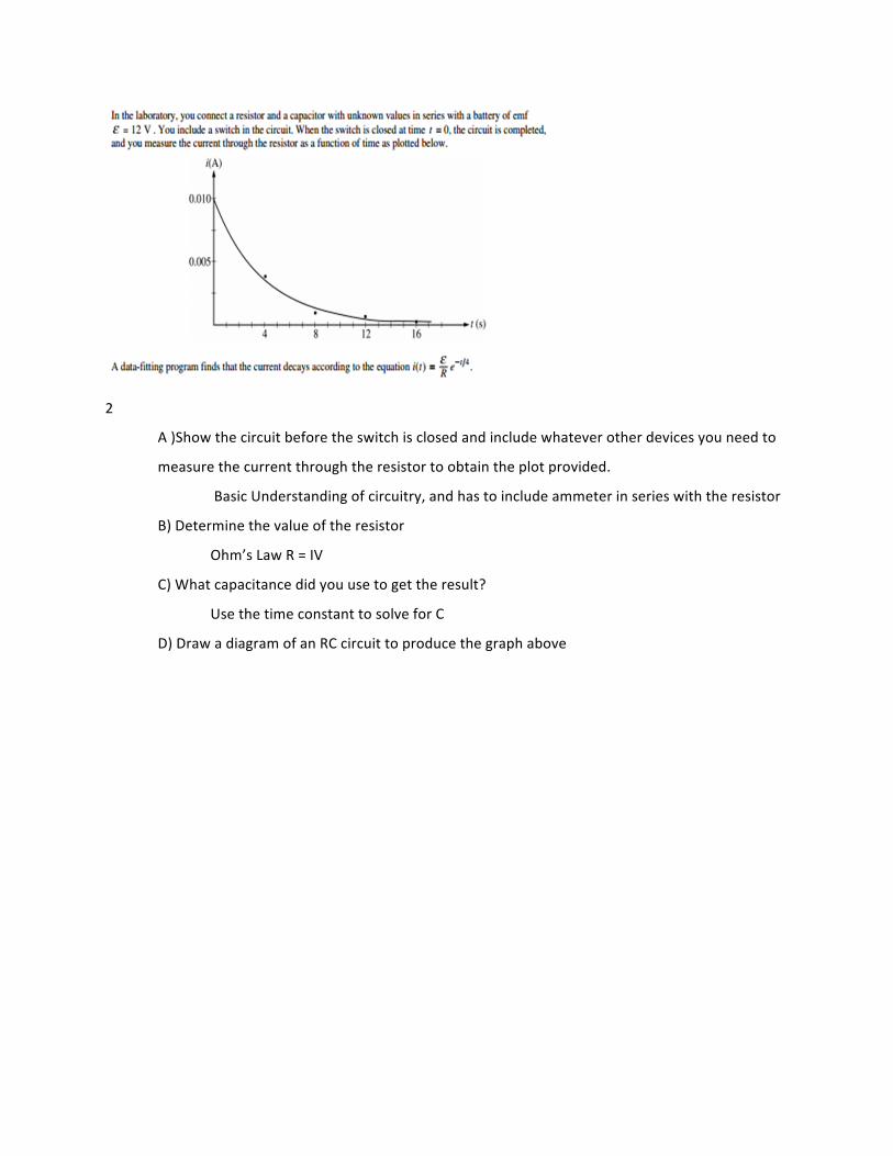
2
A )Show the circuit before the switch is closed and include whatever other devices you need to
measure the current through the resistor to obtain the plot provided.
Basic Understanding of circuitry, and has to include ammeter in series with the resistor
B) Determine the value of the resistor
Ohm’s Law R = IV
C) What capacitance did you use to get the result?
Use the time constant to solve for C
D) Draw a diagram of an RC circuit to produce the graph above
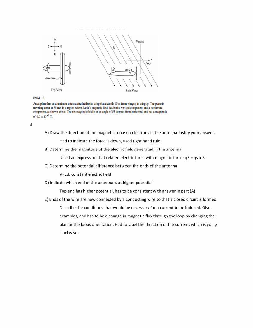
3
A) Draw the direction of the magnetic force on electrons in the antenna Justify your answer.
Had to indicate the force is down, used right hand rule
B) Determine the magnitude of the electric field generated in the antenna
Used an expression that related electric force with magnetic force: qE = qv x B
C) Determine the potential difference between the ends of the antenna
V=Ed, constant electric field
D) Indicate which end of the antenna is at higher potential
Top end has higher potential, has to be consistent with answer in part (A)
E) Ends of the wire are now connected by a conducting wire so that a closed circuit is formed
Describe the conditions that would be necessary for a current to be induced. Give
examples, and has to be a change in magnetic flux through the loop by changing the
plan or the loops orientation. Had to label the direction of the current, which is going
clockwise.
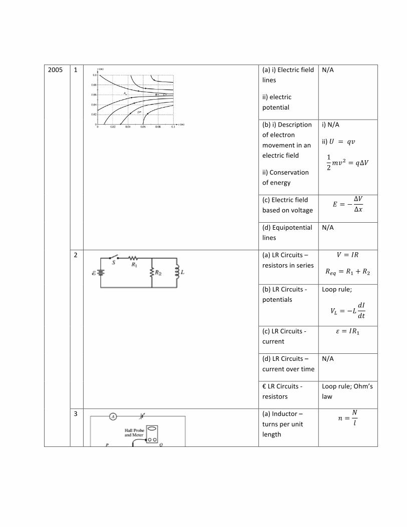
2005 1
(a) i) Electric field lines
ii) electric potential
N/A
(b) i) Description of electron movement in an electric field
ii) Conservation of energy
i) N/A
ii) 𝑈 = 𝑞𝑣
12𝑚𝑣! = 𝑞∆𝑉
(c) Electric field based on voltage
𝐸 = −∆𝑉∆𝑥
(d) Equipotential lines
N/A
2
(a) LR Circuits – resistors in series
𝑉 = 𝐼𝑅
𝑅!" = 𝑅! + 𝑅!
(b) LR Circuits -‐ potentials
Loop rule;
𝑉! = −𝐿𝑑𝐼𝑑𝑡
(c) LR Circuits -‐ current
𝜀 = 𝐼𝑅!
(d) LR Circuits – current over time
N/A
€ LR Circuits -‐ resistors
Loop rule; Ohm’s law
3
(a) Inductor – turns per unit length
𝑛 =𝑁𝑙
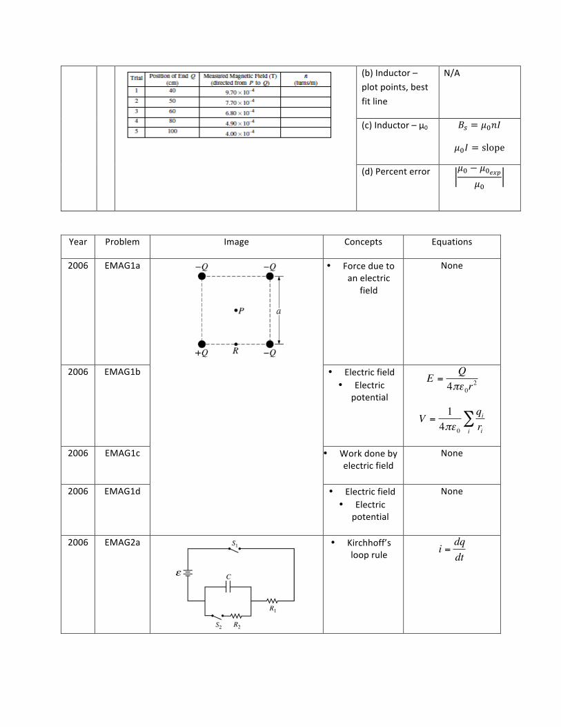
(b) Inductor – plot points, best fit line
N/A
(c) Inductor – μ0 𝐵! = 𝜇!𝑛𝐼
𝜇!𝐼 = slope
(d) Percent error 𝜇! − 𝜇!!"#𝜇!
Year Problem Image Concepts Equations
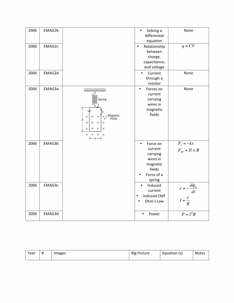
2006 EMAG1a
• Force due to an electric
field
None
2006 EMAG1b • Electric field • Electric
potential
2006 EMAG1c • Work done by electric field
None
2006 EMAG1d • Electric field • Electric
potential
None
2006 EMAG2a
• Kirchhoff’s loop rule
€
E =Q
4πε 0r2
€
V =14πε 0
qirii
∑
€
i =dqdt
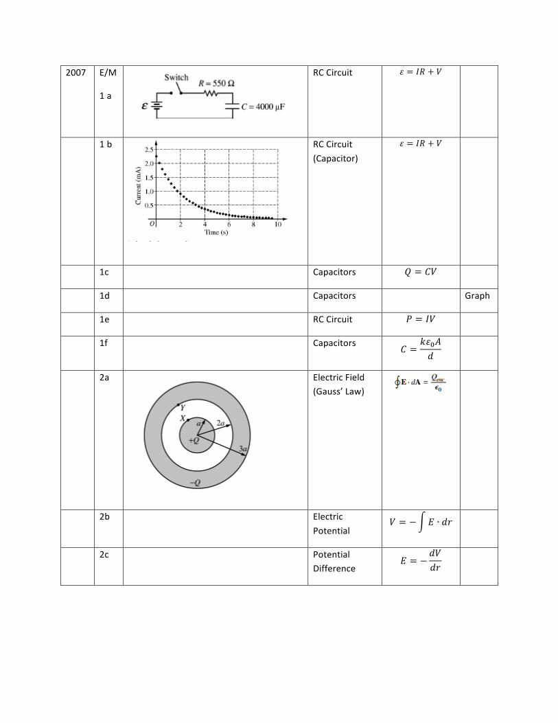
2006 EMAG2b • Solving a differential equation
None
2006 EMAG2c • Relationship between charge,
capacitance, and voltage
2006 EMAG2d • Current through a resistor
None
2006 EMAG3a
• Forces on current carrying wires in magnetic fields
None
2006 EMAG3b • Force on current carrying wires in magnetic fields
• Force of a spring
2006 EMAG3c • Induced current
• Induced EMF • Ohm’s Law
2006 EMAG3d • Power
Year # Images Big Picture Equation (s) Notes
€
q = CV
€
Fs = −kxFM = Il × B
€
ε = −dφmdt
I =εR
€
P = I2R
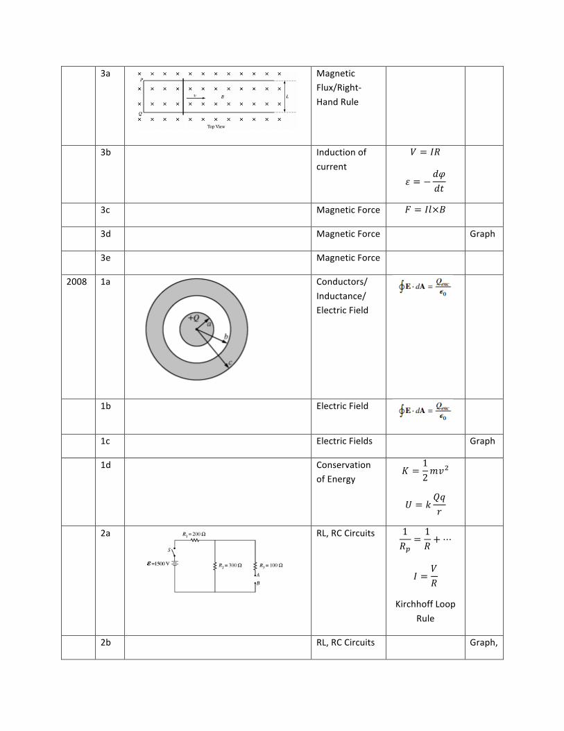
2007 E/M
1 a
RC Circuit 𝜀 = 𝐼𝑅 + 𝑉
1 b
RC Circuit (Capacitor)
𝜀 = 𝐼𝑅 + 𝑉
1c Capacitors 𝑄 = 𝐶𝑉
1d Capacitors Graph
1e RC Circuit 𝑃 = 𝐼𝑉
1f Capacitors 𝐶 =𝑘𝜀!𝐴𝑑
2a
Electric Field (Gauss’ Law)
2b Electric Potential
𝑉 = − 𝐸 ∙ 𝑑𝑟
2c Potential Difference
𝐸 = −𝑑𝑉𝑑𝑟
3a
Magnetic Flux/Right-‐Hand Rule
3b Induction of current
𝑉 = 𝐼𝑅
𝜀 = −𝑑𝜑𝑑𝑡
3c Magnetic Force 𝐹 = 𝐼𝑙×𝐵
3d Magnetic Force Graph
3e Magnetic Force
2008 1a
Conductors/ Inductance/ Electric Field
1b Electric Field
1c Electric Fields Graph
1d Conservation of Energy
𝐾 =12𝑚𝑣!
𝑈 = 𝑘𝑄𝑞𝑟
2a
RL, RC Circuits 1𝑅!
=1𝑅+⋯
𝐼 =𝑉𝑅
Kirchhoff Loop Rule
2b RL, RC Circuits Graph,
Exponential vs Linear Trends
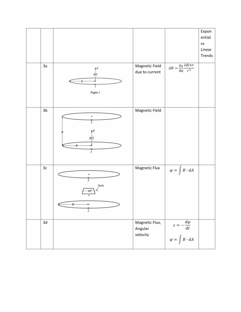
3a
Magnetic Field due to current
𝑑𝐵 =𝜇!4𝜋
𝐼𝑑𝑙×𝑟𝑟!
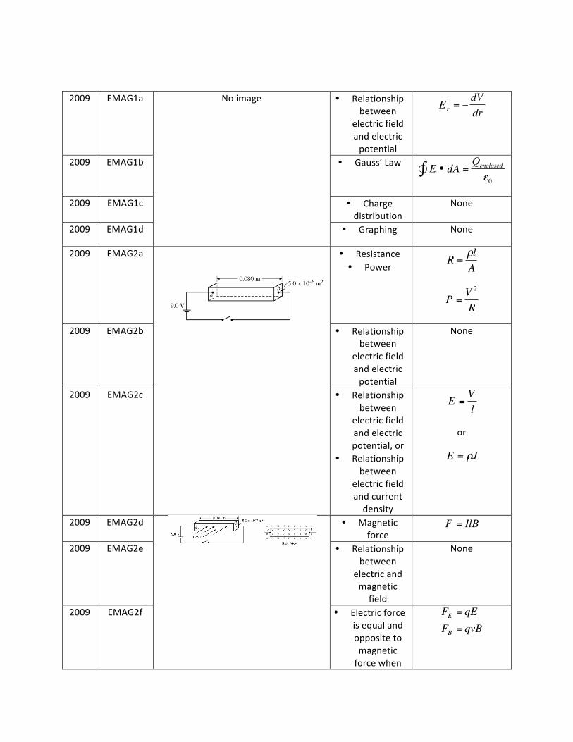
3b
Magnetic Field
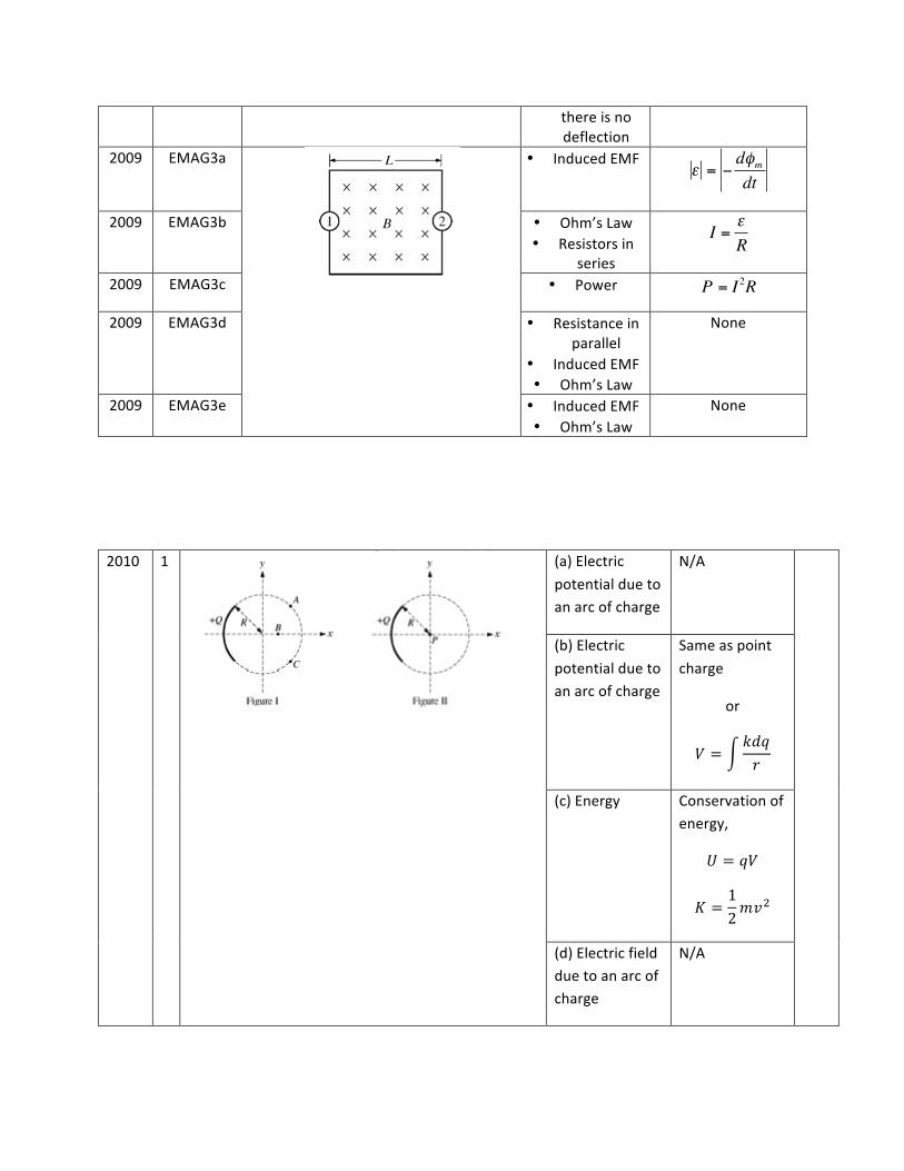
3c
Magnetic Flux 𝜑 = 𝐵 ∙ 𝑑𝐴
3d Magnetic Flux, Angular velocity
𝜀 = −𝑑𝜑𝑑𝑡
𝜑 = 𝐵 ∙ 𝑑𝐴
2009 EMAG1a No image
• Relationship between
electric field and electric potential
€
Er = −dVdr
2009 EMAG1b • Gauss’ Law
€
E • dA =Qenclosed
ε0∫
2009 EMAG1c • Charge distribution
None
2009 EMAG1d • Graphing None
2009 EMAG2a
• Resistance • Power
€
R =ρlA
€
P =V 2
R
2009 EMAG2b • Relationship between
electric field and electric potential
None
2009 EMAG2c • Relationship between
electric field and electric potential, or
• Relationship between
electric field and current density
€
E =Vl
or
€
E = ρJ
2009 EMAG2d
• Magnetic force
€
F = IlB
2009 EMAG2e • Relationship between
electric and magnetic field
None
2009 EMAG2f • Electric force is equal and opposite to magnetic force when
€
FE = qEFB = qvB
there is no deflection
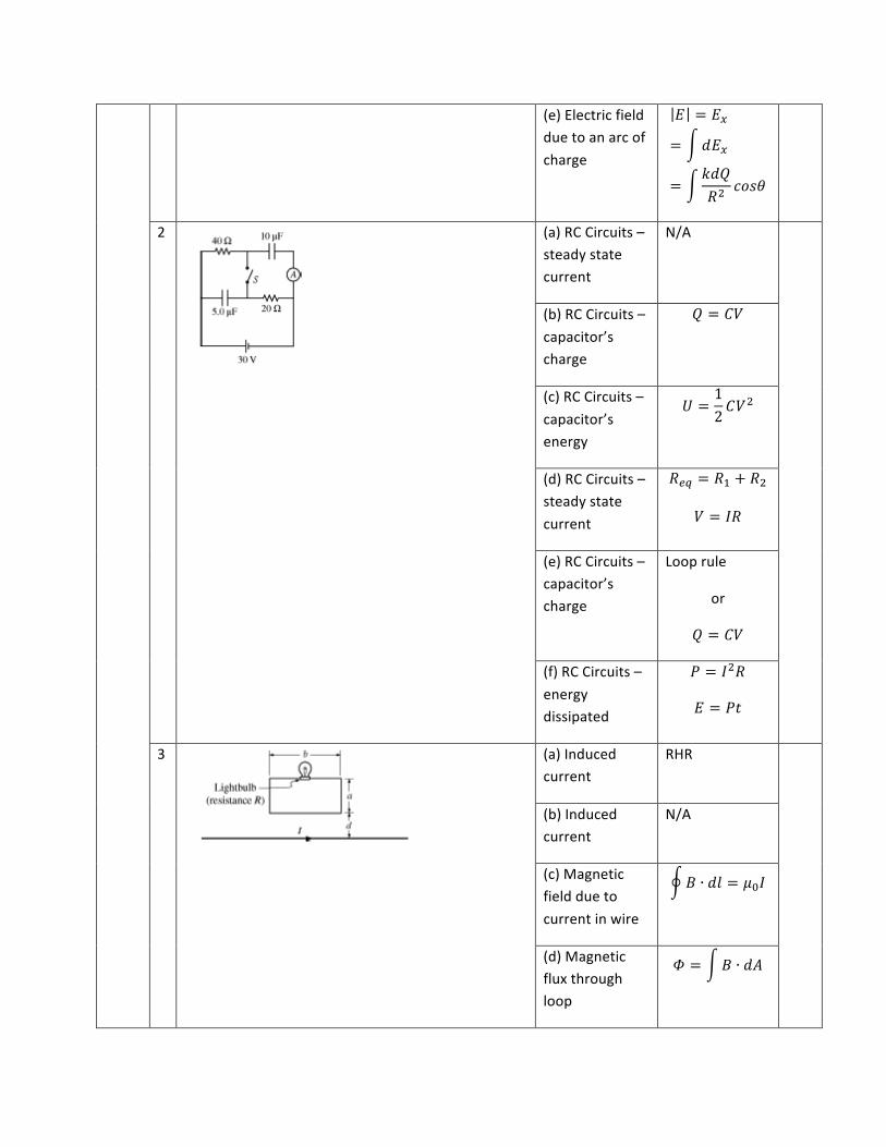
2009 EMAG3a
• Induced EMF
€
ε = −dφmdt
2009 EMAG3b • Ohm’s Law • Resistors in
series
€
I =εR
2009 EMAG3c • Power
2009 EMAG3d • Resistance in parallel
• Induced EMF • Ohm’s Law
None
2009 EMAG3e • Induced EMF • Ohm’s Law
None
2010 1
(a) Electric potential due to an arc of charge
N/A
(b) Electric potential due to an arc of charge
Same as point charge
or
𝑉 =𝑘𝑑𝑞𝑟
(c) Energy Conservation of energy,
𝑈 = 𝑞𝑉
𝐾 =12𝑚𝑣!
(d) Electric field due to an arc of charge
N/A
€
P = I2R
(e) Electric field due to an arc of charge
𝐸 = 𝐸!
= 𝑑𝐸!
=𝑘𝑑𝑄𝑅!
𝑐𝑜𝑠𝜃
2
(a) RC Circuits – steady state current
N/A
(b) RC Circuits – capacitor’s charge
𝑄 = 𝐶𝑉
(c) RC Circuits – capacitor’s energy
𝑈 =12𝐶𝑉!
(d) RC Circuits – steady state current
𝑅!" = 𝑅! + 𝑅!
𝑉 = 𝐼𝑅
(e) RC Circuits – capacitor’s charge
Loop rule
or
𝑄 = 𝐶𝑉
(f) RC Circuits – energy dissipated
𝑃 = 𝐼!𝑅
𝐸 = 𝑃𝑡
3
(a) Induced current
RHR
(b) Induced current
N/A
(c) Magnetic field due to current in wire
𝐵 ∙ 𝑑𝑙 = 𝜇!𝐼
(d) Magnetic flux through loop
𝛷 = 𝐵 ∙ 𝑑𝐴
(e) Power dissipated
𝑃 = 𝑉!/𝑅
𝑉 = 𝜀 = −𝑑𝛷𝑑𝑡
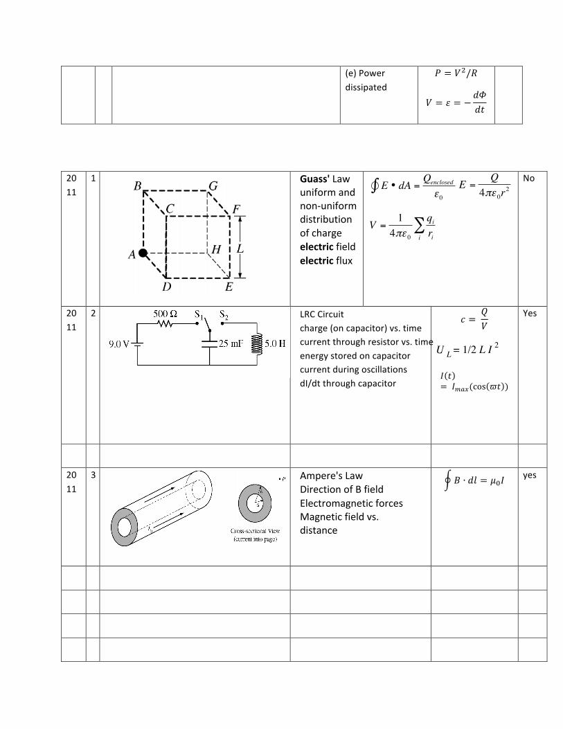
2011
1
Guass' Law uniform and non-‐uniform distribution of charge electric field electric flux
€
E • dA =Qenclosed
ε0∫
No
2011
2
LRC Circuit charge (on capacitor) vs. time current through resistor vs. time energy stored on capacitor current during oscillations dI/dt through capacitor
𝑐 = 𝑄𝑉
U L = 1/2 L I 2
𝐼 𝑡= 𝐼!"#(cos 𝜛𝑡 )
Yes
2011
3
Ampere's Law Direction of B field Electromagnetic forces Magnetic field vs. distance
𝐵 ∙ 𝑑𝑙 = 𝜇!𝐼 yes
€
E =Q
4πε 0r2
€
V =14πε 0
qirii
∑
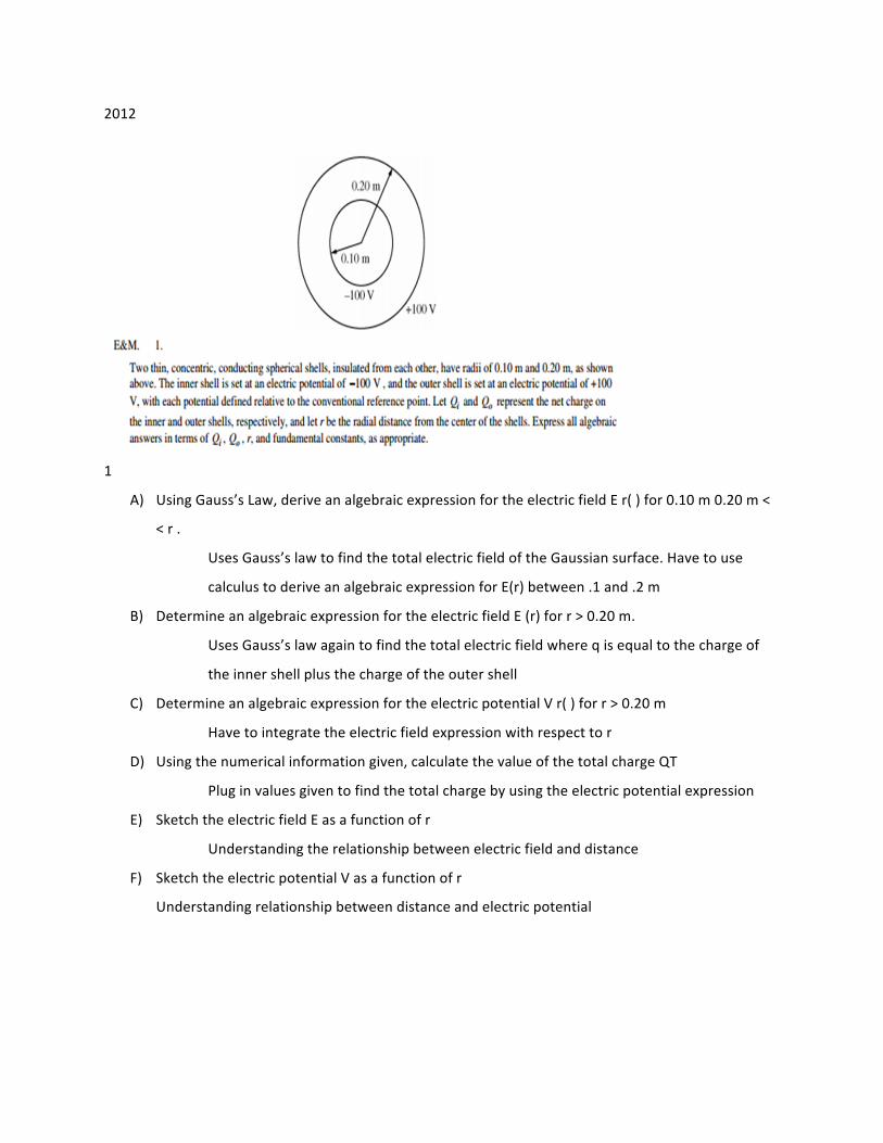
2012
1
A) Using Gauss’s Law, derive an algebraic expression for the electric field E r( ) for 0.10 m 0.20 m <
< r .
Uses Gauss’s law to find the total electric field of the Gaussian surface. Have to use
calculus to derive an algebraic expression for E(r) between .1 and .2 m
B) Determine an algebraic expression for the electric field E (r) for r > 0.20 m.
Uses Gauss’s law again to find the total electric field where q is equal to the charge of
the inner shell plus the charge of the outer shell
C) Determine an algebraic expression for the electric potential V r( ) for r > 0.20 m
Have to integrate the electric field expression with respect to r
D) Using the numerical information given, calculate the value of the total charge QT
Plug in values given to find the total charge by using the electric potential expression
E) Sketch the electric field E as a function of r
Understanding the relationship between electric field and distance
F) Sketch the electric potential V as a function of r
Understanding relationship between distance and electric potential
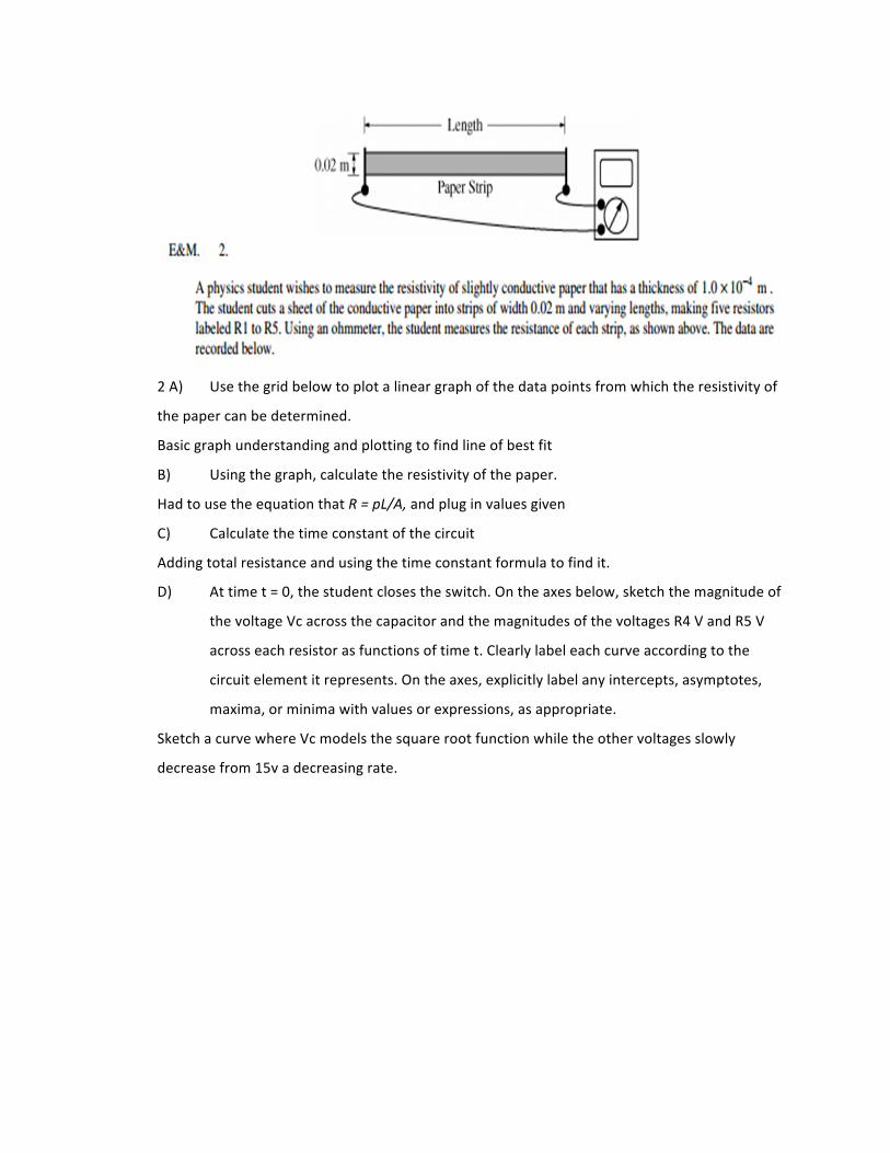
2 A) Use the grid below to plot a linear graph of the data points from which the resistivity of
the paper can be determined.
Basic graph understanding and plotting to find line of best fit
B) Using the graph, calculate the resistivity of the paper.
Had to use the equation that R = pL/A, and plug in values given
C) Calculate the time constant of the circuit
Adding total resistance and using the time constant formula to find it.
D) At time t = 0, the student closes the switch. On the axes below, sketch the magnitude of
the voltage Vc across the capacitor and the magnitudes of the voltages R4 V and R5 V
across each resistor as functions of time t. Clearly label each curve according to the
circuit element it represents. On the axes, explicitly label any intercepts, asymptotes,
maxima, or minima with values or expressions, as appropriate.
Sketch a curve where Vc models the square root function while the other voltages slowly
decrease from 15v a decreasing rate.
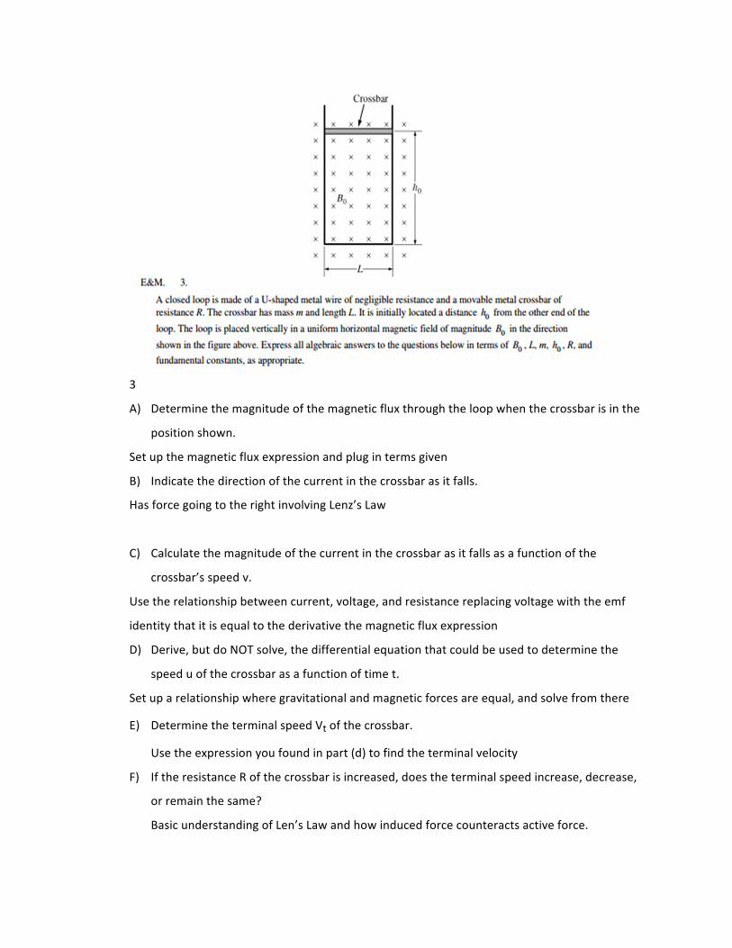
3
A) Determine the magnitude of the magnetic flux through the loop when the crossbar is in the
position shown.
Set up the magnetic flux expression and plug in terms given
B) Indicate the direction of the current in the crossbar as it falls.
Has force going to the right involving Lenz’s Law
C) Calculate the magnitude of the current in the crossbar as it falls as a function of the
crossbar’s speed v.
Use the relationship between current, voltage, and resistance replacing voltage with the emf
identity that it is equal to the derivative the magnetic flux expression
D) Derive, but do NOT solve, the differential equation that could be used to determine the
speed u of the crossbar as a function of time t.
Set up a relationship where gravitational and magnetic forces are equal, and solve from there
E) Determine the terminal speed Vt of the crossbar.
Use the expression you found in part (d) to find the terminal velocity
F) If the resistance R of the crossbar is increased, does the terminal speed increase, decrease,
or remain the same?
Basic understanding of Len’s Law and how induced force counteracts active force.