Embed Size (px)
DESCRIPTION
audiofire
Citation preview
AUDIOFIRE™
2
AUDIOFIRE™
4
AUDIOFIRE™
8
AUDIOFIRE™
12
사용설명서 2.0 Windows 용
중요 안전수칙 1. 설명서 숙지– 제품을 사용하기전에 모든 안전 / 작동 수칙을 읽기 바랍니다. 2. 설명서 보관 – 안전수칙과 사용설명서는 차후 참고를 위해 잘 보관하시기 바랍니다. 3. 주의사항 숙지 – ECHO 제품과 설명서에 기재된 경고와 주의사항을 주의하시고 염두해
두시길 바랍니다. 4. 수칙 따르기 – 모든 작동과 사용은 설명서에 있는 수칙들을 따르시기 바랍니다. 5. 습기 – 물과 습기는 ECHO 제품에 좋지않고 해를 끼칠 수 있습니다. 싱크, 습한 지하,
비가새는 지붕쪽등 물과 습기가 다분한 곳에서 제품의 설치를 금합니다. 6. 열 – 히터나 방열제품 근처로부터 제품을 멀리하시길 바랍니다. 7. 전원 공급원 – 제품은 설명서에 기재된 타입의 전원 공급원을 반드시 사용해야 합니다.
제품을 사용하려는 지역의 전원공급원에 대해 확신이 서지 않으실때는 그 지역의
전력회사에 문의하시길 바랍니다. 8. 접지 – 제품의 접지기능이 저하되거나 방해되지 않게 주의를 기울이셔야 합니다.
제품은 접지 컨덕터와 플러그가 장착된 전원 케이블과 같이 제공됩니다. 이 플러그는 그
지역의 기본 규격과 수칙에 알맞게 접지되어있는 콘센트에 꼽아져야됩니다. 제품과 같이
제공되는 플러그를 임의로 변경하지 마시기 바랍니다. 만약 플러그가 콘센트에 알맞지
않은경우엔, 전기전문가에 설치를 요청하시기 바랍니다. 9. 전원 케이블 보호 – 전원 케이블은 걸어서 지나갈때 또는 물건들이 위에 놓여지는것을
방지할 수 있게 정돈되어야합니다. 특히, 플러그, 콘센트, 그리고 케이블이 제품에서
빠져나오는 부분에 각별한 주의를 하시기 바랍니다. 10. 수리 – 제품을 임의로 분해하는 것은 치명적인 감전이나 충격에 노출을 불러일으 킬 수
있으니 스스로 수리를 시도하는 것을 금합니다. 모든 점검 및 수리는 검증받은 서비스
센터 나 전문가에게 문의하셔야 합니다.
11. 제품의 손상에 의한 수리 – 다음과 같은 일이 발생했을 때에 제품을 콘센트에서
분리하시고 서비스 센터나 전문가에게 문의합니다:
a) 제품이 떨어져 충격을 받거나 액체를 제품에 엎지렀을 경우
b) 제품이 비나 물에 노출되었을 경우
c) 제품이 정상적으로 작동하지 않거나 성능저하가 눈에 띄게 보일경우
d) 제품이 떨어지거나 손상되었을 경우
Registering your product online at http://www.ECHOaudio.com/support/register.php allows us to register key information so that we may handle problems faster and inform you of advance information on upgrades and other news. Thank you in advance for registering. We hope you enjoy your ECHO product.
Limited Warranty ECHO Digital Audio Corporation warrants this product, when purchased at an Authorized ECHO Dealer in the United States of America, to be free of defects in materials and manufacturing workmanship for a period of one year from the date of original purchase. During the warranty period ECHO shall, at its option, either repair or replace any product that proves to be defective upon inspection by ECHO. Final determination of warranty coverage lies solely with ECHO. ECHO reserves the right to update any unit returned for repair, and reserves the right to change or improve the design of the product at any time without notice. This is your sole warranty. ECHO does not authorize any third party, including any dealer or sales representative, to assume any liability on behalf of ECHO or to make any warranty for ECHO. Service and repairs of ECHO products are to be performed only at the factory (see below) unless otherwise authorized in advance by the ECHO Service Department. Unauthorized service, repair or modification will void this warranty. To obtain factory service: Contact ECHO Digital Audio Corporation at (805) 684-4593, 9AM to 4PM Monday through Friday (Pacific Time). If necessary, you will be given a return authorization number. Products returned without an RA number will be refused. ECHO may, at its option, require proof of the original date of purchase in the form of a dated copy of the original authorized dealer’s invoice or sales receipt. Pack the product in its original shipping carton and attach a description of the problem along with your name and a phone number where ECHO can contact you if necessary. Ship the product insured and freight prepaid to:
ECHO Digital Audio Corporation 6450 Via Real Suite 1
Carpinteria, CA 93013
DISCLAIMER AND LIMITATION OF WARRANTY ECHO makes no other warranties, express, implied, or otherwise, regarding ECHO products, and specifically disclaims any warranty for merchantability or fitness for a particular purpose. The exclusion of implied warranties is not permitted in some states and the exclusions specified herein may not apply to you. This warranty provides you with specific legal rights. There may be other rights that you have which vary from state to state. In no event will ECHO be liable for any lost profits, or for any consequential, direct or indirect damages, however caused and on any theory of liability, arising from this warranty and sale.
©2006 by ECHO Digital Audio Corporation 6450 Via Real Suite 1 Carpinteria, CA 93013 ECHO® and AudioFire™ are trademarks of ECHO Digital Audio Corporation. FireWire® is a trademark of Apple Computer, Inc. Tracktion™ is a trademark of LOUD Technologies Inc. Windows® and Windows XP® are registered trademarks of Microsoft, Inc.
INTRODUCTION (소개).......................................오류! 책갈피가 정의되어 있지 않습니다.
제품을 받고나서 해야될 일.................................... 오류! 책갈피가 정의되어 있지 않습니다.
권장 사양 ...................................................................... 오류! 책갈피가 정의되어 있지 않습니다.
INSTALLATION (설치) ........................................................................................................... 9
관리자로 로그인 하기 .............................................. 오류! 책갈피가 정의되어 있지 않습니다.
소프트웨어 최신버전 체크하기............................ 오류! 책갈피가 정의되어 있지 않습니다.
AUDIOFIRE 하드웨어와 소프트웨어 설치하기 ... 오류! 책갈피가 정의되어 있지 않습니다.
오디오 인터페이스에 연결하기........................................................................................................12
TRACKTION 1 설치하기............................................... 오류! 책갈피가 정의되어 있지 않습니다.
TRACKTION 실행 및 인/아웃풋 지정하기............. 오류! 책갈피가 정의되어 있지 않습니다.
CONSOLE (콘솔)...................................................................................................................26
콘솔 실행하기 ............................................................. 오류! 책갈피가 정의되어 있지 않습니다.
자동 플래쉬 업데이트 .......................................................................................................................... 27
콘솔 창........................................................................... 오류! 책갈피가 정의되어 있지 않습니다.
버스 채널 선택하기................................................... 오류! 책갈피가 정의되어 있지 않습니다.
마스터 아웃 버스 컨트롤......................................... 오류! 책갈피가 정의되어 있지 않습니다.
아날로그 인풋 ............................................................. 오류! 책갈피가 정의되어 있지 않습니다.
디지털 인풋 (AUDIOFIRE2, AUDIOFIRE4 AND AUDIOFIRE8) ....오류! 책갈피가 정의되어 있지
않습니다.
재생 컨트롤.................................................................. 오류! 책갈피가 정의되어 있지 않습니다.
재생 볼륨 조절하기................................................... 오류! 책갈피가 정의되어 있지 않습니다.
노미널 레벨..............................................................................................................................................35
세팅 탭.......................................................................................................................................................35
Clock Source (클럭 소스)..............................................................................................................37
S/PDIF 포맷 ........................................................................................................................................37
Version 정보.......................................................................................................................................38
콘솔 설정과 독립형 모드 (STAND-ALONE).......................................................................................38
CONTACTING ECHO CUSTOMER SERVICE.....................................................................43
CONTACTING MACKIE CUSTOMER SERVICE ................................................................43
APPENDIX A: GENERAL TROUBLESHOOTING GUIDE..................................................44
APPENDIX B: AUDIO SOFTWARE GUIDE ......................................................................48
APPENDIX C: AN INTRODUCTION TO DIGITAL RECORDING....................................49
APPENDIX D: SPECIFICATIONS ........................................................................................56
INDEX.....................................................................................................................................64
Introduction
8 Introduction
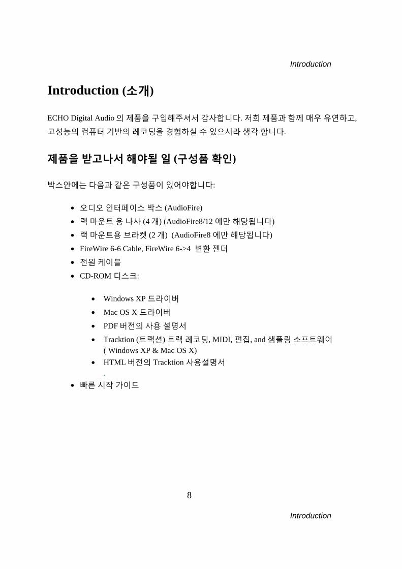
Introduction (소개) ECHO Digital Audio 의 제품을 구입해주셔서 감사합니다. 저희 제품과 함께 매우 유연하고,
고성능의 컴퓨터 기반의 레코딩을 경험하실 수 있으시라 생각 합니다.
제품을 받고나서 해야될 일 (구성품 확인) 박스안에는 다음과 같은 구성품이 있어야합니다:
• 오디오 인터페이스 박스 (AudioFire)
• 랙 마운트 용 나사 (4 개) (AudioFire8/12 에만 해당됩니다)
• 랙 마운트용 브라켓 (2 개) (AudioFire8 에만 해당됩니다)
• FireWire 6-6 Cable, FireWire 6->4 변환 젠더
• 전원 케이블
• CD-ROM 디스크: • Windows XP 드라이버
• Mac OS X 드라이버
• PDF 버전의 사용 설명서
• Tracktion (트랙션) 트랙 레코딩, MIDI, 편집, and 샘플링 소프트웨어 ( Windows XP & Mac OS X)
• HTML 버전의 Tracktion 사용설명서 .
• 빠른 시작 가이드
Introduction
9 Introduction
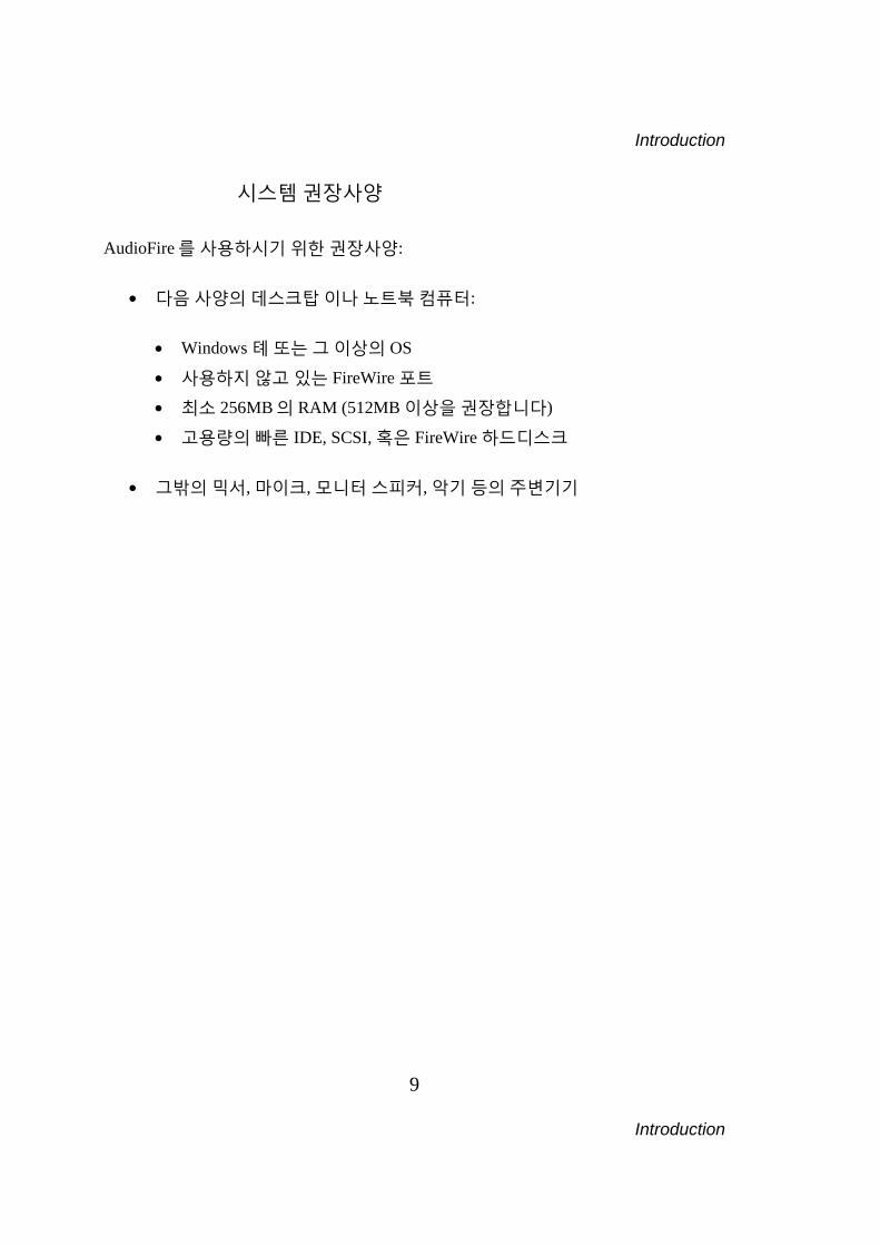
시스템 권장사양 AudioFire 를 사용하시기 위한 권장사양:
• 다음 사양의 데스크탑 이나 노트북 컴퓨터:
• Windows 톄 또는 그 이상의 OS
• 사용하지 않고 있는 FireWire 포트
• 최소 256MB 의 RAM (512MB 이상을 권장합니다)
• 고용량의 빠른 IDE, SCSI, 혹은 FireWire 하드디스크
• 그밖의 믹서, 마이크, 모니터 스피커, 악기 등의 주변기기
Installation
10 Installation
Installation (설치) 설치과정은 관리자 계정으로 로그인 하기, 시스템 드라이버 설치하기, 오디오
인터페이스를 FireWire 로 연결하기 그리고 트랙션 소프트웨어 설치로 구성되어 있습니다.
관리자 계정으로 로그인 하기 ECHO 제품을 설치하기 위해서는 관리자 예정으로 로그인해야 합니다. “Administrator”
계정으로 로그인 하거나 관리자와 동급의 능력을 가지고 있는 계정을 사용하셔야 됩니다.
그렇지 않을 경우, 제품을 설치할 수 없으며 설치시에 오류가 발생할 수 있습니다.
ECHO 웹사이트에서 최신버전 확인하기 www.echoaudio.com 에서 최신버전의 드라이버가 있는지 설치하기 전에 확인하시기
바랍니다. Downloads 의 AudioFire 섹션을 보시기 바랍니다. 만일 최신버전이 있을시에는
최신버전을 CDROM 의 드라이버 대신 사용합니다. 최신버전일 수록 높은 버전 넘버를
가지고 있습니다.
Installation
11 Installation
AudioFire 하드웨어와 소프트 웨어 설치 관리자 계정으로 로그인하신 후에 설치를 시작합니다. 1. 드라이버 설치시 반드시 AudioFire 인터페이스를 컴퓨터의 포트에 연결하기 전에
설치하셔야 합니다. CDROM 을 넣으시면 설치화면이 나오게 됩니다. (나오지 않을
경우 “내컴퓨터”의 CDROM 을 더블클릭합니다.) “Install Windows Drivers,” 를
선택하고 화면의 지시사항을 따릅니다. 홈페이지에서 최신버전을 찾으셨다면 그것을
실행하면 됩니다. 2. 드라이버 설치가 완료되면 AudioFire, 전원케이블, FireWire 케이블을 준비합니다.
제품을 랙에 단단하게 고정합니다. 랙을 사용하지 않으시면 제품을 안전한 곳에
놓습니다. 3. 전원케이블을 확실하게 제품과 콘센트에 꼽고 파워버튼을 눌러 전원을 켭니다. 4. FireWire cable 의 한쪽을 AudioFire 뒤의 FireWire 포트에 꼽습니다. 다른 한쪽은
컴퓨터의 FireWire 에 포트에 연결합니다. (만약 케이블이 컴퓨터의 포트와 맞지
않을경우엔, 아답터를 사용하여야 합니다.) 5. 윈도우가 “AudioFire”란 하드웨어를 자동적으로 찾고 드라이버를 설치하게 됩니다.
“소프트웨어를 자동으로 설치” 옵션을 선택하고 화면의 지시사항을 따라서
설치합니다. Note: 현재 오디오 인터페이스는 Microsoft 디지털 서명된 버전의 WDM 를 만들기가
사실상 불가능한 관계로 드라이버 설치시에 서명되지 않은 드라이버를 설치할 거냐고
묻는 부분니 나오면 무시하고 확인을 누르셔야 합니다. 6. 설치가 끝난 후 외부기기들을 AudioFire 에 연결해서 사용할 수 있습니다. 외부기기를
연결하는 데에 관한 자세한 정보는 “오디오 인터페이스에 연결하기” 부분을
참고해주세요.
Installation
12 Installation
7. 다음으로 AudioFire 콘솔을 실행합니다. 콘솔은 시작메뉴의 ECHO Digital and
AudioFire 메뉴에 있습니다. 콘솔을 처음 실행하게 되면, AudioFire 가 최신의 펌웨어를
가지고 있는 체크하게 됩니다. 만약 새버전이 존재하면 “Yes”를 눌러 펌웨어를
설치합니다. 펌웨어가 설치될 동안에는 절대로 AudioFire 를 끄거나 케이블의 연결을
끊지마시기 바랍니다! 펌웨어 업데이트가 완료되면 AudioFire 를 재시작(1394
케이블을 뺏다가 끼우거나 전원을 뺏다 켬)하여 사용하셔야 합니다.
Connecting to the Audio Interface
13 Connecting to the Audio Interface
오디오 인터페이스에 연결하기 AudioFire2, AudioFire4, AudioFire8 와 AudioFire12 오디오 인터페이스는 다양한
연결지원으로 뛰어난 유용성을 제공합니다. 최적의 성능을 위해서 알맞은 케이블 연결과
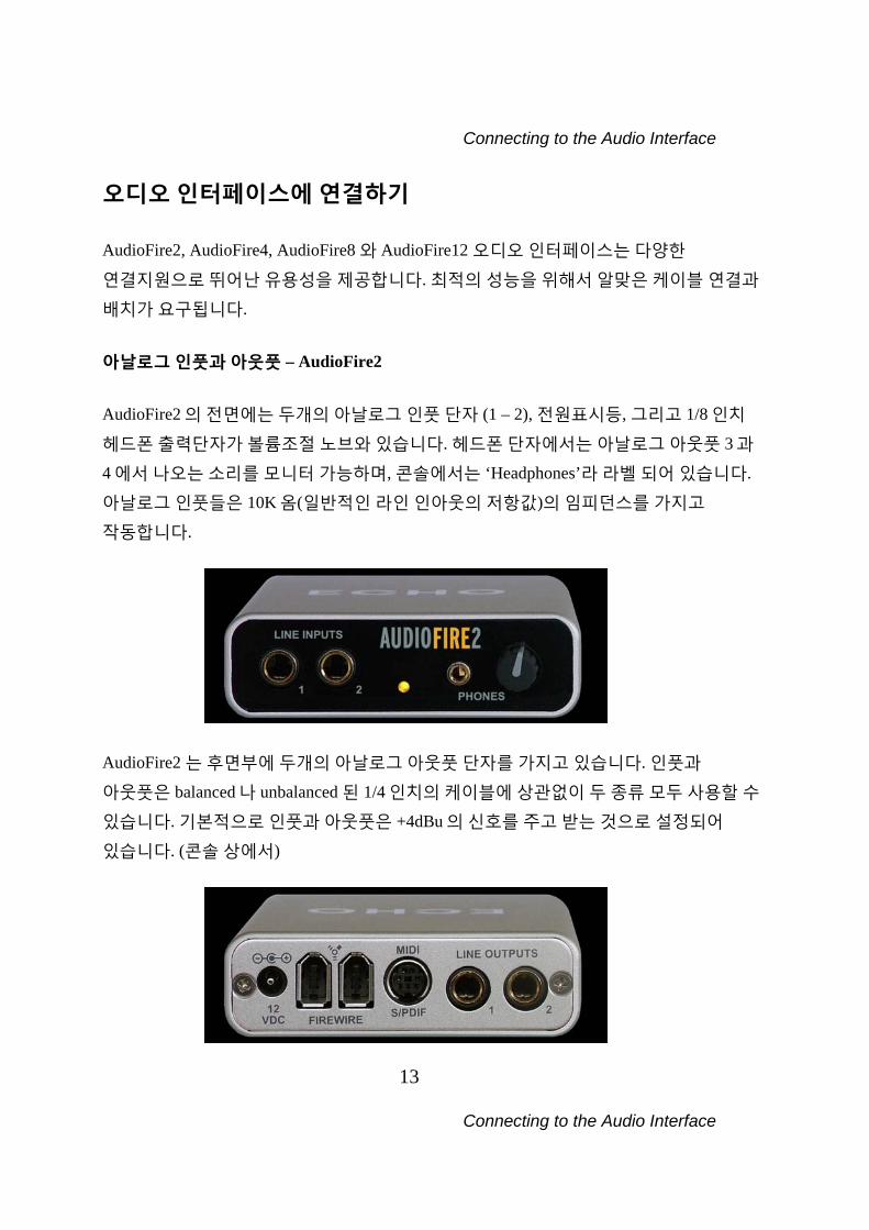
배치가 요구됩니다. 아날로그 인풋과 아웃풋 – AudioFire2
AudioFire2 의 전면에는 두개의 아날로그 인풋 단자 (1 – 2), 전원표시등, 그리고 1/8 인치
헤드폰 출력단자가 볼륨조절 노브와 있습니다. 헤드폰 단자에서는 아날로그 아웃풋 3 과
4 에서 나오는 소리를 모니터 가능하며, 콘솔에서는 ‘Headphones’라 라벨 되어 있습니다.
아날로그 인풋들은 10K 옴(일반적인 라인 인아웃의 저항값)의 임피던스를 가지고
작동합니다.
AudioFire2 는 후면부에 두개의 아날로그 아웃풋 단자를 가지고 있습니다. 인풋과
아웃풋은 balanced 나 unbalanced 된 1/4 인치의 케이블에 상관없이 두 종류 모두 사용할 수
있습니다. 기본적으로 인풋과 아웃풋은 +4dBu 의 신호를 주고 받는 것으로 설정되어
있습니다. (콘솔 상에서)
Connecting to the Audio Interface
14 Connecting to the Audio Interface
콘솔 소프트웨어에서 각가의 인풋과 아웃풋을 +4dBu 와 -10dBV 사이로 조절할 수
있습니다. (아래의 ‘콘솔’ 섹션 참고)
Connecting to the Audio Interface
15 Connecting to the Audio Interface
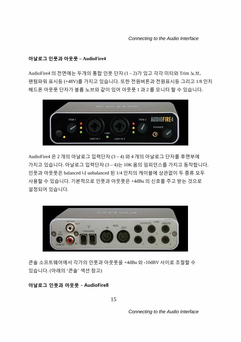
아날로그 인풋과 아웃풋 – AudioFire4
AudioFire4 의 전면에는 두개의 통합 인풋 단자 (1 – 2)가 있고 각각 미터와 Trim 노브,
팬텀파워 표시등 (+48V)를 가지고 있습니다. 또한 전원버튼과 전원표시등 그리고 1/8 인치
헤드폰 아웃풋 단자가 볼륨 노브와 같이 있어 아웃풋 1 과 2 를 모니터 할 수 있습니다.
AudioFire4 은 2 개의 아날로그 입력단자 (3 – 4) 와 4 개의 아날로그 단자를 후면부에
가지고 있습니다. 아날로그 입력단자 (3 – 4)는 10K 옴의 임피던스를 가지고 동작합니다.
인풋과 아웃풋은 balanced 나 unbalanced 된 1/4 인치의 케이블에 상관없이 두 종류 모두
사용할 수 있습니다. 기본적으로 인풋과 아웃풋은 +4dBu 의 신호를 주고 받는 것으로
설정되어 있습니다.
콘솔 소프트웨어에서 각가의 인풋과 아웃풋을 +4dBu 와 -10dBV 사이로 조절할 수
있습니다. (아래의 ‘콘솔’ 섹션 참고) 아날로그 인풋과 아웃풋 - AudioFire8
Connecting to the Audio Interface
16 Connecting to the Audio Interface
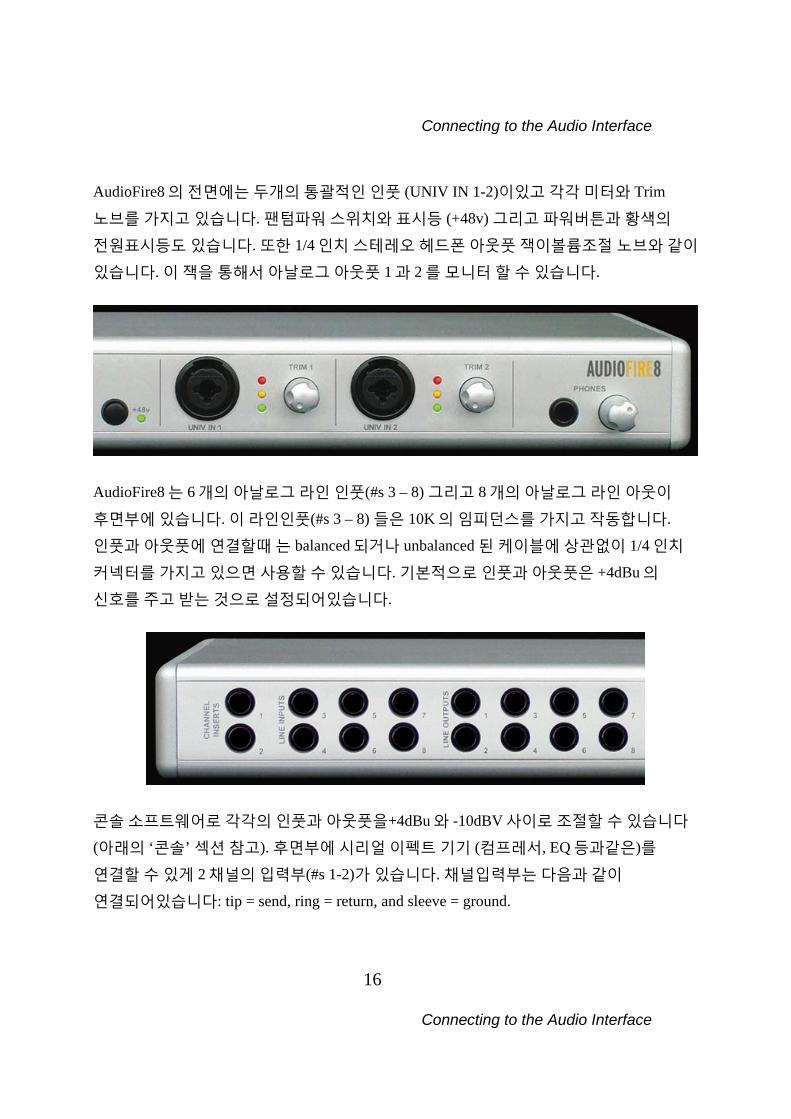
AudioFire8 의 전면에는 두개의 통괄적인 인풋 (UNIV IN 1-2)이있고 각각 미터와 Trim
노브를 가지고 있습니다. 팬텀파워 스위치와 표시등 (+48v) 그리고 파워버튼과 황색의
전원표시등도 있습니다. 또한 1/4 인치 스테레오 헤드폰 아웃풋 잭이볼륨조절 노브와 같이
있습니다. 이 잭을 통해서 아날로그 아웃풋 1 과 2 를 모니터 할 수 있습니다.
AudioFire8 는 6 개의 아날로그 라인 인풋(#s 3 – 8) 그리고 8 개의 아날로그 라인 아웃이
후면부에 있습니다. 이 라인인풋(#s 3 – 8) 들은 10K 의 임피던스를 가지고 작동합니다.
인풋과 아웃풋에 연결할때 는 balanced 되거나 unbalanced 된 케이블에 상관없이 1/4 인치
커넥터를 가지고 있으면 사용할 수 있습니다. 기본적으로 인풋과 아웃풋은 +4dBu 의
신호를 주고 받는 것으로 설정되어있습니다.
콘솔 소프트웨어로 각각의 인풋과 아웃풋을+4dBu 와 -10dBV 사이로 조절할 수 있습니다
(아래의 ‘콘솔’ 섹션 참고). 후면부에 시리얼 이펙트 기기 (컴프레서, EQ 등과같은)를
연결할 수 있게 2 채널의 입력부(#s 1-2)가 있습니다. 채널입력부는 다음과 같이
연결되어있습니다: tip = send, ring = return, and sleeve = ground.
Connecting to the Audio Interface
17 Connecting to the Audio Interface
유니버셜 인풋 – AudioFire4 와 AudioFire8 유니버셜 인풋은 1/4 인치와 XLR 커넥터로 balanced 나 unbalanced 신호를 받아들일 수
있습니다. AudioFire4,8 가 preamp 를 가지고 있으므로, 마이크나 기타를 인풋에 그냥
꼽기만 하면 사용가능합니다. 외장형 프리앰프나 direct box 또는 믹서가 필요치 않습니다! 마이크를 사용하기 위해서, 마이크의 XLR 케이블을 유니버셜 인풋에 꼽습니다. XLR
케이블이 유니버셜 인풋에 꼽힐때는 자동적으로 마이크 프리앰프가 가동되고 gain 노브
범위가 +10 에서 +59dB 로 변경됩니다. 각각의 마이크 프리앰프의 인풋 임피던스는
1.5K 옴입니다. 최소 gain 으로 설정되었을때 Full-scale 인풋은 9dBu 이 됩니다. AudioFire4,8 는 마이크가 필요로 하는 48v 의 팬텀파워를 지원합니다. 팬텀파워를
작동시키기 위해선, +48v 라 명칭된 버튼을 누릅니다.(바로 옆 LED 등이 켜지게 됩니다.)
그리고 팬텀파워가 모든 마이크 입력에 지원되게 됩니다.
Note: 1/4 인치 커넥터로 연결된 다른 장비나 기타에는 팬텀파워가 적용되지
않습니다. 기타나 라인 입력 레벨 신호를 녹음하려면, 1/4 인치 커넥터로 인풋에 기기를 연결합니다.
1/4 인치 케이블이 인풋에 꼽힐때는 자동적으로 기타/라인 프리앰프가 자동적으로
가동되고 gain 노브범위가 0 에서 +45 로 변경됩니다. 기타/라인 프리앰프는 기타와 라인
입력 신호를 지원합니다. 각각의 기타/라인 프리앰프의 임피던스는 102K 옴입니다. 최소
gain 으로 설정되었을때 Full-scale 인풋은 18dBu 입니다. 유니버셜 인풋의 레벨을 조절하려면, 노브를 돌려 그에 해당되는 레벨미터를 보며
조절합니다. 인풋신호가 -6.5dBFS 보다 높으면 빨간불이 점등됩니다. 노란불은 -
12.5dBFS 보다 클 때, 녹색불은 -36.5dBFS 보다 높을 때 점등됩니다. 최적의 음질을 위해서, 노브를 조절해서 가장 큰 녹음 신호가 노란불을 점등하게끔합니다.
빨간불을 점등하게 하지 않습니다. 빨간불이 더더욱 빛날시에는 오디오가 잘리고 있다는
것을 표현하는 것입니다! 신호 레벨이 0dBFS 를 넘을시에는 신호는 “잘리게” 되고
Connecting to the Audio Interface
18 Connecting to the Audio Interface
“팝”이나 “틱”을 녹음된 결과물에서 듣게 됩니다. 클리핑은 상당히 안좋은 것이고, 반드시
피해야되는 것입니다! 충분한 공간이 있기때문에 약간 조심성이 있어도 됩니다. 그리고
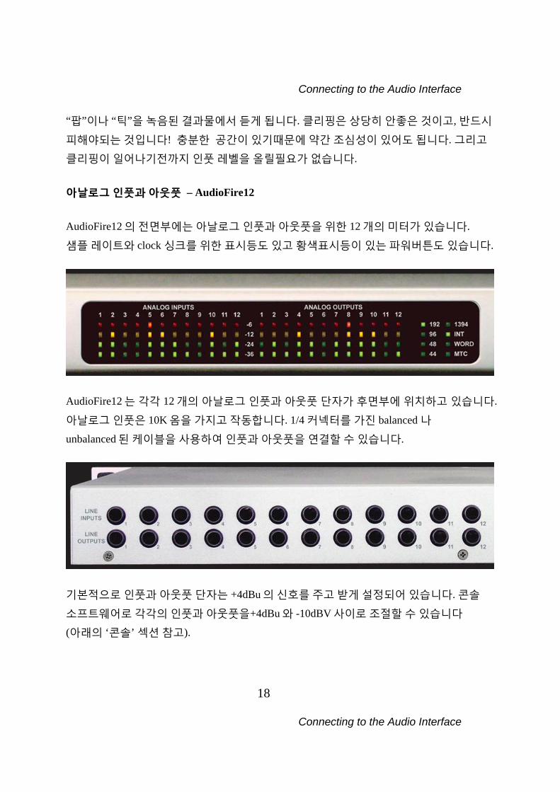
클리핑이 일어나기전까지 인풋 레벨을 올릴필요가 없습니다. 아날로그 인풋과 아웃풋 – AudioFire12 AudioFire12 의 전면부에는 아날로그 인풋과 아웃풋을 위한 12 개의 미터가 있습니다.
샘플 레이트와 clock 싱크를 위한 표시등도 있고 황색표시등이 있는 파워버튼도 있습니다.
AudioFire12 는 각각 12 개의 아날로그 인풋과 아웃풋 단자가 후면부에 위치하고 있습니다.
아날로그 인풋은 10K 옴을 가지고 작동합니다. 1/4 커넥터를 가진 balanced 나
unbalanced 된 케이블을 사용하여 인풋과 아웃풋을 연결할 수 있습니다.
기본적으로 인풋과 아웃풋 단자는 +4dBu 의 신호를 주고 받게 설정되어 있습니다. 콘솔
소프트웨어로 각각의 인풋과 아웃풋을+4dBu 와 -10dBV 사이로 조절할 수 있습니다
(아래의 ‘콘솔’ 섹션 참고).
Connecting to the Audio Interface
19 Connecting to the Audio Interface
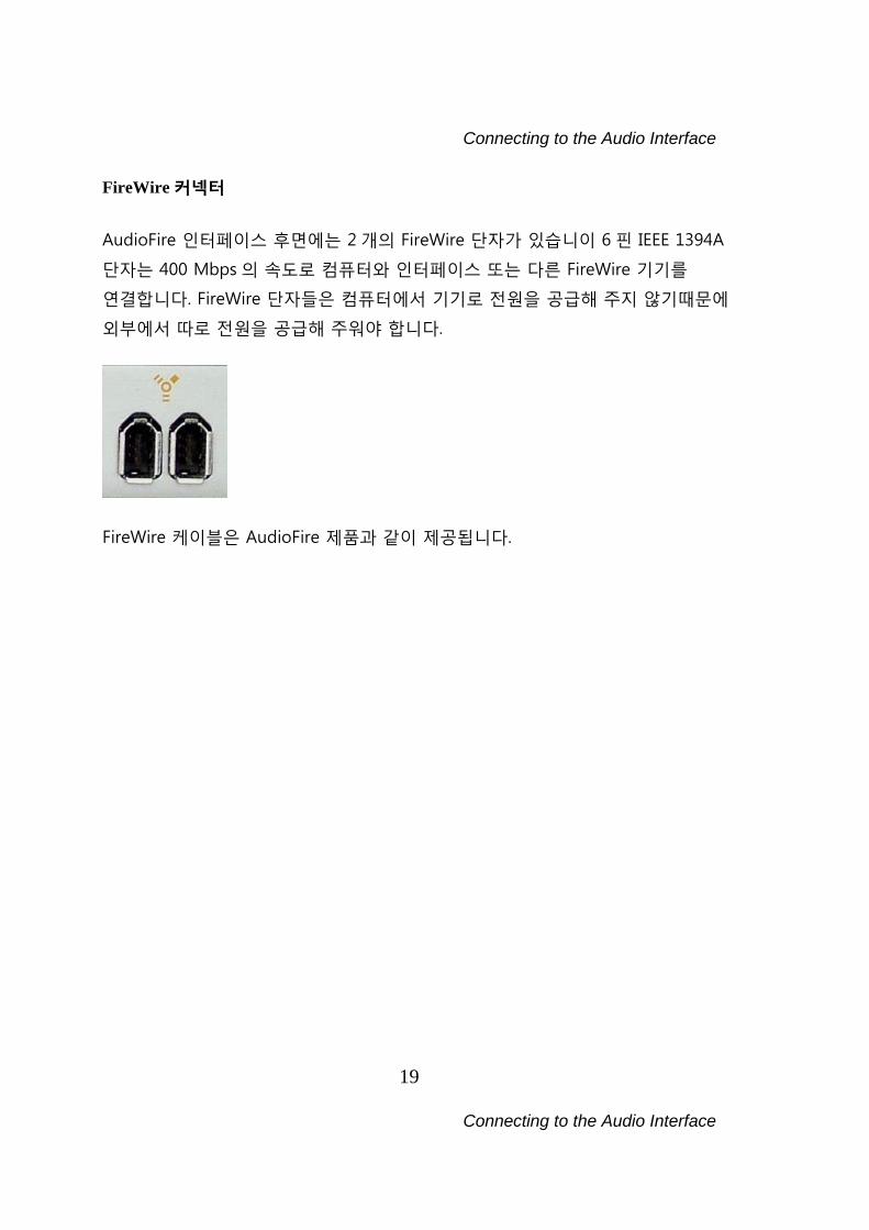
FireWire 커넥터 AudioFire 인터페이스 후면에는 2 개의 FireWire 단자가 있습니이 6 핀 IEEE 1394A
단자는 400 Mbps 의 속도로 컴퓨터와 인터페이스 또는 다른 FireWire 기기를
연결합니다. FireWire 단자들은 컴퓨터에서 기기로 전원을 공급해 주지 않기때문에
외부에서 따로 전원을 공급해 주워야 합니다.
FireWire 케이블은 AudioFire 제품과 같이 제공됩니다.
Connecting to the Audio Interface
20 Connecting to the Audio Interface
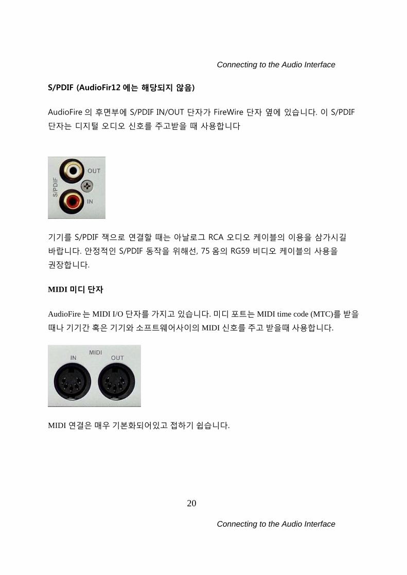
S/PDIF (AudioFir12 에는 해당되지 않음)
AudioFire 의 후면부에 S/PDIF IN/OUT 단자가 FireWire 단자 옆에 있습니다. 이 S/PDIF
단자는 디지털 오디오 신호를 주고받을 때 사용합니다
기기를 S/PDIF 잭으로 연결할 때는 아날로그 RCA 오디오 케이블의 이용을 삼가시길
바랍니다. 안정적인 S/PDIF 동작을 위해선, 75 옴의 RG59 비디오 케이블의 사용을
권장합니다.
MIDI 미디 단자 AudioFire 는 MIDI I/O 단자를 가지고 있습니다. 미디 포트는 MIDI time code (MTC)를 받을
때나 기기간 혹은 기기와 소프트웨어사이의 MIDI 신호를 주고 받을때 사용합니다.
MIDI 연결은 매우 기본화되어있고 접하기 쉽습니다.
Connecting to the Audio Interface
21 Connecting to the Audio Interface
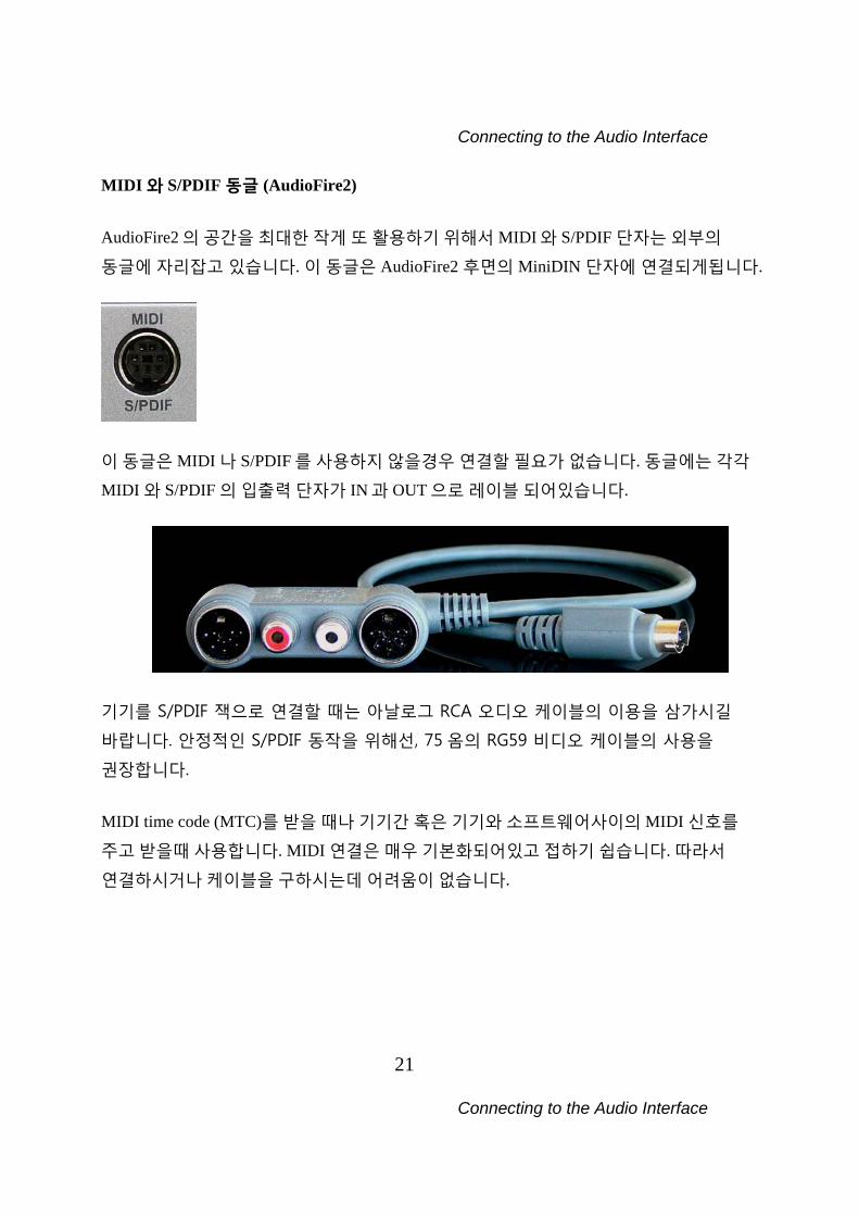
MIDI 와 S/PDIF 동글 (AudioFire2) AudioFire2 의 공간을 최대한 작게 또 활용하기 위해서 MIDI 와 S/PDIF 단자는 외부의
동글에 자리잡고 있습니다. 이 동글은 AudioFire2 후면의 MiniDIN 단자에 연결되게됩니다.
이 동글은 MIDI 나 S/PDIF 를 사용하지 않을경우 연결할 필요가 없습니다. 동글에는 각각
MIDI 와 S/PDIF 의 입출력 단자가 IN 과 OUT 으로 레이블 되어있습니다.
기기를 S/PDIF 잭으로 연결할 때는 아날로그 RCA 오디오 케이블의 이용을 삼가시길
바랍니다. 안정적인 S/PDIF 동작을 위해선, 75 옴의 RG59 비디오 케이블의 사용을
권장합니다.
MIDI time code (MTC)를 받을 때나 기기간 혹은 기기와 소프트웨어사이의 MIDI 신호를
주고 받을때 사용합니다. MIDI 연결은 매우 기본화되어있고 접하기 쉽습니다. 따라서
연결하시거나 케이블을 구하시는데 어려움이 없습니다.
Connecting to the Audio Interface
22 Connecting to the Audio Interface
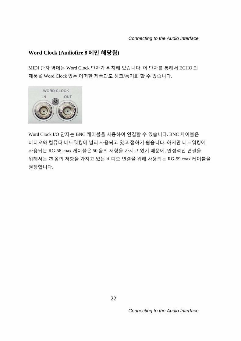
Word Clock (Audiofire 8 에만 해당됨) MIDI 단자 옆에는 Word Clock 단자가 위치해 있습니다. 이 단자를 통해서 ECHO 의
제품을 Word Clock 있는 어떠한 제품과도 싱크/동기화 할 수 있습니다.
Word Clock I/O 단자는 BNC 케이블을 사용하여 연결할 수 있습니다. BNC 케이블은
비디오와 컴퓨터 네트워킹에 널리 사용되고 있고 접하기 쉽습니다. 하지만 네트워킹에
사용되는 RG-58 coax 케이블은 50 옴의 저항을 가지고 있기 때문에, 안정적인 연결을
위해서는 75 옴의 저항을 가지고 있는 비디오 연결을 위해 사용되는 RG-59 coax 케이블을
권장합니다.
Installing Tracktion
23 Installing Tracktion
Tracktion (트랙션) 설치하기 AudioFire 에는 오디오 멀티채널 녹음, MIDI, 편집, 그리고 샘플링 소프트웨어가
기본적으로 제공됩니다. Tracktion 은 설치하지 않아도 AudioFire 를 사용하는데 아무런 지장을 주지 않습니다. CDROM 으로부터 Tracktion 설치하기 소프트웨어를 설치하려면:
1. AudioFire CD-ROM 을 PC 에 삽입합니다
2. 메인 설치화면이 자동적으로 나오게 됩니다. 만약 나오지 않을시에는 “내 컴퓨터”로
가서 CD-ROM 아이콘을 더블클릭합니다.
3. 메인 설치화면에서 “Install Tracktion”을 선택하고 나오는 지시사항을 따릅니다.
Tracktion 셋업이 필요한 파일들을 하드드라이브에 설치합니다. 시작버튼을 누를시에
나오는 프로그램리스트에 “Tracktion”이란 프로그램 그룹또한 만들게 됩니다. Tracktion 에서 “Help”버튼을 누르면 HTML 로 쓰여진 “사용설명서”를 보시게 됩니다.
그리하여 어려움없이 프로그램을 사용할 수 있습니다. “사용설명서”는 “Tracktion”
프로그램 그룹안에서 열어보실 수도 있습니다. Tracktion 인증받기 인증을 받기전까지 Tracktion 은 데모모드로 작동합니다. AudioFire 에 부착되어있는
인증번호로 같이 기재된 웹사이트에 가서 인증을 받습니다. 웹사이트 방문하셔서
가이드에 따라주시기 바랍니다.
Installing Tracktion
24 Installing Tracktion
NOTE: 인증번호를 잃어버리지 마세요!!!! ECHO 는 분실된 번호에 대해서 어떠한 책임도
지지않습니다.
Console Software
25
Console Software
Tracktion 실행 및 인/아웃풋 지정하기 이제 프로그램을 실행해서 몇가지 옵션을 지정합니다:
1. “시작”을 누르거나 바탕화면에 있는 Tracktion 프로그램을 찾습니다.
2. 프로그램 메뉴에 있는 프로그램을 선택하여 (혹은 아이콘을 더블클릭해서)
프로그램을 실행합니다. Tracktion 프로그램을 처음 실행시에, Projects 페이지로 이동하게 됩니다. 마우스 커서를
스크린의 개체로 이동시에 Tracktion 이 팝업으로 인터페이스에 대해 설명해 줍니다. 개체를 클릭하여 선택하게되면 정보창이 화면 아래 중앙에 표시되고, 이 정보창에는
세부사항, 컨트롤, 그리고 세팅등이 표시되게 됩니다. 개체를 클릭하거나 커서이동시 뜨는
팝업창으로 인해 상당히 많은 것을 알 수 있습니다. 빠른 시작 설명과 자세한 설명서는 프로그램상에서 왼쪽밑의 “Help!” 버튼을 누르고 “sow
the Tracktion help pages…”나 F12 키를 누르면 볼 수 있습니다. AudioFire 제품과 가장
첫번째로 하고픈 것은 아마도 재생과 녹음 셋업일 것 입니다.
Audio Settings (오디오 설정) 1. 화면 위 쪽의 “Settings” 탭으로 이동합니다.
2. 왼쪽의 “Audio Devices”를 선택합니다.
3. “Wave device:”라고 보일때 메뉴를 끌어내려 “ASIO AudioFire”를 선택합니다.
4. 이제 AudioFire 제품의 사용가능한 오디오 기기들이 보일 것입니다. 사용하고자 하는
인풋과 아웃풋을 정해서 적색 X 를 누르고 녹색 체크마크로 변할 때까지 기다립니다.
Console Software
26
Console Software
5. AudioFire 의 아웃풋중에 하나가 “default wave output”인지 확인하고 그 아웃풋이
스피커나 헤드폰에 연결합니다. Tracktion 의 오른쪽에 “Settings – Audio devices”에서
설정을 체크할 수 있습니다.
6. 이제 음악을 재생할 수 있습니다. 화면 위쪽의 “Projects” 탭으로 이동해서
Tracktion 에서 제공하는 샘플 projects 를 선택합니다.
7. 오른쪽의 큰지역에 project 에 사용된 모든 파일들을 보게됩니다. Project 와 같은
이름의 파일을 더블클릭하여 project 를 엽니다.
8. 화면의 오른쪽 밑 play 버튼을 눌러 재생합니다. 그러면 AudioFire 제품으로 샘플
project 가 재생되는 것을 듣게됩니다.
9. 음악을 즐기세요!! F12 를 누르면 “사용설명서”가 나옵니다 보다 자세한 설명을 보실 수 있습니다. Tracktion
사용자 포럼에서 보다 많은 정보를 얻으실 수도 있습니다: http://www.mackie.com/products/tracktion/tracktion.html NOTE: Tracktion 버전 1 은 샘플 레이트 96kHz 이상을 지원하지 않습니다.
이것으로 AudioFire 의 설치가 끝나게 됩니다.
Console Software
27
Console Software
Console (콘솔)
“가상 컨트롤” 응용프로그램이라 불리는 콘솔이 드라이버와 같이 설치가 됩니다.
콘솔은 ECHO 제품의 오디오 I/O 와 clocking 기능을 제어할 수 있게 하며 이 제어들은
한곳에 모아 쉽게 할 수 있게 합니다. 아웃풋 레벨, 싱크/동기화 클럭 선택, 그리고 인풋
모니터링을 제어할 수 있습니다. AudioFire8 의 콘솔을 기준으로 설명하겠지만
AudioFire2/4/8 의 그것도 크게 다르지 않습니다.
콘솔 실행하기 설치가 끝난 후에 “시작”메뉴에서 콘솔을 찾으실 수 있습니다. 콘솔 프로그램을
실행하려면, “AudioFire”의 “ECHO Digital Audio”그룹으로 가서 “Show Console”을
클릭합니다.
자동 플래쉬 업데이트 콘솔이 실행될때, AudioFire 가 사용하고 있는 펌웨어를 체크하게됩니다. 만약에 현재
AudioFire 가 오래된 펌웨어를 가지고 있을시에 펌웨어를 업데이트 할 것이냐는 확인창이
나오게 됩니다. “Yes”버튼을 클릭하시면, 가장최근의 펌웨어로 업데이트 되고,
업데이트가 끝난후에는 AudioFire 를 리부팅해주셔야됩니다.
Console Software
28
Console Software
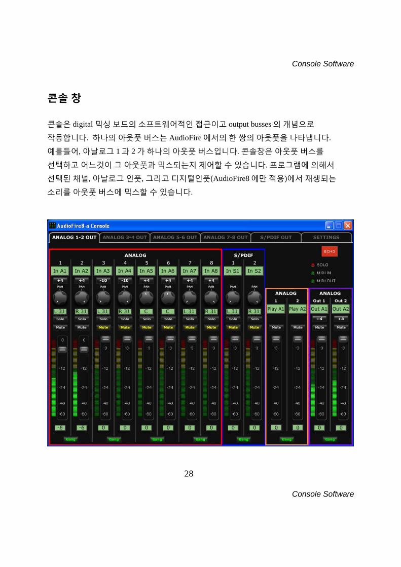
콘솔 창 콘솔은 digital 믹싱 보드의 소프트웨어적인 접근이고 output busses 의 개념으로
작동합니다. 하나의 아웃풋 버스는 AudioFire 에서의 한 쌍의 아웃풋을 나타냅니다.
예를들어, 아날로그 1 과 2 가 하나의 아웃풋 버스입니다. 콘솔창은 아웃풋 버스를
선택하고 어느것이 그 아웃풋과 믹스되는지 제어할 수 있습니다. 프로그램에 의해서
선택된 채널, 아날로그 인풋, 그리고 디지털인풋(AudioFire8 에만 적용)에서 재생되는
소리를 아웃풋 버스에 믹스할 수 있습니다.
Console Software
29
Console Software
AudioFire8 콘솔창: 아날로그 아웃 1-2 탭이 선택
Console Software
30
Console Software
버스 채널 선택하기 콘솔창에서 탭을 선택함으로써 아웃풋 버스를 선택할 수 있습니다. 위는
AudioFire8 에서의 콘솔창을 예로 보여주고 있습니다. 5 개의 다른 아웃풋 버스들이
보여지고 있습니다: 4 개의 아날로그 버스들과 1 개의 디지털 버스. 각각의 아웃풋 버스는
개별의 탭을 가지고 있으며, “ANALOG” 나 “DIGITAL” 그리고 채널 넘버를 가지고
있습니다. 탭을 선택하면 선택된 탭은 흰색이 되고 나머지 탭들은 회색이 됩니다. 위에는
현재 “ANALOG OUT 1-2”이 선택되어 있습니다. 아웃풋 탭을 선택하는 것으로 현재
보여지는 세팅이 선택되게 됩니다. AudioFire 의 아날로그 아웃풋의 1 과 2 의 모든
파라미터 (볼륨, 팬, 음소거)들만에 화면의 표시된 설정이 적용됩니다. 다른 아웃풋의
파라미터를 변경하기 위해선 그에 해당되는 탭을 먼저 선택해서 변경해야 합니다.
F1 부터 F5 의 키를 눌러서 탭을 변경할 수 있습니다. AudioFire12 는 S/PDIF 단자가
없기때문에 디지털 아웃풋 버스가 없습니다. 다만 6 개의 아날로그 아웃풋 버스 탭이
존재합니다. NOTE: AudioFire2 에서의 아날로그 아웃풋 3 과 4 는 콘솔에서 “Headphones”이라
명명되어있습니다.
Console Software
31
Console Software
마스터 아웃풋 버스 컨트롤 마스터 아웃풋 버스 컨트롤은 콘솔창의 가장 오른쪽에 위치하고 있습니다. 위의 그림에서
보라색의 아웃라인으로 표시되어 있습니다. 맨위의 타이틀에서“ANALOG”, “OUT
1”,그리고 “OUT 2.”라고 표시되어있듯이 현재 아날로그 아웃풋 1 과 2 에 믹스되는 모든
것을 제어하고 있는 것입니다. 이 채널들은 현재 선택된 아웃풋 버스탭의 선택된 버스의
상태를 표시합니다. 타이틀 밑에는 변경가능한 두개의 녹색 라벨이 존재합니다. 그 밑에는 음소거 버튼,
레벨미터, 그리고 페이더가 있습니다. 음소거 버튼과 페이더는 현재 버스에 믹스되고있는
모든것에 적용됩니다. 그러므로, 페이더를 내리게 되면 인풋 모니터와 재생을 줄이게
됩니다. 페이더 밑의 녹색의 박스에 숫자를 직접 입력하여 페이더 값을 조절할 수
있습니다. 레벨미터는 현재 선택된 아웃풋들에 전달되어지는 신호의 값을 나타냅니다. 이
레벨미터는 하나의 “작은 미터”가 되어 상응되는 아웃풋 버스탭에 항상 보여지게 됩니다. Gang 버튼은 gang 모드를 활성화 시킵니다. gang 모드에서는 음소거 버튼이 양쪽 채널에
동시에 적용됩니다. 예로 한채널에서의 음소거버튼의 작동은 다른 채널에도 음소거가
적용되게 합니다. 또한 페이더도 하나로 묶어서 상대적인 위치도 유지하게 됩니다.
Shift 키를 누름으로써 일시적인 gang 모드에서 벗어나게 할 수 있습니다. Gang 버튼을
다시 눌러 gang 모드에서 빠져나가지 않고 gang 모드밖의 설정을 바꿀수도 있으며,
일반모드에서 일시적인 gang 모드도 반대로 가능하게 됩니다.
아날로그 인풋 아날로그 인풋 컨트롤은 콘솔창 왼쪽에 “ANALOG” 그리고 “IN 1”부터 “IN 8” 라고
타이틀이 붙어서 존재합니다. 위의 사진에서 적색 아웃라인으로 표시가 되어있습니다.
Console Software
32
Console Software
하나의 조각 또는 인풋 채널은 AudioFire8 의 하나의 인풋에 해당되게 됩니다. 인풋 레벨
미터는 항상 보여지게 되어 있고, 어떠한 아웃풋 버스를 선택하느냐에 따라서 그에
해당되는 인풋 모니터 값(팬, 솔로, 음소거, 페이더, gang)들이 바뀌어 표시됩니다. 인풋 모니터 제어는 약간 복잡할 수 있습니다. 기본적으로 각각의 아웃풋버스는 그에 따른
다른 인풋 모니터 제어가 있습니다. 그러나 하나의 세트만 보여지고 변경이 가능합니다.
위의 사진의 예를 들자면, “ANALOG OUT 1-2" 아웃풋 버스에 상응하는 인풋 모니터
제어값들만 보이게 되고 변경을 가능한 것입니다. (즉, 선택된 버스에 해당하는 모니터
값만 변경가능합니다.) 다른 인풋 모니터 세트와 값을 변경코자 하면, 다른 아웃풋 버스를
선택합니다. 어느 아웃풋 버스를 선택하던간에 레벨 미터는 변하지 않습니다. 인풋에 입력받는 신호의
크기를 나타내기 때문입니다. 사진에서 보이듯이 ANALOG OUT 1-2 의 레벨미터가
인풋의 미터보다 작습니다. ANALOG IN 1-2 의 페이더가 -19 로 설정되어있기때문에
아웃풋의 레벨은 인풋의 입력되는 신호보다 -19 만큼 적게 받기 때문입니다.
만약 ANALOG OUT 3-4 탭이 선택되어진다면 아래의 사진과 같이 표시되어집니다.
Console Software
33
Console Software
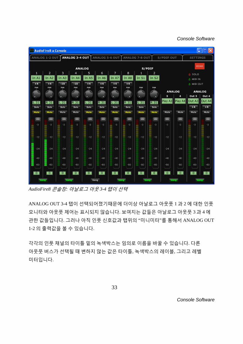
AudioFire8 콘솔창: 아날로그 아웃 3-4 탭이 선택 ANALOG OUT 3-4 탭이 선택되어졌기때문에 더이상 아날로그 아웃풋 1 과 2 에 대한 인풋
모니터와 아웃풋 제어는 표시되지 않습니다. 보여지는 값들은 아날로그 아웃풋 3 과 4 에
관한 값들입니다. 그러나 아직 인풋 신호값과 탭위의 “미니미터”를 통해서 ANALOG OUT
1-2 의 출력값을 볼 수 있습니다. 각각의 인풋 채널의 타이틀 밑의 녹색박스는 임의로 이름을 바꿀 수 있습니다. 다른
아웃풋 버스가 선택될 때 변하지 않는 값은 타이틀, 녹색박스의 레이블, 그리고 레벨
미터입니다.
Console Software
34
Console Software
인풋 채널 조각을 따라내려가면, 인풋 모니터 팬 노브가 먼저 나옵니다. 이 노브를
이용해서 선택된 아웃풋 버스에 어떻게 인풋이 모니터 되는지 변경할 수 있습니다. 팬
노브를 더블클릭하게되면 정중앙의 위치로 오게 됩니다. 각각의 노브 밑에는 선택이
불가능한 녹색박스가 있습니다. 이 박스는 현재의 팬 노브의 값이 표시됩니다. 팬 노브를
조절하는 것은 녹음에 전혀 적용되지 않습니다. 그저 아웃풋에 어떻게 인풋 신호가
가는지만을 조절하게 됩니다. 팬 노브 밑에는 솔로와 음소거 버튼이 있습니다. 솔로버튼을 적용시키면 선택된 아웃풋
버스는 솔로가 적용된 인풋만 모니터 하게 됩니다. 음소거버튼을 적용시키면 반대로
적용된 인풋이 모니터 되지 않게 합니다. 이 버튼들 또한 녹음에는 전혀 적용되지
않습니다. 그 밑에는 인풋 모니터 레벨을 조절하게끔 되어있는 모니터 페이더가 있습니다.
이 또한 녹음에는 적용되지 않습니다. 그 밑의 녹색박스를 선택하여 페이더값을 임의로
집어넣을 수도 있습니다. 페이더 밑에는 아웃풋 버스 컨트롤과 같이 gang 버튼이
자리잡고있으며 기능도 같은 역할을 하게 됩니다.
디지털 인풋 (AudioFire8 에만 해당) 디지털 인풋 컨트롤은 아날로그 인풋 컨트롤 바로 오른쪽에 자리잡고 있으며 “DIGITAL”,
“IN 1”, 그리고 “IN 2”의 타이틀을 가지고 있습니다. 위의 사진에 청색의 아웃라인으로
표시가 되어있습니다. 동작법은 아날로그 인풋과 동일합니다.
재생 컨트롤 재생 컨트롤은 마스터 아웃풋 컨트롤 바로 왼쪽에 자리잡고 있으며, 타이틀은 비슷하지만
“OUT” 대신에 “PLAY”가 있습니다. 위의 사진에 주홍색의 아웃라인으로 표시가
되어있습니다. 현재 선택된 아웃풋 버스에 의해 출력되어지는 오디오의 레벨에 값을
바꿉니다. 이 컨트롤들은 인풋 모니터 제어와 팬노브와 솔로버튼 그리고 레벨 미터가
없다는 것 빼고는 같게 동작합니다.
Console Software
35
Console Software
재생 볼륨 조절하기 아웃풋 볼륨조절은 디지털적으로 조절됩니다. 볼륨 페이더를 0dB 밑으로 조절하면,
사용가능한 bit 을 줄기게됩니다. 그리하여 시스템의 잠재적인 다이나믹 범위를 줄기게
됩니다. 그렇기 때문에 아웃풋 페이더 (재생과 아웃풋 버스)는 0dB 로 고정하고 조절은
외부의 믹서로 조절하길 권장합니다. 재생 볼륨 조절이 0dB 되고 인풋 신호가 클리핑이
일어나기 바로전 최고치에 도달하게되면 24-bit 의 넓은 다이나믹 레인지를 경험할 수
있습니다.
Nominal Levels (노미널 레벨) 콘솔안에서 “+4” 나 “-10”라고 이름붙여진 버튼들은 노미널 레벨 버튼입니다. 이 버튼들은
아날로그 인풋과 아웃풋의 노미널레벨(일반 규격값)을 변경할 수 있게 합니다.
기본적으로 레벨은 +4dBu 의 신호를 받게 설정되어 있습니다. 각각의 아날로그 인풋과
아웃풋을 +4dBu (프로페셔널 - balanced) 과 –10dBV (일반소비자 - unbalanced)의 값으로
선택할 수 있습니다. 이 설정으로 인해서 프로나 일반적인 기기를 각각의 인풋에 맞게
설정하여 연결할 수 있습니다.
Settings Tab (세팅 탭) 세팅탭을 클릭하면 다음과 화면을 보시게 됩니다.
Console Software
36
Console Software
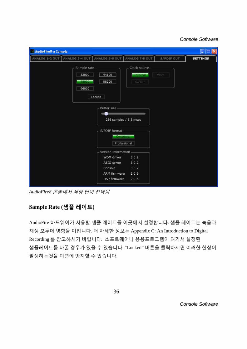
AudioFire8 콘솔에서 세팅 탭이 선택됨
Sample Rate (샘플 레이트) AudioFire 하드웨어가 사용할 샘플 레이트를 이곳에서 설정합니다. 샘플 레이트는 녹음과
재생 모두에 영향을 미칩니다. 더 자세한 정보는 Appendix C: An Introduction to Digital
Recording 를 참고하시기 바랍니다. 소프트웨어나 응용프로그램이 여기서 설정된
샘플레이트를 바꿀 경우가 있을 수 있습니다. “Locked” 버튼을 클릭하시면 이러한 현상이
발생하는것을 미연에 방지할 수 있습니다.
Console Software
37
Console Software
Clock Source (클럭 소스) “Clock” 에서는 클럭 레이트와 인풋 클럭소스를 선택할 수 있습니다. 클럭레이트, 내지는
샘플레이트는 녹음과 재생에 영향을 미칩니다. 더 많은 정보는 Appendix C:An Introduction
to Digital Recording 를 참고해 주시기 바랍니다. 인풋 클럭 설정은 AudioFire 가 다른 기기와 싱크/동기화 할때 사용됩니다. 인풋 클럭이
감지되었을때 버튼옆의 표시등이 녹색으로 점등되어집니다. 감지된 인풋 클럭들로만
선택이 가능합니다. 더 많은 정보는 “Synchronizing Multiple Devices” 를 참고해 주시기
바랍니다. Buffer Size Settings (버퍼 사이즈 설정) 이 슬라이더를 조절함으로써 오디오 소프트웨어가 AudioFire 와 같이 작업할때 사용하는
버퍼사이즈를 조절합니다. 샘플의 관점에서 레이턴시를 조절하게 됩니다. 성능과
안정성을 고려하여 가장 최적의 값을 선택하시길 바랍니다. Tracktion 을 제외한 거의 모든
프로페셔널한 오디오 프로그램은 이 세팅을 바탕으로 작동하게 됩니다. 그러나
소프트웨어가 이 세팅을 반드시 사용하게끔 하기위해서는 “Lock”의 체크박스에 체크를
하시기 바랍니다. 곧 드라이버 업데이트를 통해서 GSIF2 인풋과 낮은 레이턴시를
제공하는 커널레벨의 MIDI 인풋을 포함하고 있는 GigaStudio 3 에 대한 지원을
추가했으며 사용가능합니다.
S/PDIF 포맷 AudioFire2,4,8 는“professional” 이나 “consumer.”의 두가지 포맷중의 하나로 디지털 신호를
출력할 수 있습니다. 두개의 포맷의 가장큰 차이점은 SCMS 복사방지 bit 의
존재유무입니다.이 복사방지 bit 은 “consumer” 포맷에 포함되어 다른 유저가 복사/복제를
방지하게끔 합니다.
Console Software
38
Console Software
S/PDIF 출력은 기본적으로 Consumer 포맷으로 설정되어 있습니다. 녹음기기에 맞는
포맷이 선택되지 않으면 신호가 감지되지 않습니다.만일 하나의 포맷이 감지되지
않을시에는 다른 포맷을 선택하시기 바랍니다.
Note: ECHO 의 기기들은 어떠한 포맷이 선택되냐에 상관없이 SCMS bit 을 보내지
않습니다.
Version Information (버전 정보) 이 부분은 AudioFire 와 연관된 모든 부분의 버전 정보를 표시합니다. 이 정보는 후에
suppor 를 받으실 때 중요합니다.
콘솔 설정과 독립형 모드 (Stand-Alone) 콘솔이 닫히게 될때, 설정된 모든 콘솔 믹서값이 AudioFire 의 플래쉬 메모리에 저장되게
됩니다. 그리하여, AudioFire 가 리붓된 후나 다른 컴퓨터에서 사용할 때도 같은 세팅을
계속 유지, 사용할 수 있습니다. AudioFire 가 구동하기 위해서는 꼭 컴퓨터에 연결되어야 되는것이 아닙니다. 이것이
독립형(stand-alone) 모드입니다. 믹서세팅을 세팅에서 조절하시고 닫는것으로
AudioFire 가 독립적으로 컴퓨터 없이 자체내부의 믹서로 동작하게 됩니다. 독립형 모드에서는 AudioFire 가 48kHz 의 샘플레이트를 가지고 작동하게 됩니다.
Console Software
39
Console Software
외부 기기와의 동기화 (싱크) AudioFire 는 다른 기기들과 같이 작동하게 설계되었습니다. 다른 기기와 같이 사용하시게
될시에 다음을 명시하시기 바랍니다: 컴퓨터 외부의 기기와 AudioFire 를 같이 사용할 수 있습니다. 하지만 원활하고 정확한
동기화를 위해서 다른 외부기기가 반드시 AudioFire 와 호환되는 동기화 모드를
지원해야합니다. 그러한 동기화 모드가 없으면, 각 기기는 화합하지못하고 독립적으로
작동하게 됩니다. 음악적 응용프로그램에는 괜찮을 수 있으나, 정확한 샘플이나 신호가
관여하는 동기화에는 적절치 못합니다. 다양한 동기화 종류를 간략히 서술하였습니다. Word Clock – Word Clock 단자는 AudioFire8 과 AudioFire12 의 후면부에서 찾으실 수
있습니다. AudioFire 가 “Internal”로 설정되어 있을때에, 동기화 클럭은 AudioFire 의
샘플레이트에 따라 동기화 됩니다. 간단히 샘플레이트에 따라 움직이는 일종의
메트로놈(박절기)라 생각하시면 됩니다. 이 방법은 디지털 오디오 동기화에서 가장
보편화된 방법중의 하나입니다. AudioFire 는 Word Clock BNC 단자에서 계속하여 Word
Clock 신호를 전송하게 됩니다. Word Clock 을 어떠한 샘플레이트로도 만들 수 있지만,
AudioFire 는 마스터 기기의 Word Clock 이 30kHz 와 100kHz (AudioFire12 의 경우 200kHz)
사이로 설정된 경우에만 동기화가 가능합니다. 그렇지 않을 경우에는 노이즈나 동시화
연결이 끊어지게 됩니다. S/PDIF (AudioFire2, AudioFire4 와 AudioFire8) – Sony/Phillips Digital Interchange Format
(S/PDIF 의 원제) 는 데이터 흐름에 클럭 신호를 가지고 있는 bit 의 흐름입니다. S/PDIF 로
녹음을 할경우 AudioFire 가 bit 흐름안의 있는 클럭신호를 동기화하는데 활용하게
됩니다 AudioFire 는 마스터 기기의 Word Clock 이 30kHz 와 100kHz 사이로 설정된
Console Software
40
Console Software
경우에만 동기화가 가능합니다. 그렇지 않을 경우에는 노이즈나 동시화 연결이 끊어지게
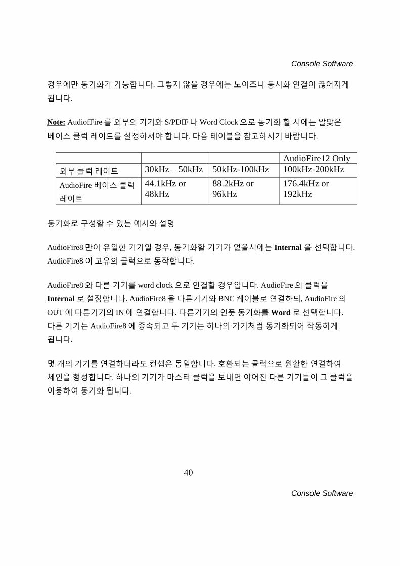
됩니다. Note: AudiofFire 를 외부의 기기와 S/PDIF 나 Word Clock 으로 동기화 할 시에는 알맞은
베이스 클럭 레이트를 설정하셔야 합니다. 다음 테이블을 참고하시기 바랍니다.
AudioFire12 Only 외부 클럭 레이트 30kHz – 50kHz 50kHz-100kHz 100kHz-200kHz
AudioFire 베이스 클럭
레이트
44.1kHz or 48kHz
88.2kHz or 96kHz
176.4kHz or 192kHz
동기화로 구성할 수 있는 예시와 설명 AudioFire8 만이 유일한 기기일 경우, 동기화할 기기가 없을시에는 Internal 을 선택합니다.
AudioFire8 이 고유의 클럭으로 동작합니다. AudioFire8 와 다른 기기를 word clock 으로 연결할 경우입니다. AudioFire 의 클럭을
Internal 로 설정합니다. AudioFire8 을 다른기기와 BNC 케이블로 연결하되, AudioFire 의
OUT 에 다른기기의 IN 에 연결합니다. 다른기기의 인풋 동기화를 Word 로 선택합니다.
다른 기기는 AudioFire8 에 종속되고 두 기기는 하나의 기기처럼 동기화되어 작동하게
됩니다. 몇 개의 기기를 연결하더라도 컨셉은 동일합니다. 호환되는 클럭으로 원활한 연결하여
체인을 형성합니다. 하나의 기기가 마스터 클럭을 보내면 이어진 다른 기기들이 그 클럭을
이용하여 동기화 됩니다.
Console Software
41
Console Software
다수의 AudioFire 사용하기 다수의 AudioFire 가 같이 사용되어 보다 많은 유용성을 제공할 수 있습니다. 그러나 같이
작동하기 위해서는 따라야 할 사항이 있습니다. 다음은 다수의 AudioFire 를 사용함에
있어서 지시와 숙지사항입니다. 컴퓨터에 연결하기 다수의 AudioFire 를 체인처럼(한개의 유닛을 다른 유닛으로 ) FireWire 케이블로 연결해서
혹은 각각의 유닛을 다른 FireWire 단자에 꼽아컴퓨터에 연결할 수 있습니다. AudioFire12s,
AudioFire8s, AudioFire4s 그리고 AudioFire2s 어떠한 순서대로든 연결할 수 있고 마스터
클럭을 보내는 기기는 어떠한 것이 될 수 있습니다. AudioFire12 가 연결되어있으면
192kHz 만이 지원됩니다. Clocking (클럭킹) 다수의 AudioFire 가 사용될 때에는“외부의 기기와의 동기화” 섹션에서 언급한 것처럼
반드시 클럭이 동기화 되어야됩니다. BNC word clock 케이블이나 S/PDIF 케이블을
사용하여 연결합니다. 각각의 AudioFire 가 체인을 이루면서 연결되어야 합니다. 체인의
첫번째 AudioFire 가 클럭 마스타가 되고 나머지는 이에 종속되어 클럭을 따르게 됩니다.
콘솔의 “Settings” 탭에서 각각의 AudioFire 의 클럭을 알맞게 설정하셔야 합니다. 마스터
기기의 세팅은 “Internal” 그리고 나머지는 “Word” clock 이나 “S/PDIF”로
설정되어야합니다. 오디오 작업중 이 설정이 변경되면, 동기화가 깨지게 되고
AudioFire 가 작동을 멈추게 됩니다. 다시 동기화를 진행하고 오디오작업을 다시
시작하여야 합니다.
Console Software
42
Console Software
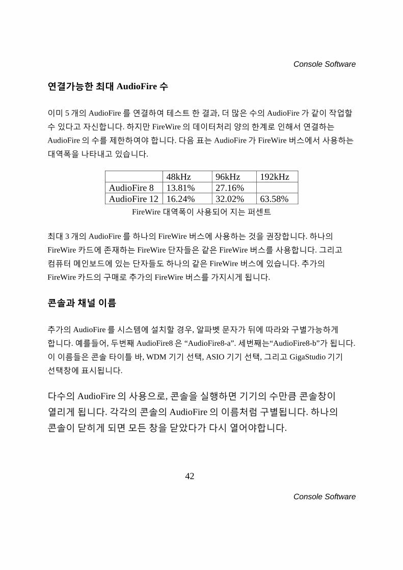
연결가능한 최대 AudioFire 수 이미 5 개의 AudioFire 를 연결하여 테스트 한 결과, 더 많은 수의 AudioFire 가 같이 작업할
수 있다고 자신합니다. 하지만 FireWire 의 데이터처리 양의 한계로 인해서 연결하는
AudioFire 의 수를 제한하여야 합니다. 다음 표는 AudioFire 가 FireWire 버스에서 사용하는
대역폭을 나타내고 있습니다.
48kHz 96kHz 192kHz AudioFire 8 13.81% 27.16% AudioFire 12 16.24% 32.02% 63.58%
FireWire 대역폭이 사용되어 지는 퍼센트 최대 3 개의 AudioFire 를 하나의 FireWire 버스에 사용하는 것을 권장합니다. 하나의
FireWire 카드에 존재하는 FireWire 단자들은 같은 FireWire 버스를 사용합니다. 그리고
컴퓨터 메인보드에 있는 단자들도 하나의 같은 FireWire 버스에 있습니다. 추가의
FireWire 카드의 구매로 추가의 FireWire 버스를 가지시게 됩니다. 콘솔과 채널 이름 추가의 AudioFire 를 시스템에 설치할 경우, 알파벳 문자가 뒤에 따라와 구별가능하게
합니다. 예를들어, 두번째 AudioFire8 은 “AudioFire8-a”. 세번째는“AudioFire8-b”가 됩니다.
이 이름들은 콘솔 타이틀 바, WDM 기기 선택, ASIO 기기 선택, 그리고 GigaStudio 기기
선택창에 표시됩니다. 다수의 AudioFire 의 사용으로, 콘솔을 실행하면 기기의 수만큼 콘솔창이
열리게 됩니다. 각각의 콘솔의 AudioFire 의 이름처럼 구별됩니다. 하나의
콘솔이 닫히게 되면 모든 창을 닫았다가 다시 열어야합니다.
Console Software
43
Console Software
Contacting ECHO Customer Service If you experience any trouble with your ECHO hardware please go to the support area of our website at www.ECHOaudio.com, and check out the “QuickTips” & FAQ’s we have there. If you can’t find a solution to your problem there, please fill out the provided technical support email form. This form will be sent to our technical support staff, and they will respond to you quickly. Please fill out the form completely. The best way to get the help you need is by giving us plenty of detailed information about your computer system, your audio software and hardware, and the problem you are having. We do ask you to please read through this manual and the support area of our website before contacting us. Also, you may find an answer to your problem in the Appendices of this document – starting on the next page. Thank you for buying an ECHO product! Contacting Mackie Customer Service
Note: All Tracktion support issues are handled solely by Mackie. Please do not call ECHO for technical support regarding Tracktion.
You can find helpful information about Tracktion and links to user and support forums on the Internet at:
http://www.mackie.com/products/tracktion/tracktion.html If you are still having problems with Tracktion you can contact Mackie Technical Support here:
http://www.mackie.com/support/index.html
Appendix A: Troubleshooting Guide
44
Appendix A: Troubleshooting Guide
Appendix A: General Troubleshooting Guide Problem: You are unable to install your AudioFire product under Windows 95/98/ME/2000. Solution: There is no driver support for the AudioFire products under Windows 95/98/ME/2000. As stated in the system requirements, you will need Windows XP or Mac OS X (10.3.9 or later) to use your AudioFire product. Problem: When you try to install the drivers from the CDROM, Windows gives you an error message. Solution: You must be logged in as an Administrator to be able to install the Windows drivers. Please see the “Installation” section of this manual for details. Or you may have a ASIO application open in the background. Close all audio applications and attempt to install the driver again. Problem: Your computer spontaneously reboots on you. Solution: You have probably experienced what Microsoft calls a “bug check”, but what everyone else calls the Blue Screen of Death (BSOD). The default setting for the BSOD is not to show the BSOD, but to reboot the computer. This isn’t very helpful for tracking down problems. If you are experiencing blue screens, here’s how you can help us track it down:
• Select Start/Control Panel/System • Go to the Advanced tab and click on the “settings” button in the “Startup
and Recovery” section • Uncheck “Automatically restart” • In the “Write debugging information” section select “Small memory dump”
from the dropdown box • Click OK
Appendix A: Troubleshooting Guide
45
Appendix A: Troubleshooting Guide
Now, next time you get a blue screen, look at it. See if the crash occurred in ECHO1394.sys; if it did, then it’s probably something we need to fix. Restart your computer and find the most recent .dmp file – this is the memory dump. It’s probably in C:\WINDOWS\Minidump. Zip up this .dmp file and send it to [email protected] along with a description of how it happened. This will really help us track down problems. Problem: When you connect a bus powered FireWire device to your AudioFire product it does not receive power. Solution: Your AudioFire product does not pass power from the computer on its FireWire connector. Use a FireWire device with an external power adapter. Problem: You are unable to get your DAT recorder to recognize the S/PDIF output from AudioFire2, AudioFire4 or AudioFire8. Solution: Digital information is transmitted in either of two modes, “professional” or “consumer.” The professional mode is usually implemented in devices that are likely to be used in professional recording environments, whereas the consumer mode is commonly implemented on equipment designed for home use in the consumer market. The primary difference between the two modes is in the implementation of the SCMS copy protection bit, which, in the consumer format, prevents the user from making digital copies of a digital copy. In most professional equipment, this copy-protection bit can be turned off or on according to the user’s needs. In consumer products, the SCMS bit is always enabled. Unfortunately there is no way for the transmitting device to automatically detect which format the receiving device is able to accept. If you have a DAT deck that is not able to read the S/PDIF output from your AudioFire, chances are it is transmitting in the mode that the deck is not equipped to handle. We have provided a software switch in the driver that allows you to select which mode AudioFire8 transmits. To access this switch go to the console. Click on the Settings tab. In the window that appears you’ll see a pair of radio buttons in an
Appendix A: Troubleshooting Guide
46
Appendix A: Troubleshooting Guide
area labeled S/PDIF Format; one radio button is labeled Consumer and the other Professional. Select the appropriate format for your DAT (if you don’t know which one to use, simply select the one that is not currently checked). Now click the Close button and again try recording to your DAT.
Note: AudioFire never transmits the SCMS bit; regardless of which mode is selected.
Problem: When you play an audio file, it plays at an altered pitch. Solution: When your AudioFire product is set to synchronize with an external device, it will play back at the rate generated by that device. For example, if the sound you are playing was sampled at 44.1kHz, but you are synchronized with a device running at 96kHz, the sound will play back at this faster rate. You have four choices - ignore the altered pitch, switch to your AudioFire product’s internal clock, change the sample rate of the external device, or use a different device for the sound playback. Problem: Your AudioFire product doesn’t seem to recognize the synchronization clock to which it is connected. Solution: Although it may seem obvious, the first thing to check is that there is a physical connection between the device generating the clock and your AudioFire product. Just because multiple devices are connected to the same computer doesn’t mean they are synchronized. Next, be sure that you have selected the desired input clock source in the console for your AudioFire product and that the sample rate matches the incoming clock.
Appendix A: Troubleshooting Guide
47
Appendix A: Troubleshooting Guide
Problem: You’re syncing to an external device and suddenly you’ve lost sync. Solution: Whenever your AudioFire product is syncing to an external device and you change the sample rate in that device, you may need to reset the input clock setting in the AudioFire Console software. Just click on the appropriate input clock button to reset it. Problem: Recordings made using the S/PDIF input contain occasional pops or skips. Solution: When recording with the S/PDIF input, you must manually select the S/PDIF clock as the input clock. This can be done from the console. Problem: You’re syncing to an external device and suddenly you’ve lost sync. Solution: Whenever your AudioFire product is syncing to an external device and you change the sample rate in that device, you may need to reset the input clock setting in the ECHO Console software. Just click on the appropriate input clock button to reset it. Problem: The sound cuts in and out, or the left or right channel doesn’t work. Solution: You may have a bad audio cable. Try using a different cable in the problem channel. Problem: There is no sound unless I pull the audio plug out a little. Solution: Not all ¼” plugs are made to the exact same dimensions. Try a plug/cable from a different manufacturer.
Appendix B: Audio Software Guide
48
Appendix B: Audio Software Guide
Appendix B: Audio Software Guide You can use your AudioFire product with any audio software that supports WDM, ASIO or GSIF. That’s a lot of audio software! For most of them, all you need to do is read the software manual to learn how to use them with your AudioFire product. In general, ASIO is preferred for your AudioFire product. ASIO Software Here is a partial list of pro audio software that supports ASIO:
• ACID 4 or higher • Audition 2.0 or higher • Cubase • Kontakt • Logic Audio • Nuendo • Reaktor • Reason • Rebirth • SONAR 2.2 or higher • Sound Forge 8 or higher • Tracktion • Vegas 4 or higher • Wavelab
Appendix C: An Introduction to Digital Recording
49
Appendix C: An Introduction to Digital Recording
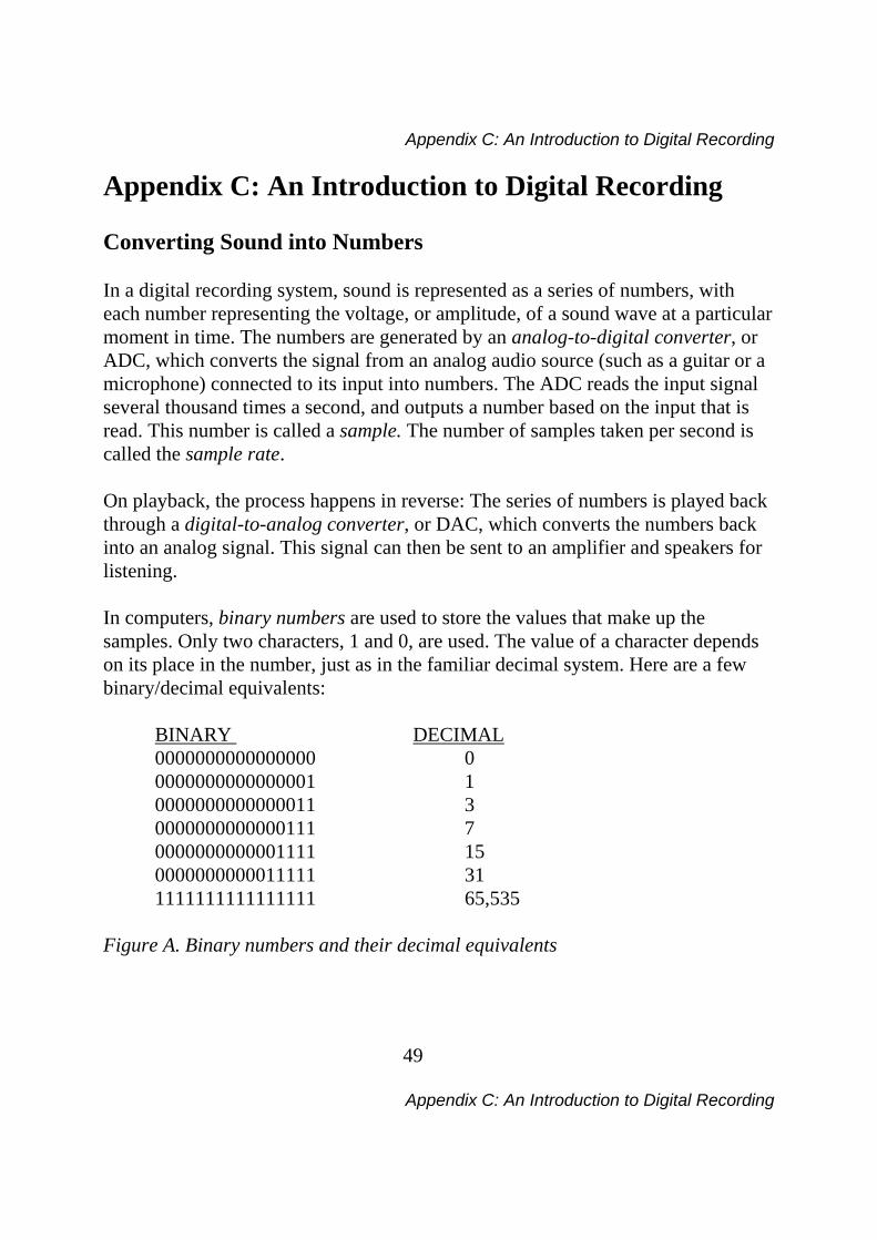
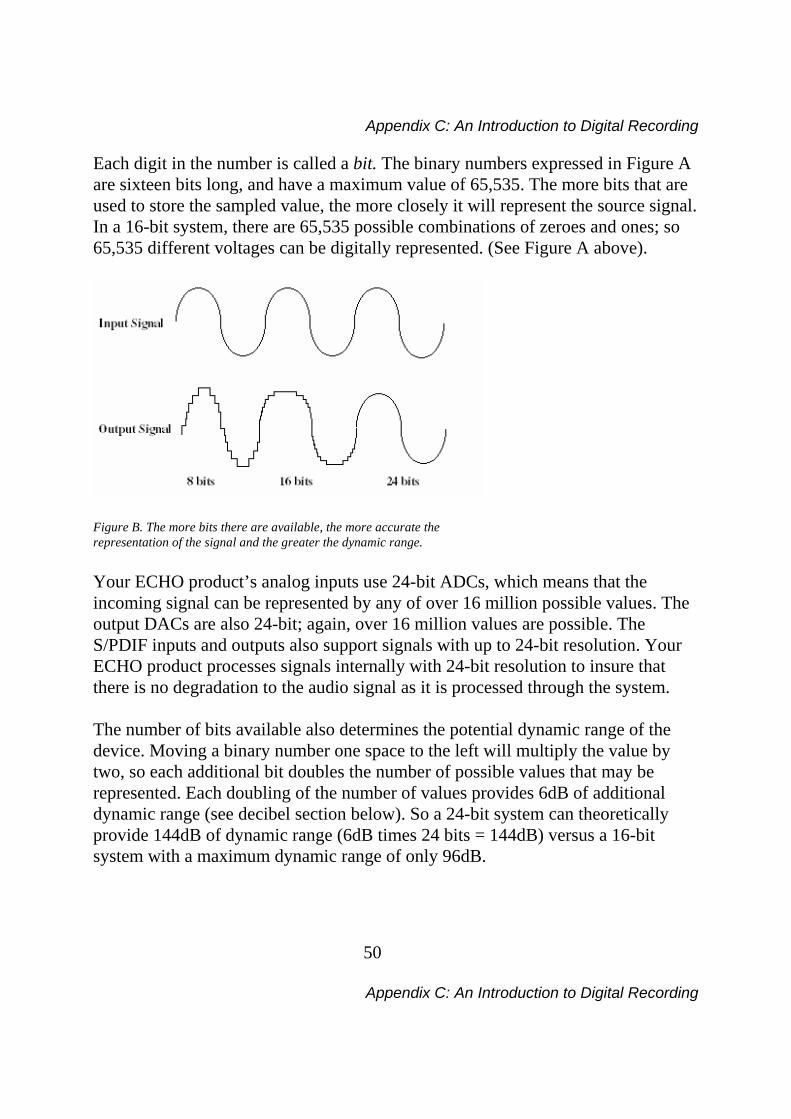
Appendix C: An Introduction to Digital Recording Converting Sound into Numbers In a digital recording system, sound is represented as a series of numbers, with each number representing the voltage, or amplitude, of a sound wave at a particular moment in time. The numbers are generated by an analog-to-digital converter, or ADC, which converts the signal from an analog audio source (such as a guitar or a microphone) connected to its input into numbers. The ADC reads the input signal several thousand times a second, and outputs a number based on the input that is read. This number is called a sample. The number of samples taken per second is called the sample rate. On playback, the process happens in reverse: The series of numbers is played back through a digital-to-analog converter, or DAC, which converts the numbers back into an analog signal. This signal can then be sent to an amplifier and speakers for listening. In computers, binary numbers are used to store the values that make up the samples. Only two characters, 1 and 0, are used. The value of a character depends on its place in the number, just as in the familiar decimal system. Here are a few binary/decimal equivalents: BINARY DECIMAL 0000000000000000 0 0000000000000001 1 0000000000000011 3 0000000000000111 7 0000000000001111 15 0000000000011111 31 1111111111111111 65,535 Figure A. Binary numbers and their decimal equivalents
Appendix C: An Introduction to Digital Recording
50
Appendix C: An Introduction to Digital Recording
Each digit in the number is called a bit. The binary numbers expressed in Figure A are sixteen bits long, and have a maximum value of 65,535. The more bits that are used to store the sampled value, the more closely it will represent the source signal. In a 16-bit system, there are 65,535 possible combinations of zeroes and ones; so 65,535 different voltages can be digitally represented. (See Figure A above).
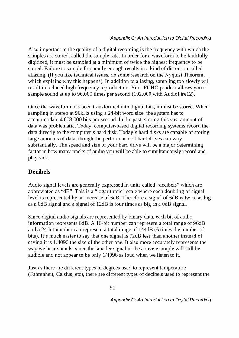
Figure B. The more bits there are available, the more accurate the representation of the signal and the greater the dynamic range. Your ECHO product’s analog inputs use 24-bit ADCs, which means that the incoming signal can be represented by any of over 16 million possible values. The output DACs are also 24-bit; again, over 16 million values are possible. The S/PDIF inputs and outputs also support signals with up to 24-bit resolution. Your ECHO product processes signals internally with 24-bit resolution to insure that there is no degradation to the audio signal as it is processed through the system. The number of bits available also determines the potential dynamic range of the device. Moving a binary number one space to the left will multiply the value by two, so each additional bit doubles the number of possible values that may be represented. Each doubling of the number of values provides 6dB of additional dynamic range (see decibel section below). So a 24-bit system can theoretically provide 144dB of dynamic range (6dB times 24 bits = 144dB) versus a 16-bit system with a maximum dynamic range of only 96dB.
Appendix C: An Introduction to Digital Recording
51
Appendix C: An Introduction to Digital Recording
Also important to the quality of a digital recording is the frequency with which the samples are stored, called the sample rate. In order for a waveform to be faithfully digitized, it must be sampled at a minimum of twice the highest frequency to be stored. Failure to sample frequently enough results in a kind of distortion called aliasing. (If you like technical issues, do some research on the Nyquist Theorem, which explains why this happens). In addition to aliasing, sampling too slowly will result in reduced high frequency reproduction. Your ECHO product allows you to sample sound at up to 96,000 times per second (192,000 with AudioFire12). Once the waveform has been transformed into digital bits, it must be stored. When sampling in stereo at 96kHz using a 24-bit word size, the system has to accommodate 4,608,000 bits per second. In the past, storing this vast amount of data was problematic. Today, computer-based digital recording systems record the data directly to the computer’s hard disk. Today’s hard disks are capable of storing large amounts of data, though the performance of hard drives can vary substantially. The speed and size of your hard drive will be a major determining factor in how many tracks of audio you will be able to simultaneously record and playback. Decibels Audio signal levels are generally expressed in units called “decibels” which are abbreviated as “dB”. This is a “logarithmic” scale where each doubling of signal level is represented by an increase of 6dB. Therefore a signal of 6dB is twice as big as a 0dB signal and a signal of 12dB is four times as big as a 0dB signal. Since digital audio signals are represented by binary data, each bit of audio information represents 6dB. A 16-bit number can represent a total range of 96dB and a 24-bit number can represent a total range of 144dB (6 times the number of bits). It’s much easier to say that one signal is 72dB less than another instead of saying it is 1/4096 the size of the other one. It also more accurately represents the way we hear sounds, since the smaller signal in the above example will still be audible and not appear to be only 1/4096 as loud when we listen to it. Just as there are different types of degrees used to represent temperature (Fahrenheit, Celsius, etc), there are different types of decibels used to represent the
Appendix C: An Introduction to Digital Recording
52
Appendix C: An Introduction to Digital Recording
level of analog audio signals. The most common are dBu and dBV decibels. Both of these represent voltage levels and still double for every increase of 6dB. It is only the reference point, or 0dB level that is different. A 0dBV signal has a voltage level of 1.0 volts. A 0dBu signal has a voltage level of .775 volts. Since .775 is approximately 2dB less than 1.0, converting dBV levels into dBu levels is as simple as subtracting 2dB (2.21 to be exact). Signals are also occasionally represented with units of dBm. This is an older unit that measures power instead of voltage levels with 0dBm representing 1 milliwatt. Earlier tube-based audio equipment used standardized input and output impedances of 600 ohms, so a 0dBm signal was produced with a voltage of .775 volts. Since most of today’s equipment uses impedances other than 600 ohms, it is more useful to represent signals by voltages rather than power and the dBu unit was introduced. A signal level of 0dBu is identical to a level of 0dBm. Digital signals, after they are recorded, no longer directly represent any physical quantity such as voltage or power and 0dB is generally used to represent a “full-scale” or maximum signal level. All other signal levels are lower and are expressed as negative decibels. Most meters on digital equipment have 0dB at the top and range downward from there. A signal that is 30dB below full scale would simply be referred to as a –30dB signal. Nominal Signal Levels and Headroom Today’s equipment is generally referred to as +4dBu equipment (professional) or –10dBV equipment (consumer). These levels are the typical or “nominal” signal levels you can expect to see with professional (studio) equipment such as mixers or with consumer equipment such as home stereos and CD players. A +4dBu signal has a voltage level of 1.23 volts and a –10dBV signal has a voltage level of .316 volts.
Appendix C: An Introduction to Digital Recording
53
Appendix C: An Introduction to Digital Recording
The above nominal levels represent typical or average levels that are often exceeded when recording loud signals such as drum beats. The difference between the nominal level and the loudest signal that can be recorded without clipping is called “headroom”. Your ECHO product provides approximately 14dB of headroom allowing an 18dBu signal to be recorded. Unbalanced and Balanced Inputs and Outputs An unbalanced signal, commonly used for guitars and consumer electronics, contains two components, a ground signal and a “hot” or active signal. The ground is the barrel of a ¼” connector and the shell of an “RCA” style connector. A balanced signal contains two active signals instead of one in addition to the ground. These are referred to as the “plus” and “minus” signals. A balanced input amplifier amplifies the difference between these two signals. Any extraneous noise picked up from power lines or other sources will appear equally on both the plus and minus inputs. This is called “common mode” noise since it is common to both signals and the input amplifier will subtract the noise on the minus input from the noise on the plus input. If the input amplifier is perfectly balanced and the noise on both plus and minus is precisely equal, the noise will completely cancel out. In the real world this is not the case and some of the common mode noise will still make it through, although at a much reduced level. How well an input amplifier rejects this common mode noise is called the “common mode rejection ratio” (abbreviated as CMRR) and is expressed in dB. Balanced outputs typically drive the plus and minus components of a balanced signal in one of two ways. A “differentially” balanced output signal is one where the minus output is the mirror image of the plus output. That is, if the “plus” output is at +1 volt, then the “minus” output is at –1 volt. An “impedance” balanced output provides most of the benefits of a differentially balanced output at a lower cost. In this case only the plus component actually carries the signal. The minus component is tied to ground through a resistor so that the output impedance matches that of the plus component. Since the impedances
Appendix C: An Introduction to Digital Recording
54
Appendix C: An Introduction to Digital Recording
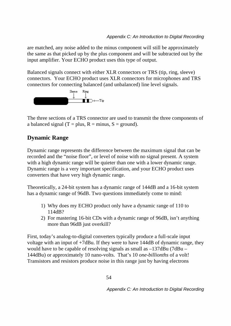
are matched, any noise added to the minus component will still be approximately the same as that picked up by the plus component and will be subtracted out by the input amplifier. Your ECHO product uses this type of output. Balanced signals connect with either XLR connectors or TRS (tip, ring, sleeve) connectors. Your ECHO product uses XLR connectors for microphones and TRS connectors for connecting balanced (and unbalanced) line level signals.
The three sections of a TRS connector are used to transmit the three components of a balanced signal (T = plus, R = minus, S = ground). Dynamic Range Dynamic range represents the difference between the maximum signal that can be recorded and the “noise floor”, or level of noise with no signal present. A system with a high dynamic range will be quieter than one with a lower dynamic range. Dynamic range is a very important specification, and your ECHO product uses converters that have very high dynamic range. Theoretically, a 24-bit system has a dynamic range of 144dB and a 16-bit system has a dynamic range of 96dB. Two questions immediately come to mind:
1) Why does my ECHO product only have a dynamic range of 110 to 114dB?
2) For mastering 16-bit CDs with a dynamic range of 96dB, isn’t anything more than 96dB just overkill?
First, today’s analog-to-digital converters typically produce a full-scale input voltage with an input of +7dBu. If they were to have 144dB of dynamic range, they would have to be capable of resolving signals as small as –137dBu (7dBu – 144dBu) or approximately 10 nano-volts. That’s 10 one-billionths of a volt! Transistors and resistors produce noise in this range just by having electrons
Appendix C: An Introduction to Digital Recording
55
Appendix C: An Introduction to Digital Recording
moving around due to heat. Even if the converters could be perfectly designed to read these levels, the low noise requirements of the surrounding circuitry such as power supplies and amplifiers would be so stringent that they would either be impossible or too expensive to build. In answering the second question, consider the fact that music is often compressed or amplified after it is recorded, and that some headroom is necessary when recording to avoid clipping. The only way that 96dB would be adequate is if all music were recorded so that the peaks were just under full-scale and no compression or amplification was going to be applied after recording. Any time recorded music is amplified, so is the noise at the low end. Your ECHO product has enough dynamic range to allow sufficient headroom and post-processing to be applied while still keeping the noise either off the recording completely or down as far as possible.
Appendix D: Specifications
56
Appendix D: Specifications
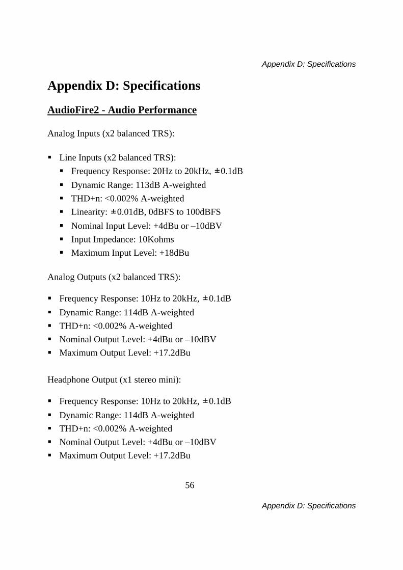
Appendix D: Specifications AudioFire2 - Audio Performance Analog Inputs (x2 balanced TRS): Line Inputs (x2 balanced TRS):
Frequency Response: 20Hz to 20kHz, ±0.1dB Dynamic Range: 113dB A-weighted THD+n: <0.002% A-weighted Linearity: ±0.01dB, 0dBFS to 100dBFS Nominal Input Level: +4dBu or –10dBV Input Impedance: 10Kohms Maximum Input Level: +18dBu
Analog Outputs (x2 balanced TRS): Frequency Response: 10Hz to 20kHz, ±0.1dB Dynamic Range: 114dB A-weighted THD+n: <0.002% A-weighted Nominal Output Level: +4dBu or –10dBV Maximum Output Level: +17.2dBu
Headphone Output (x1 stereo mini): Frequency Response: 10Hz to 20kHz, ±0.1dB Dynamic Range: 114dB A-weighted THD+n: <0.002% A-weighted Nominal Output Level: +4dBu or –10dBV Maximum Output Level: +17.2dBu
Appendix D: Specifications
57
Appendix D: Specifications
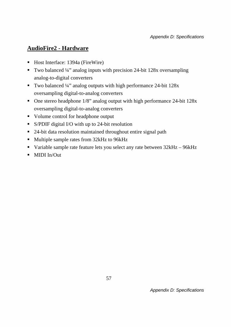
AudioFire2 - Hardware Host Interface: 1394a (FireWire) Two balanced ¼” analog inputs with precision 24-bit 128x oversampling
analog-to-digital converters Two balanced ¼” analog outputs with high performance 24-bit 128x
oversampling digital-to-analog converters One stereo headphone 1/8” analog output with high performance 24-bit 128x
oversampling digital-to-analog converters Volume control for headphone output S/PDIF digital I/O with up to 24-bit resolution 24-bit data resolution maintained throughout entire signal path Multiple sample rates from 32kHz to 96kHz Variable sample rate feature lets you select any rate between 32kHz – 96kHz MIDI In/Out
Appendix D: Specifications
58
Appendix D: Specifications
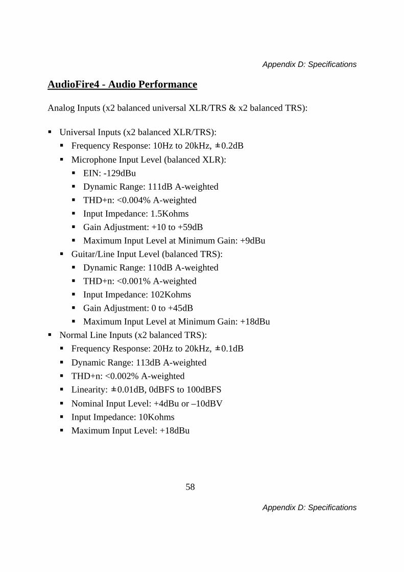
AudioFire4 - Audio Performance Analog Inputs (x2 balanced universal XLR/TRS & x2 balanced TRS): Universal Inputs (x2 balanced XLR/TRS):
Frequency Response: 10Hz to 20kHz, ±0.2dB Microphone Input Level (balanced XLR):
EIN: -129dBu Dynamic Range: 111dB A-weighted THD+n: <0.004% A-weighted Input Impedance: 1.5Kohms Gain Adjustment: +10 to +59dB Maximum Input Level at Minimum Gain: +9dBu
Guitar/Line Input Level (balanced TRS): Dynamic Range: 110dB A-weighted THD+n: <0.001% A-weighted Input Impedance: 102Kohms Gain Adjustment: 0 to +45dB Maximum Input Level at Minimum Gain: +18dBu
Normal Line Inputs (x2 balanced TRS): Frequency Response: 20Hz to 20kHz, ±0.1dB Dynamic Range: 113dB A-weighted THD+n: <0.002% A-weighted Linearity: ±0.01dB, 0dBFS to 100dBFS Nominal Input Level: +4dBu or –10dBV Input Impedance: 10Kohms Maximum Input Level: +18dBu
Appendix D: Specifications
59
Appendix D: Specifications
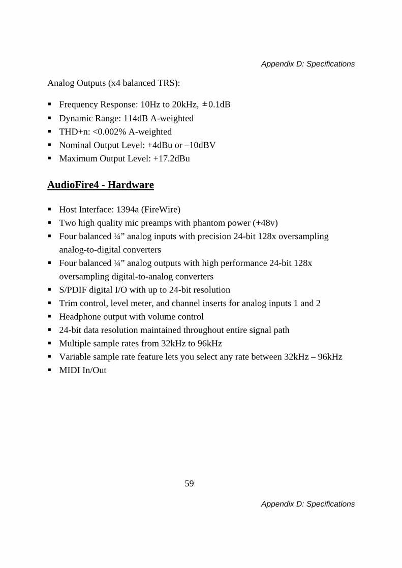
Analog Outputs (x4 balanced TRS): Frequency Response: 10Hz to 20kHz, ±0.1dB Dynamic Range: 114dB A-weighted THD+n: <0.002% A-weighted Nominal Output Level: +4dBu or –10dBV Maximum Output Level: +17.2dBu
AudioFire4 - Hardware Host Interface: 1394a (FireWire) Two high quality mic preamps with phantom power (+48v) Four balanced ¼” analog inputs with precision 24-bit 128x oversampling
analog-to-digital converters Four balanced ¼” analog outputs with high performance 24-bit 128x
oversampling digital-to-analog converters S/PDIF digital I/O with up to 24-bit resolution Trim control, level meter, and channel inserts for analog inputs 1 and 2 Headphone output with volume control 24-bit data resolution maintained throughout entire signal path Multiple sample rates from 32kHz to 96kHz Variable sample rate feature lets you select any rate between 32kHz – 96kHz MIDI In/Out

Appendix D: Specifications
60
Appendix D: Specifications
AudioFire8 - Audio Performance Analog Inputs (x2 balanced universal XLR/TRS & x6 balanced TRS): Universal Inputs (x2 balanced XLR/TRS):
Frequency Response: 10Hz to 20kHz, ±0.2dB Microphone Input Level (balanced XLR):
EIN: -129dBu Dynamic Range: 111dB A-weighted THD+n: <0.004% A-weighted Input Impedance: 1.5Kohms Gain Adjustment: +10 to +59dB Maximum Input Level at Minimum Gain: +9dBu
Guitar/Line Input Level (balanced TRS): Dynamic Range: 110dB A-weighted THD+n: <0.001% A-weighted Input Impedance: 102Kohms Gain Adjustment: 0 to +45dB Maximum Input Level at Minimum Gain: +18dBu
Normal Line Inputs (x6 balanced TRS): Frequency Response: 20Hz to 20kHz, ±0.1dB Dynamic Range: 113dB A-weighted THD+n: <0.002% A-weighted Linearity: ±0.01dB, 0dBFS to 100dBFS Nominal Input Level: +4dBu or –10dBV Input Impedance: 10Kohms Maximum Input Level: +18dBu
Appendix D: Specifications
61
Appendix D: Specifications
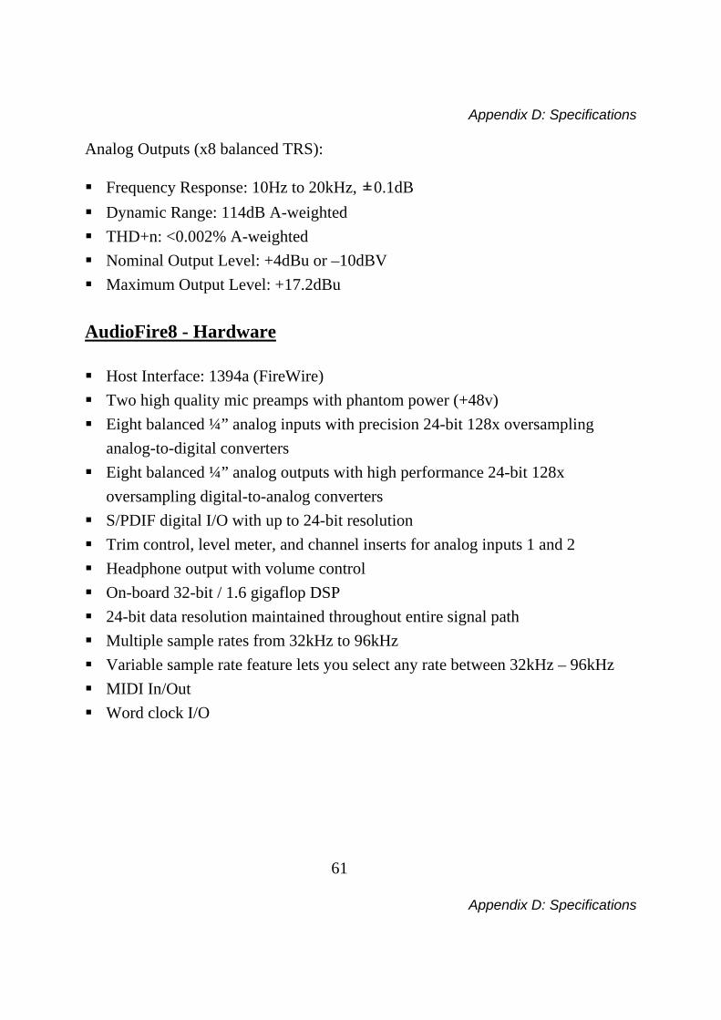
Analog Outputs (x8 balanced TRS): Frequency Response: 10Hz to 20kHz, ±0.1dB Dynamic Range: 114dB A-weighted THD+n: <0.002% A-weighted Nominal Output Level: +4dBu or –10dBV Maximum Output Level: +17.2dBu
AudioFire8 - Hardware Host Interface: 1394a (FireWire) Two high quality mic preamps with phantom power (+48v) Eight balanced ¼” analog inputs with precision 24-bit 128x oversampling
analog-to-digital converters Eight balanced ¼” analog outputs with high performance 24-bit 128x
oversampling digital-to-analog converters S/PDIF digital I/O with up to 24-bit resolution Trim control, level meter, and channel inserts for analog inputs 1 and 2 Headphone output with volume control On-board 32-bit / 1.6 gigaflop DSP 24-bit data resolution maintained throughout entire signal path Multiple sample rates from 32kHz to 96kHz Variable sample rate feature lets you select any rate between 32kHz – 96kHz MIDI In/Out Word clock I/O
Appendix D: Specifications
62
Appendix D: Specifications
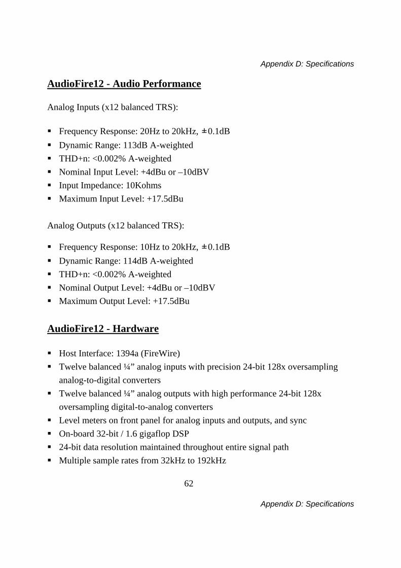
AudioFire12 - Audio Performance Analog Inputs (x12 balanced TRS): Frequency Response: 20Hz to 20kHz, ±0.1dB Dynamic Range: 113dB A-weighted THD+n: <0.002% A-weighted Nominal Input Level: +4dBu or –10dBV Input Impedance: 10Kohms Maximum Input Level: +17.5dBu
Analog Outputs (x12 balanced TRS): Frequency Response: 10Hz to 20kHz, ±0.1dB Dynamic Range: 114dB A-weighted THD+n: <0.002% A-weighted Nominal Output Level: +4dBu or –10dBV Maximum Output Level: +17.5dBu
AudioFire12 - Hardware Host Interface: 1394a (FireWire) Twelve balanced ¼” analog inputs with precision 24-bit 128x oversampling
analog-to-digital converters Twelve balanced ¼” analog outputs with high performance 24-bit 128x
oversampling digital-to-analog converters Level meters on front panel for analog inputs and outputs, and sync On-board 32-bit / 1.6 gigaflop DSP 24-bit data resolution maintained throughout entire signal path Multiple sample rates from 32kHz to 192kHz
Appendix D: Specifications
63
Appendix D: Specifications
Variable sample rate feature lets you select any rate between 32kHz – 192kHz MIDI In/Out Word clock I/O
Index
64
Index
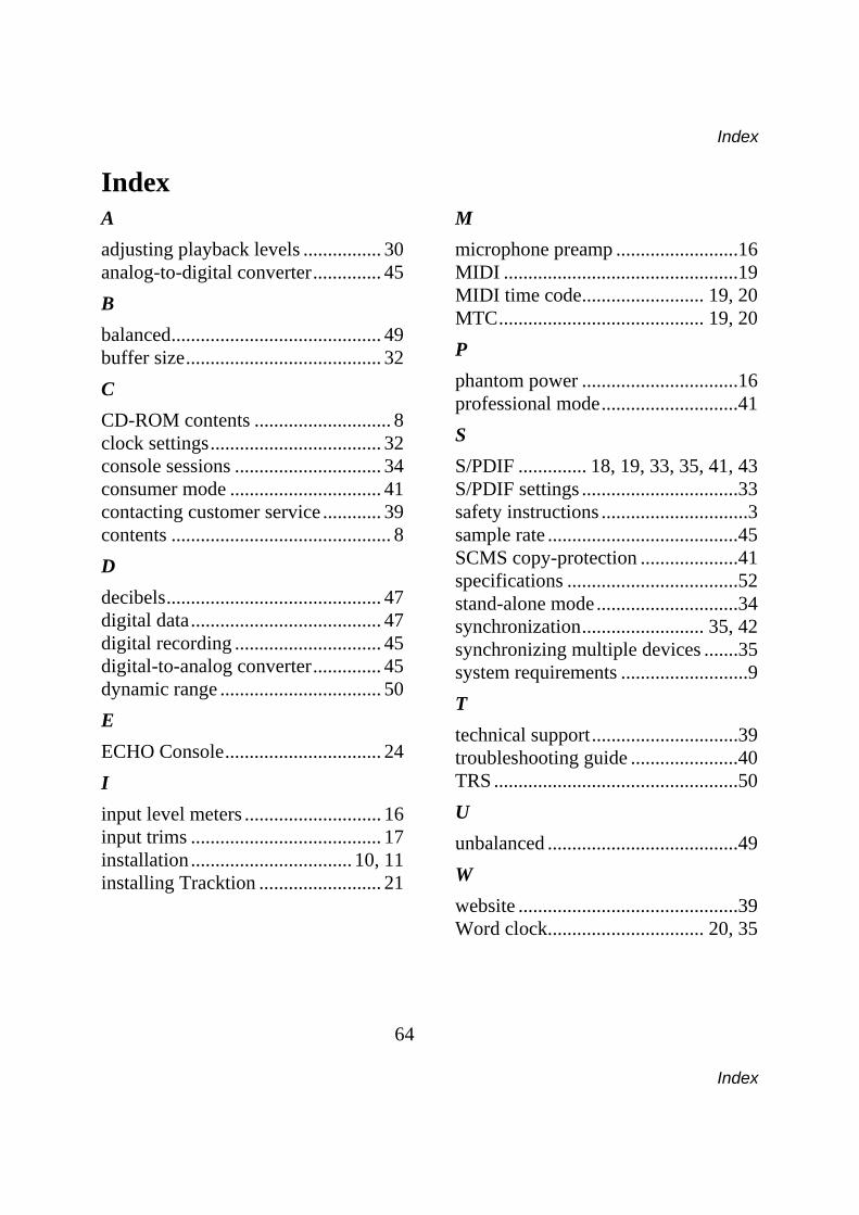
Index A adjusting playback levels ................ 30 analog-to-digital converter.............. 45 B balanced........................................... 49 buffer size........................................ 32 C CD-ROM contents ............................ 8 clock settings................................... 32 console sessions .............................. 34 consumer mode ............................... 41 contacting customer service ............ 39 contents ............................................. 8 D decibels............................................ 47 digital data....................................... 47 digital recording .............................. 45 digital-to-analog converter.............. 45 dynamic range ................................. 50 E ECHO Console................................ 24 I input level meters ............................ 16 input trims ....................................... 17 installation................................. 10, 11 installing Tracktion ......................... 21
M microphone preamp .........................16 MIDI ................................................19 MIDI time code......................... 19, 20 MTC.......................................... 19, 20 P phantom power ................................16 professional mode............................41 S S/PDIF .............. 18, 19, 33, 35, 41, 43 S/PDIF settings ................................33 safety instructions ..............................3 sample rate .......................................45 SCMS copy-protection ....................41 specifications ...................................52 stand-alone mode.............................34 synchronization......................... 35, 42 synchronizing multiple devices .......35 system requirements ..........................9 T technical support..............................39 troubleshooting guide ......................40 TRS ..................................................50 U unbalanced .......................................49 W website .............................................39 Word clock................................ 20, 35