Embed Size (px)
Citation preview

- 140 -
Chapter – 12 Heat Exchangers for Industrial Refrigeration Systems Copy Right By:
Thomas T.S. Wan 温到祥 著
Sept. 3, 2008 All rights reserved This section deals with the heat exchangers used for industrial refrigeration application, such as air cooled condenser, evaporative condenser, water cooled condenser and shell-and-tube evaporators. Other types of heat exchangers such as pipe-coil, unit coolers, product coolers, plate type heat exchanger, coil-and-drum, pipe-in-pipe, air-to-air, fluid-to-gas or gas-to-fluid or oil coolers are not covered in this section. Condensing Ton and Evaporative Ton: When dealing with heat transfer, the heat transfer unit is Btu/Hr. Evaporative ton or ton of refrigeration is 12,000 Btu/Hr. However, if the heat transfer ton is referred to the heat rejection from condenser, it is the condensing ton. The condensing ton is not 12,000 Btu/Hr, it is 14,545 Btu/Hr. Condensing Ton = 1 TR + 1 HP = 12,000 + 2,545 = 14,545 Btu/Hr The condensing ton is only used for the term of Sq.Ft/ton for water cooled condenser curves. To avoid any confusion, the condensing ton is not used for heat rejection calculation. System Heat Rejection to Condenser: Heat rejection = TR x 12000 + BHP x 2545 Heat rejction = Btu/Hr TR = Tons of Refrigeration BHP = Compressor BHP at design load For example: 500 TR, power consumption is 625 BHP Heat rejection = 500 x 12,000 + 625 x 2545 = 6,000,000 + 1,590,625 = 7,590,625 Btu/Hr Note: If screw compressor is used and it is with water cooled oil cooling,
the heat rejection to condenser should be: Heat rejection = TR x 12000 + BHP x 2545 – Oil Cooling Heat Removal
- 141 -
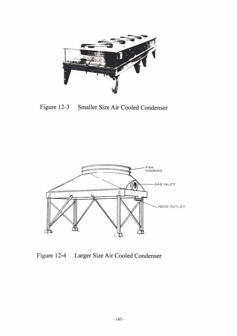
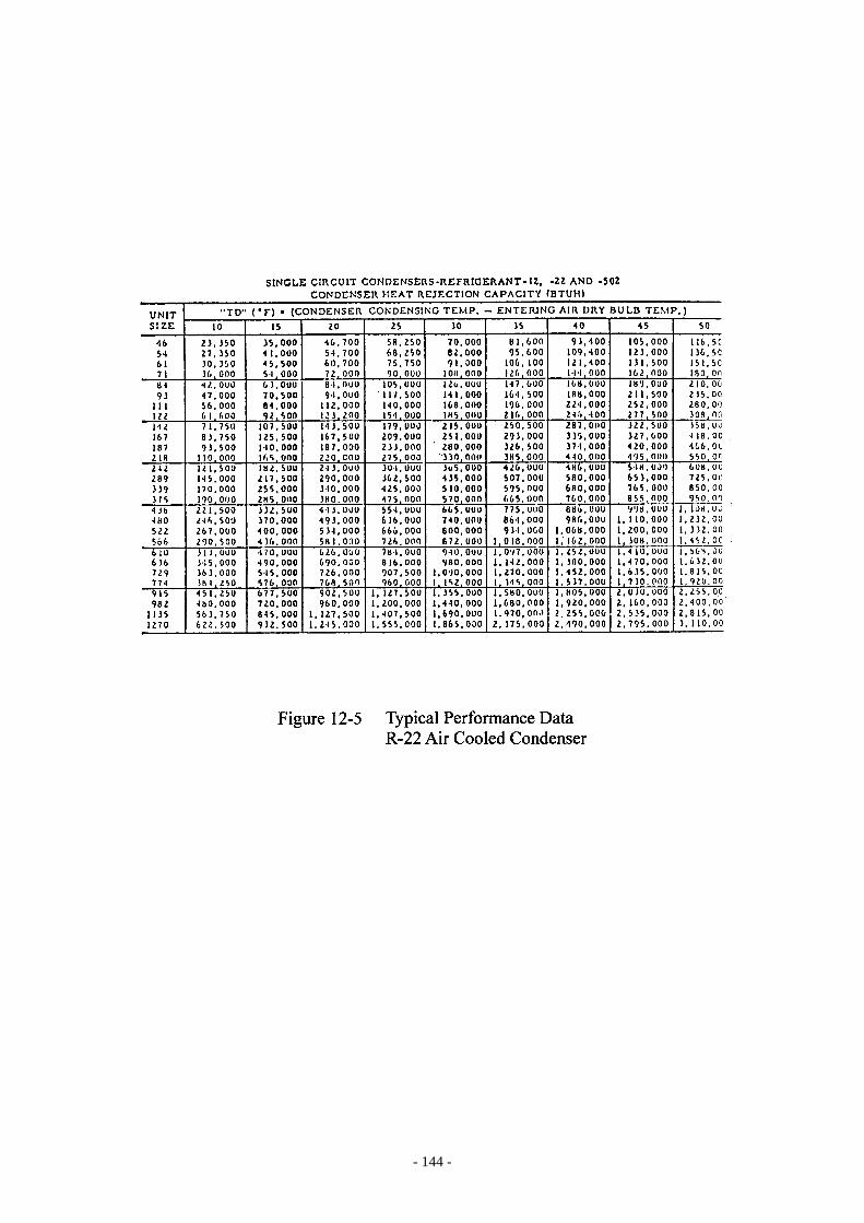
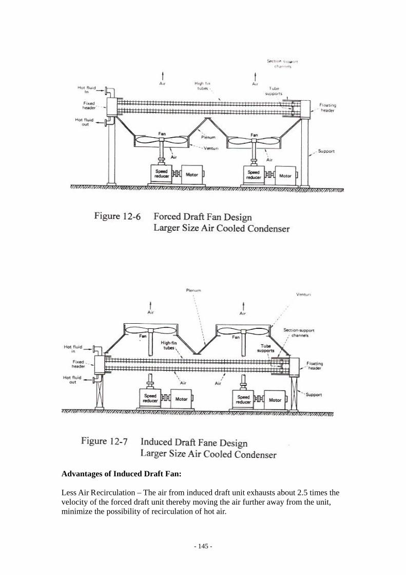
Air Cooled Condensers Basically, air cooled condensers are mostly used for the installation where water is not available or it is economically justified to use air cooled instead of water cooled for large refrigeration installation. In most cases, use of air cooled condenser could result in higher cost and higher power consumption as compared to water cooled condenser project. Figure 12-1 shows a typical construction of an air cooled condenser. An air cooled condenser consists of a fan section, a coil section, casing and supporting structure. Figure 12-2 shows the belt driving fan assembly for the air cooled condenser. Figure 12-3 is a smaller size air cooled condenser and the Figure 12-4 is a typical larger size air cooled condenser. The performance of the air cooled condenser is as the following: CT = ADB + TD CT = Condensing Temperature,℉ ADB = Entering Dry Bulb Air Temperature, ℉ TD = Approach, ℉ The approach for the air cooled condenser is the temperature difference between the design condensing temperature and the design outdoor ambient temperature; smaller approach requires a larger size condenser because more heat transfer coil surface is needed; larger TD permits a smaller air cooled condenser because less heat transfer coil surface is required for the heat rejection. Figure 12-5 is the typical air cooled condenser performance data sheet. The performance sheet shows the condenser has less heat rejection capacity at a smaller TD and higher heat rejection capacity at a higher TD. What TD should be used depends on the maximum DWP (design working pressure) of the condensing coil and the refrigerant being used. Most installations use a TD between 15℉ to 30℉. The air cooled condenser is getting expensive if the TD is less than 15℉ and the DWP of high side is getting too high if the TD is more than 30℉, unless the ambient design dry bulb temperature is low. The power consumption will be higher if the TD is higher for the system; the condenser size is smaller, but the compressor and driving motor is more expensive. For small and medium size installation, the condenser can have either horizontal fan discharge or vertical discharge. Also, two types of fan draft flow for the condenser: one is Draw Through (Induced Draft) design and the other is Blow Through (Forced Draft) design. Most large size air cooled condensers are with vertical air discharge. Figure 12-6 shows a typical large air cooled condenser with a forced draft fan; Figure 12-7 is a typical large air cooled condenser with an induced draft fan.

- 142 -
- 143 -
- 144 -
- 145 -
Advantages of Induced Draft Fan: Less Air Recirculation – The air from induced draft unit exhausts about 2.5 times the velocity of the forced draft unit thereby moving the air further away from the unit, minimize the possibility of recirculation of hot air.
- 146 -
Induced draft units are more efficient – The inlet air more uniformly covers the bottom rows of tubes. Might require less fan horsepower – Induced Draft unit could move more air at same fan horsepower than Forced Draft unit. Protect bundles from atmospheric corrosion – The exhaust hoods of the Induced Draft unit cover the top of the units; minimize the amount of rain that drops into the fan ring. It might require less maintenance for corrosion protection. Better operational heat transfer – Hood cover shields the tube from direct rays of the sun, more uniform cooling. Minimum data required for air cooled condenser selection and pricing: The followings are the minimum data required to make an air cooled condenser selection or to make quotation proposal: 1.0 Heat rejection, Btu/Hr. 2.0 Refrigerant. 3.0 Ambient air temperature. 4.0 Condensing temperature. 5.0 Vertical or horizontal arrangement, Blow Through or Draw Through fan. 6.0 Centrifugal, propeller or vane axial fan. 7.0 Type of motor, power supply and code requirements. 8.0 Special coil material requirement, if any. 9.0 Special supporting structure, if any. 10.0 Type of head control, if required. Head Control Requirement: Since air cooled condensers are often required to operate over a wide range of ambient air temperatures and variable loading conditions, therefore, air cooled condenser tends to run a very low head pressure when operating in a low ambient air temperature. It is a good practice to take advantage of the falling condensing temperature to save the power consumption. However, the system must maintain a minimum head pressure in order to keep system pressure differential high enough to allow the controls and expansion devices function properly. Therefore, refrigeration application should have head control provision to allow the system operating pressure to vary with the ambient air temperature within certain limits, but without adversely affecting the system operation. Various Head Controls for Air Cooled Condenser: A) Fan Cycling Control. Individual fan of a multiple fans can be cycled to maintain the condensing
temperature of the system. This is most commonly used control for air cooled condenser particularly for small size installations.

- 147 -
B) Face Dampers. This is good for low ambient temperature installation. Air flow reduction
through the condenser coil can be accomplished with closing the face damper. Damper motor(s) is controlled by ambient sensing thermostat or condenser head pressure sensing switch.
C) Flooding-Type Condenser Control and Low Ambient Operation. Head control valve will partially close the liquid to receiver to flood the
condenser coil to maintain the preset pressure for the condenser. An automatic hot gas valve provides pressure differential between compressor discharge and receiver o no less than 30 Psi.
This type of condenser pressure control is effective for cold climates even
below 0°F. The receiver must be sized large enough to hold the extra amount of liquid for
the coil flooding. Low Ambient Bypass Timer - A five minute time delay to bypass the low
pressure cutout during low ambient startup. D) Two-Speed Fan Control or Variable Speed Fan Control. Two speed fan control or variable fan speed control provides more fine tune of
head control for the air cooled condenser. Variable Fan Pitch Head Control for Large Size Air Cooled Condenser: In additional to the methods of the head controls available for smaller size air cooled condenser, the other head control available for larger size air condenser is the Automatic Variable Pitch Fan Control. This is to control the pitch of the fan to vary the air volume flow to control the temperature or condensing pressure. System Shut Down During Cold Ambient: In case the refrigeration system is shut down during cold ambient, protection against refrigerant migrant in the system should be considered. These protections are such as drain off process fluid in the evaporator if the process fluid will freeze in low ambient; or the refrigerant in the system is to be pumped out into storage receiver or the service valves for the condenser are to be shut off. Piping and Parallel Multiple Unit Application: Piping hook-up and the recommendations for parallel multiple units operation are mostly the same as for the evaporative condenser.

- 148 -
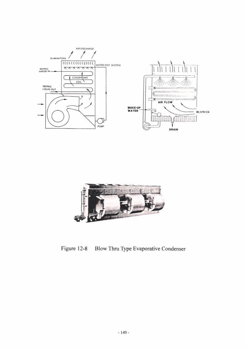
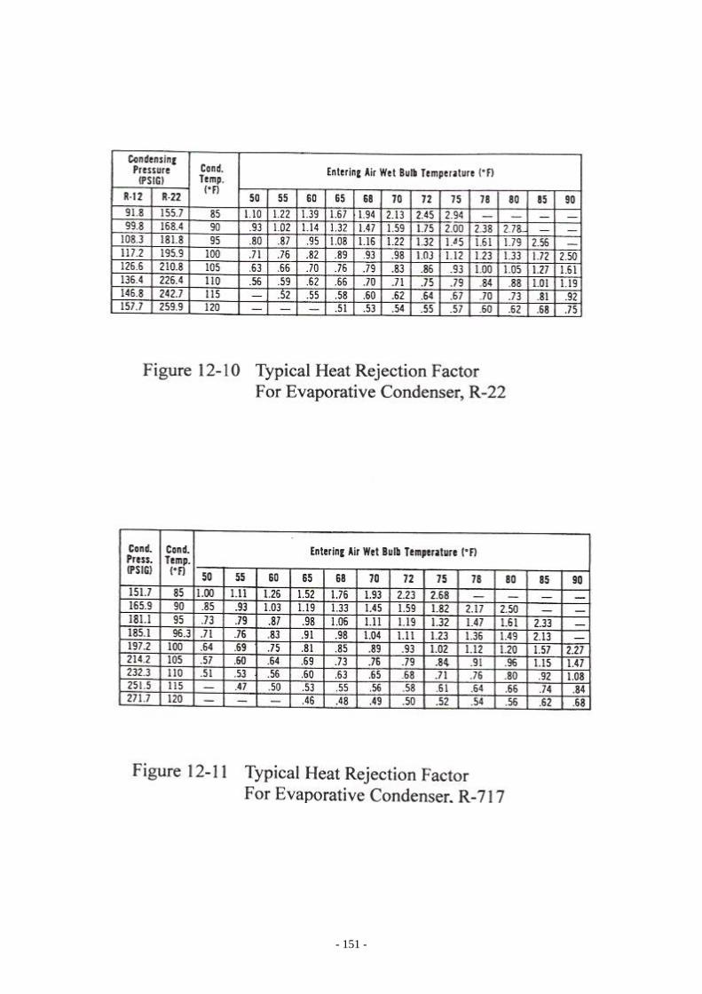
Evaporative Condensers Evaporative condenser is the same as air cooled condenser except water spray is added to wet the entire condensing coil. The water circulation rate for the evaporative condenser is about 1 GPM/Ton. Most evaporative condensers are with vertical discharge. Fan draft flow is Blow Thru or Induce Draft. Figure 12-8 shows the Blow Thru type evaporative condenser. Figure 12-9 shows the Induce Draft type design. Fans available for evaporative condenser are axial, vane axial or centrifugal. The performance of an evaporative condenser is rated by °F of Approach. Deg.F Approach = CT – FWB CT = Condensing Temperature, °F FWB = Wetbulb Air Temperature, °F Therefore: CT = °F Approach + FWB For example: Wetbulb Air Temperature is 80°FWB Approach is 10°F CT = 10°F + 80°F = 90°F Figure 12-10 is the typical heat rejection factors for R-22 for various approaches between condensing temperature and air °FWB for a typical evaporative condenser; Figure 12-11 is the typical heat rejection factors for R-717 at various approaches. Those heat rejection factors are to be applied for the determination of the size of the evaporative condenser. Higher the factor, larger size of the evaporative condenser is required. The heat rejection factor will be larger if the approach between the CT and °FWB is smaller. Generally speaking, the minimum approach is about 10°F for most applications. For special application the approach could be 5~6°F; however, the evaporative condenser would be huge and expensive. Head Control Methods for Evaporative Condenser: The head controls for evaporative condenser, such as variable speed drive and multiple fan cycling are the same as for the air cooled condenser except the following: 1.0 Automatic Capacity Control Damper control:
(a) Damper installed in the centrifugal fan housings – This is to use the damper to modulate the quantity of air flowing through the unit. When
- 149 -

- 150 -
- 151 -
- 152 -
the dampers close to their minimum air flow position, an auxiliary switch will turn off the fan motor.
(b) The discharge hood and damper – The dampers are to be fully open
before the fans are running and closed when the fan is off. The damper actuator is controlled by a temperature controller.
2.0 Water Pump Variable Speed Control. And Water Pump On-Off Reduction of air or water flow would greatly reduce the capacity. Therefore,
shutting off the water flow should be done only after other means of control have been used.
The Head Control Function Sequence for evaporative condenser: On decreasing ambient temperature in winter time:
A. Fan speed reduction. B. Fans cycling. C. Damper closing. D. Pump cycling. On condensing pressure increasing: a. Fan speed increase. b. Fans cycling. c. Damper opens. d. Pump cycle on.
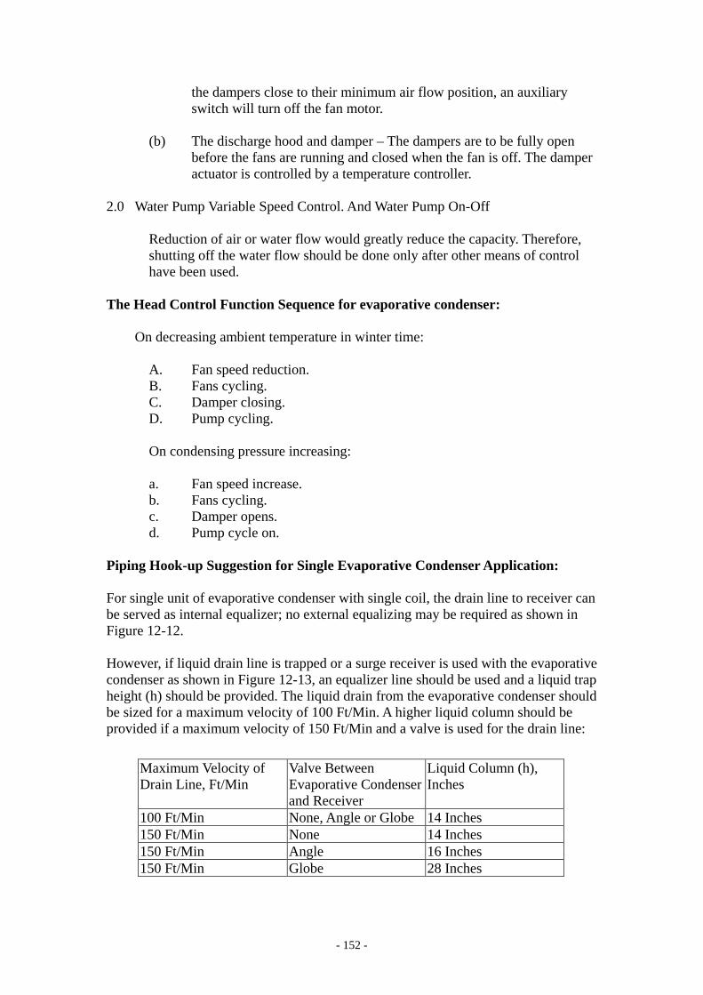
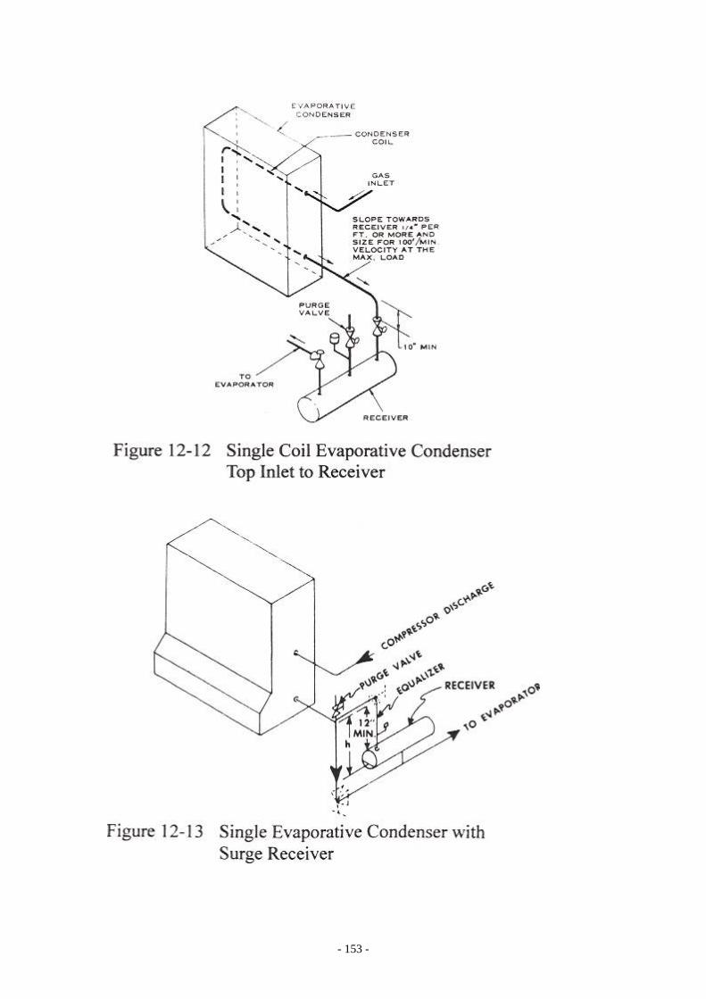
Piping Hook-up Suggestion for Single Evaporative Condenser Application: For single unit of evaporative condenser with single coil, the drain line to receiver can be served as internal equalizer; no external equalizing may be required as shown in Figure 12-12. However, if liquid drain line is trapped or a surge receiver is used with the evaporative condenser as shown in Figure 12-13, an equalizer line should be used and a liquid trap height (h) should be provided. The liquid drain from the evaporative condenser should be sized for a maximum velocity of 100 Ft/Min. A higher liquid column should be provided if a maximum velocity of 150 Ft/Min and a valve is used for the drain line:
Maximum Velocity of Drain Line, Ft/Min
Valve Between Evaporative Condenser and Receiver
Liquid Column (h), Inches
100 Ft/Min None, Angle or Globe 14 Inches 150 Ft/Min None 14 Inches 150 Ft/Min Angle 16 Inches 150 Ft/Min Globe 28 Inches
- 153 -

- 154 -
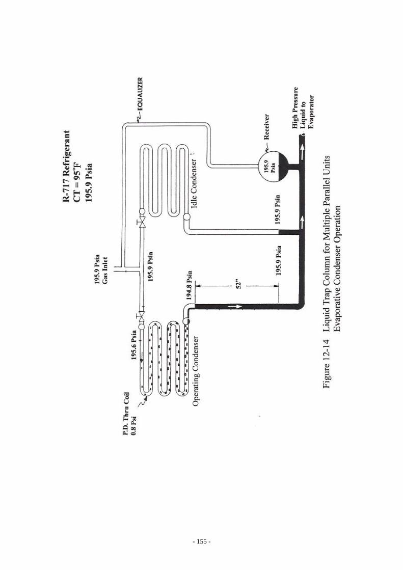
Liquid Trap Column for Multiple Parallel Units Operation: Liquid trap column is important for multiple coils or multiple evaporative condenser application when one or more condenser is to be shut off during operation. Figure 12-14 shows one condenser is operating while the other condenser is idling. The pressure at the outlet of the idle condenser is the same as inlet pressure. The liquid shall back up into and flooding the operating condenser coil if no trap liquid column is provided in this case. Assuming the refrigerant is Ammonia (R-717), CT is 95°F. The liquid column needed to off set the pressure unbalance under this operating condition is calculated as the following: Condensing Temperature: 95°F Condensing Pressure: 195.9 Psia Liquid Density: 36.68 Lbs/Ft3 Valve P.D.: 0.30 Psi Pressure after valve: 195.6 Psia Coil Pressure Drop: 0.8 Psi Liquid pressure leaving coil: 195.6 – 0.8 = 194.8 Psia Total pressure differential: 195.9 – 194.8 = 1.1 Psi Liquid Density (Lbs/Ft3) x Column (Ft) Pressure Diff. Psi = --------------------------------------------------- 144 36.68 (Lbs/Ft3) x Column (Ft) 1.1 Psi = -------------------------------------------- 144 1.1 x 144 Column (Ft) = --------------- = 4.32 Ft 36.68 = 52 Inches liquid column of R-717 From the above calculation, 52” liquid trap column is required to balance the pressure drop through the condenser coil and the valve for the R-717 at 95°F CT. The liquid column required for the various common refrigerants for each Psi PD are as the following: Refrigerant Liquid Trap Column ---------------- ------ ----------------------------------- R-717 Ammonia 48” for each Psi P.D. R-290 (Propane) 58” for each Psi P.D. R-1270 (Propylene) 57” for each Psi P.D. R-22 22” for each Psi P.D.
- 155 -

- 156 -
It is recommended to check with the evaporative condenser manufacturer to obtain the coil pressure drop for the coil or their recommendation as what is height of the liquid column trap should be provided for the parallel application. Evaporative Condensers in Parallel Operation: For the multiple evaporative condensers system, it becomes necessary to shut off one or more evaporative condenser from a multiple system to maintain sufficient condensing temperature and system pressure difference. Therefore, the piping hook-up and the liquid trap column are important for proper operation of the refrigeration system. Should the multiple evaporative condensers be used for a constant load or where the local wet bulb air temperature variation is not too much or all the condensers are expected to be operated all time even at partial load operation, liquid trap is not required under these circumstances. For multiple evaporative condenser units operation, the requisites for the arrangements are as the following: I) A receiver must be used. The receiver must be sized to have storage capacity
to hold the operating charge for all the conditions. II) An external equalizer line must be provided between the receiver and the gas
inlet line to the evaporative condensers. III) Enough vertical height liquid trap column shall be properly provided. IV) The vertical liquid drain lines from the evaporative condensers to receiver are
to be sized to have maximum velocity not more than 150 Ft/Min; the horizontal drain line is to be sized to have maximum velocity not more than 100 Ft/Min.
V) The equalizer line should be connected to the point where the pressure drop in
the gas inlet line to each evaporative condenser is approximately the same. VI) The shut off valves in the evaporative condenser liquid drain lines should be
located at the lowest elevation point as possible to minimize flash gas. VII) Normally, purge valve is to be located at the highest point of the liquid drain
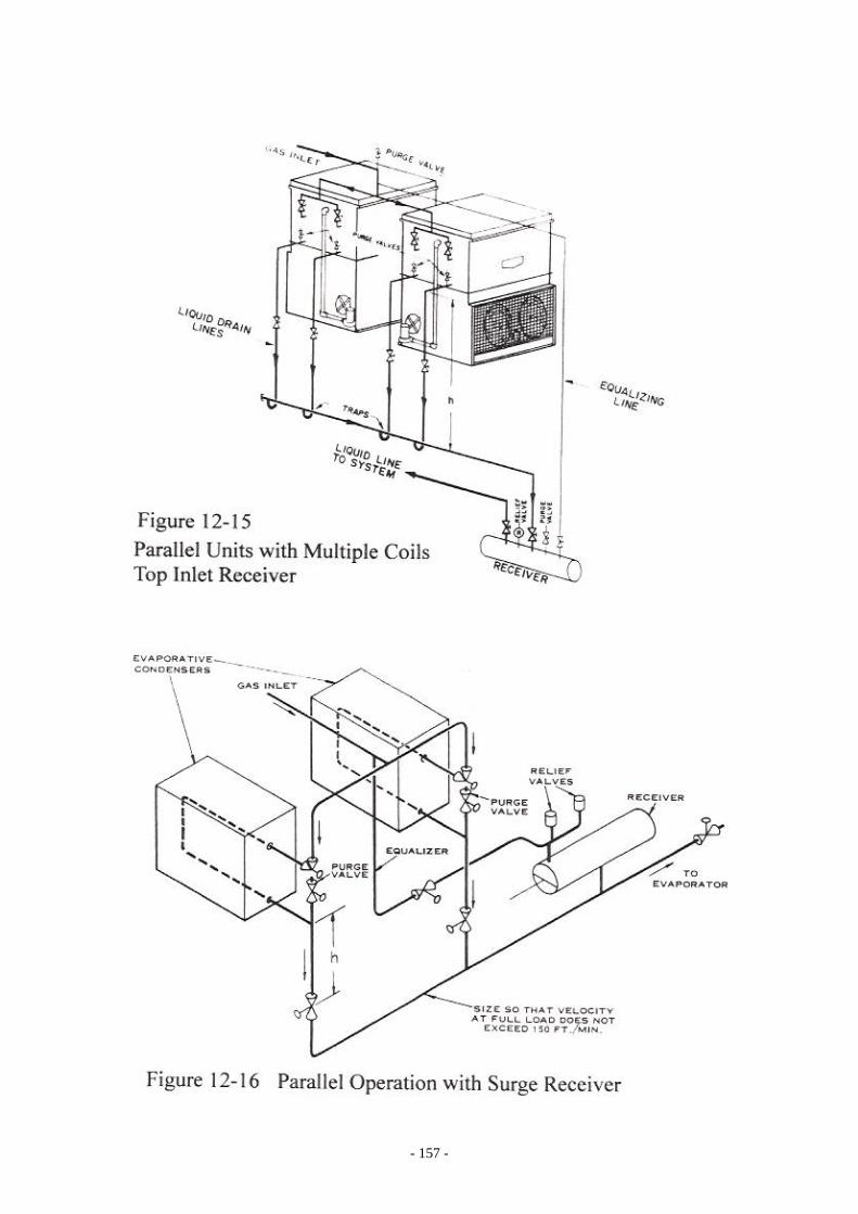
line. The followings are the suggested piping hook-up for various evaporative condensers connected in parallel operation: Figure 12-15 is the parallel condenser, each is having multiple coil circuits and with a storage liquid receiver. Figure 12-16 is the piping hookup for parallel evaporative condensers with a surge receiver.
- 157 -
- 158 -

- 159 -
- 160 -

- 161 -
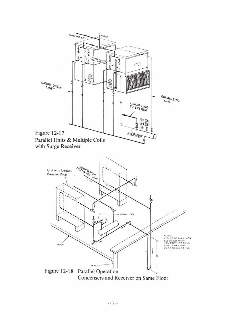
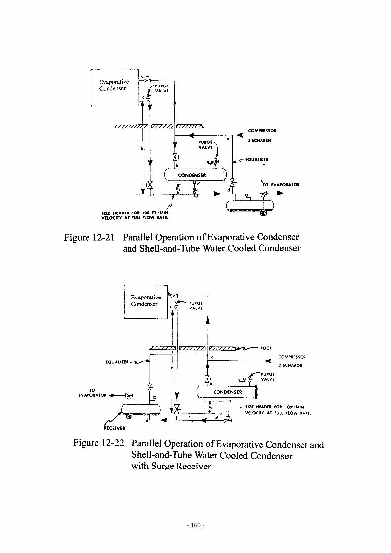
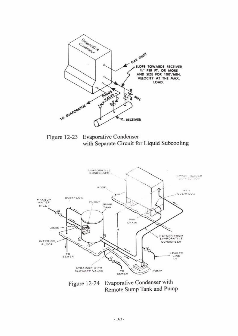
Figure 12-17 is the piping hookup for parallel operation and each unit is having multiple coils with a surge receiver. Figure 12-18 is the parallel condensers mounted on the same floor level. Figure 12-19 is the piping hookup for parallel operation but with mixed sizes of evaporative condensers. Figure 12-20 is the piping hookup suggestion for parallel evaporative condensers on the same floor when the trap liquid column is not available. In this case, dimension “A” is the elevation difference between evaporative condenser outlet and the top of the receiver; dimension “A” must be at least 20 inches. Dimension “B” should be as small as possible. It is suggested that both evaporative condensers are to be remain operated at the same time. Figure 12-21 shows an evaporative condenser and a shell-and-tube water cooled condenser are connected in parallel with top inlet storage receiver. H2 in this case is the height between the evaporative condenser and the operating liquid level in the receiver. This height is determined for the pressure drop along the circuit “a-b-c-d” including the pressure drop through the evaporative coil. H3 is the elevation between the bottom connection of the water cooled shell-and-tube condenser and the operating liquid level in the receiver; this height is determined by the pressure drop through the refrigerant circuit of “a-b’-c’-d”. Figure 12-22 shows the evaporative condenser and shell-and-tube water cooled condenser are connected in parallel with bottom inlet surge receiver. In this case, H2 is the height between the evaporative condenser and the operating liquid level in the receiver. This height is determined for the pressure drop along the circuit “a-b-c-d” including the pressure drop through the evaporative coil. H3 is the elevation between the bottom connection of the shell-and-tube condenser and the operating liquid level in the receiver; this height is determined by the pressure drop through the refrigerant circuit of “a-b’-c’-d”. The horizontal liquid drain line from the water cooled condenser to the receiver is to be sized for 100 Ft/Min velocity maximum at the design load. Liquid Subcooling: Certain degree of liquid subcooling can be obtained by the evaporative condenser. However, the subcooling should be arranged in a separate circuit in the evaporative condenser as shown in the Figure 12-23. The liquid from receiver for the subcooling should be taken out at the downstream of the receiver to minimize the chance that vapor mixes with liquid at this point. Winter and Low Ambient Operation: For industrial refrigeration installations, the refrigeration system is required to be operated year round. Therefore, it is necessary to take provisions of maintaining a minimum required condensing pressure for the refrigeration system and also to prevent the water being freeze up in the evaporative condenser.

- 162 -
One of the better control methods for winter operation for evaporative condenser is to have automatic damper control of air flow for the evaporative condenser instead of dry coil operation. Dry coil operation needs change over and the method of control is not entirely satisfactory. In order to prevent the water in the evaporative condenser freeze up during the system during shut down is to have a remote water recirculation system consists of sump tank and a pump to be located indoor as shown in Figure 12-24. Data required for evaporative condenser selection and inquiry:
Heat rejection, Btu/Hr. Condensing temperature. Refrigerant. Ambient wetbulb air temperature, °F. Fan type, vane axial or centrifugal. Induced draft or blow thru arrangement. Subcooling coil, if required. Special coating of additional corrosion protection. Head control requirement. Power supply, type of motor and electrical code requirement.
- 163 -
- 164 -
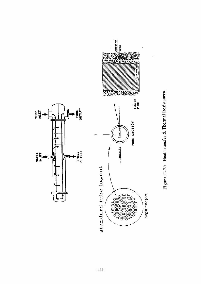
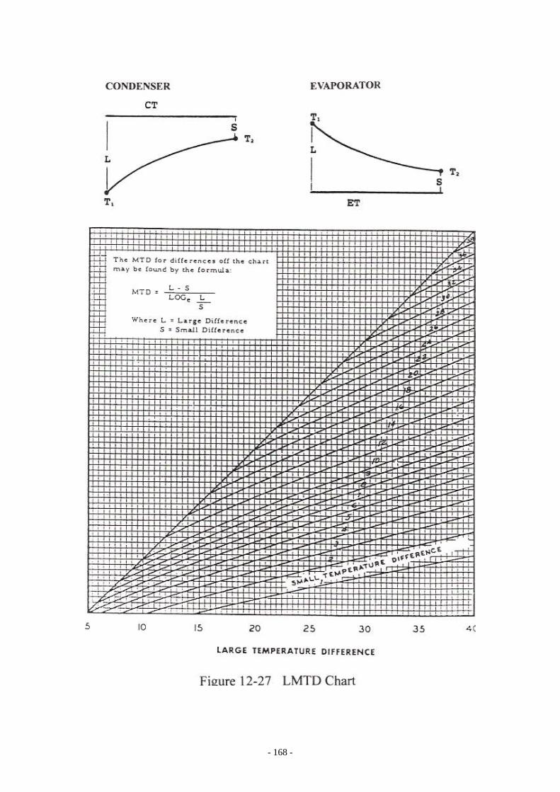
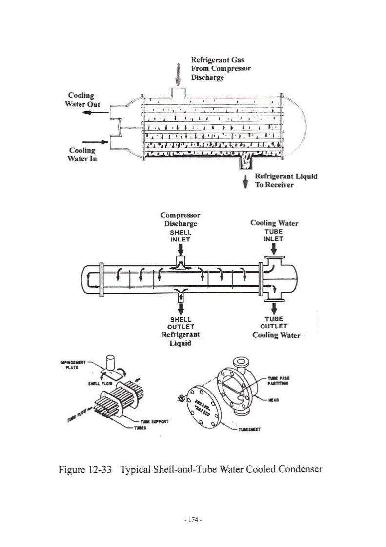
Shell-and-Tube Heat Exchangers Various heat exchangers for refrigeration application under the category of shell-and-tube are as the following: (I) Water Cooled Condenser. (Figure 12-33) (II) Evaporators: Flooded Type: Half Bundle type. (Figure 12-39) Full Bundle with Surge Drum. (Figure 12-40) Dry Expansion (DX). (Figure 12-42) Thermosyphone. (Figure 12-43) Spray Evaporator. (Figure 12-44) Overfeed Evaporator. (Figure 12-45) Kettle Type Evaporator. (Figure 12-46) Most the shell-and-tube heat exchangers for refrigeration application are horizontal with fixed tube sheet design that includes both condenser and evaporators. The efficiency of a vertical heat exchanger is not as good as the horizontal design; floating tube sheets design heat exchanger is not warranted for refrigeration system. The heat exchangers with U-tubes and/or floating tube sheet design are mainly used for evaporator duty and mostly are provided by the hydrocarbon processing industries users, not by refrigeration system providers. Small Difference and LMTD: The heat transfer formula for condenser or evaporator is as the following: Q = U x Ao x LMTD Q = Heat transferred, Btu/Hr. U = Overall heat transfer coefficient, Btu/Hr- Ft2-℉. Ao = Total effective outside tube surface, Ft2. L - S LMTD = ----------------------------- L LOGe { -------- } S The heat transmission and the thermal resistances through the tube are shown in Figure 12-25. Figure 12-26 shows the heat transmission resistances and the temperature gradients for the tube wall and each layer of film through the tube section from t1 to t7. Small difference value is the difference between CT and the leaving cooling water or the
- 165 -

- 166 -

- 167 -
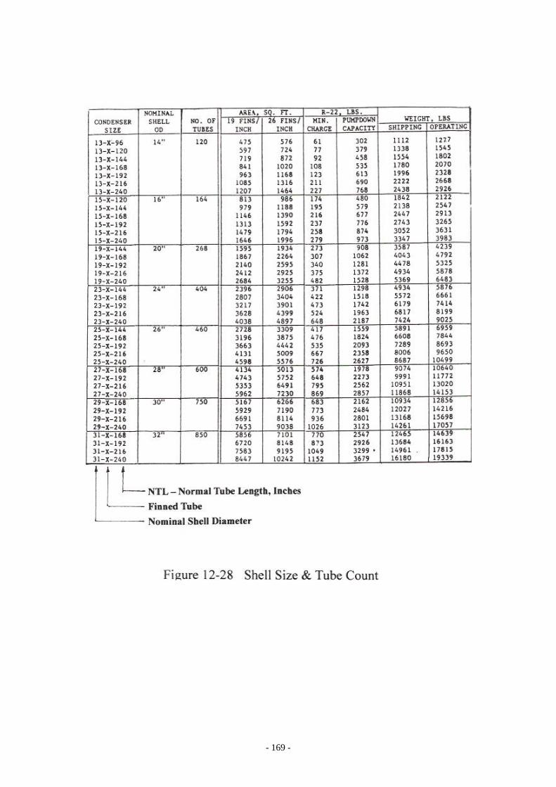
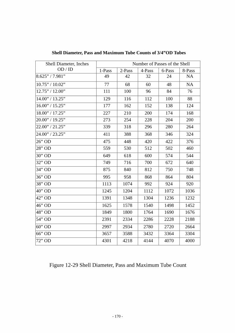
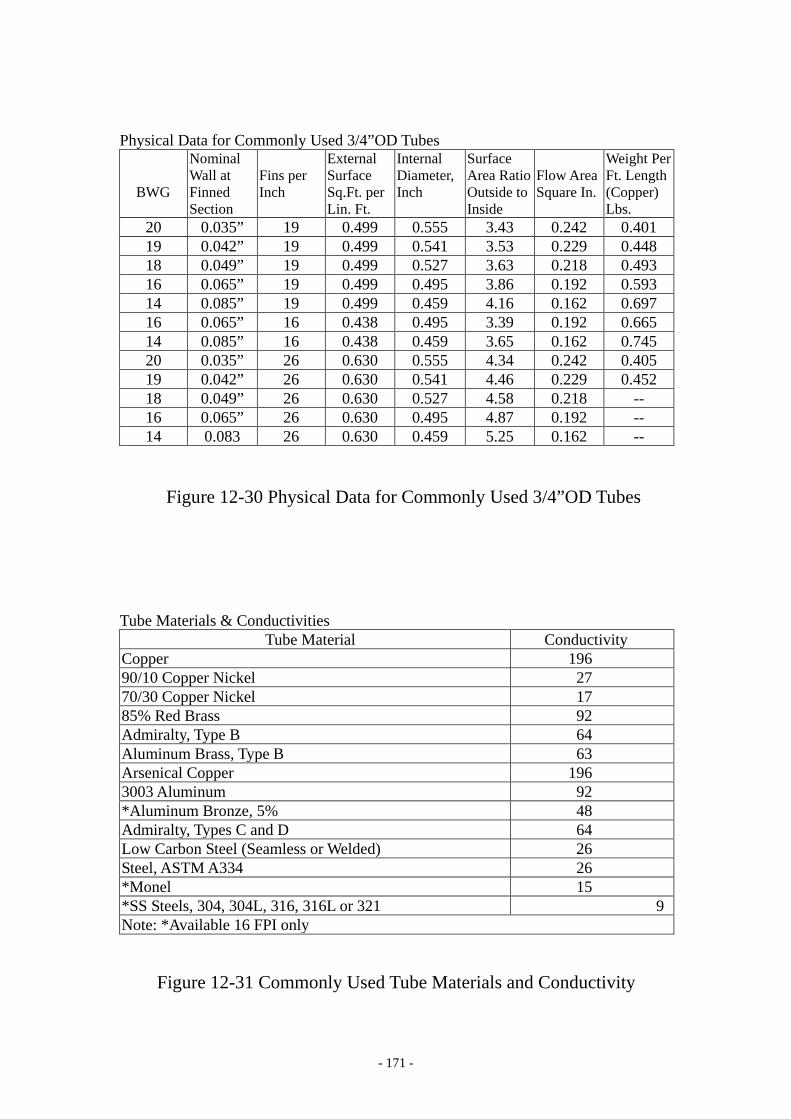
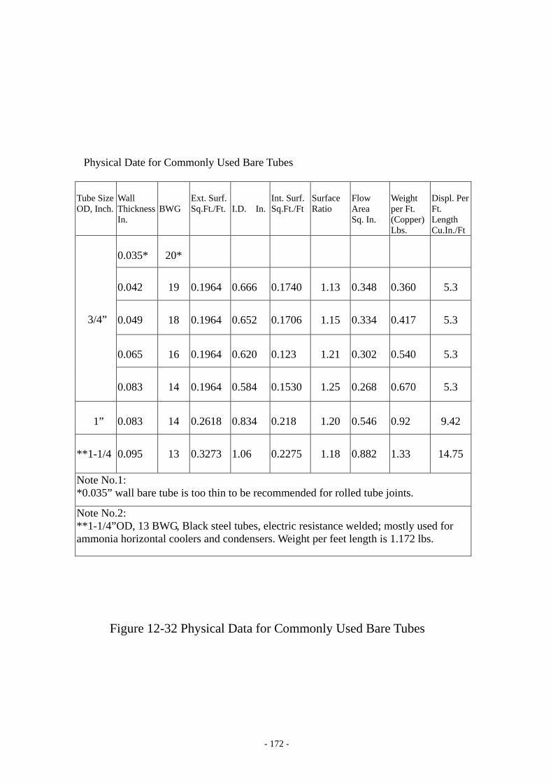
difference between the leaving fluid temperature and the ET as shown in Figure 12-27. Some of the condenser or cooler performance curves are expressed in small difference instead of LMTD. Shell Diameter and Tubes Count: Figure 12-28 shows the optimum total possible tubes insert for a give shell diameter, the general heat exchanger data and the total external surface for the heat exchanger for given size of the heat exchanger. Figure 12-29 is the table for various shell diameter and number of tube counts for various pass arrangement for the heat exchanger. All the data are based on 3/4” OD tubes on 15/16” Triangular Pitch for both condenser and evaporator. For example: For a shell diameter of 24”OD, 2-Pass arrangement, full bundle flooded evaporator, maximum tubes count is 388. Figure 12-30 shows the physical data for various commonly used 3/4" OD finned tubes. Figure 12-31 is the commonly used tube material and the corresponding thermal conductivity, Btu/ Ft2-℉-Hr/Ft at 60℉. Figure 12-32 is the physical data for various commonly used bare tubes. Code and Standard Compliance: The manufacturing and the construction of shell-and-tube heat exchanger is to confirm with ASME code Section VIII for Unfired Pressure Vessels, see Chapter 13 for further details. The water heads for the shell-and-tube heat exchanger under ASME code can be either water channel or regular water box or marine water box. The definition of “marine” water box is that the water box for the heat exchanger shall be constructed in such way without disturbing the water piping connections while cleaning tubes for the heat exchanger.
- 168 -
- 169 -
- 170 -
Shell Diameter, Pass and Maximum Tube Counts of 3/4”OD Tubes
Shell Diameter, Inches OD / ID
Number of Passes of the Shell 1-Pass 2-Pass 4-Pass 6-Pass 8-Pass
8.625” / 7.981” 49 42 32 24 NA
10.75” / 10.02” 77 68 60 48 NA 12.75” / 12.00” 111 100 96 84 76 14.00” / 13.25” 129 116 112 100 88 16.00” / 15.25” 177 162 152 138 124 18.00” / 17.25” 227 210 200 174 168 20.00” / 19.25” 273 254 228 204 200 22.00” / 21.25” 339 318 296 280 264 24.00” / 23.25” 411 388 368 346 324 26” OD 475 448 420 422 376 28” OD 559 530 512 502 460 30” OD 649 618 600 574 544 32” OD 749 716 700 672 640 34” OD 875 840 812 750 748 36” OD 995 958 868 864 804 38” OD 1113 1074 992 924 920 40” OD 1245 1204 1112 1072 1036 42” OD 1391 1348 1304 1236 1232 46” OD 1625 1578 1540 1498 1452 48” OD 1849 1800 1764 1690 1676 54” OD 2391 2334 2286 2228 2188 60” OD 2997 2934 2780 2720 2664 66” OD 3657 3588 3432 3364 3304 72” OD 4301 4218 4144 4070 4000 Figure 12-29 Shell Diameter, Pass and Maximum Tube Count
- 171 -
Physical Data for Commonly Used 3/4”OD Tubes
BWG
Nominal Wall at Finned Section
Fins per Inch
External Surface Sq.Ft. per Lin. Ft.
Internal Diameter, Inch
Surface Area Ratio Outside to Inside
Flow Area Square In.
Weight Per Ft. Length (Copper) Lbs.
20 0.035” 19 0.499 0.555 3.43 0.242 0.401 19 0.042” 19 0.499 0.541 3.53 0.229 0.448 18 0.049” 19 0.499 0.527 3.63 0.218 0.493 16 0.065” 19 0.499 0.495 3.86 0.192 0.593 14 0.085” 19 0.499 0.459 4.16 0.162 0.697 16 0.065” 16 0.438 0.495 3.39 0.192 0.665 14 0.085” 16 0.438 0.459 3.65 0.162 0.745 20 0.035” 26 0.630 0.555 4.34 0.242 0.405 19 0.042” 26 0.630 0.541 4.46 0.229 0.452 18 0.049” 26 0.630 0.527 4.58 0.218 -- 16 0.065” 26 0.630 0.495 4.87 0.192 -- 14 0.083 26 0.630 0.459 5.25 0.162 --
Figure 12-30 Physical Data for Commonly Used 3/4”OD Tubes Tube Materials & Conductivities
Tube Material Conductivity Copper 196 90/10 Copper Nickel 27 70/30 Copper Nickel 17 85% Red Brass 92 Admiralty, Type B 64 Aluminum Brass, Type B 63 Arsenical Copper 196 3003 Aluminum 92 *Aluminum Bronze, 5% 48 Admiralty, Types C and D 64 Low Carbon Steel (Seamless or Welded) 26 Steel, ASTM A334 26 *Monel 15 *SS Steels, 304, 304L, 316, 316L or 321 9 Note: *Available 16 FPI only
Figure 12-31 Commonly Used Tube Materials and Conductivity
- 172 -
Physical Date for Commonly Used Bare Tubes
Tube Size OD, Inch.
Wall Thickness In.
BWG
Ext. Surf. Sq.Ft./Ft.
I.D. In.
Int. Surf. Sq.Ft./Ft
Surface Ratio
Flow Area Sq. In.
Weight per Ft. (Copper) Lbs.
Displ. Per Ft. Length Cu.In./Ft
3/4”
0.035*
20*
0.042
19
0.1964
0.666
0.1740
1.13
0.348
0.360
5.3
0.049
18
0.1964
0.652
0.1706
1.15
0.334
0.417
5.3
0.065
16
0.1964
0.620
0.123
1.21
0.302
0.540
5.3
0.083
14
0.1964
0.584
0.1530
1.25
0.268
0.670
5.3
1”
0.083
14
0.2618
0.834
0.218
1.20
0.546
0.92
9.42
**1-1/4
0.095
13
0.3273
1.06
0.2275
1.18
0.882
1.33
14.75
Note No.1: *0.035” wall bare tube is too thin to be recommended for rolled tube joints.
Note No.2: **1-1/4”OD, 13 BWG, Black steel tubes, electric resistance welded; mostly used for ammonia horizontal coolers and condensers. Weight per feet length is 1.172 lbs.
Figure 12-32 Physical Data for Commonly Used Bare Tubes

- 173 -
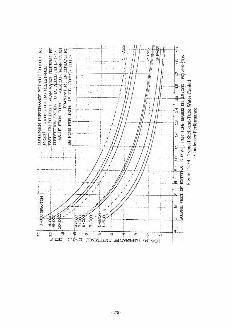
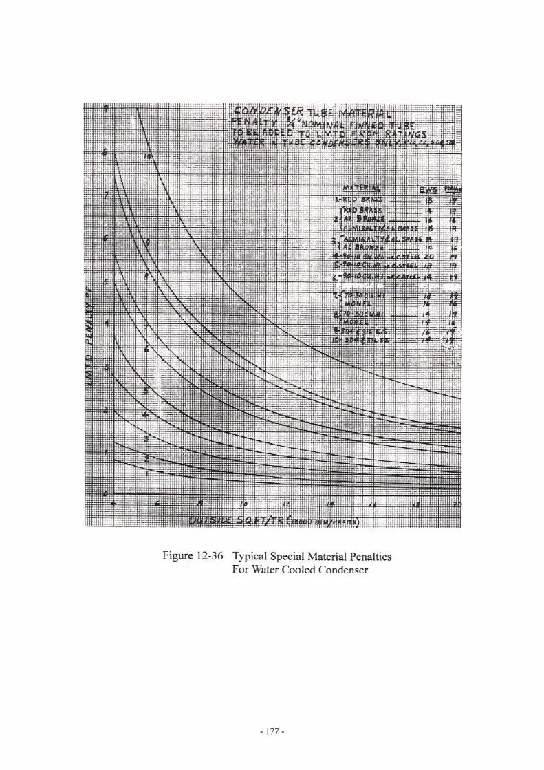
Water Cooled Condenser Figure 12-33 shows the typical horizontal design shell-and-tube water cooled condenser. Cooling tower water is used for most shell-and-tube condenser installations. Besides of cooling tower, the cooling medium for condenser can be river water, well water or sea water. Water softening is commonly used these days for cooling tower to minimize the fouling build-up in the tubes. The most commonly used tube material for the condenser is copper. The condenser tube material should be changed to other corrosion resistance material if sea water is used. Some cases, the river or well water is also salty and corrosive, special tube material such as 90/10 Cupro Nickel or 70/30 Curpo Nickel should be used instead of copper for these application. Titanium tubes and tube sheet design condenser is the best for corrosion resistance, however it is the most expensive. Cooling tower water is usually designed to have leaving water temperature 7 to 10℉ above the design outdoor ambient wet bulb air temperature. The water range for condenser is usually about 10 to 15℉. Water Cooled Condenser Performance: δT = CT - Tw δT = Small Difference, ℉ CT = Condensing Temperature, ℉ Tw = Leaving Condenser Water Temperature, ℉ Therefore: CT = δT + Tw Figure 12-34 is a typical water cooled condenser performance curve. Figure 12-35 is a diagram to show the impact of higher fouling factor for condenser rather than the normal allowance of 0.0005 Ft2- Hr-℉/Btu. Figure 12-36 is the typical curve to show the impact of using other material for the condenser instead of copper. Those correction factors are in approximate LMTD to be added to the overall LMTD of the heat transfer for the condenser. Cooling fluid flow calculation: Btu/Hr. GPM = -----------------------------------------------------
499.8 x S.G. x Cp x (T2 - T1)
Btu/Hr = Heat rejection GPM = Cooling fluid flow, Gal/Min
- 174 -
- 175 -

- 176 -
- 177 -
- 178 -
S.G.. = Specific Gravity of fluid at average temperature
Cp = Specific Heat of fluid at average temperature T2 - T1 = Range, fluid temperature difference, °F
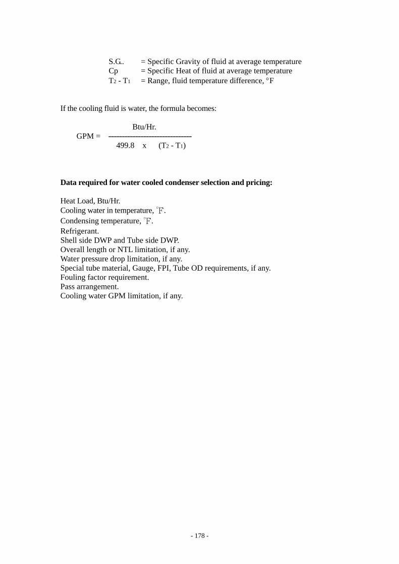
If the cooling fluid is water, the formula becomes: Btu/Hr. GPM = -------------------------------
499.8 x (T2 - T1) Data required for water cooled condenser selection and pricing: Heat Load, Btu/Hr. Cooling water in temperature, ℉. Condensing temperature, ℉. Refrigerant. Shell side DWP and Tube side DWP. Overall length or NTL limitation, if any. Water pressure drop limitation, if any. Special tube material, Gauge, FPI, Tube OD requirements, if any. Fouling factor requirement. Pass arrangement. Cooling water GPM limitation, if any.
- 179 -
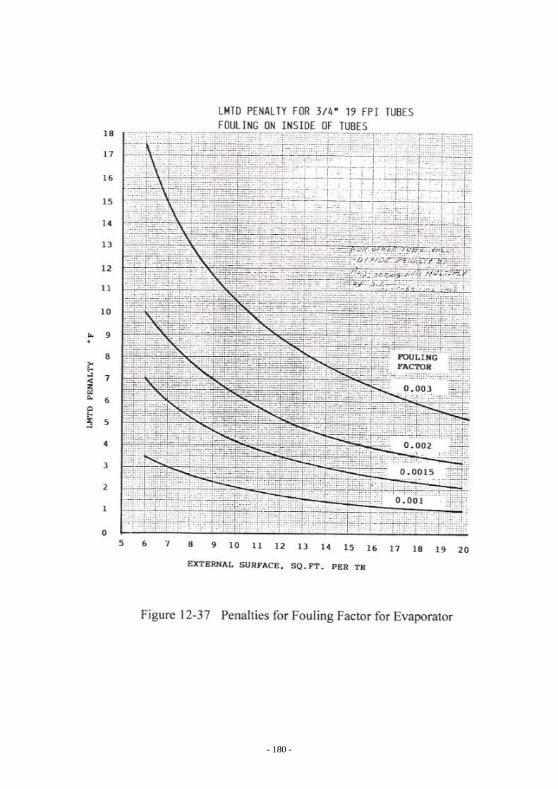
Evaporator All the heat exchangers are to be selected by the heat exchanger manufacturer because the type of heat exchanger, NTL length, shell diameter, tube type, tube size, tube material and heat transfer coefficients vary widely depending on the brine or product and temperatures handled. Evaporator Performance: δT = Tw – ET δT = Small Difference, ℉ ET = Evaporative Temperature, ℉ Tw = Leaving Chilled Water Temperature, ℉ Therefore: ET = Tw - δT Figure 12-37 shows the impact on various fouling factor for evaporator. The Figure 12-38 is the impact on evaporator if other tube material is used instead of copper tubes. These penalties for higher fouling factor or for special tube material are to be included in the value of δT. Calculation for brine cooling is more complicated than for water because of the specific gravity, viscosity and thermal conductivity and etc. vary widely. Viscosity of the brine impacts greatly on the size of the heat exchanger. More tube heat transfer surface Ft2/TR is needed for the application if the brine is having higher viscosity. As a rough guide and a rule of thumb, if a flooded evaporator is with 20 BWG 19 FPI 3/4” tubes, the relationships between Ft2/TR and the viscosity of the brine are as the following:
Ft2/TR Brine Viscosity 8 Square Ft. per TR 2 to 3 CP 10 Square Ft. per TR 3 to 5 CP 14 Square Ft. per TR 5 to 8 CP 18 Square Ft. per TR 9 to 12 CP
A different type of evaporator should be considered instead of flooded evaporator if the brine viscosity is above 12 CP. Fluid or Brine flow for evaporator: TR x 24 GPM = ----------------------------------- S.G. x Cp x (T2 - T1) OR
Btu/Hr. = GPM x 499.8 x S.G. x Cp x (T2 - T1)
- 180 -

- 181 -
- 182 -
TR = Tons of refrigeration GPM = Fluid flow, Gal/Min
S.G. = Specific Gravity of fluid at average temperature Cp = Specific Heat of fluid at average temperature T2 - T1 = Range, Temperature Difference, °F
Submerge Penalty: For low temperature application, the density of the refrigerant liquid inside the evaporator increases rapidly as the evaporative temperature getting lower, the static head is increasingly greater accordingly. The evaporative temperature is to be lowered to offset this submerge penalty. The larger the shell diameter and lower the ET, more submerge penalty should be allowed. The degree of submergence effect also greatly depends on what refrigerant is used. Data Required for Evaporator Selection and Pricing: Refrigeration Load, TR or Btu/Hr. In and out temperatures, °F. Refrigerant. Shell side DWP and Tube side DWP. Evaporative Temperature, °F. Pass arrangement. Fouling factor. Pressure drop allowed, if any. Special tube material, if any. Special requirements for tube OD, FPI, NTL, if any. Additional information required if the cooling fluid is common brine instead of water: Name of the brine, WT% brine concentration, if specified. Additional information required if the medium is special fluid or special brine: Name of the brine for fluid. Specific heat at the average temperature. Specific gravity at the average temperature. Thermal Conductivity at the average temperature. Viscosity at four temperature points: At the brine average temperature. At the leaving brine temperature. At 10°F below brine leaving temperature. At 15°F below brine leaving temperature. Additional information required if the application is for gas condensation: Name of the gas. Mole fraction of each components of the gas mixture. Half Bundle Flooded Evaporator: Figure 12-39 is the half bundle or partial bundle evaporator design. This heat exchanger is one cylindrical shell. Lower half of the bundle is for tubes insert and the integral upper

- 183 -
- 184 -
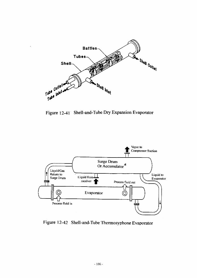
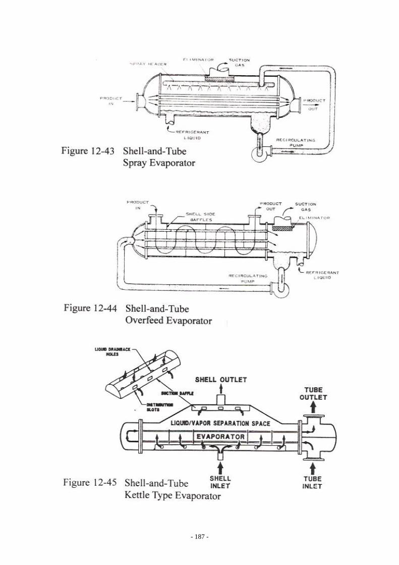
half space is for gas/liquid separation. The advantage of using this half bundle design is for installation where ceiling height is limited. The disadvantages are bigger shell diameter is required; might require higher submerging penalty if the ET is low and operating refrigerant charge is higher. Full Bundle Flooded Evaporator: Figure 12-40 is the full bundle shell-and-tube flooded evaporator. This heat exchanger consists of two shells. The lower shell is the evaporator which contains full bundle of tubes insert. The upper shell is the surge drum or the accumulator which provides the space for gas and liquid separation. These two shells are connected by the risers as shown. Dry Expansion Evaporator: Figure 12-41 is the DX evaporator. It is a low cost heat exchanger and it simplifies the refrigeration system design. DX system is basically used for small capacity installation. Thermosypone Evaporator: Figure 12-42 is a typical thermosyphone evaporator. The thermosyphone evaporator is a shell-and-tube heat exchanger coupled with a surge drum or accumulator. The brine or fluid flows through the shell side and the refrigerant is through the tube side. This heat exchanger is designed to cool high viscous fluid or brine. The refrigerant liquid is supplied to the thermosyphone evaporator from the surge drum on top of the evaporator by gravity force. Portion of the liquid is vaporized to cool the fluid in the heat exchanger; the bubbling mixture of liquid/vapor is circulated back to the surge drum. The refrigerant liquid from high side receiver is supplied to the surge drum through an expansion device such as liquid level control valve. Gas is returned to compressor suction from the surge drum. The surge drum must be located at a certain height above the evaporator in order to generate the thermosyphone effect. Spray Evaporator: Figure 12-43 shows the spray type shell-and-tube evaporator. This type of evaporator is used to minimize the refrigerant charge and also is used for very low temperature refrigeration to eliminate the submerge penalty in the evaporator. Liquid is pump recirculated. The liquid refrigerant charge is limited. The shell should be sized to provide gas/liquid separation or moisture eliminator should be provided to prevent liquid carry over back to compressor suction. Overfeed Evaporator: Figure 12-44 is the liquid overfeed type evaporator. The refrigerant liquid is forced feed through the tube. This heat exchanger is designed to cool high viscous product or brine because the product or brine is through the shell, not through the tubes. The application of this evaporator is the same as the thermosyphone evaporator except that the liquid is forced fed by a pump instead of by gravity fed, therefore, no height limitation is needed between the separation compartment and the evaporator.

- 185 -
- 186 -
- 187 -

- 188 -
Kettle Type Evaporator: Figure 12-45 is the Kettle type evaporator. This type of evaporator is usually used by oil refinery, petrochemical and hydrocarbon processing industries. It only used for very special application and it usually provided by the user.