Embed Size (px)
Citation preview

Chapter 30 – Inductance
- Mutual Inductance
- Self-Inductance and Inductors
- Magnetic-Field Energy
- The R-L Circuit
- The L-C Circuit
- The L-R-C Series Circuit
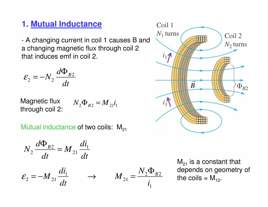
1. Mutual Inductance
- A changing current in coil 1 causes B and a changing magnetic flux through coil 2 that induces emf in coil 2.
dt
dN B2
22
Φ−=ε
12122iMN B =Φ
1
22
21
1
212i
NM
dt
diM BΦ
=→−=ε
dt
diM
dt
dN B 1
21
2
2=
Φ
Magnetic fluxthrough coil 2:
Mutual inductance of two coils: M21
M21 is a constant that depends on geometry of the coils = M12.
dt
diM
dt
diM
2
1
1
2
−=
−=
ε
ε
2
11
1
22
i
N
i
NM BB Φ
=Φ
=
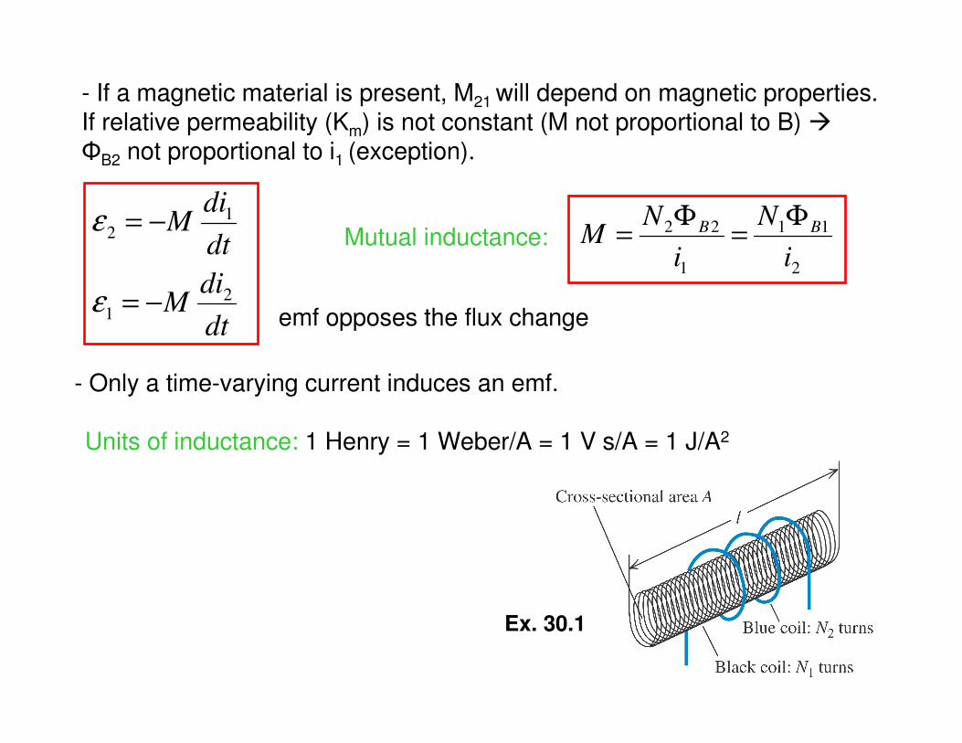
- If a magnetic material is present, M21 will depend on magnetic properties. If relative permeability (Km) is not constant (M not proportional to B) �ΦB2 not proportional to i1 (exception).
Ex. 30.1
Mutual inductance:
emf opposes the flux change
- Only a time-varying current induces an emf.
Units of inductance: 1 Henry = 1 Weber/A = 1 V s/A = 1 J/A2
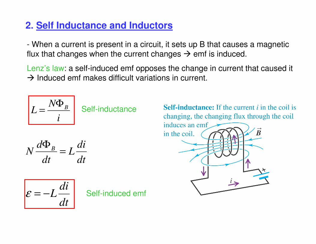
2. Self Inductance and Inductors
i
NL BΦ
=
dt
diL
dt
dN B =
Φ
dt
diL−=ε
- When a current is present in a circuit, it sets up B that causes a magnetic flux that changes when the current changes � emf is induced.
Lenz’s law: a self-induced emf opposes the change in current that caused it � Induced emf makes difficult variations in current.
Self-inductance
Self-induced emf
dt
diLldEn −=∫
��
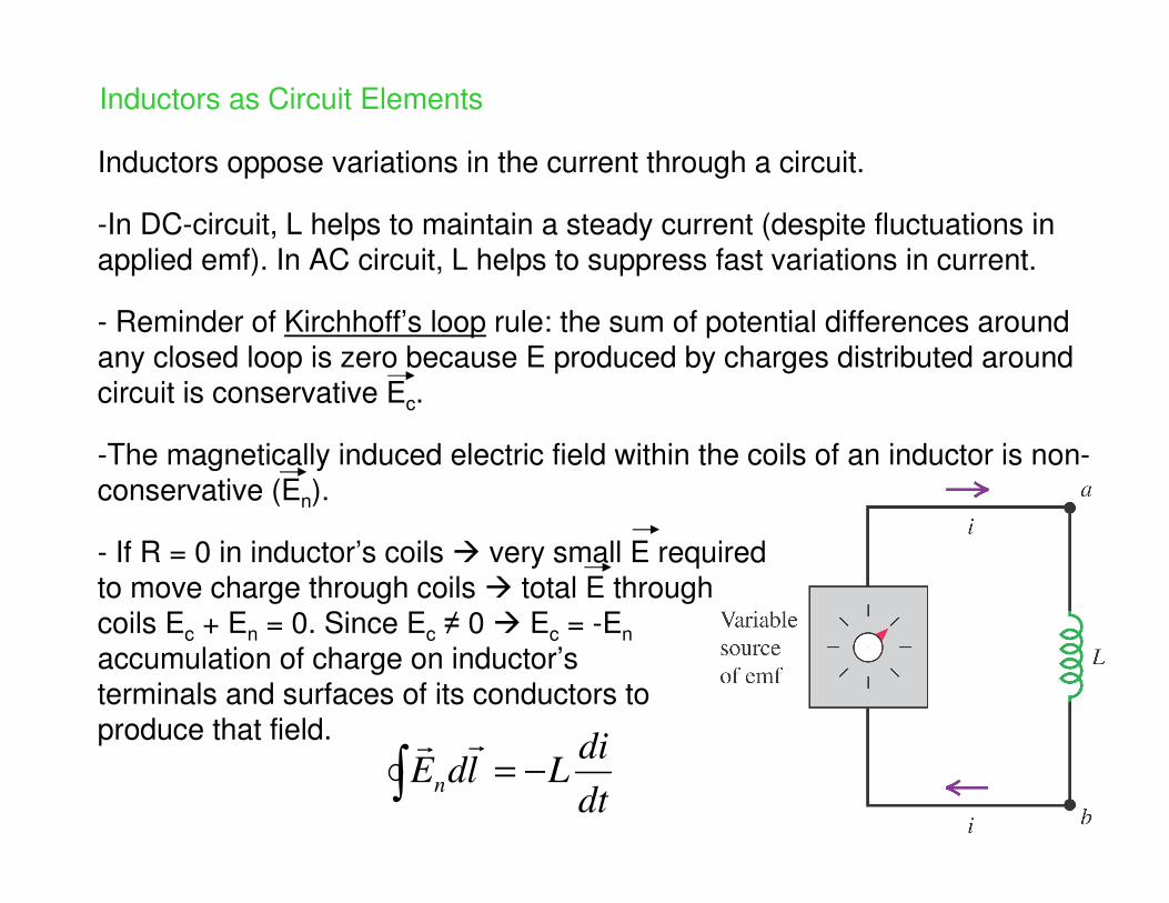
Inductors as Circuit Elements
Inductors oppose variations in the current through a circuit.
-In DC-circuit, L helps to maintain a steady current (despite fluctuations in applied emf). In AC circuit, L helps to suppress fast variations in current.
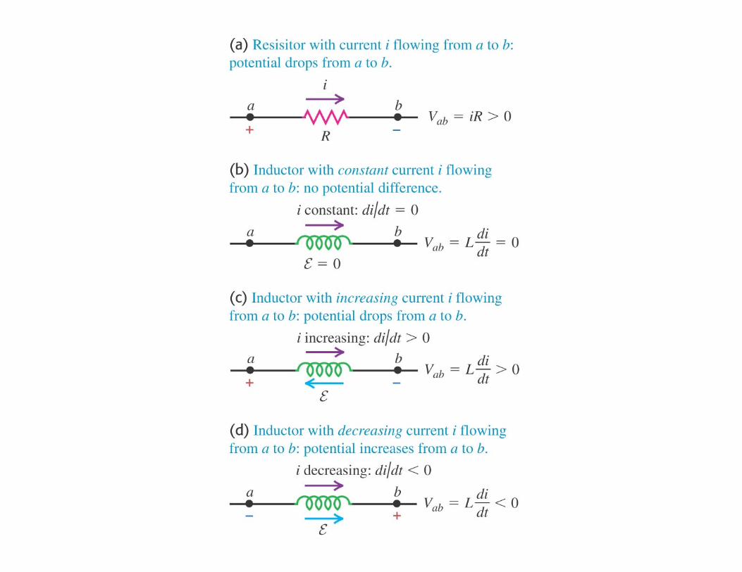
- Reminder of Kirchhoff’s loop rule: the sum of potential differences around any closed loop is zero because E produced by charges distributed around circuit is conservative Ec.
-The magnetically induced electric field within the coils of an inductor is non-conservative (En).
- If R = 0 in inductor’s coils � very small E requiredto move charge through coils � total E through coils Ec + En = 0. Since Ec ≠ 0 � Ec = -En
accumulation of charge on inductor’s terminals and surfaces of its conductors to produce that field.
0=+ nc EE��
dt
diLVVV baab =−=
dt
diLldE
dt
diLldE
b
a
c
b
a
n
=⋅
−=⋅
∫
∫
��
��
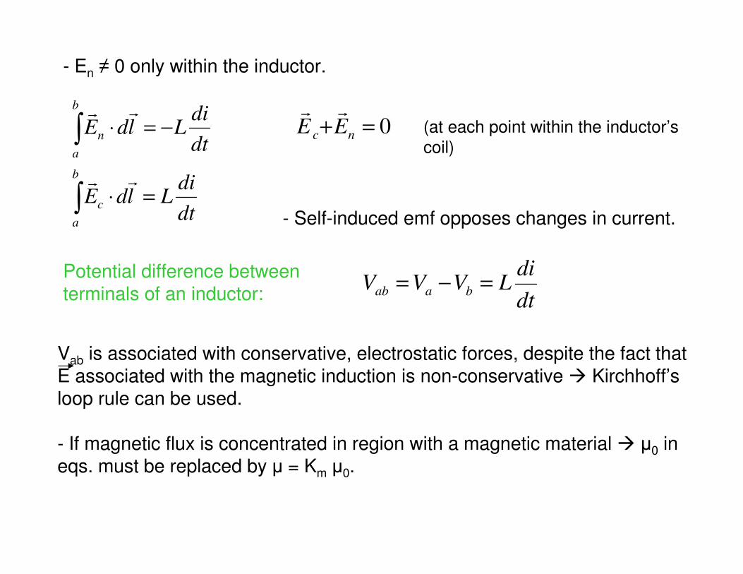
- En ≠ 0 only within the inductor.
Potential difference betweenterminals of an inductor:
- Self-induced emf opposes changes in current.
(at each point within the inductor’s
coil)
Vab is associated with conservative, electrostatic forces, despite the fact that E associated with the magnetic induction is non-conservative � Kirchhoff’s loop rule can be used.
- If magnetic flux is concentrated in region with a magnetic material � µ0 in eqs. must be replaced by µ = Km µ0.
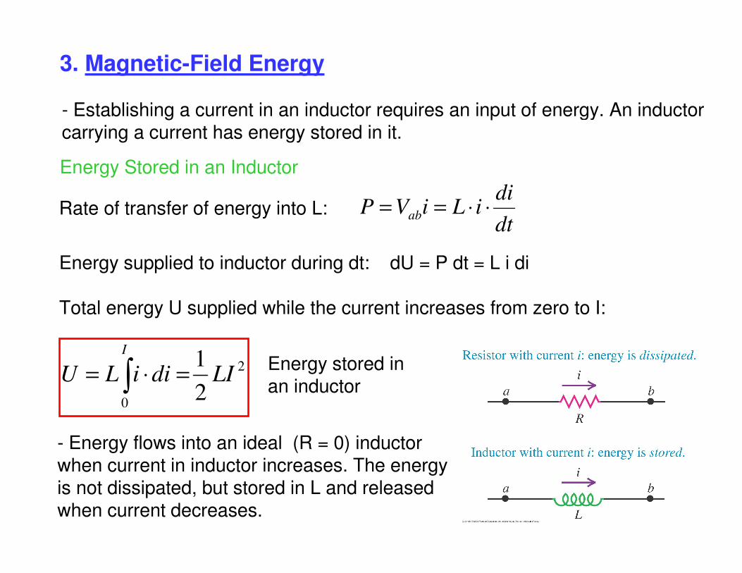
3. Magnetic-Field Energy
Energy Stored in an Inductor
dt
diiLiVP ab ⋅⋅==
2
02
1LIdiiLU
I
∫ =⋅=
- Establishing a current in an inductor requires an input of energy. An inductor carrying a current has energy stored in it.
Rate of transfer of energy into L:
Total energy U supplied while the current increases from zero to I:
Energy supplied to inductor during dt: dU = P dt = L i di
Energy stored in an inductor
- Energy flows into an ideal (R = 0) inductorwhen current in inductor increases. The energyis not dissipated, but stored in L and releasedwhen current decreases.
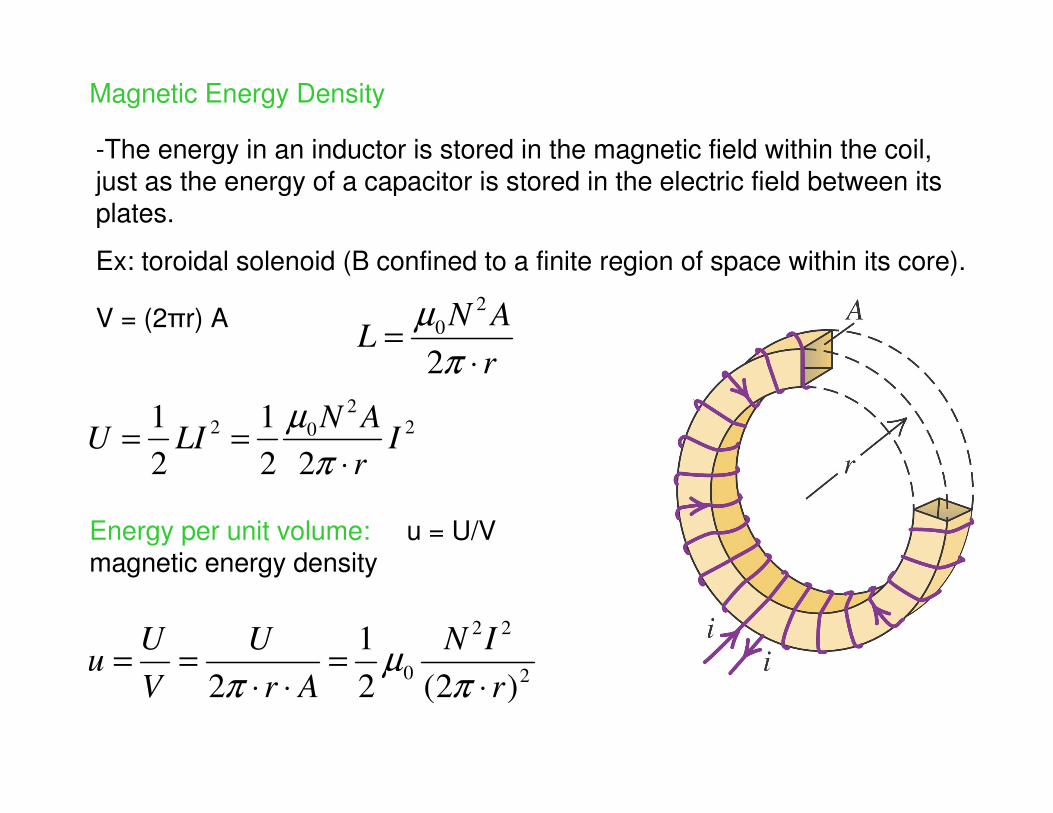
Magnetic Energy Density
r
ANL
⋅=
π
µ
2
2
0
2
22
0)2(2
1
2 r
IN
Ar
U
V
Uu
⋅=
⋅⋅==
πµ
π
2
2
02
22
1
2
1I
r
ANLIU
⋅==
π
µ
-The energy in an inductor is stored in the magnetic field within the coil, just as the energy of a capacitor is stored in the electric field between its plates.
Ex: toroidal solenoid (B confined to a finite region of space within its core).
V = (2πr) A
Energy per unit volume: u = U/Vmagnetic energy density
µ
µ
2
2
2
0
2
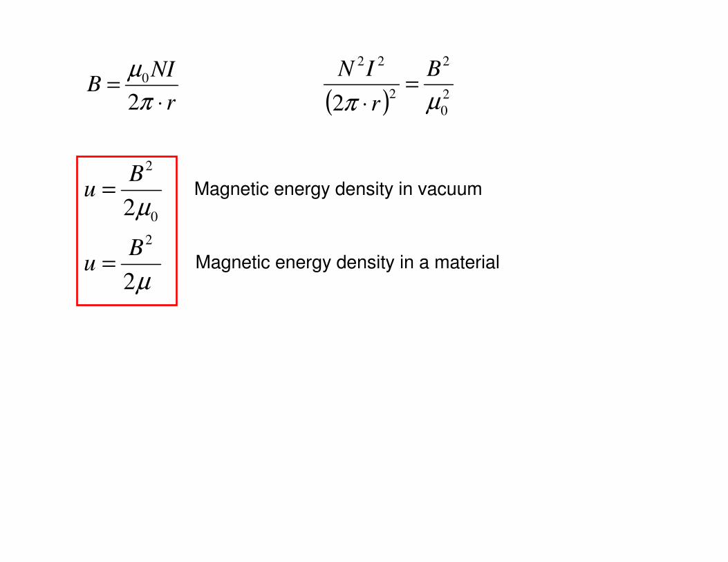
Bu
Bu
=
=
( ) 2
0
2
2
22
2 µπ
B
r
IN=
⋅r
NIB
⋅=
π
µ
2
0
Magnetic energy density in vacuum
Magnetic energy density in a material
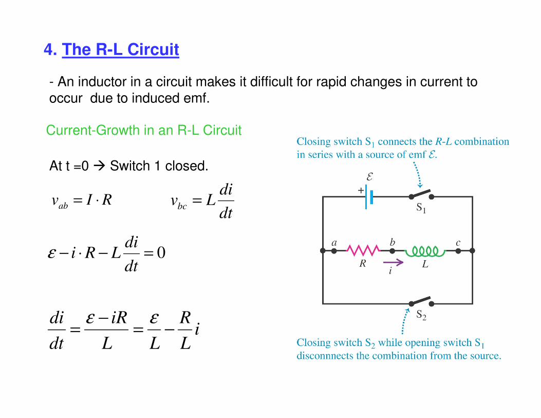
4. The R-L Circuit
Current-Growth in an R-L Circuit
RIvab ⋅=dt
diLvbc =
0=−⋅−dt
diLRiε
iL
R
LL
iR
dt
di−=
−=
εε
- An inductor in a circuit makes it difficult for rapid changes in current to occur due to induced emf.
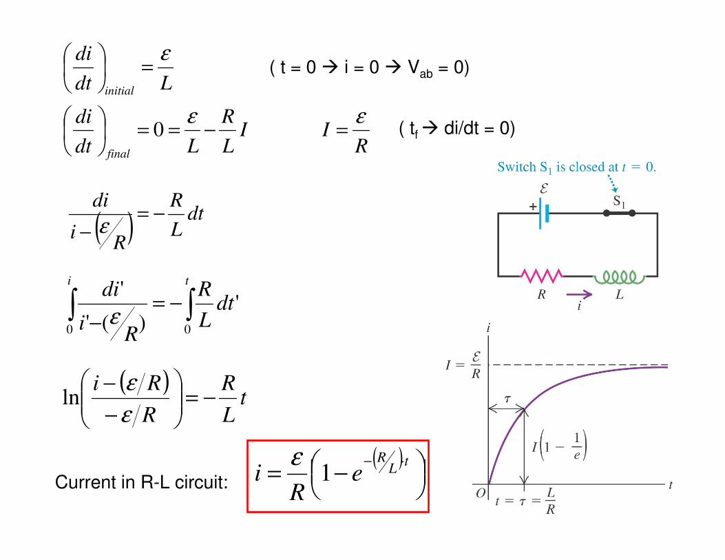
At t =0 � Switch 1 closed.
RII
L
R
Ldt
di
Ldt
di
final
initial
εε
ε
=−==
=
0
( )dt
L
R
Ri
di−=
− ε
∫ ∫−=−
i t
dtL
R
Ri
di
0 0
')('
'
ε
( t = 0 � i = 0 � Vab = 0)
( tf � di/dt = 0)
( )t
L
R
R
Ri−=
−
−
ε
εln
( )
−=
⋅− tL
R
eR
i 1ε
Current in R-L circuit:
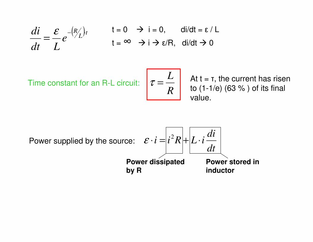
R
L=τ
( ) tL
R
eLdt
di ⋅−=
ε
dt
diiLRii ⋅+=⋅ 2ε
t = 0 � i = 0, di/dt = ε / L
t = ∞ � i � ε/R, di/dt � 0
Time constant for an R-L circuit: At t = τ, the current has risento (1-1/e) (63 % ) of its final value.
Power supplied by the source:
Power dissipated
by R
Power stored in
inductor
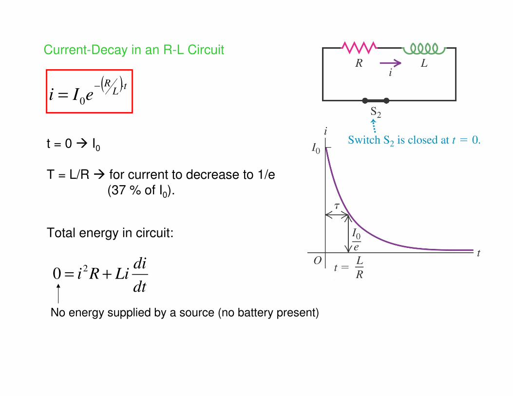
Current-Decay in an R-L Circuit
( ) tL
R
eIi⋅−
=0
dt
diLiRi += 2
0
t = 0 � I0
Τ = L/R � for current to decrease to 1/e(37 % of I0).
Total energy in circuit:
No energy supplied by a source (no battery present)
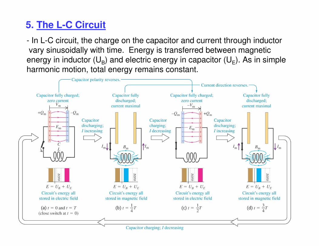
5. The L-C Circuit
- In L-C circuit, the charge on the capacitor and current through inductorvary sinusoidally with time. Energy is transferred between magnetic energy in inductor (UB) and electric energy in capacitor (UE). As in simple harmonic motion, total energy remains constant.
L-C Circuit
� t = 0 � C charged � Q = C Vm
� C discharges through inductor. Because of induced emf in L, the current does not change instantaneously. I starts at 0 until it reaches Im.
� During C discharge, the potential in C = induced emf in L. When potential in C = 0 � induced emf = 0 � maximum Im.
� During the discharge of C, the growing current in L leads to magnetic field �energy stored in C (in its electric field) becomes stored in L (in magnetic field).
� After C fully discharged, some i persists (cannot change instantaneously), C charges with contrary polarity to initial state.
� As current decreases � B decreases � induced emf in same direction as current that slows decrease in current. At some point, B = 0, i =0 and C fully charged with –Vm (-Q on left plate, contrary to initial state).
� If no energy loses, the charges in C oscillate back and forth infinitely �electrical oscillation. Energy is transferred from capacitor E to inductor B.
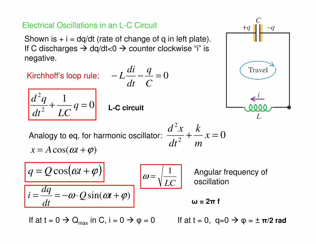
Electrical Oscillations in an L-C Circuit
0=−−C
q
dt
diL
01
2
2
=+ qLCdt
qd
02
2
=+ xm
k
dt
xd
)cos( ϕω += tAx
( )ϕω += tQq cos
LC
1=ω
)sin( ϕωω +⋅−== tQdt
dqi
Shown is + i = dq/dt (rate of change of q in left plate).If C discharges � dq/dt<0 � counter clockwise “i” is negative.
Kirchhoff’s loop rule:
L-C circuit
Analogy to eq. for harmonic oscillator:
Angular frequency of oscillation
ω = 2π f
If at t = 0 � Qmax in C, i = 0 � φ = 0 If at t = 0, q=0 � φ = ± π/2 rad
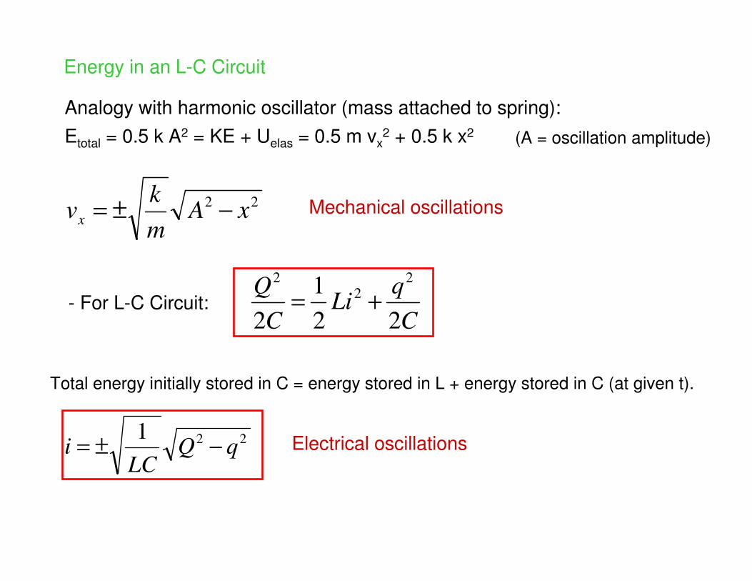
Energy in an L-C Circuit
22xA
m
kvx −±=
C
qLi
C
Q
22
1
2
2
2
2
+=
221qQ
LCi −±=
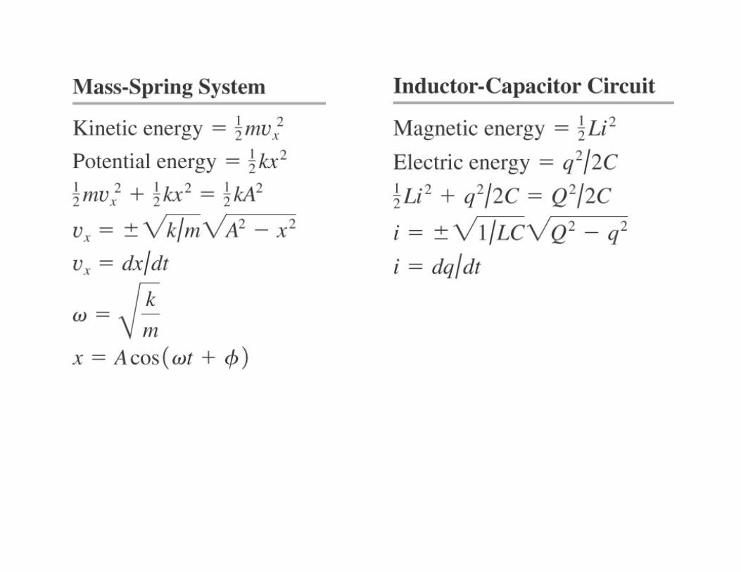
Analogy with harmonic oscillator (mass attached to spring):
Etotal = 0.5 k A2 = KE + Uelas = 0.5 m vx2 + 0.5 k x2 (A = oscillation amplitude)
- For L-C Circuit:
Total energy initially stored in C = energy stored in L + energy stored in C (at given t).
Mechanical oscillations
Electrical oscillations
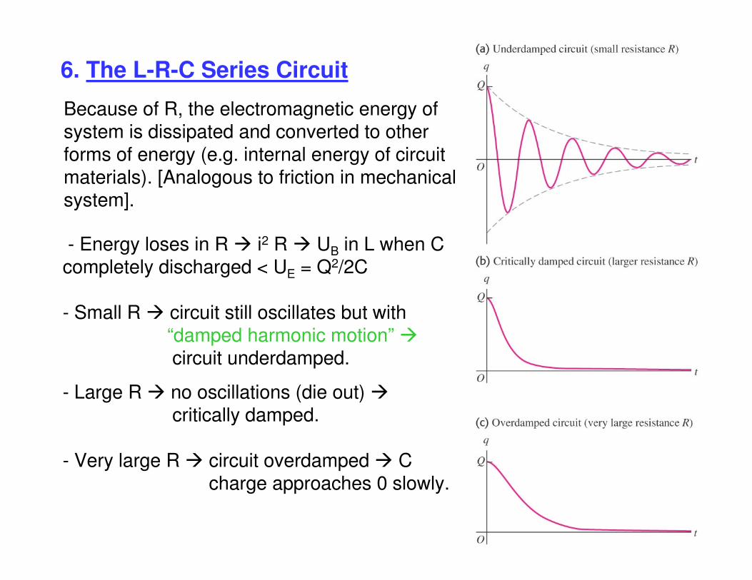
6. The L-R-C Series Circuit
Because of R, the electromagnetic energy of system is dissipated and converted to other forms of energy (e.g. internal energy of circuitmaterials). [Analogous to friction in mechanical system].
- Energy loses in R � i2 R � UB in L when Ccompletely discharged < UE = Q2/2C
- Small R � circuit still oscillates but with “damped harmonic motion” �circuit underdamped.
- Large R � no oscillations (die out) �critically damped.
- Very large R � circuit overdamped � C charge approaches 0 slowly.
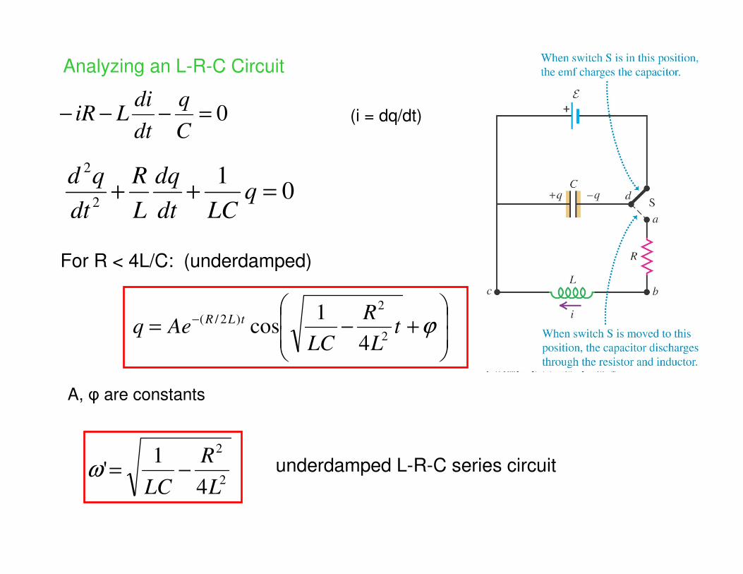
Analyzing an L-R-C Circuit
0=−−−C
q
dt
diLiR
+−= − ϕt
L
R
LCAeq
tLR
2
2
)2/(
4
1cos
01
2
2
=++ qLCdt
dq
L
R
dt
qd
2
2
4
1'
L
R
LC−=ω
For R < 4L/C: (underdamped)
A, φ are constants
underdamped L-R-C series circuit
(i = dq/dt)
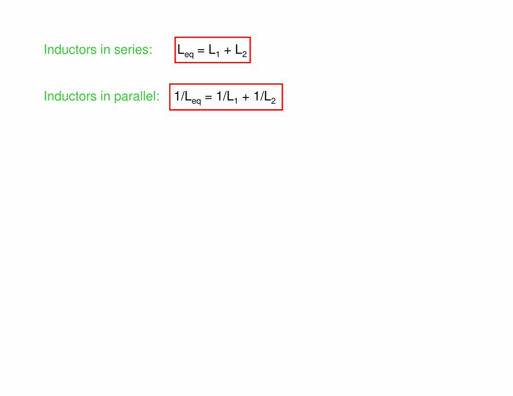
Inductors in series: Leq = L1 + L2
Inductors in parallel: 1/Leq = 1/L1 + 1/L2