Embed Size (px)
Citation preview
10900-01320
CO2 Compression Using SupersonicShock Wave Technology
Project NT42651
March 26, 2009
Shawn LawlorRamgen Power Systems
20900-01320
Forward Looking Statement
Some of the information contained in this document contains “forward-looking statements”. In many cases you can identify forward-looking statements by terminology such as “may,” “will,” “should,” “expects,” “plans,” “anticipates,” “estimates,” “predicts,” “potential,” or “continue,” or the negative of such terms and other comparable terminology. Forward-looking statements are only predictions and as such inherently include risks and uncertainties. Actual events or results may differ materially as a result of risks facing Ramgen Power Systems, LLC (“Ramgen”) or actual results differing from the assumptions underlying such statements. These forward-looking statements are made only as of the date of this presentation, and Ramgen undertakes no obligation to update or revise the forward-looking statements, whether as a result of new information, future events or otherwise. Your decision to remain and receive the information about to be presented to you shall constitute your unconditional acceptance to the foregoing.
30900-01320
The Company – Brief Background
• Privately held since 1993, headquartered in Bellevue, WA• Development and test of supersonic turbo-components for process
gas and power generation applications• 1998-present, $30 M in private funds and $25.0 M in DOE, DOD
and CEC PIER support• 2008-Dresser-Rand investment of up to $49M to commercialize
supersonic compression technology• Novel technology permits high pressure ratios and efficiencies• Recent DOE Funded tests validate capability of compression stage• 26 full-time employees
− Ingersoll-Rand, CAT/Solar, P&W, Boeing, Honeywell, Rocketdyne− 3 PhD & 9 MS Degreed Engineers
40900-01320
Project Overview
• Funding (DOE and Cost Share)– Total Funding – Current Contract $16,109,211 (DE-FC26-06NT42651)– DOE – $9,494,456– Ramgen – $6,614,665
• Overall Project Performance Dates– May 10, 2006 – January 9, 2011
• Project Participants– DOE– Ramgen
▪ Dresser-Rand – Integrated demonstration tests▪ Naval Post Graduate School Turbo Machinery Laboratory – static component testing▪ Consulting engineering organizations
• Overall Project Objectives (SOPO)– Incorporate lessons learned from previous Ramgen shock compression test
programs and recommendations from industry partner Dresser-Rand to define and execute improvements in development plan for large scale demonstration of novel CO2 compression technology
50900-01320
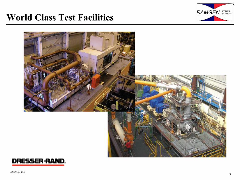
World Class Test Facilities
60900-01320
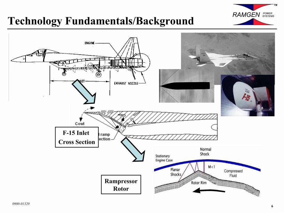
Technology Fundamentals/Background
F-15 Inlet Cross Section
RampressorRotor
70900-01320
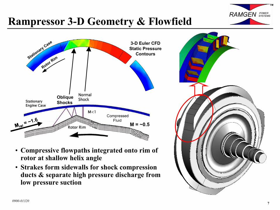
Rampressor 3-D Geometry & Flowfield
• Compressive flowpaths integrated onto rim of rotor at shallow helix angle
• Strakes form sidewalls for shock compression ducts & separate high pressure discharge from low pressure suction
Mrel = ~1.6M = ~0.5Mrel = ~1.6M = ~0.5
3-D Euler CFDStatic Pressure
Contours
ObliqueShocks
Rotor RimStatio
nary Case
80900-01320
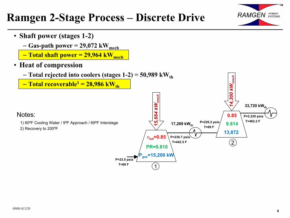
• Shaft power (stages 1-2)– Gas-path power = 29,072 kWmech
– Total shaft power = 29,964 kWmech
• Heat of compression– Total rejected into coolers (stages 1-2) = 50,989 kWth
– Total recoverable1 = 28,986 kWth
Ramgen 2-Stage Process – Discrete Drive
Notes:1) 60ºF Cooling Water / 9ºF Approach / 69ºF Interstage2) Recovery to 200ºF
14,3
00 k
Wm
ech
Pgas=15,200 kW
17,269 kWth
ηad=0.85
P=23.5 psiaT=69 F
P=230.7 psiaT=442.5 F
P=2,220 psiaT=462.2 F
1
2
13,872
0.85
PR=9.810
9.814P=226.2 psiaT=69 F 15
,664
kW
mec
h
33,720 kWth
90900-01320
1
10
100
1,000
10,000
-100 0 100 200 300 400 500
Temperature (F)
Pres
sure
(bar
)
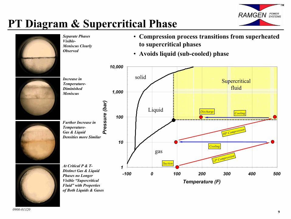
PT Diagram & Supercritical Phase
Suction
Cooling
LP Compression
HP Compression
Discharge
Cooling
Separate Phases Visible-Meniscus Clearly Observed
Increase in Temperature-Diminished Meniscus
Further Increase in Temperature-Gas & Liquid Densities more Similar
At Critical P & T-Distinct Gas & Liquid Phases no Longer Visible “Supercritical Fluid” with Properties of Both Liquids & Gases
• Compression process transitions from superheated to supercritical phases
• Avoids liquid (sub-cooled) phase
solid
Liquid
gas
Supercriticalfluid
100900-01320
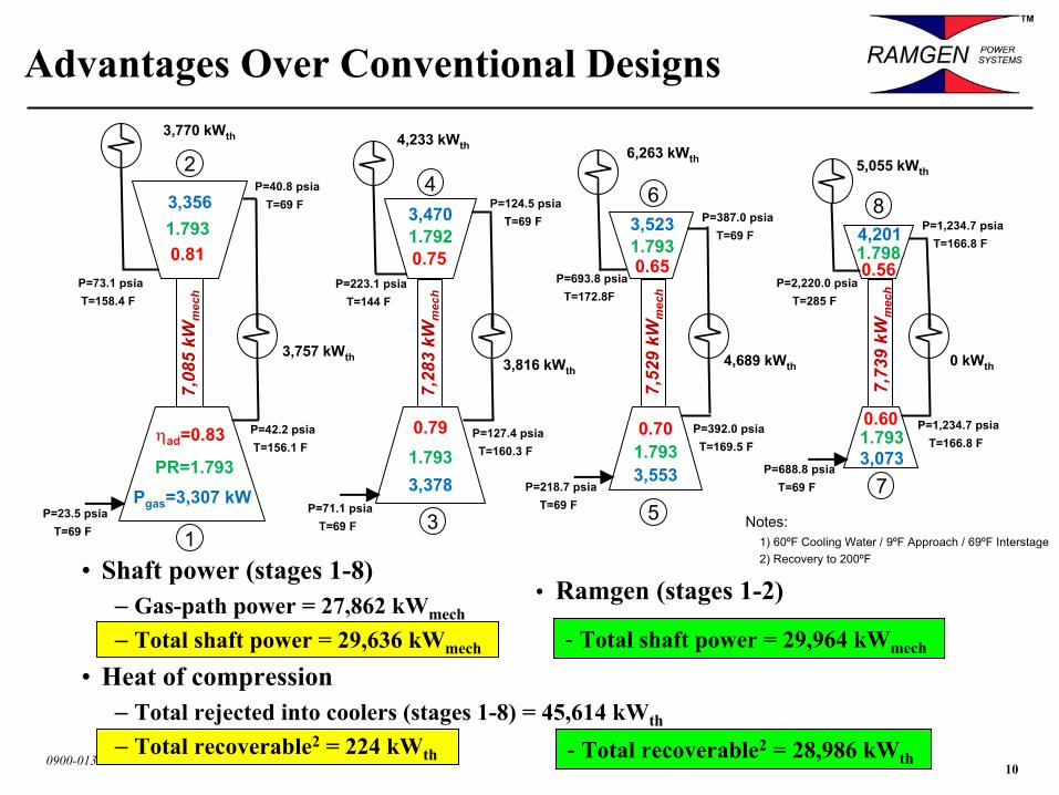
• Shaft power (stages 1-8)– Gas-path power = 27,862 kWmech
– Total shaft power = 29,636 kWmech
• Heat of compression– Total rejected into coolers (stages 1-8) = 45,614 kWth
– Total recoverable2 = 224 kWth
Advantages Over Conventional Designs3,770 kWth
6
7,52
9 kW
mec
h
5
0.70
3,553
3,523
0.65
6,263 kWth
4,689 kWth
P=218.7 psiaT=69 F
P=127.4 psiaT=160.3 F
7,28
3 kW
mec
h
4
3
0.79
3,378
3,470
0.75
4,233 kWth
3,816 kWth
P=71.1 psiaT=69 F
P=124.5 psiaT=69 F
P=223.1 psiaT=144 F
P=392.0 psiaT=169.5 F
P=387.0 psiaT=69 F
P=693.8 psiaT=172.8F
P=40.8 psiaT=69 F
Pgas=3,307 kW
3,757 kWth
ηad=0.83
P=23.5 psiaT=69 F
P=42.2 psiaT=156.1 F
7,08
5 kW
mec
h
P=73.1 psiaT=158.4 F
1
2
3,356
0.81
PR=1.793
1.793
1.793
1.792
1.793
1.793
7,73
9 kW
mec
h
8
7
4,201
0.56
0.60
3,073
5,055 kWth
0 kWth
P=688.8 psiaT=69 F
P=1,234.7 psiaT=166.8 F
P=1,234.7 psiaT=166.8 F
P=2,220.0 psiaT=285 F
1.798
1.793
Notes:1) 60ºF Cooling Water / 9ºF Approach / 69ºF Interstage2) Recovery to 200ºF
- Total shaft power = 29,964 kWmech
• Ramgen (stages 1-2)
- Total recoverable2 = 28,986 kWth
110900-01320
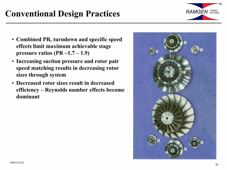
• Combined PR, turndown and specific speed effects limit maximum achievable stage pressure ratios (PR ~1.7 – 1.9)
• Increasing suction pressure and rotor pair speed matching results in decreasing rotor sizes through system
• Decreased rotor sizes result in decreased efficiency – Reynolds number effects become dominant
Conventional Design Practices
120900-01320
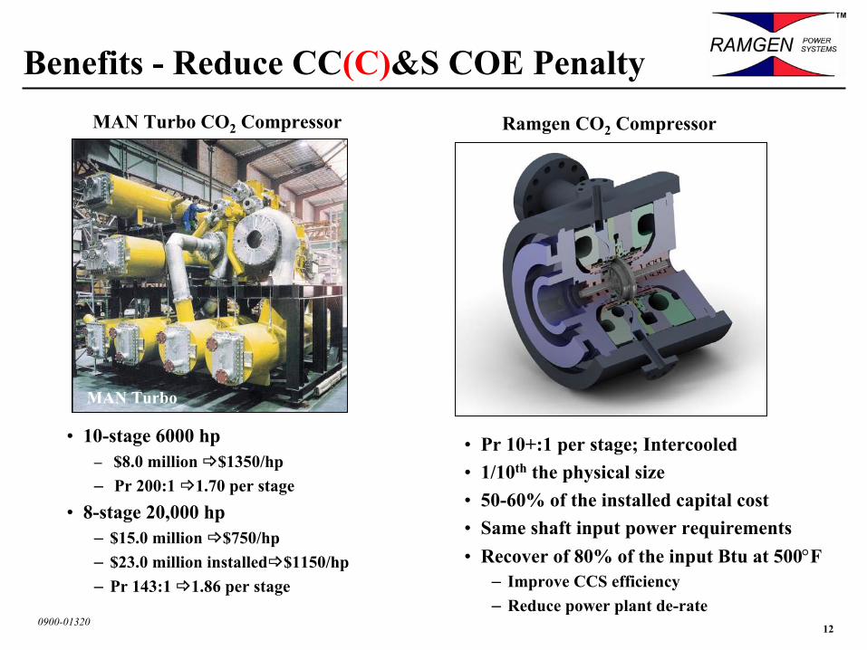
Ramgen CO2 Compressor
Benefits - Reduce CC(C)&S COE Penalty
• 10-stage 6000 hp– $8.0 million $1350/hp– Pr 200:1 1.70 per stage
• 8-stage 20,000 hp– $15.0 million $750/hp– $23.0 million installed $1150/hp– Pr 143:1 1.86 per stage
MAN Turbo
• Pr 10+:1 per stage; Intercooled• 1/10th the physical size• 50-60% of the installed capital cost• Same shaft input power requirements• Recover of 80% of the input Btu at 500°F
– Improve CCS efficiency– Reduce power plant de-rate
MAN Turbo CO2 Compressor
130900-01320
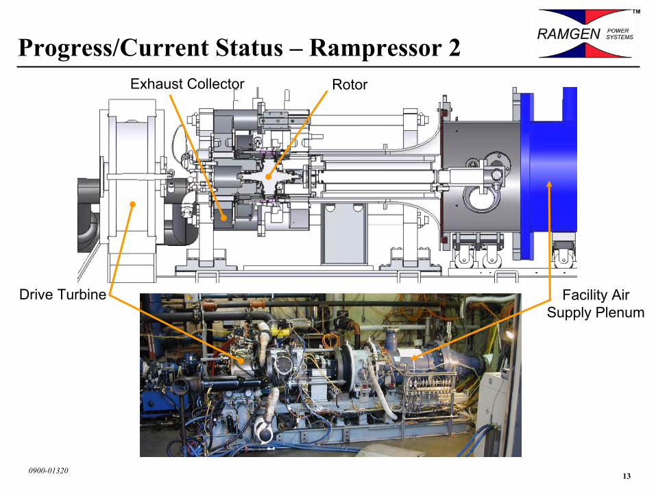
Progress/Current Status – Rampressor 2
Drive Turbine
RotorExhaust Collector
Facility Air Supply Plenum
140900-01320
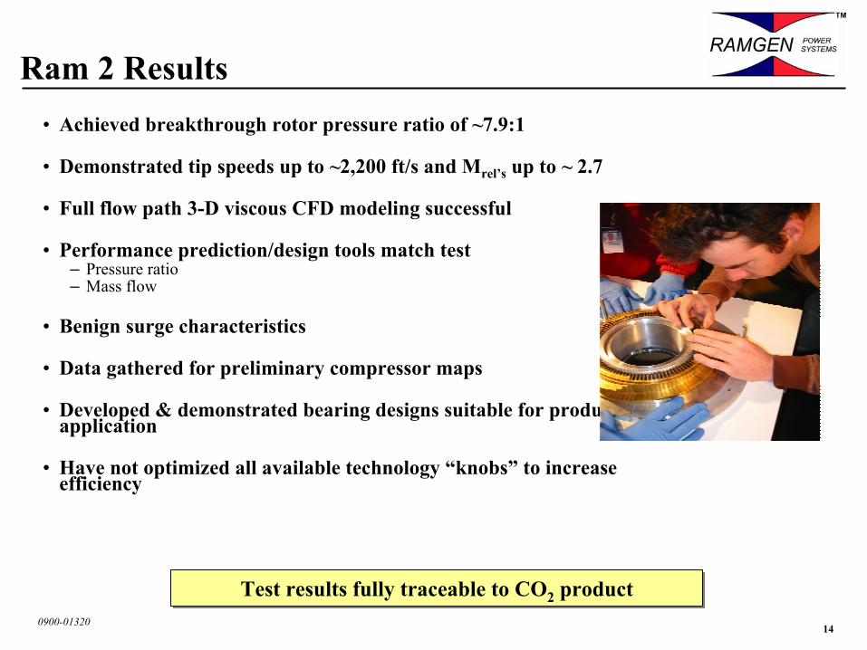
Ram 2 Results• Achieved breakthrough rotor pressure ratio of ~7.9:1
• Demonstrated tip speeds up to ~2,200 ft/s and Mrel’s up to ~ 2.7
• Full flow path 3-D viscous CFD modeling successful
• Performance prediction/design tools match test– Pressure ratio– Mass flow
• Benign surge characteristics
• Data gathered for preliminary compressor maps
• Developed & demonstrated bearing designs suitable for product application
• Have not optimized all available technology “knobs” to increase efficiency
Test results fully traceable to CO2 productTest results fully traceable to CO2 product
150900-01320
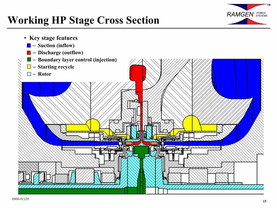
Working HP Stage Cross Section• Key stage features
– Suction (inflow)– Discharge (outflow)– Boundary layer control (injection)– Starting recycle– Rotor
160900-01320
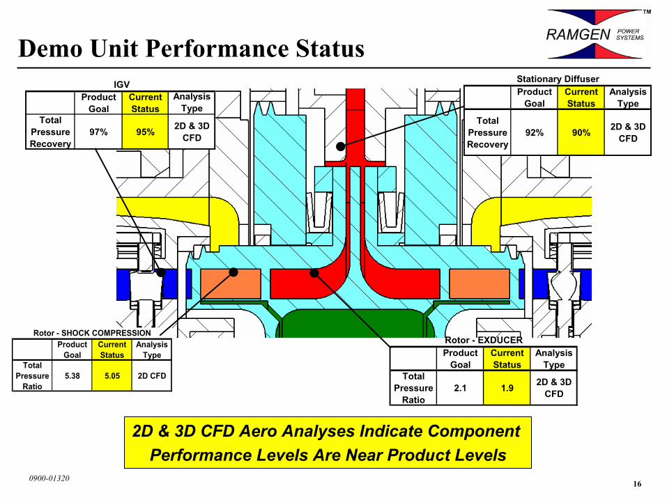
Demo Unit Performance StatusIGV
Product Goal
Current Status
Analysis Type
Total Pressure Recovery
97% 95% 2D & 3D CFD
2D & 3D CFD Aero Analyses Indicate Component Performance Levels Are Near Product Levels
Product Goal
Current Status
Analysis Type
Total Pressure
Ratio5.38 5.05 2D CFD
Rotor - SHOCK COMPRESSION
Product Goal
Current Status
Analysis Type
Total Pressure Recovery
92% 90% 2D & 3D CFD
Stationary Diffuser
Product Goal
Current Status
Analysis Type
Total Pressure
Ratio2.1 1.9 2D & 3D
CFD
Rotor - EXDUCER
170900-01320
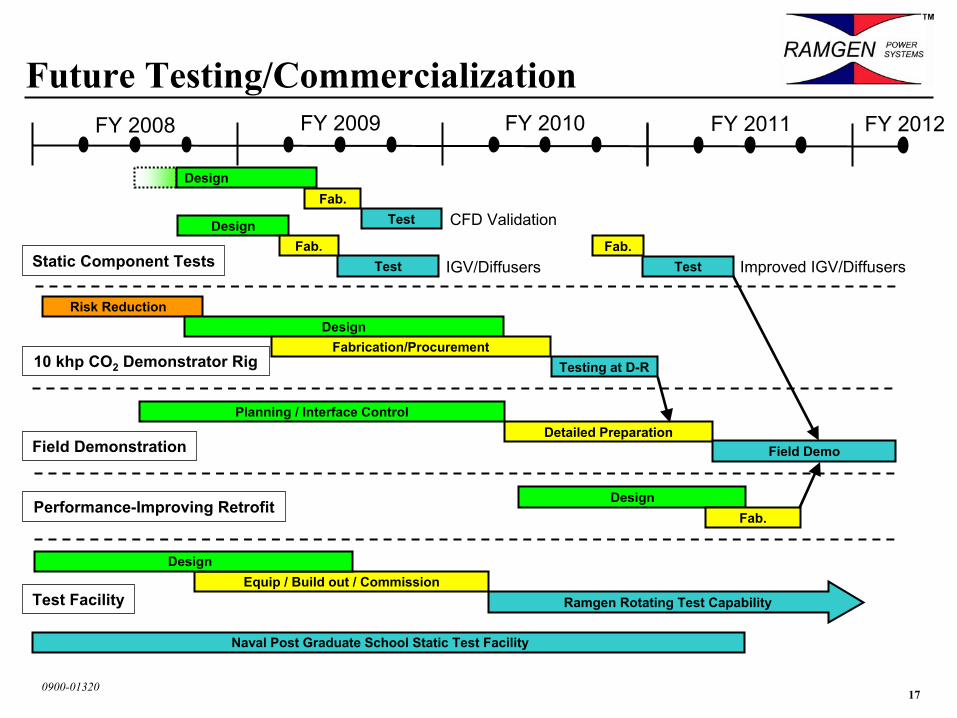
Future Testing/Commercialization
Static Component Tests
10 khp CO2 Demonstrator Rig
CFD Validation
IGV/Diffusers
FY 2008 FY 2009 FY 2010 FY 2011
Performance-Improving Retrofit
Improved IGV/Diffusers
Field Demonstration
DesignRisk Reduction
Test
DesignFab.
Testing at D-RFabrication/Procurement
Fab.Test
Design
Design
TestFab.
Fab.
Planning / Interface ControlDetailed Preparation
Field Demo
FY 2012
Equip / Build out / CommissionTest Facility Ramgen Rotating Test Capability
Design
Naval Post Graduate School Static Test Facility
180900-01320
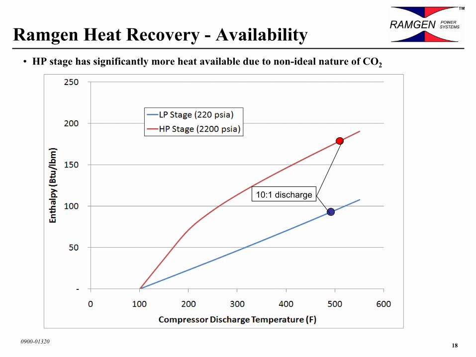
Ramgen Heat Recovery - Availability• HP stage has significantly more heat available due to non-ideal nature of CO2
10:1 discharge
190900-01320
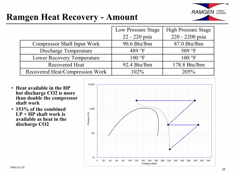
Ramgen Heat Recovery - AmountLow Pressure Stage High Pressure Stage
22 - 220 psia 220 - 2200 psiaCompressor Shaft Input Work 90.6 Btu/lbm 87.0 Btu/lbm
Discharge Temperature 489 °F 509 °FLower Recovery Temperature 100 °F 100 °F
Recovered Heat 92.4 Btu/lbm 178.8 Btu/lbmRecovered Heat/Compression Work 102% 205%
• Heat available in the HP hot discharge CO2 is more than double the compressor shaft work
• 153% of the combined LP + HP shaft work is available as heat in the discharge CO2
10
100
1,000
10,000
0 20 40 60 80 100 120 140 160 180 200 220 240 260 280 300 320 340Enthalpy, Btu/lb
Pre
ssur
e, P
si
200900-01320
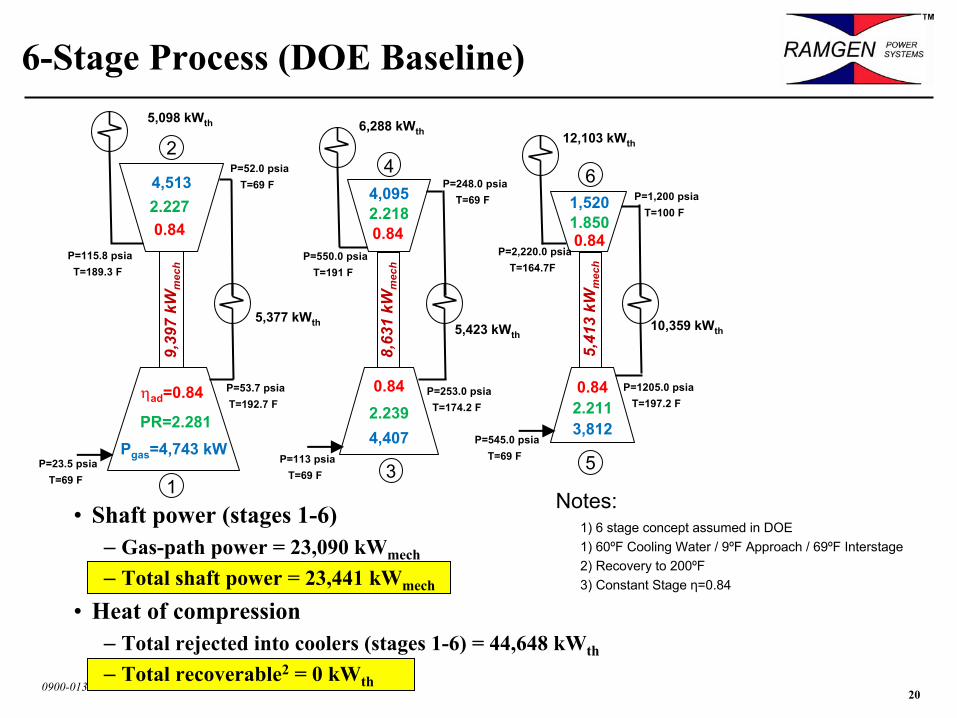
• Shaft power (stages 1-6)– Gas-path power = 23,090 kWmech
– Total shaft power = 23,441 kWmech
• Heat of compression– Total rejected into coolers (stages 1-6) = 44,648 kWth
– Total recoverable2 = 0 kWth
6-Stage Process (DOE Baseline)5,098 kWth
6
5,41
3 kW
mec
h
5
0.84
3,812
1,520
0.84
12,103 kWth
10,359 kWth
P=545.0 psiaT=69 F
P=253.0 psiaT=174.2 F
8,63
1 kW
mec
h
4
3
0.84
4,407
4,095
0.84
6,288 kWth
5,423 kWth
P=113 psiaT=69 F
P=248.0 psiaT=69 F
P=550.0 psiaT=191 F
P=1205.0 psiaT=197.2 F
P=1,200 psiaT=100 F
P=2,220.0 psiaT=164.7F
P=52.0 psiaT=69 F
Pgas=4,743 kW
5,377 kWth
ηad=0.84
P=23.5 psiaT=69 F
P=53.7 psiaT=192.7 F
9,39
7 kW
mec
h
P=115.8 psiaT=189.3 F
1
2
4,513
0.84
PR=2.281
2.227
2.239
2.218
2.211
1.850
Notes:1) 6 stage concept assumed in DOE1) 60ºF Cooling Water / 9ºF Approach / 69ºF Interstage2) Recovery to 200ºF3) Constant Stage η=0.84


![30 Supersonic Aerodynamics[1]](https://img.pdfslide.tips/doc/110x75/55cf9b06550346d033a46d23/30-supersonic-aerodynamics1.jpg)