Embed Size (px)
Citation preview

PROJECT 39 - DEVELOPMENT OF GAS SUPERSONIC SEPARATORS - OPTIMISATION, NUMERICAL SIMULATION AND EXPERIMENTS
Paulo V. M. Yamabe¹, Breno A. Avancini² , Douglas Serson², Jairo P. C. Filho², Ulisses A. S. Costa²,
Julián Restrepo², Reinaldo M. Orselli³, Marcelo T. Hayashi³, José R. S. Moreira² , Julio R.
Meneghini¹, Bruno S. Carmo², Ernani V. Volpe ², Emilio C. N. Silva¹
¹ Department of Mechatronics Engineering and Mechanical Systems, University of São Paulo
² Department of Mechanical Engineering, University of São Paulo
³ Department of Aerospace Engineering, Federal University of ABC
V WORKSHOP INTERNO RCGI
21 e 22 de agosto de 2018

RESEARCH CENTRE FOR GAS INNOVATION
Outline
• Introduction
• WCCM Presentation: Comparison between numerical approaches to simulate a supersonic nozzle
• Parametric Optimization (second throat)
• Shape Optimization
2

RESEARCH CENTRE FOR GAS INNOVATION
Outline
• Introduction
• WCCM Presentation: Comparison between numerical approaches to simulate a supersonic nozzle
• Parametric Optimization
• Shape Optimization
3
RESEARCH CENTRE FOR GAS INNOVATION
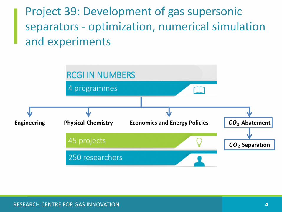
Project 39: Development of gas supersonic separators - optimization, numerical simulation and experiments
4
Engineering Physical-Chemistry Economics and Energy Policies 𝑪𝑶𝟐 Abatement
𝑪𝑶𝟐 Separation

RESEARCH CENTRE FOR GAS INNOVATION
Supersonic Separator
5
𝐶𝐻4 + 𝐶𝑂2
𝐶𝐻4
𝐶𝑂2
𝐶𝑂2
Fixedblades
Uses the cooling properties of a converging-diverging nozzle with the principles of centrifugal separation
Advantages: Compact, no moving parts, no extra chemical products

RESEARCH CENTRE FOR GAS INNOVATION
Outline
• Introduction
• WCCM Presentation: Comparison between numerical approaches to simulate a supersonic nozzle
• Parametric Optimization
• Shape Optimization
7

RESEARCH CENTRE FOR GAS INNOVATION
Comparison between numerical approaches to simulate a supersonic nozzle
• 13th World Congress on Computational Mechanics, July 22-27, New York-USA
• Objective: Use different numerical approaches for the same test case and compare the results (i.e. shock position, Stagnation Temperature conservation)
8
RESEARCH CENTRE FOR GAS INNOVATION
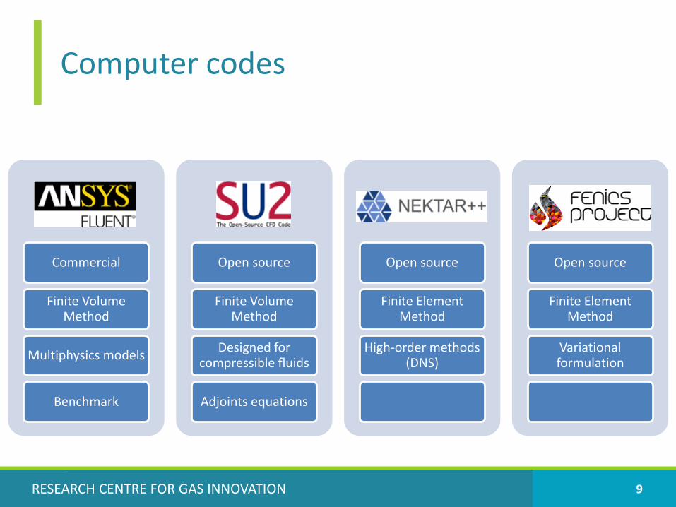
Computer codes
9
Fluent
Commercial
Finite Volume Method
Multiphysics models
Benchmark
SU2
Open source
Finite Volume Method
Designed for compressible fluids
Adjoints equations
Nektar
Open source
Finite Element Method
High-order methods (DNS)
FEniCS
Open source
Finite Element Method
Variational formulation

RESEARCH CENTRE FOR GAS INNOVATION
Main Hypothesis
11
• Inviscid (2D Compressible Euler equations)
• Perfect Gas
• No phase change
• Single component

RESEARCH CENTRE FOR GAS INNOVATION
Geometry and boundary conditions
12
𝑇0291.30𝐾
𝑃0104071.61 𝑃𝑎
𝑃83049𝑃𝑎Slip
𝐴𝑟𝑒𝑎 𝑥 = 2.5 + 3𝑥
5− 1.5
𝑥
5
2
𝑓𝑜𝑟 𝑥 ≤ 5
𝐴𝑟𝑒𝑎 𝑥 = 3.5 −𝑥
56 − 4.5
𝑥
5+
𝑥
5
2
𝑓𝑜𝑟 𝑥 > 5
Arina R., Numerical simulation of near-critical fluids, Applied Numerical Mathematics, Volume 51, Issue 4, 2004, Pages 409-426, ISSN 0168-9274,https://doi.org/10.1016/j.apnum.2004.06.002.

RESEARCH CENTRE FOR GAS INNOVATION
Mesh
13
12600 elements
Results compared at the center line of the geometry (y=0)

RESEARCH CENTRE FOR GAS INNOVATION
Comparison - Density [𝑘𝑔/𝑚3]
14
0,45
0,55
0,65
0,75
0,85
0,95
1,05
1,15
1,25
0,0 1,0 2,0 3,0 4,0 5,0 6,0 7,0 8,0 9,0 10,0
Fluent Nektar FEniCS SU2

RESEARCH CENTRE FOR GAS INNOVATION
Comparison - Density [𝑘𝑔/𝑚3]- (zoom)
15
0,45
0,55
0,65
0,75
0,85
0,95
1,05
6,85 6,90 6,95 7,00 7,05 7,10 7,15
Fluent Nektar FEniCS SU2

RESEARCH CENTRE FOR GAS INNOVATION
Comparison –Stagnation Temperature [𝑲]
16
286
287
288
289
290
291
292
293
294
295
296
297
0,0 1,0 2,0 3,0 4,0 5,0 6,0 7,0 8,0 9,0 10,0
Fluent Nektar FEniCS SU2

RESEARCH CENTRE FOR GAS INNOVATION
Comparison –Stagnation Temperature [𝑲]
17
0.96%
1.59%
1.83%
286
287
288
289
290
291
292
293
294
295
296
297
6,60 6,70 6,80 6,90 7,00 7,10 7,20 7,30 7,40
Fluent Nektar FEniCS SU2

RESEARCH CENTRE FOR GAS INNOVATION
Conclusion of comparison
18
• Shock position: – All numerical approaches predicted the shock near 7.0– Nektar predicted the shock upstream
• Total Temperature conservation:– FVM (Fluent and SU2) - no oscillations– FEM (Nektar and FEniCS) - oscillations near shock
• Cannot discard any of the computer programs (yet)– Can improve the results with some tuning (using different methods and
schemes)
• Still needs experimental tests to validate the solvers (for this particular case)

RESEARCH CENTRE FOR GAS INNOVATION
Outline
• Introduction
• WCCM Presentation: Comparison between numerical approaches to simulate a supersonic nozzle
• Parametric Optimization (second throat)
• Shape Optimization
19

RESEARCH CENTRE FOR GAS INNOVATION
CFD flow modeling
• Fluent
• Turbulence model: 𝑘𝜖 − 𝑅𝑁𝐺;
• Equation of state: Ideal gas;
• Main assumptions of the flow:
– Adiabatic flow;
– No chemical reactions;
– Gases flowing in equilibrium;
21

RESEARCH CENTRE FOR GAS INNOVATION
Second throat – Geometry definition
23
𝑦4 = 𝑦3 − 𝑦3 − 𝑦2 ∗ 𝑓𝑎𝑐𝑡𝑜𝑟ሻ𝑦3 = 𝑦𝐴𝑟𝑖𝑛𝑎(𝑥
Mach number field in 6.4-0.4 geometry
Geometry code: 𝑥 - 𝑓𝑎𝑐𝑡𝑜𝑟
RESEARCH CENTRE FOR GAS INNOVATION
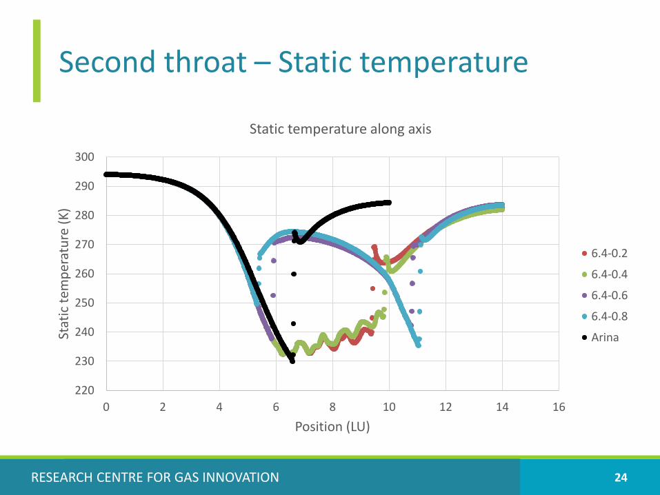
Second throat – Static temperature
24
220
230
240
250
260
270
280
290
300
0 2 4 6 8 10 12 14 16
Stat
icte
mp
erat
ure
(K)
Position (LU)
Static temperature along axis
6.4-0.2
6.4-0.4
6.4-0.6
6.4-0.8
Arina

RESEARCH CENTRE FOR GAS INNOVATION
Second throat – Total pressure
25
97000
98000
99000
100000
101000
102000
103000
104000
105000
0 2 4 6 8 10 12 14 16
Tota
l Pre
ssu
re(P
a)
Position (LU)
Total pressure along axis
6.4-0.2
6.4-0.4
6.4-0.6
6.4-0.8
Arina

RESEARCH CENTRE FOR GAS INNOVATION
Outline
• Introduction
• WCCM Presentation: Comparison between numerical approaches to simulate a supersonic nozzle
• Parametric Optimization
• Shape Optimization
26

RESEARCH CENTRE FOR GAS INNOVATION
CH4 as an Ideal Gas: Stagnation properties
27
Stagnation pressure [Pa]
Stagnation temperature [K]

RESEARCH CENTRE FOR GAS INNOVATION 28
CH4 as an ideal gas: Temperaturedistribution [Celsius]

RESEARCH CENTRE FOR GAS INNOVATION 29
CH4 as an ideal gas: Pressure distributionat several Optimization Cycles
Method: Hicks-Henne bump functions

RESEARCH CENTRE FOR GAS INNOVATION
Next Steps
• Use different computer codes: OpenFOAM, Comsol, CFD++
• Study the influence of the collector
• Study Turbulence models
• Study shape optimization
• Study real gas effects
• Implement topology optimization

RESEARCH CENTRE FOR GAS INNOVATION

RESEARCH CENTRE FOR GAS INNOVATION
Next Steps
• Use different computer codes: OpenFOAM, Comsol, CFD++
• Study the influence of the collector
• Study Turbulence models
• Improve shape optimization
• Study real gas effects
• Implement topology optimization

THANK YOU