Embed Size (px)
Citation preview
International Journal of Electronics and Communication Engineering & Technology (IJECET), ISSN 0976
– 6464(Print), ISSN 0976 – 6472(Online) Volume 3, Issue 1, January- June (2012), © IAEME
1
CORNER TRUNCATED INVERTED U - SLOT TRIPLE BAND
TUNABLE RECTANGULAR MICROSTRIP ANTENNA FOR WLAN
APPLICATIONS
Nagraj Kulkarni1
and S. N. Mulgi2
Department of PG Studies and Research in Applied Electronics,
Gulbarga University, Gulbarga-585106, Karnataka, India
Email: [email protected]
ABSTRACT
This paper presents the design and development of simple corner truncated rectangular
microstrip antenna comprising inverted U-slot on the radiating patch for triple band and
tunable operation. The proposed antenna is excited through microstripline. The low cost
glass epoxy substrate material is used to fabricate the antenna. The antenna operates
between 4.74 to 9.59 GHz for three frequency bands and gives broadside radiation
characteristics. The tuning of secondary bands can be achieved by varying the width of
inverted U-slot. The experimental and simulated results are in good agreement with each
other. The proposed antenna may find applications in WLAN.
Key words: Corner truncated, microstrip antenna, triple band, tuning.
1. INTRODUCTION
Microstrip antennas are becoming increasingly popular because of their small size,
lightweight, low cost, easy to fabricate and compatible to microwave integrated circuits
[1-2]. However, the modern communication systems such as wireless local area networks
(WLAN) often require antennas possessing two or more discrete frequency bands, which
can avoid the use of multiple antennas. The multiband microstrip antennas are designed
by cutting slots of different geometries like bow-tie, rectangular, square ring, annular ring
etc. on the radiating patch [3-6]. The tuning of the bands is achieved by incorporating
shorting pins, open and closed stubs, shorting posts and use of active devices with
variable biasing voltages [7-12] etc. But the multiband operation and tuning of the
INTERNATIONAL JOURNAL OF ELECTRONICS AND
COMMUNICATION ENGINEERING & TECHNOLOGY (IJECET)
ISSN 0976 – 6464(Print) ISSN 0976 – 6472(Online)
Volume 3, Issue 1, January- June (2012), pp. 01-09
© IAEME: www.iaeme.com/ijecet.html
Journal Impact Factor (2011)- 0.8500 (Calculated by GISI)
www.jifactor.com
IJECET
© I A E M E
International Journal of Electronics and Communication Engineering & Technology (IJECET), ISSN 0976
– 6464(Print), ISSN 0976 – 6472(Online) Volume 3, Issue 1, January- June (2012), © IAEME
2
operating bands using planar corner truncated inverted U-slot rectangular microstrip
antenna is found to be rare in the literature.
2. DESIGNING OF ANTENNA
The conventional rectangular microstrip antenna (CRMSA) and corner truncated inverted
U-slot rectangular microstrip antenna (CTIUSRMSA) are fabricated on low cost glass
epoxy substrate material of thickness h = 1.6 mm and dielectric constant εr = 4.2. The
artwork of CRMSA and CTIUSRMSA is developed using computer software AUTO
CAD to achieve better accuracy. The antennas are etched by photolithography process.
The bottom surface of the substrate consists of a tight ground plane copper shielding.
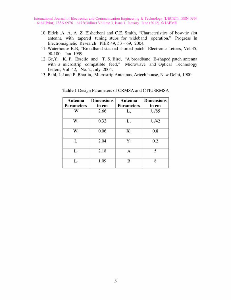
Figure 1 shows the top view geometry of CRMSA. This antenna is designed for the
resonant frequency of 3.5 GHz using the equations available in the literature for the
design of rectangular microstrip antenna on the substrate area A x B [13]. This antenna
consists of a radiating patch of length L and width W. A quarter wave transformer of
length Lt and width Wt is incorporated to match the impedances between CP and
microstripline feed of length Lf and width Wf. A 50 Ω semi miniature-A (SMA)
connector is used at the tip of the microstripline to feed the microwave power.
Figure 2 shows the top view geometry CTIUSRMSA which is constructed from CRMSA.
Two diagonally opposite corners of CRMSA are truncated as Xd and Yd. The novel
inverted U slot is placed at the center of the rectangular radiating patch. Lh and Lv are
the lengths of horizontal and vertical arms of inverted U slot respectively. The
dimensions Lh and Lv are taken in terms of λ0, where λ0 is a free space wave length in cm
corresponding to the designed frequency of 3.5 GHz. Uw is the width of the horizontal
and vertical arms of inverted U slot. The inverted U-slot is placed at a distance of 0.305
cm from radiating (W) and 0.415 cm from non-radiating (L) edges of the rectangular
patch respectively. The various parameters of the proposed antennas are listed as in Table
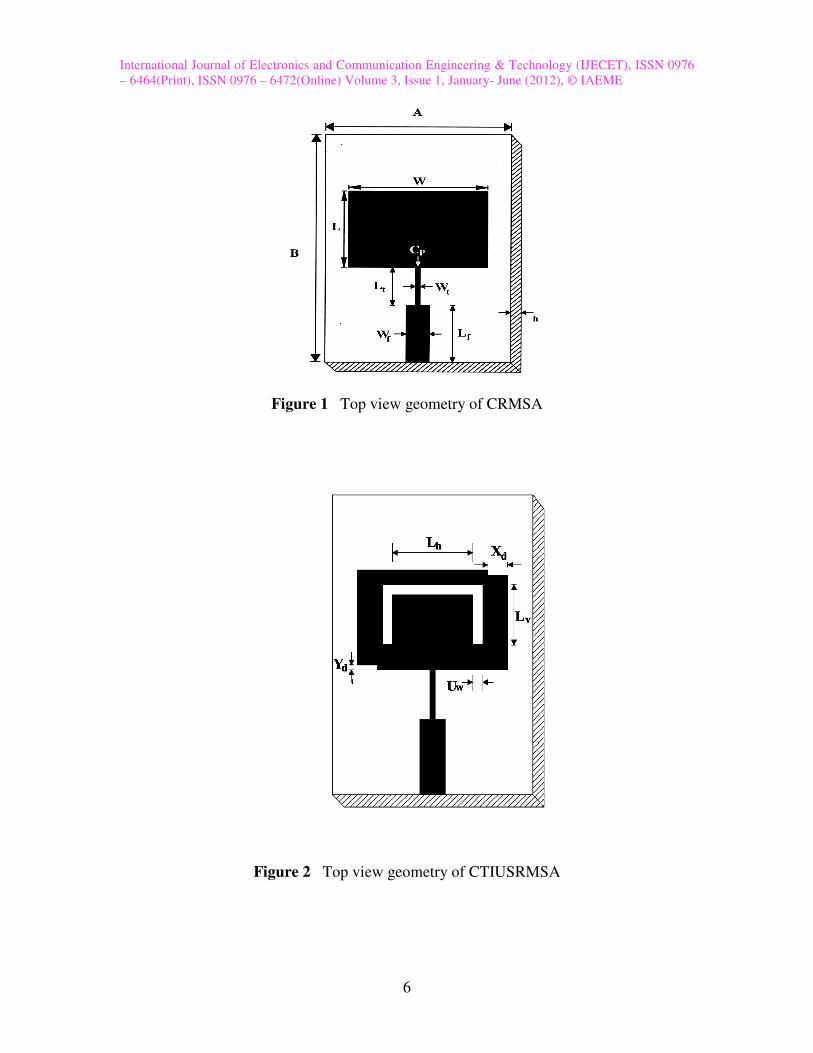
1. Figure 3 (a) and (b) show the 3D view of CRMSA and CTIUSRMSA respectively.
3. EXPERIMENTAL RESULTS
The German make (Rohde and Schwarz, ZVK model 1127.8651) Vector Network
Analyzer is used to measure the experimental return loss of CRMSA and CTIUSRMSA.
The simulation of the CRMSA and CTIUSRMSA is carried out using High Frequency
Structure Simulator (HFSS) software.
Figure 4 shows the variation of return loss versus frequency of CRMSA. From this figure
it is clear that, the CRMSA resonates at 3.39 GHz of frequency which is close to the
designed frequency of 3.5 GHz. The experimental impedance bandwidth over return loss
less than -10dB is calculated using the formula,
2 1
c
( ) = ×100 %Impedance Bandwidth (%)
−
f f
f
International Journal of Electronics and Communication Engineering & Technology (IJECET), ISSN 0976
– 6464(Print), ISSN 0976 – 6472(Online) Volume 3, Issue 1, January- June (2012), © IAEME
3
where, f2 and f1 are the upper and lower cut off frequencies of the resonating band when
its return loss reaches -10 dB and fc is a centre frequency between f1 and f2. The
impedance bandwidth of CRMSA is found to be 3.27 %. The simulated result of CRMSA
is also shown in Fig. 4.
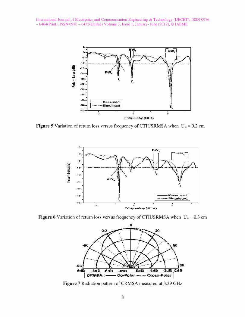
Figure 5 shows the variation of return loss versus frequency of CTIUSRMSA. It is clear
from this figure that, the antenna operates for three bands BW1 (4.67-4.82 GHz), BW2
(5.74-6.01 GHz) and BW3 (8.79-9.74 GHz) for the resonating modes of f1, f2 and f3
respectively, when Uw = 0.2 cm. The three bands BW1, BW2 and BW3 are due to the
independent resonance of patch, corner truncated slots and inverted U-slot of
CTIUSRMSA. The BW1 is considered as primary band because its resonating mode f1
remains close to fr of CRMSA. The BW2 and BW3 are considered as secondary bands. It
is observed from Fig. 5 that, the construction of CTIUSRMSA does not affect much the
resonant mode of primary band i.e. f1, but two additional resonating modes appear at f2
and f3. The simulated result of CTIUSRMSA is also shown in Fig. 5 which is in good
agreement with the experimental results. The magnitude of impedance bandwidth of
BW1, BW2 and BW3 are found to be 3.16%, 4.5% and 10.2% respectively. The
frequency ratio f2/f1 of CTIUSRMSA is found to be 1.242.
Figure 6 shows the variation of return loss versus frequency of CTIUSRMSA. It is seen
from this figure that, the antenna operates for three bands BW4 (4.73-4.91 GHz), BW5
(7.48-7.92 GHz) and BW6 (8.93-10.24 GHz) for the resonating modes of f4, f5 and f6
respectively, when Uw is increased from 0.2 to 0.3 cm. It is clear from this figure that,
the resonating modes f5 and f6 are shifted towards higher frequency side when compared
to f2 and f3 respectively, without much shift in the primary resonant mode i.e. f1. This
change in the resonating modes of antenna is due to the increase of Uw from 0.2 to 0.3
cm. The simulated result of CTIUSRMSA is also shown in Fig. 6 which is in good
agreement with the experimental results. The magnitude of impedance bandwidth of
BW4, BW5 and BW6 are found to be 3.73%, 5.71% and 13.55% respectively. The
frequency ratio f5/f4 of CTIUSRMSA is found to be 1.59 indicates shifting of secondary
resonant mode f5 with respect to primary resonant mode f4 .
The gain of the proposed antennas is measured by absolute gain method. The
power transmitted ‘Pt’ by pyramidal horn antenna and power received ‘Pr’ by antenna
under test (AUT) are measured independently. With the help of these experimental data,
the gain (G) dB of AUT is calculated by using the equation,
λP 0r(G) dB=10 log - (G ) dB - 20log dBt
P 4πRt
where, Gt is the gain of the pyramidal horn antenna and R is the distance between the
transmitting antenna and the AUT. The maximum gain CTIUSRMSA measured in BW1
and BW4 are found to be 1.21dB, 1.64 dB respectively.
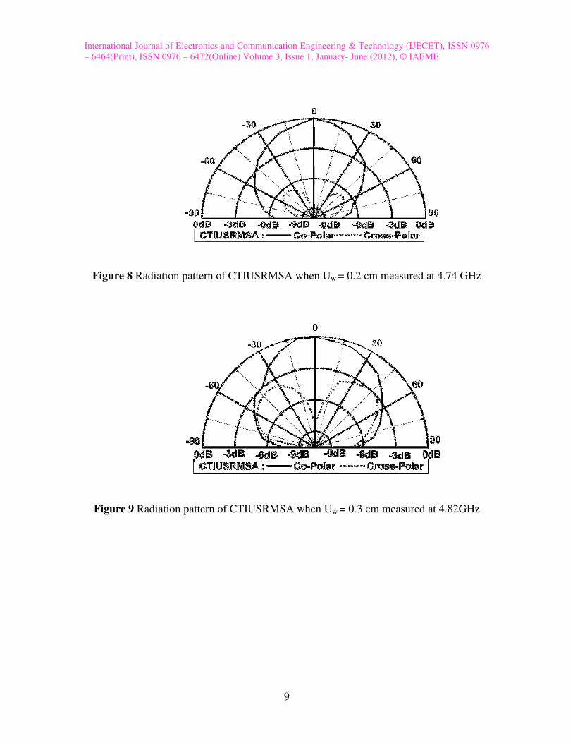
Figure 7-9 show the co-polar and cross-polar radiation pattern of CRMSA and
CTIUSRMSA measured in their operating bands. From these figures it is clear that, the
patterns are broadsided and linearly polarized.
International Journal of Electronics and Communication Engineering & Technology (IJECET), ISSN 0976
– 6464(Print), ISSN 0976 – 6472(Online) Volume 3, Issue 1, January- June (2012), © IAEME
4
4. CONCLUSION
From the detailed experimental study, it is concluded that, the CRMSA can be
made to operate at three frequency bands between 4.74 to 9.59 GHz by loading inverted
U-slot on the radiating patch. The secondary bands of CTIUSRMSA can be tuned to
higher side of the frequency spectrum by increasing the width of horizontal and vertical
arms of inverted U-slot without affecting much the primary band. Tuning of triple bands
does not affect the nature of broadside radiation characteristics. The proposed antennas
are simple in their geometry and are fabricated using low cost glass epoxy substrate
material. The CTIUSRMSA may find applications in wireless local area
network(WLAN).
ACKNOWLEDGMENTS
The authors would like to thank the authorities of Dept. of Science. &
Technology. (DST), Govt. of India, New Delhi, for sanctioning the Vector Network
Analyzer under the FIST project to the Department of Applied Electronics, Gulbarga
University, Gulbarga.
REFRENCES
1. Kin-Lu Wong, Compact and Broad band microstrip Antennas, A Wiley-Inter
Science Publication, John Wiley & Sons. Inc.
2. Garg Ramesh , Bhatia Prakesh, Bahl Inder and Boon Apisakittir (2001),
Microstrip Antennas Design Hand Book, Artech House Inc.
3. Behera. S and Vinoy. K. J, “Microstrip square ring antenna for dual band
operation,” Progress In Electromagnetics Research, PIER 93, 41–56, 2009.
4. Roy . J. S, Chattoraj, and N. Swain, “ short circuited microstrip antenna for
multi-band wireless communications,” Microwave and Optical Technology
Letters, Vol .48, 2372-2375, 2006.
5. Sadat, S , M. Fardis F. Geran, and G. Dadashzadeh,” A compact microstrip
square-ring slot antenna for UWB applications,” Progress In Electromagnetic
Research PIER 67, 173-179, 2007.
6. Shams. K. M Z , M. Ali, and H. S. Hwang, “A planar inductively coupled
bow-tie slot antenna for WLAN application,” Journal of Electromagnetic
Waves and Applications, Vol.20, 86-871, 2006.
7. Kuo, J. S and K. L. Wong, “A compact microstrip antenna with
meandered slots in the ground plane,” Microwave and Optical Technology
Letters, Vol. 29, 95-97, April 2001.
8. Sharma A. and G. Singh, “Design of single pin shorted Three – dielectric
layered substrates rectangular patch microstrip antenna for communication
system,” Progress In Electromagnetic Research PIER 2. 157 – 165, 2008.
9. Ang. B. K and B.K Chung,“A wideband microstrip patch antenna for 5-6 GHz
Wireless communication,” Progress In Electromagnetic Research PIER 75,
397-407, 2007.
International Journal of Electronics and Communication Engineering & Technology (IJECET), ISSN 0976
– 6464(Print), ISSN 0976 – 6472(Online) Volume 3, Issue 1, January- June (2012), © IAEME
5
10. Eldek .A. A, A .Z. Elsherbeni and C.E. Smith, “Characteristics of bow-tie slot
antenna with tapered tuning stubs for wideband operation,” Progress In
Electromagnetic Research PIER 49, 53 – 69, 2004.
11. Waterhouse R.B, “Broadband stacked shorted patch” Electronic Letters, Vol.35,
98-100, Jan. 1999.
12. Ge,Y, K. P. Esselle and T. S. Bird, “A broadband E-shaped patch antenna
with a microstrip compatible feed,” Microwave and Optical Technology
Letters, Vol .42, No. 2, July 2004.
13. Bahl, I. J and P. Bhartia, Microstrip Antennas, Artech house, New Delhi, 1980.
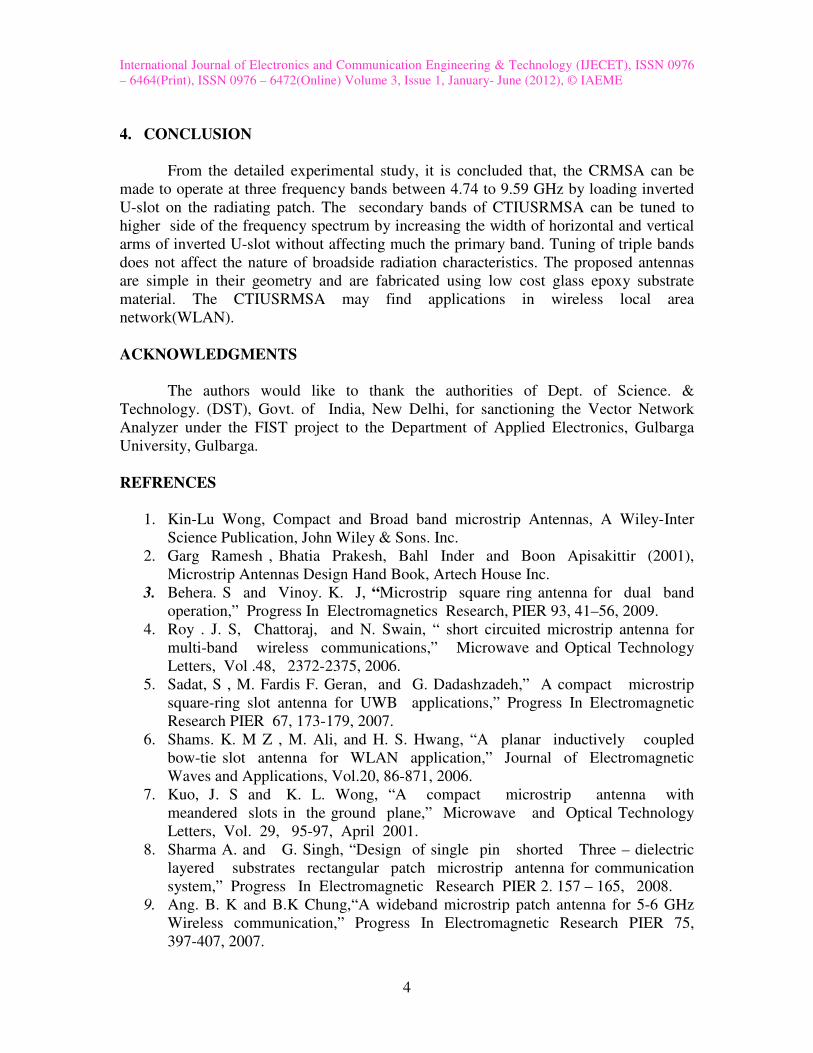
Table 1 Design Parameters of CRMSA and CTIUSRMSA
Antenna
Parameters
Dimensions
in cm
Antenna
Parameters
Dimensions
in cm
W 2.66 Lh λ0/85
Wf 0.32 Lv λ0/42
Wt 0.06 Xd 0.8
L 2.04 Yd 0.2
Lf 2.18 A 5
Lt 1.09 B 8
International Journal of Electronics and Communication Engineering & Technology (IJECET), ISSN 0976
– 6464(Print), ISSN 0976 – 6472(Online) Volume 3, Issue 1, January- June (2012), © IAEME
6
Figure 1 Top view geometry of CRMSA
Figure 2 Top view geometry of CTIUSRMSA
International Journal of Electronics and Communication Engineering & Technology (IJECET), ISSN 0976
– 6464(Print), ISSN 0976 – 6472(Online) Volume 3, Issue 1, January- June (2012), © IAEME
7
Figure 3(a) 3d view of CRMSA
Figure 3(b) 3D view of CTIUSRMSA
Figure 4 Variation of return loss versus frequency of CRMSA
International Journal of Electronics and Communication Engineering & Technology (IJECET), ISSN 0976
– 6464(Print), ISSN 0976 – 6472(Online) Volume 3, Issue 1, January- June (2012), © IAEME
8
Figure 5 Variation of return loss versus frequency of CTIUSRMSA when Uw = 0.2 cm
Figure 6 Variation of return loss versus frequency of CTIUSRMSA when Uw = 0.3 cm
Figure 7 Radiation pattern of CRMSA measured at 3.39 GHz
International Journal of Electronics and Communication Engineering & Technology (IJECET), ISSN 0976
– 6464(Print), ISSN 0976 – 6472(Online) Volume 3, Issue 1, January- June (2012), © IAEME
9
Figure 8 Radiation pattern of CTIUSRMSA when Uw = 0.2 cm measured at 4.74 GHz
Figure 9 Radiation pattern of CTIUSRMSA when Uw = 0.3 cm measured at 4.82GHz