Embed Size (px)
Citation preview

8/8/2019 craniron
http://slidepdf.com/reader/full/craniron 1/52
® Iron Valves
General Data ................................................................................................................................ 2
Materials....................................................................................................................................... 3Ratings ......................................................................................................................................... 4
Pressure/Temperature Ratings .................................................................................................... 4Technical Data............................................................................................................................ 50Installation Recommendations ................................................................................................... 51
Crane also manufactures bronze ball valves, iron wafer and lug butterfly valves, and bronze gate,
globe, and check valves. Brochures and catalogs are available on request.
Index
Iron Valve Selection Guide & Figure Number Index
Pressure Stem: Body/Trim Bonnet/Cap: End CRANE CataloClass RS or NRS IBBM, Al, 3Ni, 2NR BB,TB, Clamp Connections Disc Figure No. Page N
Iron Body Gate Valves - Descriptions and Features on Page 5
125 NRS IBBM BB THD SW 460 6
125 NRS IBBM BB FLG SW 461 7125 NRS Al BB FLG 473 8125 RS, OS&Y IBBM BB THD 464 1 ⁄ 2 9125 RS, OS&Y IBBM (Steel Stem) BB FLG 465 10125 RS, OS&Y IBBM BB FLG 465 1 ⁄ 2 11125 RS, OS&Y Al BB FLG 475 1 ⁄ 2 12175 CWP (UL/FM) RS, OS&Y IBBM BB FLG 467 13125/150 RS Al - Mall. Iron Clamp THD 488 14125/150 RS Al - Mall. Iron Clamp FLG 488 1 ⁄ 2 15125/150 RS IBBM Mall. Iron Clamp THD 490 16150/150 RS IBBM Mall. Iron Clamp FLG 490 1 ⁄ 2 17125 RS, OS&Y Al - Mall. Iron Clamp THD 484 1 ⁄ 2 18125 RS, OS&Y Al - Mall. Iron Clamp FLG 485 1 ⁄ 2 19125 RS, OS&Y IBBM Mall. Iron Clamp THD 486 1 ⁄ 2 20125 RS, OS&Y IBBM Mall. Iron Clamp FLG 487 1 ⁄ 2 21225 CWP RS/OS&Y 2NR Clamp THD 1670 22
200 CWP RS, OS&Y 2NR Clamp FLG 1671 23125 RS, OS&Y 3Ni BB FLG 14477 24250 NRS IBBM BB FLG 3E 25250 RS, OS&Y IBBM BB FLG 7E 26250 RS, OS&Y IBBM BB FLG 7 1 ⁄ 2 E 27
Iron Body Globe Valves - Descriptions and Features on Page 28
125 RS, OS&Y IBBM BB FLG BRZ 351 29250 RS, OS&Y IBBM BB FLG BRZ 21E 30300 RS Al - Mall. Iron UB THD Al 254XR 31
Iron Body Angle Valves
125 RS, OS&Y IBBM BB FLG BRZ 353 32
Iron Body Swing Check Valves - Descriptions and Features on Page 33
125 IBBM BC THD BRZ 372 34125 IBBM BC FLG BRZ 373 35125 IBBM BC FLG Buna-N 373RS 36
125 Al BC FLG Iron 373 1 ⁄ 2 37125 w/outside IBBM BC FLG BRZ 383 38lever & weight175 CWP (UL/FM) IBBM BC FLG BRZ 375 39125 3Ni BC FLG SS 14493 40250 IBBM BC FLG BRZ 39E 41300 Y-Pattern Al - Mall. Iron SC THD Iron 246 1 ⁄ 2 42
Iron Body Tilting Disc Check Valves
125 IBBM FLG 23 43125 Al FLG 24 44250 IBBM FLG 223 45250 Al FLG 224 46
Iron Body Stop Check Valves
250 (Straight flow) RS, OS&Y IBBM BB FLG BRZ 28E 47250 (90° Angle flow) RS, OS&Y IBBM BB FLG BRZ 30E 48

8/8/2019 craniron
http://slidepdf.com/reader/full/craniron 2/52
®
-2- UPDATED 10-2001
General Data
Advanced manufacturing techniques and equipment, a continuing program of engineering research and product
development, skilled craftsman, and over twelve decades of experience in flow control are behind the qualityand dependability built into every Crane product.
Crane valves are suitable for liquid working pressures specified on catalog pages only when used in hydraulicinstallations in which shock is absent or negligible. The sudden closure of a valve in a hydraulic system causesthe body of liquid, which may be moving at a rate generally in excess of one foot per second, to stopinstantaneously. As liquids are relatively incompressible, the sudden cessation of f low effects a rise in pressureconsiderably greater than the static working pressure. This pressure increase is termed “SHOCK” and may, insome cases, be sufficient to cause valves or piping to fail.
Pressure increase due to shock is not dependent upon the working pressure in the system but upon the velocityat which the liquid is flowing. This pressure surge, or shock, severely limits design velocities...a fact readilyunderstandable if it is remembered that pressure rise resulting from arrest of flow may be as high as 60 psi foreach foot per second initial velocity. For example, installations of 100 psi and 1000 psi working pressures, with
the same initial velocity of 10 feet per second, will be subject to the same increase in pressure (approximately600 psi) due to instantaneous closure of a valve.
Shock generally prevails in lines equipped with check or quick-closing valves, or in lines supplied by reciprocatingpumps. It may also be produced, top a lesser degree, by rapid closure of gate and globe valves. Therefore, careshould be exercised when closing valves installed in liquid lines.
Where shock is likely to occur, the maximum shock pressure should be added to the working pressure of the lineto determine working pressure of products in the line...also, hydraulic installations should be equipped with airchambers or other types of shock absorbers to eliminate, as much as possible, increase in pressure due to shock.
Iron valves described in this section meet or exceed the MSS SP-82, MSS SP-70, MSS SP-71 and MSS SP-85specifications for testing.
The selection of materials for components of Crane valves is based upon expert metallurgical, engineering,foundry and fabrication knowledge as well as on many years of usage experience. Considerations affectingmaterials of parts which come in contact with the conveyed fluid include pressure, temperature and chemicalcomposition of the fluid. The materials of moving parts that are subject to rubbing contact are selected on thebasis of their resistance to wear, corrosion, seizing or galling, and on their frictional characteristics.
Utilization of materials to their full capability is assured by the use of stress analysis techniques that includeextensive laboratory testing as well as the application of analytical theory. Stress levels for all materials used aremaintained within the levels established by applicable codes, standards and specifications.
This catalog shows equivalent metric values to the customary imperial units. The “soft” conversion was arrivedat by following MSS SP-86 guidelines.
Illustrations – Catalogue illustrations are representative of a certain size of each line of product but do notnecessarily represent all sizes in all details.
Material & Design – We reserve the right to institute changes in materials, designs, dimensions and specificationswithout notice in keeping with our policy of continuing product development.
Weights – shown are approximate and are not guaranteed. They represent the average weight of Crane ‘Valves’products as made from patterns in use at time weights were complied.
Hydrostatic and Shock Working Pressures
Testing
Materials
Metrication
Illustrations , Weights and Material & Designs
8/8/2019 craniron
http://slidepdf.com/reader/full/craniron 3/52
®
UPDATED 10-2001
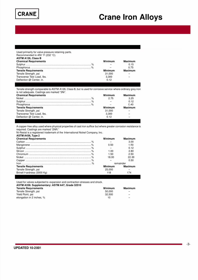
Cast Iron
Used primarily for valve pressure retaining parts.Recommended to 450 °F (232 °C).ASTM A126, Class BChemical Requirements Minimum MaximumSulphur .........................................................................................% – 0.15Phosphorus . .................................................................................% – 0.75Tensile Requirements Minimum MaximumTensile Strength, psi 31,000 – Transverse Test Load, lbs. 3,300 – Deflection @ Center, in. 0.12
Tensile strength comparable to ASTM A126, Class B, but is used for corrosive service where ordinary grey ironis not adequate. Castings are marked “3Ni”.Chemical Requirements Minimum Maximum
Nickel ...........................................................................................% 2.75 3.25Sulphur .........................................................................................% – 0.12Phosphorus . .................................................................................% – 0.40Tensile Requirements Minimum MaximumTensile Strength, psi 31,000 – Transverse Test Load, lbs. 3,300 – Deflection @ Center, in. 0.12 –
NI –Resist Iron
A copper-free alloy used where physical properties of cast iron suffice but where greater corrosion resistance isrequired. Castings are marked “2NR.”Ni-Resist is a registered trademark of the International Nickel Company, Inc.ASTM A436, Type 2Chemical Requirements Minimum MaximumCarbon .........................................................................................% – 3.00Manganese ..................................................................................% 0.50 1.50
Sulphur .........................................................................................% – 0.12Silicon ..........................................................................................% 1.00 2.80Chromium ....................................................................................% 1.50 2.50Nickel . .. ... ... .. ... .. ... ... .. ... .. ... ... .. ... .. ... ... .. ... .. ... ... .. ... ... .. ... .. ... ... .. ... .. ..% 18.00 22.00Copper .........................................................................................% – 0.50Iron ...............................................................................................% remainderTensile Requirements Minimum MaximumTensile Strength, psi 25,000 – Brinell Hardness (3000 Kg) 118 174
Malleable Iron
Used for valves subjected to expansion and contraction stresses and shock.ASTM A338. Supplementary: ASTM A47, Grade 32510Tensile Requirements Minimum MaximumTensile Strength, psi 50,000 – Yield Point, psi 32,500 – elongation in 2 inches, % 10 –
Crane Iron Alloys
3% Nickel Iron

8/8/2019 craniron
http://slidepdf.com/reader/full/craniron 4/52
®
-4- UPDATED 10-2001
U.S. Customary Units
Class 125 250
Non-Shock-PSI
Temp. °F NPS NPS NPS NPS NPS
2"-12" 14"-24" 30"-48" 2"-12" 14"-24"
-20 to 150 200 150 150 500 300
200 190 135 115 460 280
225 180 130 100 440 270
250 175 125 85 415 260
275 170 120 65 395 250
300 165 110 50 375 240
325 155 105 – 355 230350 150 100 – 335 220
375 145 – – 315 210
400 140 – – 290 200
425 130 – – 270 –
450 125 – – 250 –
Iron Valve Ratings
Introduction to Rating
The pressure-temperature ratings shown below apply to class 125 and 250 iron valves covered
in this catalog.
A. Ratings for Class 125 and 250 iron valves are indicated on the relevant catalog page inthis manner:
... PSI Steam, Basic Rating: i.e.: is the nominal steam rated pressure of the valve.
...Cold Working Pressure: where “Cold Working Pressure” is the maximum rated pressureof the valve at a temperature up to 150 °F (65 °C).
The full range of allowable pressure and temperature is determined by referring to the
main pressure-temperature chart below.
B. Ratings for iron valves falling outside Class 125 and 250 are indicated in various ways onthe relevant catalog page.
All ratings represent the maximum allowable non-shock pressure at the indicated temperature.
If the temperature is different from indicated, the allowable pressure may be interpolated.
The operating temperature of the valve is considered as the temperature of the mediaflowing through it. This temperature must not exceed the maximum allowable temperature
as stated in the pressure-temperature chart below.
Pressure-Temperature Ratings
Crane Cast Iron Gate, Globe, Angle and Check Valves
Metric Units
Class 125 250
Non-Shock-kPa
Temp. °C NPS NPS NPS NPS NPS
2"-12" 14"-24" 30"-48" 2"-12" 14"-24"
-29 to 66 1380 1030 1030 3480 2070
90 1310 930 790 3170 1930
110 1240 900 670 3030 1860
120 1210 860 570 2860 1790
140 1170 830 450 2720 1720
150 1140 760 340 2590 1650
160 1070 720 – 2450 1590180 1030 690 – 2310 1520
190 1000 – – 2170 1450
200 970 – – 2000 1380
220 900 – – 1860 –
230 860 – – 1720 –
Manufacturers Standardization Society (MSS)
Standard Practice SP-70, SP-71, SP-85

8/8/2019 craniron
http://slidepdf.com/reader/full/craniron 5/52
®
UPDATED 10-2001
Iron Gate Valve Features
Crane gate valves offer the ultimate independable service wherever minimum
pressure drop is important. They serve as
efficient stop valves with fluid flow in eitherdirection.
The straight through design offers little
resistance to flow and reduces pressuredrop to a minimum. A disc actuated by a
stem and handwheel that moves up anddown at right angles to the path of flow,
and seats against two seat faces to shutoff flow.
Gate valves are best for services that
require infrequent valve operation, andwhere disc is kept either fully opened or
closed. They are not recommended for
throttling. With the usual type of gate valve,close flow regulation is impossible. Velocity
of flow against a partly opened disc maycause vibration and chattering and result
in damage to the seating surfaces. Also,when throttled, the disc is subjected to
severe wire-drawing erosive effects.
Each valve in this section is classified by
its pressure rating. All valves, except clampgate valves, designated as Class 125 and
250 comply with MSS SP-70 StandardPractice.
Bronze trim valves are recommended for
steam, water, air and non-corrosive oil orgas. All have bronze screwed-in seat rings
and the discs are solid bronze in sizes 3"(80 mm) and smaller. In larger sizes,
bronze rings are rolled into cast iron discs.
All-iron valves have integral seats, some
valves have screwed in seat rings (discsare cast iron) and nickel-plated steel
stems. They are recommended for oil, gas,
gasoline, or fluids that corrode bronze butnot iron or steel.
Features
Face-to-Face Dimensions of flanged endvalves comply with MSS SP-70, conform
to ANSI/ASME B16.10 in their pressureclass.
Flanged End Valves adhere to ASME
Specification B16.1 for their pressureclass.
Body and Bonnet Components are cast
with rigorous control to ASTM A126 ClassB Specification for cast-iron. Malleable
iron, Ni-resist and 3% nickel iron are alsoavailable.
Handwheels are furnished on all valves.
Manual gear, hydraulic or motor operatorsand chainwheels can be supplied when
specified.
Backseating - Rising stem valves areequipped with backseats. It is recom-
mended that the backseat be used as ameans for determining the full open valve
position. For normal operation in the oposition, the stem should be backed of
that the backseat is not in contact. Tpermits the stem packing to assume its
tended sealing function and not con
unsatisfactory stem packing. In the evof stem packing leakage, the backseat
be used to stop stem leakage until circstances permit a system shutdown
time for packing replacement. Stem pa
ing replacement with the valve under psure and backseated represents a haz
and should not be undertaken. The hard is magnified as fluid pressure or t
perature increases or when the fluitoxic.
Solid Wedge Gate Valve Discs -strong, simple, single piece design long disc guides is a proven performe
all service conditions, particularly suita
for conditions of severe turbulence stem vibration. Seat and disc surfaces
accurately machined and tapered for soff without undue strain.
Threaded End Valves have precision
threads in accordance with ANSI/ASB1.20.1.
Crane Iron Gate Valves have
identification tag which indicates the v
catalog number and other pertinent datprovides easy and accurate field refere
Handwheel
Handwheel nut
Bonnet
Stem
Gland bolt nut
Gland
Yoke sleeve
Packing
Bonnet bolt
Bonnet gasketBonnet nut
Body
Disc
Disc seat ring
Body seat ring
Handwhee
Handwhee
Gland boltStem
Gland
PackingStuffing boStuffingbox gasket
Bonnet
Bonnet bo
Bonnet nu
Bonnet gas
Disc
Body seat
Body
Disc seat r
Handwheel nutHandwheel
Gland
Packing nutPacking
Stem
Upper bonnet
Stem threadbushing
Lower bonnet
Body seat ring
Disc
Disc
Clamp
Clamp Gate O.S. & Y. Gate NRS Gate

8/8/2019 craniron
http://slidepdf.com/reader/full/craniron 6/52
®
-6- UPDATED 10-2001
Principal Parts & Materials
Fig. No. Size Stem Seating End Conn.
460 2" - 4" Bronze Bronze Threaded
Dimensions and WeightsInches (millimeters) - pounds (kilograms)
Valves 2 2 1/2 3 4(50) (65) (80) (100)
A 5.38 6.62 7.00 8.00(137) (168) (178) (203)
B 11.31 12.40 13.25 16.31(287) (315) (337) (414)
C 8.00 8.00 8.00 10.00(203) (203) (203) (254)
Wt. 25 31 44 71(11.3) (14.0) (20.0) (32.2)
B
A
C
Iron Body Gate Valve
Class 125 • Non-Rising Stem
Figure 460
Features• Tapered Solid Wedge Disc• Body Guide Ribs
• Renewable Bronze Seat Rings• Stem with ACME Double Threads
• Non-Asbestos Packing and Gaskets• MSS-SP-70 Type 1 and MSS-SP-25
• ANSI/ASME B1.20.1
For more detailed features,
refer to page 5.
Figure 460Threaded with Bronze Trim
Size Range:2 through 4 inches
Working Pressures Non-Shock125 psi Steam, Basic Rating
200 psi Cold Working Pressure

8/8/2019 craniron
http://slidepdf.com/reader/full/craniron 7/52
®
UPDATED 10-2001
Principal Parts & Materials
Fig. No. Size Stem Seating End Conn.
461 2" - 30" Bronze Bronze Flanged
Dimensions and WeightsInches (millimeters) - pounds (kilograms)
Valves 2 2 1/2 3 4 5 6 8 10 12 14 16 18 20 24 30(50) (65) (80) (100) (125) (150) (200) (250) (300) (350) (400) (450) (500) (600) (75
A 7.00 7.50 8.00 9.00 10.00 10.50 11.50 13.00 14.00 15.00 16.00 17.00 18.00 20.00 24.(178) (191) (203) (229) (254) (267) (292) (330) (356) (381) (406) (432) (457) (508) (61
B 11.31 12.40 13.25 16.31 18.00 20.69 24.12 33.00 36.50 40.50 46.62 50.75 56.12 64.00 86.(287) (315) (337) (414) (457) (526) (613) (838) (927) (1029) (1184) (1289) (1425) (1625) (220
C 8.00 8.00 8.00 10.00 10.00 12.00 14.00 20.00 20.00 20.00 22.00 22.00 24.00 30.00 30.(203) (203) (203) (254) (254) (305) (356) (508) (508) (508) (559) (559) (610) (762) (76
Wt. 30 40 56 90 126 152 260 475 680 968 1350 1701 2188 3150 600
(13.6) (18.1) (25.4) (41.0) (57.2) (69.0) (118) (215) (308) (439) (613) (772) (994) (1430) (272
Features• Tapered Solid Wedge Disc• Body Guide Ribs
• Renewable Bronze Seat Rings• Stem provided with ACME Double
Threads for valves 24" and smaller;ACME Single Thread for 30" valves.
• Non-Asbestos Packing and Gaskets• MSS-SP-70 Type 1 and MSS-SP-25• ANSI/ASME B16.10, ANSI/ASME
B16.1,• Valves can be equipped with
by-passes when specified.
For more detailed features,refer to page 5.
Figure 461Flanged with Bronze Trim
Size Range:2 through 30 inches
Working Pressures Non-Shock2" – 12"
125 psi Steam, Basic Rating
200 psi Cold Working Pressure14" – 24"
100 psi Steam, Basic Rating150 psi Cold Working Pressure
30"
50 psi Steam, Basic Rating150 psi Cold Working Pressure
Iron Body Gate Valve
Class 125 • Non-Rising Stem
Figure 46
B
A
C

8/8/2019 craniron
http://slidepdf.com/reader/full/craniron 8/52
®
-8- UPDATED 10-2001
Principal Parts & MaterialsFig. No. Size Stem Seating End Conn.
473 2" - 8" Steel Iron FlangedNickel plated
Dimensions and WeightsInches (millimeters) - pounds (kilograms)
Valves 2 2 1/2 3 4 5 6 8(50) (65) (80) (100) (125) (150) (200)
A 7.00 7.50 8.00 9.00 10.00 10.50 11.50(178) (191) (203) (229) (254) (267) (292)
B 11.31 12.40 13.25 16.31 18.00 20.69 24.12(287) (315) (337) (414) (457) (526) (613)
C 8.00 8.00 8.00 10.00 10.00 12.00 14.00(203) (203) (203) (254) (254) (305) (356)
Wt. 30 40 56 90 126 152 260(13.6) (18.1) (25.4) (41.0) (57.2) (69.0) (118)
B
A
C
Features• Tapered Solid Wedge Disc• Body Guide Ribs
• Integral Seats• Stem with ACME Double Threads
• Non-Asbestos Packing and Gaskets• MSS-SP-70 Type 1 and MSS SP-25
• ANSI/ASME B16.10, ANSI/ASMEB16.1,
• Valves can be equipped with
by-passes when specified.
For more detailed features,
refer to page 5.
Figure 473Flanged – All Iron
Size Range:2 through 8 inches
Working Pressures Non-Shock200 psi Cold Working Pressure
Iron Body Gate Valve
Class 125 • Non-Rising Stem
Figure 473

8/8/2019 craniron
http://slidepdf.com/reader/full/craniron 9/52
®
UPDATED 10-2001
Principal Parts & Materials
Fig. No. Size Stem Seating End Conn.
464 1 ⁄ 2 2" - 4" Bronze Bronze Threaded
BOp
A
C
Class 125 • Outside Screw & Yoke • Rising Stem
Features• Tapered Solid Wedge Disc• Body Guide Ribs
• Renewable Bronze Seat Rings• Stem with ACME Double Threads
• Non-Asbestos Packing and Gaskets• MSS-SP-70 Type 1 and MSS-SP-25
• ANSI/ASME B1.20.1
For more detailed features,refer to page 5.
Figure 4641
⁄ 2Threaded with Bronze Trim
Size Range:2 through 4 inches
Working Pressures Non-Shock125 psi Steam, Basic Rating
200 psi Cold Working Pressure
Iron Body Gate Valve Figure 464
Dimensions and WeightsInches (millimeters) - pounds (kilograms)
Valves 2 2 1/2 3 4(50) (65) (80) (100)
A 5.38 6.62 7.00 8.00(137) (168) (178) (203)
B 14.75 16.06 17.38 21.44(375) (408) (441) (545)
C 8.00 8.00 8.00 10.00(203) (203) (203) (254
Wt. 25 38 46 77(11.3) (17.2) (20.9) (35.0)

8/8/2019 craniron
http://slidepdf.com/reader/full/craniron 10/52
®
-10- UPDATED 10-2001
Principal Parts & Materials
Fig. No. Size Stem Seating End Conn.
465 2" - 12" Steel Bronze Flanged
Nickel Plated
Dimensions and WeightsInches (millimeters) - pounds (kilograms)
Valves 2 2 1/2 3 4 5 6 8 10 12(50) (65) (80) (100) (125) (150) (200) (250) (300)
A 7.00 7.50 8.00 9.00 10.00 10.50 11.50 13.00 14.00(178) (191) (203) (229) (254) (267) (292) (330) (356)
B 14.75 16.06 17.38 21.44 25.81 30.31 37.75 49.41 56.81(375) (408) (441) (545) (656) (770) (959) (1255) (1443)
C 8.00 8.00 8.00 10.00 10.00 12.00 14.00 18.00 18.00(203) (203) (203) (254) (254) (305) (356) (457) (457)
Wt. 33 47 58 97 125 162 280 502 670(15) (21.3) (26.3) (44.0) (56.7) (73.6) (127.2) (228) (304)
BOpen
A
C
Class 125 • Outside Screw & Yoke • Rising Stem
Features• Tapered Solid Wedge Disc• Body Guide Ribs
• Renewable Bronze Seat Rings• Steel Stem with ACME Double
Threads• Non-Asbestos Packing and Gaskets
• MSS-SP-70 Type 1 and MSS-SP-25• ANSI/ASME B16.10, ANSI/ASME
B16.1,
• Valves can be equipped withby-passes when specified.
For more detailed features,refer to page 5.
Figure 465Flanged with Bronze Seating,
Steel Stem, Nickel Plated
Size Range:2 through 12 inches
Working Pressures Non-Shock
2" – 12"
125 psi Steam, Basic Rating
200 psi Cold Working Pressure
Iron Body Gate ValveFigure 465

8/8/2019 craniron
http://slidepdf.com/reader/full/craniron 11/52
®
-UPDATED 10-2001
Principal Parts & Materials
Fig. No. Size Stem Seating End Conn.
465 1 ⁄ 2 2" - 36" Bronze Bronze Flanged
Dimensions and WeightsInches (millimeters) - pounds (kilograms)
Valves 2 2 1/2 3 4 5 6 8 10 12 14 16 18 20 24 30 36(50) (65) (80) (100) (125) (150) (200) (250) (300) (350) (400) (450) (500) (600) (750) (90
A 7.00 7.50 8.00 9.00 10.00 10.50 11.50 13.00 14.00 15.00 16.00 17.00 18.00 20.00 24.00 28.(178) (191) (203) (229) (254) (267) (292) (330) (356) (381) (406) (432) (457) (508) (610) (71
B 14.75 16.06 17.38 21.44 25.81 30.31 37.75 49.41 56.81 64.88 75.19 82.00 90.19 105.31 129.62 192(375) (408) (441) (545) (656) (770) (959) (1255) (1443) (1648) (1910) (2083) (2291) (2675) (3292) (489
C 8.00 8.00 8.00 10.00 10.00 12.00 14.00 18.00 18.00 20.00 22.00 22.00 24.00 30.00 30.00 30.(203) (203) (203) (254) (254) (305) (356) (457) (457) (508) (559) (559) (610) (762) (762) (76
Wt. 30 47 58 97 125 162 280 502 670 1093 1425 1738 2085 3183 5795 762(13.6) (21.3) (26.3) (44.0) (56.7) (73.6) (127.2) (228) (304) (496) (646) (788) (946) (1444) (2629) (345
Class 125 • Outside Screw & Yoke • Rising Stem
Features• Tapered Solid Wedge Disc• Body Guide Ribs
• Renewable Bronze Seat Rings• Stem provided with ACME Double
Threads for 24" and smaller valves;ACME Single Thread for 30" and 36"
valves.• Non-Asbestos Packing and Gaskets• MSS-SP-70 Type 1 and MSS-SP-25
• ANSI/ASME B16.10, ANSI/ASMEB16.1,
• Valves can be equipped with
by-passes when specified.
For more detailed features,refer to page 5.
Figure 4651
⁄ 2
Flanged with Bronze Trim
Size Range:2 through 36 inches
Working Pressures Non-Shock
2" – 12"
125 psi Steam, Basic Rating
200 psi Cold Working Pressure
14" – 24"
100 psi Steam, Basic Rating
150 psi Cold Working Pressure
30" – 36"50 psi Steam, Basic Rating
150 psi Cold Working Pressure
Iron Body Gate Valve Figure 465
O
A
C

8/8/2019 craniron
http://slidepdf.com/reader/full/craniron 12/52
®
-12- UPDATED 10-2001
Principal Parts & Materials
Fig. No. Size Stem Seating End Conn.
475 1 ⁄ 2 2" - 36" Steel Iron FlangedNickel Plated
Dimensions and WeightsInches (millimeters) - pounds (kilograms)
Valves 2 2 1/2 3 4 5 6 8 10 12 14 16 18 20 24 30 36(50) (65) (80) (100) (125) (150) (200) (250) (300) (350) (400) (450) (500) (600) (750) (900)
A 7.00 7.50 8.00 9.00 10.00 10.50 11.50 13.00 14.00 15.00 16.00 17.00 18.00 20.00 24.00 28.00(178) (191) (203) (229) (254) (267) (292) (330) (356) (381) (406) (432) (457) (508) (610) (711)
B 14.75 16.06 17.38 21.44 25.81 30.31 37.75 49.41 56.81 64.88 75.19 82.00 90.19 105.31 129.62 192.69(375) (408) (441) (545) (656) (770) (959) (1255) (1443) (1648) (1910) (2083) (2291) (2675) (3292) (4894)
C 8.00 8.00 8.00 10.00 10.00 12.00 14.00 18.00 18.00 20.00 22.00 22.00 24.00 30.00 30.00 30.00(203) (203) (203) (254) (254) (305) (356) (457) (457) (508) (559) (559) (610) (762) (762) (762)
Wt. 30 47 58 97 125 162 280 502 670 1093 1425 1738 2085 3183 5795 7622(13.6) (21.3) (26.3) (44.0) (56.7) (73.6) (127.2) (228) (304) (496) (646) (788) (946) (1444) (2629) (3457)
BOpen
A
C
Class 125 • Outside Screw & Yoke • Rising Stem
Features• Tapered Solid Wedge Disc• Body Guide Ribs• 2"-8" Integral Seats, 10" and larger
Renewable Cast Iron Seat Rings• Stem provided with ACME Double
Threads for 24" and smaller valves;ACME Single Thread for 30" and 36"
valves.• Non-Asbestos Packing and Gaskets• MSS-SP-70 Type 1 and MSS-SP-25
• ANSI/ASME B16.10, ANSI/ASMEB16.1
• Valves can be equipped withby-passes when specified.
For more detailed features,refer to page 5.
Figure 4751
⁄ 2
Flanged – All Iron
Size Range:2 through 36 inches
Working Pressures Non-Shock
2" – 12"
200 psi Cold Working Pressure
14" – 36"
150 psi Cold Working Pressure
Iron Body Gate ValveFigure 475 1 ⁄ 2

8/8/2019 craniron
http://slidepdf.com/reader/full/craniron 13/52
®
-UPDATED 10-2001
Principal Parts & Materials
Fig. No. Stem Seating End Conn.
467 Bronze Bronze Flanged
Dimensions and WeightsInches (millimeters) - pounds (kilograms)
Valves 2 1/2 3 4 6 8 10 12(65) (80) (100) (150) (200) (250) (300)
A 7.50 8.00 9.00 10.50 11.50 13.00 14.00(191) (203) (229) (267) (292) (330) (356)
B 16.06 17.38 21.44 30.31 37.75 49.41 56.81(408) (441) (545) (770) (959) (1,255) (1,443)
C 8.00 8.00 10.00 12.00 14.00 18.00 18.00(203) (203) (254) (305) (356) (457) (457)
Wt. 47 58 97 162 280 502 670(21.3) (26.3) (44.0) (73.5) (127.0) (227.7) (303.9)
O
A
C
175 CWP • Outside Screw & Yoke • UL/ULC/FM Listed
Figure 46
Features• Designed expressly for Fire ProtectionService. Listed by Underwriter's Labor-
atories Inc., Underwriter's Labor-atories of Canada and Factory Mutual
Research Corp.• Stem with ACME Double Threads
• Tapered Solid Wedge Disc• Flanged Ends• Non-Asbestos Packing and Gaskets
• Renewable Bronze Seat Rings• ANSI/ASME B16.10, ANSIASME
B16.1
• UL 262 Standard
For more detailed features,refer to page 5.
Figure 467Size Range:2-1/2 through 12 inches
Working Pressure Non-Shock175 psi Cold Working Pressure
Iron Body Gate Valve

8/8/2019 craniron
http://slidepdf.com/reader/full/craniron 14/52
®
-14- UPDATED 10-2001
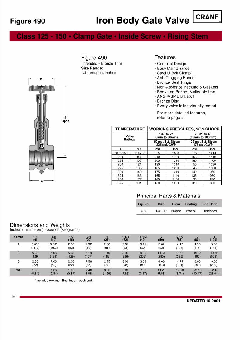
Class 125 - 150 • Clamp Gate • Inside Screw • Rising Stem
Figure 488
Features• Compact Design• Easy Maintenance
• Steel U-Bolt Clamp• Anti-Clogging Bonnet
• Integral Seats• Malleable Iron Disc
• Nickel Plated Steel Stem• Non-Asbestos Packing & Gaskets• Body and Bonnet Malleable Iron
• ANSI/ASME B1.20.1• Every valve is individually tested
For more detailed features,refer to page 5.
Figure 488Threaded - All Iron
Size Range:1/4 through 4 inches
Iron Body Gate Valve
Principal Parts & Materials
Fig. No. Size Stem Seating End Conn.
488 1/4" - 4" Steel Iron ThreadedNickel Plated
TEMPERATURE WORKING PRESSURES, NON-SHOCK
1/4" - 2" 2 1/2" to 4"(6mm to 50mm) (65mm to 100mm)
225 psi, CWP 175 psi, CWP
°F °C PSI kPa PSI kPa
-20 to 150 -30 to 65 225 1550 175 1210200 93 210 1450 165 1140225 107 200 1380 160 1100250 121 190 1310 150 1030275 135 185 1280 145 1000300 149 175 1210 140 970325 163 165 1140 135 930
350 177 160 1100 125 860375 191 150 1030 120 830
ValveRatings
C
BOpen
A
Dimensions and WeightsInches (millimeters) - pounds (kilograms)
Valves 1/4 3/8 1/2 3/4 1 1 1/4 1 1/2 2 2 1/2 3 4(6) (10) (15) (20) (25) (32) (40) (50) (65) (80) (100)
A 3.00* 3.00* 2.06 2.32 2.56 2.87 3.15 3.62 4.12 4.56 5.56(76.2) (76.2) (52) (59) (65) (73) (80) (92) (105) (116) (141)
B 5.08 5.08 5.08 6.19 7.40 8.90 9.96 11.61 12.91 15.35 19.76(129) (129) (129) (157) (188) (226) (253) (295) (328) (390) (502)
C 2.06 2.06 2.06 2.56 2.75 3.06 3.62 4.06 4.75 6.00 9.00(52) (52) (52) (65) (70) (78) (92) (103) (121) (152) (229)
Wt. 1.86 1.86 1.86 2.40 3.50 5.80 7.00 11.20 19.20 23.10 52.10(0.84) (0.84) (0.84) (1.09) (1.59) (2.63) (3.17) (5.08) (8.71) (10.47) (23.61)
*Includes Hexagon Bushings in each end.

8/8/2019 craniron
http://slidepdf.com/reader/full/craniron 15/52
®
-UPDATED 10-2001
Class 125 • Clamp Gate • Inside Screw • Rising Stem
Figure 488
Features• Compact Design• Easy Maintenance
• Steel U-Bolt Clamp• Anti-Clogging Bonnet
• Integral Seats• Malleable Iron Disc
• Nickel Plated Steel Stem• Non-Asbestos Packing & Gaskets• Body and Bonnet Malleable Iron
• ANSI/ASME B16.1• Every valve is individually tested
For more detailed features,refer to page 5.
Figure 4881
⁄ 2Flanged - All Iron
Size Range:1 through 4 inches
Iron Body Gate Valve
TEMPERATURE WORKING PRESSURES, NON-SHOCK
1" to 2" 2 1/2" to 4"(25mm to 50mm) (65mm to 100mm)
200 psi, CWP 175 psi, CWP
°F °C PSI kPa PSI kPa-20 to 150 -30 to 65 200 1380 175 1210
200 93 185 1280 165 1140225 107 175 1210 160 1100250 121 165 1140 150 1030275 135 155 1070 145 1000300 149 145 1000 140 970325 163 135 930 135 930
350 177 130 900 125 860375 191 120 830 120 830
ValveRatings
C
BOpen
A
Principal Parts & Materials
Fig. No. Size Stem Seating End Conn.
488 1 ⁄ 2 1" - 4" Steel Iron FlangedNickel Plated
Dimensions and WeightsInches (millimeters) - pounds (kilograms)
Valves 1 1 1/2 2 2 1/2 3 4(25) (40) (50) (65) (80) (100)
A 3.19 3.74 4.25 4.94 5.06 6.75(81) (95) (108) (125) (129) (172)
B 7.40 9.96 11.61 12.91 15.35 19.76(188) (253) (295) (328) (390) (502)
C 2.75 3.62 4.06 4.75 6.00 9.00(70) (92) (103) (121) (152) (229)
Wt. 5.50 10.40 14.30 22.00 32.0 60.0(2.49) (4.71) (6.48) (9.97) (14.50) (27.19)
8/8/2019 craniron
http://slidepdf.com/reader/full/craniron 16/52
®
-16- UPDATED 10-2001
Principal Parts & Materials
Fig. No. Size Stem Seating End Conn.
490 1/4" - 4" Bronze Bronze Threaded
Dimensions and WeightsInches (millimeters) - pounds (kilograms)
Valves 1/4 3/8 1/2 3/4 1 1 1/4 1 1/2 2 2 1/2 3 4(6) (10) (15) (20) (25) (32) (40) (50) (65) (80) (100)
A 3.00* 3.00* 2.06 2.32 2.56 2.87 3.15 3.62 4.12 4.56 5.56(76.2) (76.2) (52) (59) (65) (73) (80) (92) (105) (116) (141)
B 5.08 5.08 5.08 6.19 7.40 8.90 9.96 11.61 12.91 15.35 19.76(129) (129) (129) (157) (188) (226) (253) (295) (328) (390) (502)
C 2.06 2.06 2.06 2.56 2.75 3.06 3.62 4.06 4.75 6.00 9.00(52) (52) (52) (65) (70) (78) (92) (103) (121) (152) (229)
Wt. 1.86 1.86 1.86 2.40 3.50 5.80 7.00 11.20 19.20 23.10 52.10(0.84) (0.84) (0.84) (1.08) (1.59) (2.63) (3.17) (5.08) (8.71) (10.47) (23.61)
*Includes Hexagon Bushings in each end.
Class 125 - 150 • Clamp Gate • Inside Screw • Rising Stem
Figure 490
Features• Compact Design• Easy Maintenance
• Steel U-Bolt Clamp• Anti-Clogging Bonnet
• Bronze Seat Rings• Non-Asbestos Packing & Gaskets
• Body and Bonnet Malleable Iron• ANSI/ASME B1.20.1• Bronze Disc
• Every valve is individually tested
For more detailed features,
refer to page 5.
Figure 490Threaded - Bronze Trim
Size Range:1/4 through 4 inches
Iron Body Gate Valve
TEMPERATURE WORKING PRESSURES, NON-SHOCK
1/4" to 2" 2 1/2" to 4"(6mm to 50mm) (65mm to 100mm)
150 psi, Sat. Steam 125 psi, Sat. Steam225 psi, CWP 175 psi, CWP
°F °C PSI kPa PSI kPa
-20 to 150 -30 to 65 225 1550 175 1210200 93 210 1450 165 1140225 107 200 1380 160 1100250 121 190 1310 150 1030275 135 185 1280 145 1000300 149 175 1210 140 970325 163 165 1140 135 930
350 177 160 1100 125 860375 191 150 1030 120 830
ValveRatings
C
BOpen
A

8/8/2019 craniron
http://slidepdf.com/reader/full/craniron 17/52
®
-UPDATED 10-2001
Principal Parts & Materials
Fig. No. Size Stem Seating End Conn.
490 1 ⁄ 2 1 1/2" - 4" Bronze Bronze Flanged
Dimensions and WeightsInches (millimeters) - pounds (kilograms)
Valves 1 1/2 2 2 1/2 3 4(40) (50) (65) (80) (100)
A 3.74 4.25 4.94 5.06 6.75(95) (108) (125) (129) (172)
B 9.96 11.61 12.91 15.35 19.76(253) (295) (328) (390) (502)
C 3.62 4.06 4.75 6.00 9.00(92) (103) (121) (152) (229)
Wt. 10.40 14.30 22.00 32.0 60.0(4.17) (6.48) (9.97) (14.50) (27.19)
Class 125 • Clamp Gate • Inside Screw • Rising Stem
Figure 490
Features• Compact Design• Easy Maintenance
• Steel U-Bolt Clamp• Anti-Clogging Bonnet
• Bronze Seat Rings• Non-Asbestos Packing & Gaskets• Body and Bonnet Malleable Iron
• ANSI/ASME B16.1• Bronze Disc
• Every valve is individually tested
For more detailed features,
refer to page 5.
Figure 4901
⁄ 2Flanged - Bronze Trim
Size Range:1-1/2 through 4 inches
Iron Body Gate Valve
TEMPERATURE WORKING PRESSURES, NON-SHOCK
1 1/2" to 2" 2 1/2" to 4"(40mm to 50mm) (65mm to 100mm)
125 psi, Sat. Steam 125 psi, Sat. Steam200 psi, CWP 175 psi, CWP
°F °C PSI kPa PSI kPa
-20 to 150 -30 to 65 200 1380 175 1210200 93 185 1280 165 1140225 107 175 1210 160 1100250 121 165 1140 150 1030275 135 155 1070 145 1000300 149 145 1000 140 970325 163 135 930 135 930
350 177 130 900 125 860375 191 120 830 120 830
ValveRatings
C
B
Open
A

8/8/2019 craniron
http://slidepdf.com/reader/full/craniron 18/52
®
-18- UPDATED 10-2001
Principal Parts & Materials
Fig. No. Size Stem Seating End Conn.
484 1 ⁄ 2 1/2" - 3" Steel Iron ThreadedNickel Plated
Dimensions and WeightsInches (millimeters) - pounds (kilograms)
Valves 1/2 3/4 1 1 1/4 1 1/2 2 2 1/2 3(15) (20) (25) (32) (40) (50) (65) (80)
A 2.06 2.32 2.56 2.87 3.15 3.62 4.12 4.56(52) (59 ) (65) (73) (80) (92) (105) (116)
B 6.75 7.52 9.25 10.25 12.24 14.50 16.50 19.00(171) (191) (235) (260) (311) (368) (419) (483)
C 2.56 2.56 2.75 3.06 3.62 4.06 4.75 6.00(65) (65) (70) (78) (92) (103) (121) (152)
Wt. 2.0 4.0 5.0 6.0 9.5 13.5 20.5 29.5(0.91) (1.81) (2.26) (2.72) (4.31) (6.12) (9.30) (13.38)
Class 125 • Outside Screw & Yoke • Threaded Ends
Figure 484 1 ⁄ 2
Features• Compact Design
• Easy Maintenance• Steel U-Bolt Clamp• Integral Seats
• Malleable Iron Disc• Nickel Plated Steel Stem
• Non-Asbestos Packing & Gasket• Body and Bonnet Malleable Iron
• ANSI/ASME B1.20.1• Every valve is individually tested
For more detailed features,
refer to page 5.
Figure 4841
⁄ 2Threaded - All Iron
Size Range:1/2 through 3 inches
Clamp Gate Valve
C
B
A
TEMPERATURE WORKING PRESSURES, NON-SHOCK
1/2" to 2" 2 1/2" to 3"(12mm to 50mm) (65mm to 75mm)
225 psi, CWP 175 psi, CWP
°F °C PSI kPa PSI kPa
-20 to 150 -30 to 65 225 1550 175 1210200 93 210 1450 165 1140225 107 200 1380 160 1100250 121 190 1310 150 1030275 135 185 1280 145 1000300 149 175 1210 140 970325 163 165 1140 135 930
350 177 160 1100 125 860375 191 150 1030 120 830
ValveRatings

8/8/2019 craniron
http://slidepdf.com/reader/full/craniron 19/52
®
-UPDATED 10-2001
Principal Parts & Materials
Fig. No. Size Stem Seating End Conn.
485 1 ⁄ 2 1-1/2" - 4" Steel Iron FlangedNickel Plated
Dimensions and WeightsInches (millimeters) - pounds (kilograms)
Valves 1 1/2 2 2 1/2 3 4(40) (50) (65) (80) (100)
A 3.74 4.25 4.94 5.06 6.75(95) (108) (125) (129) (171)
B 12.24 14.50 16.50 19.00 24.00(311) (368) (419) (483) (610)
C 3.62 4.06 4.75 6.00 9.00(92) (103) (121) (152) (229)
Wt. 14.5 19.5 31.0 40.0 75.0(6.58) (8.84) (14.06) (18.14) (34.01)
C
B
A
Class 125 • Outside Screw & Yoke • Flanged Ends
Figure 485
Features• Compact Design• Easy Maintenance
• Steel U-Bolt Clamp• Integral Seats
• Malleable Iron Disc• Nickel Plated Steel Stem• Non-Asbestos Packing & Gasket
• Body and Bonnet Malleable Iron• ANSI/ASME B16.1
• Every valve is individually tested
For more detailed features,
refer to page 5.
Figure 4851
⁄ 2Flanged - All Iron
Size Range:1-1/2 through 4 inches
Malleable IronClamp Gate Valve
TEMPERATURE WORKING PRESSURES, NON-SHOCK
1 1/2" to 2" 2 1/2" to 4"(40mm to 50mm) (65mm to 100mm)
200 psi, CWP 175 psi, CWP
°F °C PSI kPa PSI kPa
-20 to 150 -30 to 65 200 1380 175 1210200 93 185 1280 165 1140225 107 175 1210 160 1100250 121 165 1140 150 1030275 135 155 1070 145 1000300 149 145 1000 140 970325 163 135 930 135 930
350 177 130 900 125 860375 191 120 830 120 830
ValveRatings
O

8/8/2019 craniron
http://slidepdf.com/reader/full/craniron 20/52
®
-20- UPDATED 10-2001
Principal Parts & Materials
Fig. No. Size Stem Seating End Conn.
486 1 ⁄ 2 1/2" - 2" Bronze Bronze Threaded
Dimensions and WeightsInches (millimeters) - pounds (kilograms)
Valves 1/2 3/4 1 1 1/4 1 1/2 2(15) (20) (25) (32) (40) (50)
A 2.06 2.32 2.56 2.87 3.15 3.62(52) (59) (65) (73) (80) (91)
B 6.75 7.52 9.25 10.25 12.24 14.50(171) (191) (235) (260) (311) (368)
C 2.56 2.56 2.75 3.06 3.62 4.06(65) (65) (70) (78) (92) (103)
Wt. 2.0 4.0 4.4 7.1 9.5 12.1(0.91) (1.81) (2.00) (3.21) (4.31) (5.49)
Class 125 • Outside Screw & Yoke • Threaded Ends
Figure 486 1 ⁄ 2
Features• Compact Design• Easy Maintenance• Steel U-Bolt Clamp
• Bronze Seat Rings• Bronze Disc
• Non-Asbestos Packing & Gasket• Body and Bonnet Malleable Iron
• ANSI/ASME B1.20.1• Every valve is individually tested
For more detailed features,refer to page 5.
Figure 4861
⁄ 2Threaded - Bronze Trim
Size Range:1/2 through 2 inches
Malleable IronClamp Gate Valve
C
B
A
TEMPERATURE WORKING PRESSURES, NON-SHOCK1/2" to 2"
(12mm to 50mm)
150 psi, Sat. Steam225 psi, CWP
°F °C PSI kPa
-20 to 150 -30 to 65 225 1550200 93 210 1450225 107 200 1380250 121 190 1310275 135 185 1280300 149 175 1210325 163 165 1140
350 177 160 1100375 191 150 1030
ValveRatings
Open

8/8/2019 craniron
http://slidepdf.com/reader/full/craniron 21/52
®
-UPDATED 10-2001
Principal Parts & Materials
Fig. No. Size Stem Seating End Conn.
487 1 ⁄ 2 1-1/2" - 4" Bronze Bronze Flanged
Dimensions and WeightsInches (millimeters) - pounds (kilograms)
Valves 1 1/2 2 2 1/2 3 4(40) (50) (65) (80) (100)
A 3.74 4.25 4.94 5.06 6.75(95) (108) (125) (129) (171)
B 12.24 14.50 16.50 19.00 24.00(311) (368) (419) (485) (510)
C 3.62 4.06 4.75 6.00 9.00(92) (103) (121) (152) (229)
Wt. 13.0 17.0 31.0 40.0 75.0(5.90) (7.71) (14.06) (18.14) (34.01)
C
B
A
Class 125 • Outside Screw & Yoke • Flanged Ends
Figure 487
Features• Compact Design• Easy Maintenance
• Steel U-Bolt Clamp• Bronze Seat Rings
• Bronze Disc• Non-Asbestos Packing & Gasket• Body and Bonnet Malleable Iron
• ANSI/ASME B16.1• Every valve is individually tested
For more detailed features,
refer to page 5.
Figure 4871
⁄ 2Flanged - Bronze Trim
Size Range:1-1/2 through 4 inches
Malleable IronClamp Gate Valve
TEMPERATURE WORKING PRESSURES, NON-SHOCK
1 1/2" to 2" 2 1/2" to 4"(40mm to 50mm) (65mm to 100mm)
125 psi, Sat. Steam 125 psi, Sat. Steam200 psi, CWP 175 psi, CWP
°F °C PSI kPa PSI kPa
-20 to 150 -30 to 65 200 1380 175 1210200 93 185 1280 165 1140225 107 175 1210 160 1100250 121 165 1140 150 1030275 135 155 1070 145 1000300 149 145 1000 140 970325 163 135 930 135 930350 177 130 900 125 860
375 191 120 830 120 830
ValveRatings Open
8/8/2019 craniron
http://slidepdf.com/reader/full/craniron 22/52
®
-22- UPDATED 10-2001
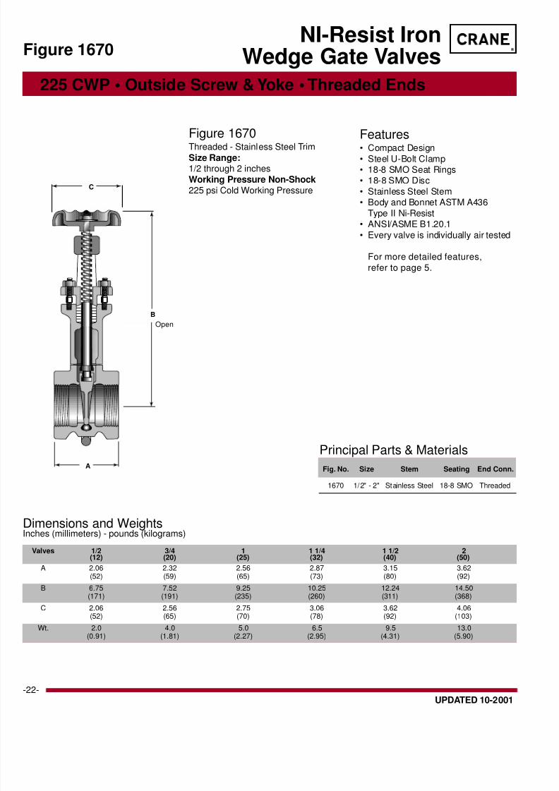
Principal Parts & Materials
Fig. No. Size Stem Seating End Conn.
1670 1/2" - 2" Stainless Steel 18-8 SMO Threaded
Dimensions and WeightsInches (millimeters) - pounds (kilograms)
Valves 1/2 3/4 1 1 1/4 1 1/2 2(12) (20) (25) (32) (40) (50)
A 2.06 2.32 2.56 2.87 3.15 3.62(52) (59) (65) (73) (80) (92)
B 6.75 7.52 9.25 10.25 12.24 14.50(171) (191) (235) (260) (311) (368)
C 2.06 2.56 2.75 3.06 3.62 4.06(52) (65) (70) (78) (92) (103)
Wt. 2.0 4.0 5.0 6.5 9.5 13.0(0.91) (1.81) (2.27) (2.95) (4.31) (5.90)
225 CWP • Outside Screw & Yoke • Threaded Ends
Figure 1670
Features• Compact Design
• Steel U-Bolt Clamp• 18-8 SMO Seat Rings• 18-8 SMO Disc
• Stainless Steel Stem• Body and Bonnet ASTM A436
Type II Ni-Resist• ANSI/ASME B1.20.1
• Every valve is individually air tested
For more detailed features,
refer to page 5.
Figure 1670Threaded - Stainless Steel Trim
Size Range:1/2 through 2 inches
Working Pressure Non-Shock225 psi Cold Working Pressure
NI-Resist IronWedge Gate Valves
C
B
A
Open

8/8/2019 craniron
http://slidepdf.com/reader/full/craniron 23/52
®
-UPDATED 10-2001
Principal Parts & Materials
Fig. No. Size Stem Seating End Conn.
1671 2" - 3" Stainless Steel 18-8 SMO Flanged
Dimensions and WeightsInches (millimeters) - pounds (kilograms)
Valves 2 2 1/2 3( 50) ( 65) ( 80)
A 4.25 4.94 5.06(108) (125) (129)
B 14.50 16.50 19.02(368) (419) (483)
C 4.06 4.75 6.00(103) (121) (152)
Wt. 20 32 41(9.07) (14.51) (18.59)
200 CWP • Outside Screw & Yoke • Flanged Ends
Figure 167
Features• Compact Design
• Steel U-Bolt Clamp• 18-8 SMO Seat Rings
• 18-8 SMO Disc• Stainless Steel Stem• Body and Bonnet ASTM A436
Type II Ni-Resist• ANSI/ASME B16.1
• Every valve is individually air tested
For more detailed features,refer to page 5.
Figure 1671Flanged - Stainless Steel Trim
Size Range:2 through 3 inches
Working Pressure Non-Shock2" 200 psi Cold Working Pressure
2 1/2"-3" 175 psi Cold WorkingPressure
NI-Resist IronWedge Gate Valves
C
B
A
Open
8/8/2019 craniron
http://slidepdf.com/reader/full/craniron 24/52
®
-24- UPDATED 10-2001
BOpen
A
C
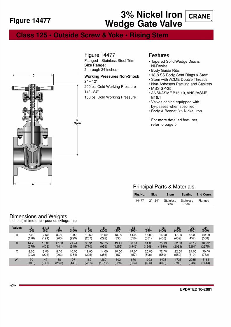
Principal Parts & Materials
Fig. No. Size Stem Seating End Conn.
14477 2" - 24" Stainless Stainless FlangedSteel Steel
Dimensions and WeightsInches (millimeters) - pounds (kilograms)
Valves 2 2 1/2 3 4 6 8 10 12 14 16 18 20 24(50) (65) (80) (100) (150) (200) (250) (300) (350) (400) (450) (500) (600)
A 7.00 7.50 8.00 9.00 10.50 11.50 13.00 14.00 15.00 16.00 17.00 18.00 20.00(178) (191) (203) (229) (267) (292) (330) (356) (381) (406) (432) (457) (508)
B 14.75 16.06 17.38 21.44 30.31 37.75 49.41 56.81 64.88 75.19 82.00 90.19 105.31(375) (408) (441) (545) (770) (959) (1255) (1443) (1648) (1910) (2083) (2291) (2675)
C 8.00 8.00 8.00 10.00 12.00 14.00 18.00 18.00 20.00 22.00 22.00 24.00 30.00(203) (203) (203) (254) (305) (356) (457) (457) (508) (559) (559) (610) (762)
Wt. 30 47 58 97 162 280 502 670 1093 1425 1738 2085 3183(13.6) (21.3) (26.3) (44.0) (73.6) (127.2) (228) (304) (496) (646) (788) (946) (1444)
Class 125 • Outside Screw & Yoke • Rising Stem
Features• Tapered Solid Wedge Disc is
Ni-Resist• Body Guide Ribs
• 18-8 SS Body, Seat Rings & Stem• Stem with ACME Double Threads
• Non-Asbestos Packing and Gaskets• MSS-SP-25• ANSI/ASME B16.10, ANSI/ASME
B16.1• Valves can be equipped with
by-passes when specified• Body & Bonnet 3% Nickel Iron
For more detailed features,refer to page 5.
Figure 14477Flanged - Stainless Steel Trim
Size Range:2 through 24 inches
Working Pressures Non-Shock
2" – 12"
200 psi Cold Working Pressure
14" - 24"
150 psi Cold Working Pressure
3% Nickel IronWedge Gate ValveFigure 14477

8/8/2019 craniron
http://slidepdf.com/reader/full/craniron 25/52
®
-UPDATED 10-2001
A
C
Dimensions and WeightsInches (millimeters) - pounds (kilograms)
Valves 2 2 1/2 3 4 6 8 10 12(50) (65) (80) (100) (150) (200) (250) (300)
A 8.50 9.50 11.12 12.00 15.88 16.50 18.00 19.75(216) (241) (282) (305) (403) (419) (457) (502)
B 11.94 12.94 14.50 17.38 23.00 30.75 36.00 39.75(303) (329) (368) (441) (584) (781) (914) (1010)
C 8.00 8.00 10.00 12.00 16.00 20.00 22.00 24.00(203) (229) (254) (305) (406) (508) (559) (610)
Wt. 47 84 113 175 335 545 961 1300(21) (38) (51) (80) (152) (247) (386) (590)
Principal Parts & Materials
Fig. No. Size Stem Seating End Conn.
3E 2" - 12" Bronze Bronze Flanged
Class 250 • Non-Rising Stem • Flanged Ends
Figure 3
Features• Tapered Solid Wedge Disc• Body Guide Ribs
• Renewable Bronze Seat Rings• Non-Asbestos Packing & Gaskets
• Valves can be equipped with by-passes when specified
• Valves 6" and larger have bossescast into the bodies and bonnets,and can be equipped with taps and
drains to prevent fluids fromaccumulating and possibly causing
damage. Orders must specify
location of taps and drains.• Stem with ACME Double Threads• MSS-SP-70 Type 1 and MSS-SP-25
ANSI/ASME B16.10, ANSI/ASME
B16 .1
For more detailed features,refer to page 5.
Figure 3EFlanged with Bronze Trim
Size Range:2 through 12 inches
Working Pressures Non-Shock
250 psi Steam, Basic Rating
500 psi Cold Working Pressure
Iron Body Gate Valve
8/8/2019 craniron
http://slidepdf.com/reader/full/craniron 26/52
®
-26- UPDATED 10-2001
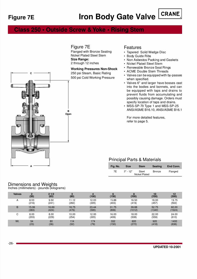
Dimensions and WeightsInches (millimeters) - pounds (kilograms)
Valves 2 2 1/2 3 4 6 8 10 12(50) (65) (80) (100) (150) (200) (250) (300)
A 8.50 9.50 11.12 12.00 15.88 16.50 18.00 19.75(216) (241) (282) (305) (403) (419) (457) (502)
B 15.06 16.69 18.75 23.44 31.75 39.88 52.75 60.00(383) (424) (476) (595) (806) (1012) (1340) (1524)
C 8.00 8.00 10.00 12.00 16.00 18.00 22.00 24.00(203) (229) (254) (305) (406) (508) (559) (610)
Wt. 54 80 114 174 332 600 920 1400(23) (36) (52) (79) (150) (272) (418) (636)
Principal Parts & Materials
Fig. No. Size Stem Seating End Conn.
7E 2" - 12" Steel Bronze FlangedNickel Plated
Class 250 • Outside Screw & Yoke • Rising Stem
Figure 7E
Features• Tapered Solid Wedge Disc
• Body Guide Ribs• Non Asbestos Packing and Gaskets• Nickel Plated Steel Stem
• Renewable Bronze Seat Rings• ACME Double Stem Threads
• Valves can be equipped with by-passeswhen specified.
• Valves 6" and larger have bosses castinto the bodies and bonnets, and canbe equipped with taps and drains to
prevent fluids from accumulating and
possibly causing damage. Orders mustspecify location of taps and drains.
• MSS-SP-70 Type 1 and MSS-SP-25
ANSI/ASME B16.10, ANSI/ASME B16.1
For more detailed features,refer to page 5.
Figure 7EFlanged with Bronze SeatingNickel Plated Steel Stem
Size Range:2 through 12 inches
Working Pressures Non-Shock
250 psi Steam, Basic Rating
500 psi Cold Working Pressure
Iron Body Gate Valve
BOpen
A
C

8/8/2019 craniron
http://slidepdf.com/reader/full/craniron 27/52
®
-UPDATED 10-2001
Dimensions and WeightsInches (millimeters) - pounds (kilograms)
Valves 2 2 1/2 3 4 5 6 8 10 12(50) (65) (80) (100) (125) (150) (200) (250) (300)
A 8.50 9.50 11.12 12.00 15.00 15.88 16.50 18.00 19.75(216) (241) (282) (305) (381) (403) (419) (457) (502)
B 15.06 16.69 18.75 23.44 29.75 31.75 39.88 52.75 60.00(383) (424) (476) (595) (756) (806) (1012) (1378) (1595)
C 8.00 8.00 10.00 12.00 14.00 16.00 18.00 22.00 24.00(203) (229) (254) (305) (356) (406) (508) (559) (610)
Wt. 54 80 114 174 280 332 600 920 1400(24) (36) (52) (79) (127) (150) (272) (418) (636)
Principal Parts & Materials
Fig. No. Size Stem Seating End Conn.
71 ⁄ 2E 2" - 12" Bronze Bronze Flanged
O
A
C
Class 250 • Outside Screw & Yoke • Rising Stem
Figure 71 ⁄
Features• Tapered Solid Wedge Disc
• Body Guide Ribs• Non Asbestos Packing and Gaskets
• Bronze Stem• Renewable Bronze Seat Rings• ACME Double Stem Threads
• Valves can be equipped with by-passeswhen specified.
• Valves 6" and larger have bosses castinto the bodies and bonnets, and can
be equipped with taps and drains to pre-vent fluids from accumulating and pos-
sibly causing damage. Orders mustspecify location of taps and drains.
• MSS-SP-70 Type 1 and MSS-SP-25
ANSI/ASME B16.10, ANSI/ASMEB16.1
For more detailed features,refer to page 5.
Figure 71
⁄ 2
EFlanged with Bronze Trim
Size Range:2 through 12 inches
Working Pressures Non-Shock
250 psi Steam, Basic Rating
500 psi Cold Working Pressure
Iron Body Gate Valve

8/8/2019 craniron
http://slidepdf.com/reader/full/craniron 28/52
®
-28- UPDATED 10-2001
Handwheel nut
Yoke bushing
Stem
Gland flange
Gland
Bonnet & yoke
Packing
Stem hole bushing
Body
Disc stem ringLocking washer
Disc
Body seat ring
Handwheel
Iron Globe and Angle Valve Features
Crane globe and angle valves are highly
efficient for throttling service because discand seat designs provide flow
characteristics with proportionate
relationships between valve lift and flowrate. This assures accurate regulated flow
control. The additional advantage of anangle valve is that it provides a 90° turn in
piping so fewer joints are required andmake-up time and labor are reduced.
Body and Bonnet are normally cast of
Crane High Strength Cast conforming toASTM A126, Class B. Malleable Iron
valves are available for higher pressures.
Two types of bonnet construction areavailable:
Union Bonnet gives added strength and
rigidity to the body to withstand internalpressure and distortion. Because it is
easy to dismantle, it is used on smallervalves requiring frequent inspection or
cleaning.
Bolted Bonnet is the most commondesign because there is practically no
limitation on size. Multiple bolting
permits equalized sealing pressure onthe gasket against the highest pressures
encountered in iron globe and angle
valve applications. All bolted bonnetvalves in this section comply with MSS
SP-85 standard practice.
There are two types of discs supplied inCrane globe and angle valves:
Metal Disc in most valves is fullyguided throughout its travel, minimizing
vibration of internal parts and assuringtrue seating. The disc stem connection
is designed to securely hold the disc yet
permit swivel action. Disc materials areiron, bronze, iron faced with bronze,
steel or a nickel alloy.
Metal Plug Disc is conically shaped.This design is universally accepted for
rigorous service. Because of the wide
seating surfaces, it is not easily harmedby foreign matter or wiredrawing. Crane
uses stainless steel in this design.
Seats are screwed in and can be reground
or replaced whenever necessary.
Stem material is matched to service
recommendations for improved operatingdependability and life.
Packing non-asbestos rings.
Backseating: Rising stem valves are
equipped with backseats. It is
recommended that the backseat be used
as a means for determining the full openvalve position. For normal operation in the
open position, the stem should be backedoff so that the backseat is not in contact.
This permits the stem packing to assumeits intended sealing function and not
conceal unsatisfactory stem packing. In
the event of stem packing leakage, thebackseat can be used to stop stem
leakage until circumstances permit asystem shutdown and time for packing
replacement. Stem packing replacement
with the valve under pressure andbackseated represents a hazard and
should not be undertaken. The hazard ismagnified as fluid pressure or temperature
increases or when the fluid is toxic.
Handwheels are furnished on all valves.
Manual gear, hydraulic or motor operatorsand chainwheels can be supplied when
specified.
Face-to-Face Dimensions of flanged endvalves conform to ANSI/ASME B16.10 in
their pressure class.
Flanged End Valves adhere to ANSI/ ASME specif ication B16.1 for their
pressure class.
Body seat ring
Body
Handwheel nut
Handwheel
Stem
Gland nut
Gland
Packing
Bonnet
Bonnet nut
Plug
BOLTED BONNET, FLANGED UNION BONNET, THREAD

8/8/2019 craniron
http://slidepdf.com/reader/full/craniron 29/52
®
-UPDATED 10-2001
BOp
A
C
Dimensions and WeightsInches (millimeters) - pounds (kilograms)
Valves 2 2 1/2 3 4 5 6 8 10(50) (65) (80) (100) (125) (150) (200) (250)
A 8.00 8.50 9.50 11.50 13.00 14.00 19.50 24.50(203) (216) (241) (292) (330) (356) (495) (622)
B 11.12 11.50 13.25 15.50 17.50 19.50 25.00 30.50(282) (292) (337) (394) (445) (495) (635) (775)
C 8.00 8.00 9.00 10.00 10.00 12.00 16.00 18.00(203) (203) (229) (254) (254) (305) (406) (508)
Wt. 34 40 57 95 126 176 344 570(15) (18) (26) (43) (57) (80) (156) (259)
Principal Parts & Materials
Fig. No. Size Stem Seating End Conn.
351 2" - 10" Bronze Bronze Flanged
Class 125 • Outside Screw & Yoke • Rising Stem
Figure 35
Features• Integral Yoke Bonnet with upper and
lower bronze bushing provides forcentering of internal parts
• Non Galling Two-Piece Packing Gland
• Valves are provided with a Back Seat• Renewable - Regrindable Screwed-in
Seat Ring• Bottom Guided Disc
• Manganese Bronze Stem• Non-Asbestos Packing & Gasket• Solid Bronze Disc 6" and smaller
• ASME B16.1, ANSI B16.10
• MSS-SP-85 Type 1 and MSS-SP-25
For more detailed features,
refer to page 28.
Figure 351Flanged with Bronze Trim
Size Range:2 through 10 inches
Working Pressures Non-Shock
125 psi Steam, Basic Rating
200 psi Cold Working Pressure
Iron Body Globe Valve
8/8/2019 craniron
http://slidepdf.com/reader/full/craniron 30/52
®
-30- UPDATED 10-2001
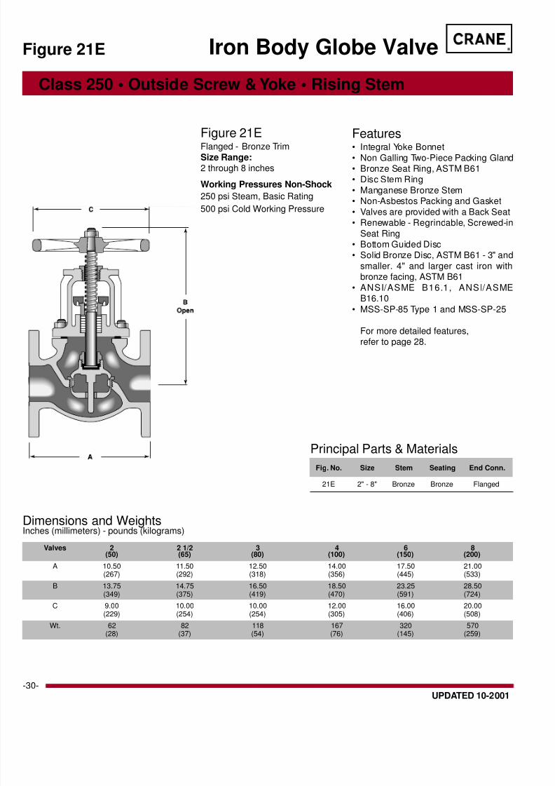
Dimensions and WeightsInches (millimeters) - pounds (kilograms)
Valves 2 2 1/2 3 4 6 8(50) (65) (80) (100) (150) (200)
A 10.50 11.50 12.50 14.00 17.50 21.00(267) (292) (318) (356) (445) (533)
B 13.75 14.75 16.50 18.50 23.25 28.50(349) (375) (419) (470) (591) (724)
C 9.00 10.00 10.00 12.00 16.00 20.00(229) (254) (254) (305) (406) (508)
Wt. 62 82 118 167 320 570(28) (37) (54) (76) (145) (259)
Principal Parts & Materials
Fig. No. Size Stem Seating End Conn.
21E 2" - 8" Bronze Bronze Flanged
Class 250 • Outside Screw & Yoke • Rising Stem
Figure 21E
Features• Integral Yoke Bonnet
• Non Galling Two-Piece Packing Gland• Bronze Seat Ring, ASTM B61• Disc Stem Ring
• Manganese Bronze Stem• Non-Asbestos Packing and Gasket
• Valves are provided with a Back Seat• Renewable - Regrindable, Screwed-in
Seat Ring• Bottom Guided Disc• Solid Bronze Disc, ASTM B61 - 3" and
smaller. 4" and larger cast iron with
bronze facing, ASTM B61• ANSI/ASME B16.1, ANSI/ASME
B16.10
• MSS-SP-85 Type 1 and MSS-SP-25
For more detailed features,refer to page 28.
Figure 21EFlanged - Bronze Trim
Size Range:2 through 8 inches
Working Pressures Non-Shock
250 psi Steam, Basic Rating
500 psi Cold Working Pressure
Iron Body Globe Valve

8/8/2019 craniron
http://slidepdf.com/reader/full/craniron 31/52
®
-UPDATED 10-2001
C
BOp
A
Dimensions and WeightsInches (millimeters) - pounds (kilograms)
Valves 1/2 3/4 1 1 1/4 1 1/2 2(15) (20) (25) (32) (40) (65)
A 2.80 3.31 3.90 4.41 4.92 5.98(71) (84) (99) (112) (125) (152)
B 5.24 5.31 6.73 7.68 8.62 9.80(133) (135) (171) (195) (219) (249)
C 2.56 2.75 3.06 3.62 4.06 4.75(65) (70) (78) (92) (103) (121)
Wt. 1.7 2.5 3.8 5.9 8.0 12.7(0.77) (1.13) (1.72) (2.68) (3.62) (5.76)
Principal Parts & Materials
Fig. No. Size Stem Seating End Conn.
254XR 1/2" - 2" 13 CR. SS Nickel Alloy Threaded
700 SWP/1000 CWP • Rising Stem • Threaded Ends
Figure 254X
Features• Union Bonnet
• Valves are provided with a backseat• Malleable Iron Body and Bonnet
• All sizes are air tested• Disc - Nickel Alloy
• Seat Ring - 13% ChromiumStainless Steel
• Stem - 13% Chromium Stainless
Steel• ANSI/ASME B1.20.1
For more detailed features,
refer to page 28.
Figure 254XRThreaded with 13% ChromiumNickel Alloy
Size Range:1/2 through 2 inches
Malleable Iron Globe Valves
Temperature Working Pressure
°F Non-Shock, psi
-20 - 150° 1000200 960
250 925
300 890350 850
400 810
450 775500 740
550 700

8/8/2019 craniron
http://slidepdf.com/reader/full/craniron 32/52
®
-32- UPDATED 10-2001
BOpen
A
A
C
Dimensions and WeightsInches (millimeters) - pounds (kilograms)
Valves 2 2 1/2 3 4 6(50) (65) (80) (100) (150)
A 4.00 4.25 4.75 5.75 7.00(102) (109) (121) (146) (178)
B 11.00 11.50 12.75 15.00 19.50(279) (292) (324) (381) (495)
C 8.00 8.00 9.00 10.00 12.00(203) (203) (229) (254) (304)
Wt. 32 38 54 88 158(15) (17) (25) (40) (72)
Principal Parts & Materials
Fig. No. Size Stem Seating End Conn.
353 2" - 6" Bronze Bronze Flanged
Class 125 • Outside Screw & Yoke • Rising Stem
Figure 353
Features• Integral Yoke Bonnet with upper and
lower bronze bushings provide for cen-tering of internal parts
• Non Galling Two-Piece Packing Gland• Valves are provided with a Back Seat
• Renewable - Regrindable Screwed-inSeat Ring
• Bottom Guided Disc
• Manganese Bronze Stem• Non-Asbestos Packing & Gasket
• Solid Bronze Disc 6" and smaller• ANSI/ASME B16.1, ANSI/ASME
B16.10• MSS-SP-85 Type 2 and MSS-SP-25
For more detailed features,
refer to page 28.
Figure 353Flanged - Bronze Trim
Size Range:2 through 6 inches
Working Pressures Non-Shock
125 psi Steam, Basic Rating
200 psi Cold Working Pressure
Iron Body Angle Valve

8/8/2019 craniron
http://slidepdf.com/reader/full/craniron 33/52
®
-UPDATED 10-2001
Iron Check Valve Features
Check valves permit flow in one direction
only and close automatically when flow re-
verses. They are entirely automatic in ac-tion, depending upon pressure and veloc-
ity of flow within the line to perform theirfunctions of opening and closing.
The disc and any associated moving parts
may be in a constant state of movement if
the velocity pressure is not sufficient to holdthe disc in a wide open and stable position.
Premature wear and noisy operation or vi-bration can be avoided by selecting the size
of the check valve on the basis of flow con-
ditions rather than selecting the check valveaccording to the size of the pipeline.
Sizing check valves on this basis may of-
ten result in the use of valves that aresmaller than the pipe in which they are
used, necessitating the use of reducers for
installation. The pressure drop will be nogreater than that of a larger valve that is
partially open. Valve life will be greatly ex-tended, and the added bonus, of course, is
the lower cost of the smaller valves.
Each valve in this section is classified by
its pressure rating.
All swing check valves designated as Class125 and 250 comply with MSS SP-71 Stan-dard Practice.
Tilting Disc Check Valves are similar in
application to swing check valves. Essen-
tially, the tilting disc check valve consistsof a cylindrical housing with a pivoted cir-
cular disc. The pivots are located just abovethe center of the disc and offset from the
plane of the body seat. This design de-
creases the travel distance of the disc, andthe closing force due to reversal of flow and
pressure differential is reduced by pivot lo-cation, thereby minimizing slam. The seat
is of a circular bevel type and the disc piv-ots in or out of contact without rubbing or
sliding, while full pressure differential acts
to seal the disc tightly after seating.
Swing Check Valves with straight-through
body design and wide hinge support pro-
vide turbulence-free flow and accurateseating. There is no tendency for seating
surfaces to gall or score because the discmeets the flat seat squarely without rub-
bing. When faster reaction to flow reversal
is necessary, certain valves can beequipped with an outside lever and weight.
This will assist the disc to close more rap-
idly and reduce the possibility of surge andshock.
Crane Iron Check Valves have anidentification tag which indicates the valve
catalog number and other pertinent data. Itprovides easy and accurate field reference.
Features
Threaded Ends in accordance with ANASME B1.20.1.
Flanged Swing Check Valves conforapplicable requirements of ANSI B16.1
sizes 2" through 14". Flanged valves cform to applicable requirements of B
for Class 125 and 250 cast iron sw
check valves.
Bronze Trim Valves are for steam, wanon-corrosive oil and gas and other fl
that do not corrode bronze.
All Iron Valves are for gases, oils and ofluids not corrosive to iron.
Valves May Be Installed in horizonta
vertical pipe lines. In vertical lines, or angle from horizontal, they can be u
for upward flow only.
Non-Asbestos Gaskets and Packin
Identificationplate
Cap bolts
Body
Hinge
Disc washerDisc nut
Disc
CapCap gasket
Cap bolt nutsHinge pin
Hinge pin
Body
Body
Disc
Body seatring
TILTING DISC SWING CHECK

8/8/2019 craniron
http://slidepdf.com/reader/full/craniron 34/52
®
-34- UPDATED 10-2001
A
B
Dimensions and WeightsInches (millimeters) - pounds (kilograms)
Valves 2 2 1/2 3 4(50) (65) (80) (100)
A 6.12 7.25 8.00 9.25(155) (184) (202) (235)
B 4.50 5.38 5.88 6.62(114) (137) (149) (168)
Wt. 18 22 29 54(8) (10) (13) (24)
Principal Parts & Materials
Fig. No. Size Seating End Conn.
372 2" - 4" Bronze Threaded
Class 125 • Bolted Cap • Threaded Ends
Features• Design prohibits galling or scoring
of seating surfaces because thedisc meets the flat seat squarely
on closing with no rubbing action• Replaceable Bronze Seat Rings
• Bronze Hinges• Solid Bronze Disc• Large Bolted-on Cover
• Replaceable Brass Hinge PinBushings
• ANSI/ASME B.1.20.1, MSS-SP-71Type 1 and MSS-SP-25
For more detailed features,refer to page 33.
Figure 372Threaded with Bronze Trim
Size Range:2 through 4 inches
Working Pressures Non-Shock125 psi Steam, Basic Rating200 psi Cold Working Pressure
Iron Body Swing Check ValveFigure 372
8/8/2019 craniron
http://slidepdf.com/reader/full/craniron 35/52
®
-UPDATED 10-2001
Principal Parts & Materials
Fig. No. Size Seating End Conn.
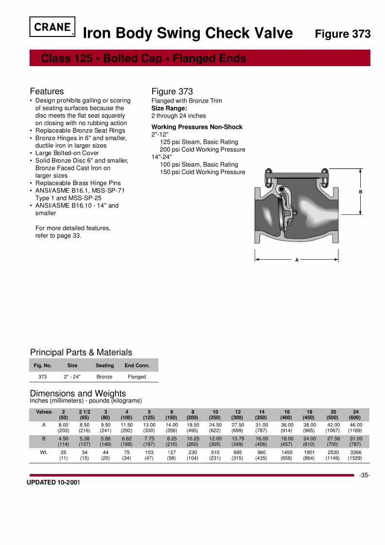
373 2" - 24" Bronze Flanged
Valves 2 2 1/2 3 4 5 6 8 10 12 14 16 18 20 24(50) (65) (80) (100) (125) (150) (200) (250) (300) (350) (400) (450) (500) (600
A 8.00 8.50 9.50 11.50 13.00 14.00 19.50 24.50 27.50 31.00 36.00 38.00 42.00 46.0(203) (216) (241) (292) (330) (356) (495) (622) (699) (787) (914) (965) (1067) (1169
B 4.50 5.38 5.88 6.62 7.75 8.25 10.25 12.00 13.75 16.00 18.00 24.00 27.56 31.0(114) (137) (149) (168) (197) (210) (260) (305) (349) (406) (457) (610) (700) (787
Wt. 25 34 44 75 103 127 230 510 695 960 1450 1901 2530 3366(11) (15) (20) (34) (47) (58) (104) (231) (315) (435) (658) (864) (1149) (1529
Class 125 • Bolted Cap • Flanged Ends
Features• Design prohibits galling or scoring
of seating surfaces because thedisc meets the flat seat squarely
on closing with no rubbing action• Replaceable Bronze Seat Rings
• Bronze Hinges in 6" and smaller,ductile iron in larger sizes
• Large Bolted-on Cover
• Solid Bronze Disc 6" and smaller,Bronze Faced Cast Iron on
larger sizes• Replaceable Brass Hinge Pins
• ANSI/ASME B16.1, MSS-SP-71Type 1 and MSS-SP-25
• ANSI/ASME B16.10 - 14" and
smaller
For more detailed features,refer to page 33.
Dimensions and WeightsInches (millimeters) - pounds (kilograms)
Figure 373Flanged with Bronze Trim
Size Range:2 through 24 inches
Working Pressures Non-Shock2"-12"
125 psi Steam, Basic Rating
200 psi Cold Working Pressure14"-24"
100 psi Steam, Basic Rating150 psi Cold Working Pressure
Iron Body Swing Check Valve Figure 37
A
B
8/8/2019 craniron
http://slidepdf.com/reader/full/craniron 36/52
®
-36- UPDATED 10-2001
Principal Parts & Materials
Fig. No. Size Seating End Conn.
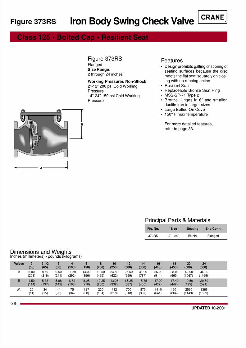
373RS 2" - 24" BUNA Flanged
Valves 2 2 1/2 3 4 6 8 10 12 14 16 18 20 24(50) (65) (80) (100) (150) (200) (250) (300) (350) (400) (450) (500) (600)
A 8.00 8.50 9.50 11.50 14.00 19.50 24.50 27.50 31.00 36.00 38.00 42.00 46.00(203) (216) (241) (292) (356) (495) (622) (699) (787) (914) (965) (1067) (1169)
B 4.50 5.38 5.88 6.62 8.25 10.25 13.06 15.25 15.75 17.00 17.40 19.50 20.50(114) (137) (149) (168) (210) (260) (332) (387) (400) (432) (442) (495) (521)
Wt. 25 34 44 75 127 230 482 700 875 1410 1901 2530 3366(11) (15) (20) (34) (58) (104) (218) (318) (397) (641) (864) (1149) (1529)
Class 125 • Bolted Cap • Resilient Seat
Features• Design prohibits galling or scoring of
seating surfaces because the disc
meets the flat seat squarely on clos-ing with no rubbing action
• Resilient Seat• Replaceable Bronze Seat Ring
• MSS-SP-71 Type 2• Bronze Hinges in 6" and smaller,
ductile iron in larger sizes
• Large Bolted-On Cover• 150° F max temperature
For more detailed features,
refer to page 33.
Dimensions and WeightsInches (millimeters) - pounds (kilograms)
Figure 373RSFlanged
Size Range:2 through 24 inches
Working Pressures Non-Shock2"-12" 200 psi Cold WorkingPressure
14"-24" 150 psi Cold WorkingPressure
Iron Body Swing Check ValveFigure 373RS
A
B
8/8/2019 craniron
http://slidepdf.com/reader/full/craniron 37/52
®
-UPDATED 10-2001
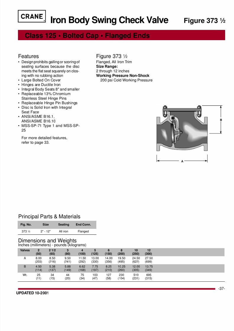
Valves 2 2 1/2 3 4 5 6 8 10 12(50) (65) (80) (100) (125) (150) (200) (250) (300)
A 8.00 8.50 9.50 11.50 13.00 14.00 19.50 24.50 27.50(203) (216) (241) (292) (330) (356) (495) (622) (699)
B 4.50 5.38 5.88 6.62 7.75 8.25 10.25 12.00 13.75(114) (137) (149) (168) (197) (210) (260) (305) (349)
Wt. 25 34 44 75 103 127 230 510 695(11) (15) (20) (34) (47) (58) (104) (231) (315)
Principal Parts & Materials
Fig. No. Size Seating End Conn.
373 1 ⁄ 2 2" - 12" All iron Flanged
Class 125 • Bolted Cap • Flanged Ends
Features• Design prohibits galling or scoring of
seating surfaces because the discmeets the flat seat squarely on clos-ing with no rubbing action
• Large Bolted On Cover• Hinges are Ductile Iron
• Integral Body Seats 8" and smaller• Replaceable 13% Chromium
Stainless Steel Hinge Pins• Replaceable Hinge Pin Bushings• Disc is Solid Iron with Integral
Seat Face
• ANSI/ASME B16.1,ANSI/ASME B16.10
• MSS-SP-71 Type 1 and MSS-SP-
25
For more detailed features,
refer to page 33.
Figure 3731
⁄ 2Flanged, All Iron Trim
Size Range:2 through 12 inches
Working Pressure Non-Shock200 psi Cold Working Pressure
Iron Body Swing Check Valve Figure 373
A
Dimensions and WeightsInches (millimeters) - pounds (kilograms)

8/8/2019 craniron
http://slidepdf.com/reader/full/craniron 38/52
®
-38- UPDATED 10-2001
A
B
Valves 2 2 1/2 3 4 6 8 10 12 14 16 18 20 24(50) (65) (80) (100) (150) (200) (250) (300) (350) (400) (450) (500) (600)
A 8.00 8.50 9.50 11.50 14.00 19.50 24.50 27.50 31.00 36.00 38.00 42.00 46.00(203) (216) (241) (292) (356) (495) (622) (699) (787) (914) (965) (1067) (1169 )
B 4.50 5.38 5.88 6.62 8.25 10.25 12.00 13.75 16.88 19.06 24.00 27.56 31.00(114) (137) (149) (168) (210) (260) (305) (349) (429) (484) (610) (700) (787)
Wt. 30 40 54 85 137 240 545 745 Data on larger sizes(14) (18) (24) (38) (62) (109) (247) (338) available on request
Principal Parts & Materials
Fig. No. Size Seating End Conn.
383 2" - 24" Bronze Flanged
Class 125 • Bolted Cap • Flanged Ends
Features• Design prohibits galling or scoring of
seating surfaces because the discmeets the flat seat squarely on clos-
ing with no rubbing action• Large Bolted On Cover
• Fig. 383 with outside lever andweight is recommended where quick
action is necessary to avoid suddenreversal of flow. Weight can be in-
stalled to balance the disc when ap-plications require that it open underminimum pressure. Positioning and
setting of lever and weight are eas-ily accomplished in the field. Lever
can be rotated through 360° and isadjustable in 15° increments. Valves
may be installed in horizontal or ver-tical pipe lines for upward flow. Ba-sic design of Fig. 383 identical to Fig.
373.• Solid Bronze Disc 6" and smaller;
Bronze Faced in 8" and larger.• Replaceable Stainless Steel Hinge
pins.
• Solid Bronze Hinge 6" and smaller;Ductile Iron for 8" and larger.
For more detailed features,
refer to page 33.
Figure 383Flanged, outside lever and weightwith bronze trim
Size Range:2 through 24 inches
Working Pressure Non-Shock2" - 12"
125 psi Steam, Basic Rating
200 psi Cold Working Pressure14" - 24"
100 psi Steam, Basic Rating150 psi Cold Working Pressure
Iron Body Swing Check ValveFigure 383
Dimensions and WeightsInches (millimeters) - pounds (kilograms)
8/8/2019 craniron
http://slidepdf.com/reader/full/craniron 39/52
®
-UPDATED 10-2001
Dimensions and WeightsInches (millimeters) - pounds (kilograms)
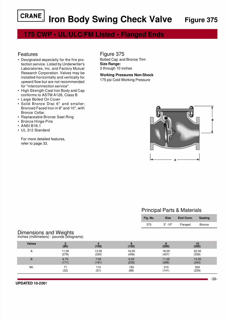
Valves 3 4 6 8 10(80) (100) (150) (200) (250)
A 11.00 13.00 16.00 18.00 22.00(279) (330) (406) (457) (559)
B 6.75 7.50 9.25 11.25 13.50(171) (191) (235) (286) (343)
Wt. 71 113 193 310 504(32) (51) (88) (141) (229)
Principal Parts & Materials
Fig. No. Size End Conn. Seating
375 3" -10" Flanged Bronze
175 CWP • UL/ULC/FM Listed • Flanged Ends
Figure 37
Features• Designated especially for the fire pro-tection service. Listed by Underwriter'sLaboratories, Inc. and Factory Mutual
Research Corporation. Valves may beinstalled horizontally and vertically for
upward flow but are not recommendedfor "interconnection service".
• High Strength Cast Iron Body and Capconforms to ASTM A126, Class B
• Large Bolted On Cover
• Solid Bronze Disc 6" and smaller;Bronzed Faced Iron in 8" and 10", with
Bronze Collar.• Replaceable Bronze Seat Ring
• Bronze Hinge Pins• ANSI B16.1• UL 312 Standard
For more detailed features,
refer to page 33.
Figure 375Bolted Cap and Bronze Trim
Size Range:3 through 10 inches
Working Pressures Non-Shock
175 psi Cold Working Pressure
Iron Body Swing Check Valve
A
8/8/2019 craniron
http://slidepdf.com/reader/full/craniron 40/52
®
-40- UPDATED 10-2001
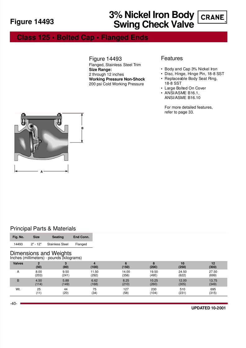
Valves 2 3 4 6 8 10 12(50) (80) (100) (150) (200) (250) (300)
A 8.00 9.50 11.50 14.00 19.50 24.50 27.50(203) (241) (292) (356) (495) (622) (699)
B 4.50 5.88 6.62 8.25 10.25 12.00 13.75(114) (149) (168) (210) (260) (305) (349)
Wt. 25 44 75 127 230 510 695(11) (20) (34) (58) (104) (231) (315)
Principal Parts & Materials
Fig. No. Size Seating End Conn.
14493 2" - 12" Stainless Steel Flanged
Class 125 • Bolted Cap • Flanged Ends
Features• Body and Cap 3% Nickel Iron• Disc, Hinge, Hinge Pin, 18-8 SST
• Replaceable Body Seat Ring,18-8 SST
• Large Bolted On Cover• ANSI/ASME B16.1,
ANSI/ASME B16.10
For more detailed features,
refer to page 33.
Figure 14493Flanged, Stainless Steel Trim
Size Range:2 through 12 inches
Working Pressure Non-Shock200 psi Cold Working Pressure
3% Nickel Iron BodySwing Check ValveFigure 14493
Dimensions and WeightsInches (millimeters) - pounds (kilograms)
A
B

8/8/2019 craniron
http://slidepdf.com/reader/full/craniron 41/52
®
-UPDATED 10-2001
Dimensions and WeightsInches (millimeters) - pounds (kilograms)
Valves 2 2 1/2 3 4 6 8(50) (65) (80) (100) (150) (200)
A 10.50 11.50 12.50 14.00 17.50 21.00(267) (292) (318) (356) (445) (533)
B 5.25 6.00 6.25 7.25 9.00 11.00(133) (152) (159) (184) (229) (279)
Wt. 46 64 90 133 250 410(21) (29) (41) (60) (114) (186)
Principal Parts & Materials
Fig. No. Size Seating End Conn.
39E 2" - 8" Bronze Flanged
Class 250 • Bolted Cap • Flanged Ends
Figure 39
Features• For steam, water, oil, gas and similar
high pressure-temperature conditionswhich do not warrant steel valves.Valves can be installed horizontally, or
vertically for upward flow.• High-Strength Cast Iron Body and Cap
conforms to ASTM A126, Class B.• Solid Bronze Disc in 3" and smaller;
Bronze-faced Iron Disc in 4" and larger.• Screwed-in Bronze Body Seat Ring• Disc moves freely for maximum flow
with minimum pressure drop. A disc
stop, integral with the cap, prohibitsthe disc from sticking open when flowis reversed.
• ANSI/ASME B16.1,ANSI/ASME B16.10
• MSS-SP-71 Type 1 and MSS SP-25
For more detailed features,
refer to page 33.
Figure 39EFlanged - Bronze Trim
Size Range:2 through 8 inches
Working Pressures Non-Shock
250 psi Steam, Basic Rating
500 psi Cold Working Pressure
Iron Body Swing Check Valve
A
B

8/8/2019 craniron
http://slidepdf.com/reader/full/craniron 42/52
®
-42- UPDATED 10-2001
Principal Parts & Materials
Fig. No. Size Seating End Conn.
346 1 ⁄ 2 1 ⁄ 2" - 2" Iron Threaded
Valves 1/2 3/4 1 1 1/4 1 1/2 2(15) (20) (25) (32) (40) (50)
A 2.76 3.28 4.05 4.75 5.40 6.62(70) (83) (103) (120) (137) (168)
B 1.68 2.00 2.50 2.85 3.29 4.28(43) (51) (62) (73) (84) (109)
Wt. 1.0 1.5 2.5 2.9 5.8 10.0(0.43) (0.65) (1.11) (1.30) (2.61) (4.51)
700 SWP/1000 CWP • Y-Pattern • Threaded Ends
Features• Malleable Iron Body and Cap
• Hinge Pin 13% ChromiumStainless Steel
• ASME B1.20.1
For more detailed features,
refer to page 33.
Figure 3461
⁄ 2Threaded - Malleable Iron
Size Range:1/2 through 2 inches
Malleable IronSwing Check ValveFigure 346 1 ⁄ 2
Dimensions and WeightsInches (millimeters) - pounds (kilograms)
B
A
Temperature Working Pressure
°F Non-Shock, psi
-20 - 150° 1000200 960
250 925300 890
350 850
400 810450 775
500 740550 700

8/8/2019 craniron
http://slidepdf.com/reader/full/craniron 43/52
®
-UPDATED 10-2001
Principal Parts & Materials
Fig. No. Size Seating End Conn.
23 2" - 24" Bronze Flanged
Valves 2 2 1/2 3 4 6 8 10 12 14 16 18 20 24(50) (65) (80) (100) (150) (200) (250) (300) (350) (400) (450) (500) (600
A 9.5 9.5 9.5 11.5 14.0 19.5 24.5 27.5 31.0 30.0 33.0 32.5 38.0(241) (241) (241) (292) (356) (495) (622) (698) (787) (762) (838) (826) (965
B 7.50 7.50 7.50 9.75 11.88 14.88 17.75 19.50 22.38 25.88 29.00 31.00 36.5(190) (190) (190) (248) (302) (378) (451) (495) (568) (657) (737) (787) (927
C 11.50 11.50 11.50 14.50 16.50 20.25 25.25 26.50 29.38 33.62 37.25 39.75 47.0(292) (292) (292) (368) (419) (514) (641) (673) (746) (854) (946) (1010) (1193
Wt. 40 50 60 105 165 225 415 635 990 1050 1500 1720 3200(18) (23) (27) (48) (75) (102) (188) (288) (449) (476) (680) (780) (1451
Class 125 • Flanged Ends
Figure 2
Features• Disc Solid Bronze 10" and smaller.
Larger sizes ductile iron with bronzeseating face
• 24" and larger have disc positionindicator
• Discs are designed with "Aerofoil"configuration
• ANSI B16.1
For more detailed features,
refer to page 33.
Figure 23Flanged - Bronze Trim
Size Range:2 through 24 inches
Working Pressures Non-Shock
2" - 12"
125 psi Steam, Basic Rating
200 psi Cold Working Pressure
14" - 24"
100 psi Steam, Basic Rating
150 psi Cold Working Pressure
Tilting Disc Check Valve
Dimensions and WeightsInches (millimeters) - pounds (kilograms)
A
B
C

8/8/2019 craniron
http://slidepdf.com/reader/full/craniron 44/52
®
-44- UPDATED 10-2001
Dimensions and WeightsInches (millimeters) - pounds (kilograms)
Valves 2 2 1/2 3 4 6 8 10 12 14 16 18 20 24(50) (65) (80) (100) (150) (200) (250) (300) (350) (400) (450) (500) (600)
A 9.5 9.5 9.5 11.5 14.0 19.5 24.5 27.5 31.0 30.0 33.0 32.5 38.0(241) (241) (241) (292) (356) (495) (622) (698) (787) (762) (838) (826) (965)
B 7.50 7.50 7.50 9.75 11.88 14.88 17.75 19.50 22.38 25.88 29.00 31.00 36.50(190) (190) (190) (248) (302) (378) (451) (495) (568) (657) (737) (787) (927)
C 11.50 11.50 11.50 14.50 16.50 20.25 25.25 26.50 29.38 33.62 37.25 39.75 47.00(292) (292) (292) (368) (419) (514) (641) (673) (746) (854) (946) (1010) (1193)
Wt. 40 50 60 105 165 225 415 635 990 1050 1500 1720 3200(18) (23) (27) (48) (75) (102) (188) (288) (449) (476) (680) (780) (1451)
Principal Parts & Materials
Fig. No. Size Seating End Conn.
24 2" - 24" Iron Flanged
Class 125 • Flanged Ends
Features• Disc 10" and smaller cast iron,
larger sizes ductile iron with integralseat face
• 24" and larger have disc positionindicator
• Discs are designed with an"Aerofoil" configuration
• ANSI B16.1
For more detailed features,
refer to page 33.
Figure 24Flanged - All Iron
Size Range:2 through 24 inches
Working Pressure Non-Shock2" - 12"
200 psi Cold Working Pressure14" - 24"
150 psi Cold Working Pressure
Tilting Disc Check ValveFigure 24
A
B
C

8/8/2019 craniron
http://slidepdf.com/reader/full/craniron 45/52
®
-UPDATED 10-2001
A
B
C
Dimensions and WeightsInches (millimeters) - pounds (kilograms)
Valves 2 2 1/2 3 4 6 8 10 12 14 16 18 20 24(50) (65) (60) (100) (150) (200) (250) (300) (350) (400) (450) (500) (600
A 9.50 11.00 12.50 14.00 17.50 21.00 24.50 28.00 30.00 33.00 36.00 39.00 45.0(241) (279) (318) (356) (445) (533) (622) (711) (762) (838) (914) (991) (1143
B 7.50 7.75 7.75 9.75 15.00 15.25 18.12 21.00 24.75 27.50 30.00 31.62 37.5(191) (197) (197) (248) (381) (387) (460) (533) (629) (699) (762) (803) (953
C 11.50 11.50 11.50 11.50 20.00 21.38 24.25 27.50 31.62 34.88 37.00 41.50 50.5(292) (292) (292) (292) (508) (543) (616) (699) (803) (886) (940) (1054) (1283
Wt. 60 60 70 115 300 410 550 785 1100 1250 1800 2400 3800(27) (27) (32) (52) (136) (186) (249) (356) (499) (567) (71) (1088) (1723
Principal Parts & Materials
Fig. No. Size Seating End Conn.
223 2" - 24" Bronze Flanged
Class 250 • Flanged Ends
Figure 22
Features• Disc solid bronze 8" and smaller.
Larger sizes ductile iron withbronze seating face
• 24" and larger have disc positionindicator
• Discs are designed with an"Aerofoil" configuration
• ANSI B16.1
For more detailed features,
refer to page 33.
Figure 223Flanged - Bronze Trim
Size Range:2 through 24 inches
Working Pressures Non-Shock
2" - 12"
250 psi Steam, Basic Rating
500 psi Cold Working Pressure
14" - 24"
200 psi Steam, Basic Rating
300 psi Cold Working Pressure
Tilting Disc Check Valve

8/8/2019 craniron
http://slidepdf.com/reader/full/craniron 46/52
®
-46- UPDATED 10-2001
Dimensions and WeightsInches (millimeters) - pounds (kilograms)
Valves 2 2 1/2 3 4 6 8 10 12 14 16 18 20 24(50) (65) (80) (100) (150) (200) (250) (300) (350) (400) (450) (500) (600)
A 9.50 11.00 12.50 14.00 17.50 21.00 24.50 28.00 30.00 33.00 36.00 39.00 45.00(241) (279) (318) (356) (444) (533) (622) (711) (762) (838) (914) (991) (1143)
B 7.50 7.75 7.75 9.75 15.00 15.25 18.12 21.00 24.75 27.50 30.00 31.62 37.50(191) (197) (197) (248) (381) (387) (460) (533) (629) (698) (762) (803) (953)
C 11.50 11.50 11.50 11.50 20.00 21.38 24.25 27.50 31.62 34.88 37.00 41.50 50.50(292) (292) (292) (292) (508) (543) (616) (698) (803) (886) (940) (1054) (1282)
Wt. 60 60 70 115 300 410 550 785 1100 1250 1800 2400 3800(27) (27) (32) (52) (136) (186) (249) (356) (499) (567) (816) (1088) (1723)
Principal Parts & Materials
Fig. No. Size Seating End Conn.
224 2" - 24" Iron Flanged
Class 250 • Flanged Ends
Features• Disc 8" and smaller cast iron. Larger
sizes ductile iron with integral seatfaces
• 24" and larger have disc positionindicator
• Discs are designed with an"Aerofoil" configuration
• ANSI B16.1
For more detailed features,
refer to page 33.
Figure 224Flanged - All Iron
Size Range:2 through 24 inches
Working Pressure Non-Shock2" - 12"
500 psi Cold Working Pressure
14" - 24"300 psi Cold Working Pressure
Tilting Disc Check ValveFigure 224
A
B
C

8/8/2019 craniron
http://slidepdf.com/reader/full/craniron 47/52
®
-UPDATED 10-2001
Valves 2 1/2 3 4 5 6 8 10(65) (80) (100) (125) (150) (200) (250)
A 13.00 14.75 17.00 19.00 21.50 26.00 30.00(330) (375) (432) (483) (546) (660) (762)
C* 5.00 7.25 7.75 10.50 11.75 16.25 17.75(127) (184) (197) (267) (298) (413) (451)
E* 15.75 19.75 21.75 25.75 29.25 36.75 41.75(400) (502) (552) (654) (743) (933) (1060)
G 9.00 10.00 10.00 14.00 16.00 20.00 20.00(229) (254) (254) (356) (406) (508) (508)
Wt. 103 140 226 307 420 737 1250(47) (64) (103) (139) (191) (335) (568)
Figure 28
Features• For installation between boilers suppling
the same steam header, and positionedwith pressure under the disc. Straight-way is for horizontal or vertical line with
upward flow. Angle valves are for "hori-zontal-downward" or "upward-horizontal"flow.
• These valves will perform the four follow-ing important functions:
1. Act as an automatic-non return valveapplied as a containment device to pre-vent gross backflow of steam from mainheader to boiler in case the boiler fails.
2. Assist in cutting out boiler, when ceasingto fire. In this case, valve disc automati-cally closes to restrict backflow of steamto the boiler.
3. Assist in returning boiler after a shutdown.4. Restricts backflow of steam from header
into boiler which has been shut down andaccidently opened. The check valve fea-ture should not be relied upon for primaryshut-off.
• Cylindrical shaped disc is the only pres-sure-actuated part, light in weight with
Iron Body Stop Check Valve
ample guiding surface. It is specially de-
signed to produce a maximum lift at mini-mum velocities. There are no wing guidesto cause "spinning" with resultant rapidwear.
• Long throttling lip on disc retards flowwhen seating position is approached. Discchattering is prevented and wiredrawingof seating surfaces is reduced.
• Flat Seats, accurately machined, facilitatetrue seating.
• Removable cast iron liner guides the discthroughout its full travel. Being entirelyindependent of the body, it is not subjectto distortion by expansion strains.
• Piston Ring 6" and larger adds todashpot's ability to avoid rapid disc move-ments. Where pulsations are extremelysevere, two rings can be installed.
• Dashpot is self-contained in the liner. Itprovides an effective cushion for the discto prevent pipe line vibrations or hammer-ing on the seat at low velocities or on pul-sating loads.
• Flanges conform to ANSI B16.1. Flangeshave 1/16" raised face with concentricgrooves.
• The body has integral bosses for drain
connections. The bosses are tapped andplugged.
• Determining the proper valve size neededis important. The size of a stop checkvalve should be based on the boiler ca-pacity and steam flow through the valve,rather than on the size of the boiler outletor existing piping.
Figure 28E
Flanged, Y-Pattern with BoltedBonnet Straightway
Size Range:2-1/2 through 10 inches
Working Pressures Non-Shock
250 psi Steam, Basic Rating
500 psi Cold Working Pressure
Class 250 • Y-Pattern • Flanged Ends • Straightway
COpen
EOpen
G
A
Dimensions and WeightsInches (millimeters) - pounds (kilograms)

8/8/2019 craniron
http://slidepdf.com/reader/full/craniron 48/52
®
-48- UPDATED 10-2001
Dimensions and Weights
Inches (millimeters) - pounds (kilograms)Valves 2 1/2 3 4 5 6 8 10
(65) (80) (100) (125) (150) (200) (250)
B 5.75 6.25 7.00 7.88 8.75 10.50 12.25(146) (159) (178) (200) (222) (267) (311)
D 14.50 16.50 18.50 22.00 25.50 33.25 37.75(368) (419) (470) (559) (648) (845) (959)
F 13.25 14.75 16.25 19.50 22.50 28.75 32.50(337) (375) (413) (495) (572) (730) (826)
G 9.00 10.00 10.00 14.00 16.00 20.00 20.00(229) (254) (254) (356) (406) (508) (508)
Wt. 86 123 186 250 340 640 1025(39) (56) (84) (113) (154) (291) (465)
Class 250 • Y-Pattern • Flanged Ends • Angle
Figure 30E
Features• For installation between boilers suppling
the same steam header, and positionedwith pressure under the disc. Straight-
way is for horizontal or vertical line withupward flow. Angle valves are for "hori-zontal-downward" or "upward-horizontal"flow.
• These valves will perform the four follow-ing important functions:
1. Act as an automatic-non return valveapplied as a containment device to pre-vent gross backflow of steam from mainheader to boiler in case the boiler fails.
2. Assist in cutting out boiler, when ceasingto fire. In this case, valve disc automati-cally closes to restrict backflow of steamto the boiler.
3. Assist in returning boiler after a shutdown.4. Restricts backflow of steam from header
into boiler which has been shut down andaccidently opened. The check valve fea-ture should not be relied upon for primaryshut-off.
• Cylindrical shaped disc is the only pres-sure-actuated part, light in weight with
Iron Body Stop Check Valve
ample guiding surface. It is specially de-signed to produce a maximum lift at mini-mum velocities. There are no wing guidesto cause "spinning" with resultant rapidwear.
• Long throttling lip on disc retards flowwhen seating position is approached. Discchattering is prevented and wiredrawingof seating surfaces is reduced.
• Flat Seats, accurately machined, facilitatetrue seating.
• Removable cast iron liner guides the discthroughout its full travel. Being entirelyindependent of the body, it is not subjectto distortion by expansion strains.
• Piston Ring 6" and larger adds todashpot's ability to avoid rapid disc move-ments. Where pulsations are extremelysevere, two rings can be installed.
• Dashpot is self-contained in the liner. Itprovides an effective cushion for the discto prevent pipe line vibrations or hammer-ing on the seat at low velocities or on pul-sating loads.
• Flanges conform to ANSI B16.1. Flangeshave 1/16" raised face with concentricgrooves.
• The body has integral bosses for drain
connections. The bosses are tapped andplugged.
• Determining the proper valve size neededis important. The size of a stop checkvalve should be based on the boiler ca-pacity and steam flow through the valve,rather than on the size of the boiler outletor existing piping.
Figure 30E
Flanged, Y-Pattern withBolted Bonnet Angle
Size Range:2-1/2 through 10 inches
Working Pressures Non-Shock250 psi Steam, Basic Rating500 psi Cold Working Pressure
G
B
B DOpen
FOpen

8/8/2019 craniron
http://slidepdf.com/reader/full/craniron 49/52
®
-UPDATED 10-2001
2. From that point, draw another line through the valve size,example the 8-inch size, and establish a point on Index 2. Nmove horizontally to the diagonal pressure drop line on
right side. Where these lines intersect, the pressure drop ispsi for the 8-inch, Class 250 globe valve and 8.5 psi for the
inch Class 250 angle valve.
Chart solutions resulting in a point on Index 2 that falls below
Line A-A for Class 250 valves indicate the disc will not be flifted under the flow conditions used. Operation under s
conditions is not recommended but, at times, must be tolera
for short periods during the low loads.
3. Enter the chart where Line A-A intersects Index 2 for Class
valves. Move diagonally upward through the size being invtigated (8-inch) and establish a second point on Index 1. Frthis point, extend a line to the specific volume established
Step 1 and at its intersection with the flow rate line, read 48,0
Lb/H as the minimum flow rate at which the disc will be in fully lifted position. The pressure drop at this flow rate is 1.9
for globe and 2.1 psi for angle valves.
4. Repeat Steps 2 and 3 for other possible valve sizes, tabul
results, and make size selection on basis of pressure drop aduration of partial disc lift considerations.
Dotted lines on Demand Curve indicate minimum flow rateswide open 8" and 10" valves.
5. The best choice for this example would be the 10" s
because pressure drop is much lower and duration of parti
lifted disc is only slightly greater than for the 8" size.
6. Pressure drop for any intermediate flow condition can
determined as outlined in Steps 1 and 2.
Selecting the Proper Size –
Determining Pressure Drop
Since stop-check valves have a floating disc member, it is impor-
tant the valve be sized to provide full disc lift under flow conditionsprevailing during the major portion of the service life. If the valve
is too large, the disc will float in a partially open position and may
cause fluttering of the disc and rapid wear. Conversely, if the valveis too small, pressure drop will be excessive.
The chart on the following page is a graphic presentation of flowdata determined by test. Its use offers a simple method of deter-
mining the best size stop-check valve, as well as the pressure dropunder varying conditions of flow, without any computation.
How to Use the ChartShown on the Following Page
Given: Steam Pressure-Temperature...250 psig 450°FFlow Rate...Typical Daily Demand Curve
Bolted Bonnet Stop Check Valve
Find: Valve Catalog No. and the best size for above installation.
Solution:1. Enter the Temperature chart at 450°F. Move vertically upward
to the curved line for 250 psi, then horizontally to the right to
establish a point on the specific volume scale. From this point,
draw a line through the flow rate being investigated (100,000Lb/H) and establish a point on Index 1.
Valve Press drop @ Max.Min. Flow Rate foSize Flow rate (100,000 #/Hr.), psi Wide open val
(Inches) Globe Angle #/Hr.
6 20.5 22.5 26,5008 7.5 8.5 48,000
10 3.3 3.6 68,000
12Midnight
12Midnight
6AM
12Noon
6PM
0
TIME OF DAY
Typical Daily Load-Demand Curve
R A T E O F F L O W I
N P O U N D S P E R H O U R
10,000
20,000
30,000
40,000
50,000
60,000
70,000
80,000
90,000
100,000
10-Inch Valve
8-Inch Valve
Technical Data • Y-Pattern Stop Check Valve

8/8/2019 craniron
http://slidepdf.com/reader/full/craniron 50/52
®
-50- UPDATED 10-2001
CraneBoltedBonnetStop-CheckVa
lves
Selectin
gtheProperSize
–
DeterminingPressureDrop
Technical Data • Y-Pattern Stop Check Valve
Iron Valves

8/8/2019 craniron
http://slidepdf.com/reader/full/craniron 51/52
®
-UPDATED 10-2001
BOILER
BOILER
BOILER
BOILER
DRAIN
DRAIN
DRAIN
DRAIN
DRAIN
DRAIN
HEADER
HEADER
HEADER
HEADER
Straight-WayY-Pattern
Installed in ahorizontal line
Straight-WayY-Pattern
Installed in a vertical line
for upward flow
Angle Y-PatternInstalled for upward-
to-horizontal flow
Angle Y-PatternInstalled for
horizontal-to-downward flow
Y-Pattern Stop-Check and Isolation Gate Valves
Installation Recommendations
As shown in these diagrams, Crane Y-Pattern s
check valves used in a boiler installation can be positio
for horizontal or upward flow. The proper methoddraining both Y-pattern stop-check valves and isola
gate valves is shown for typical mounting positiTapped and plugged drain holes are furnished. For
efficiency, be sure the proper size valve is used.

8/8/2019 craniron
http://slidepdf.com/reader/full/craniron 52/52


