Embed Size (px)
Citation preview
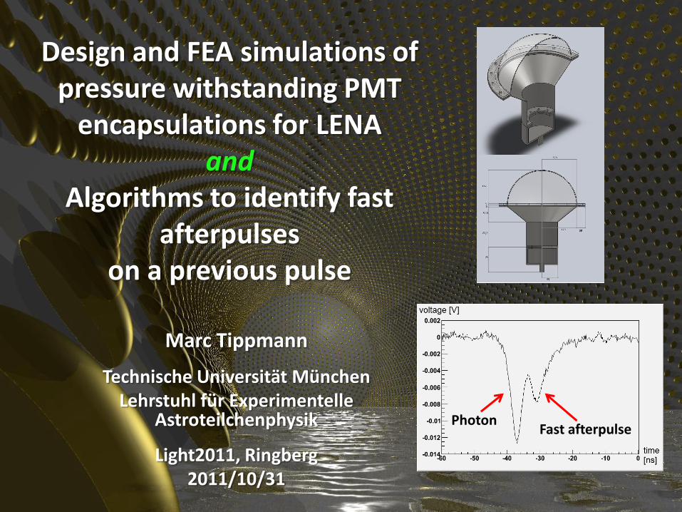
Design and FEA simulations of pressure withstanding PMT
encapsulations for LENA and
Algorithms to identify fast afterpulses
on a previous pulse
Marc Tippmann
Technische Universität München Lehrstuhl für Experimentelle
Astroteilchenphysik
Light2011, Ringberg 2011/10/31
Photon Fast afterpulse
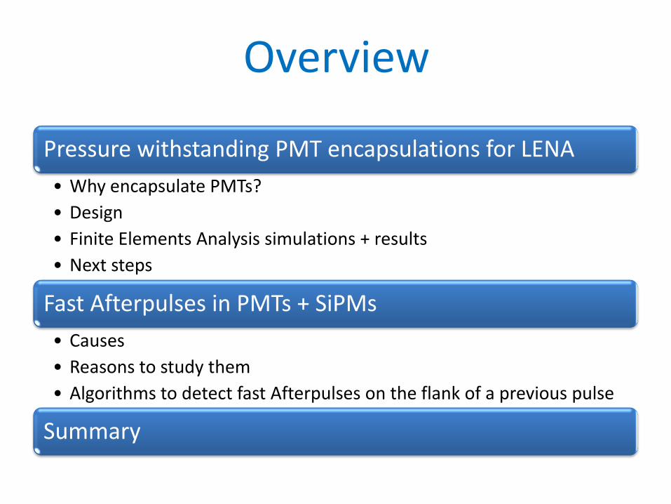
Overview
Pressure withstanding PMT encapsulations for LENA
• Why encapsulate PMTs?
• Design
• Finite Elements Analysis simulations + results
• Next steps
Fast Afterpulses in PMTs + SiPMs
• Causes
• Reasons to study them
• Algorithms to detect fast Afterpulses on the flank of a previous pulse
Summary
Pressure withstanding PMT encapsulations for LENA
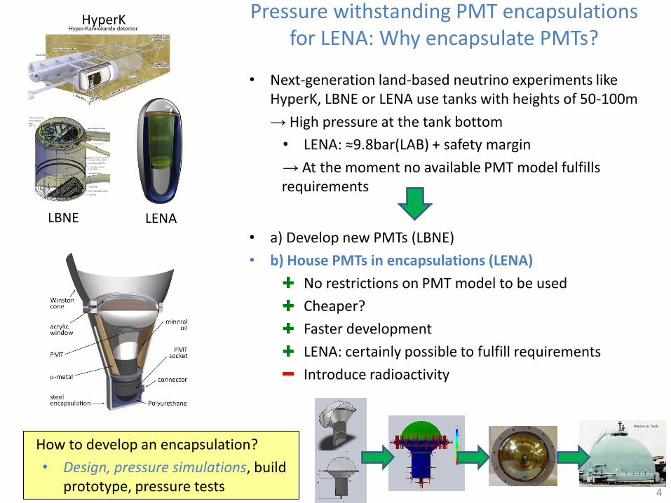
Pressure withstanding PMT encapsulations for LENA: Why encapsulate PMTs?
4
How to develop an encapsulation?
• Design, pressure simulations, build prototype, pressure tests
LENA LBNE
HyperK
• Next-generation land-based neutrino experiments like HyperK, LBNE or LENA use tanks with heights of 50-100m
→ High pressure at the tank bottom
• LENA: ≈9.8bar(LAB) + safety margin
→ At the moment no available PMT model fulfills requirements
• a) Develop new PMTs (LBNE)
• b) House PMTs in encapsulations (LENA)
No restrictions on PMT model to be used
Cheaper?
Faster development
LENA: certainly possible to fulfill requirements
Introduce radioactivity
German Beischler
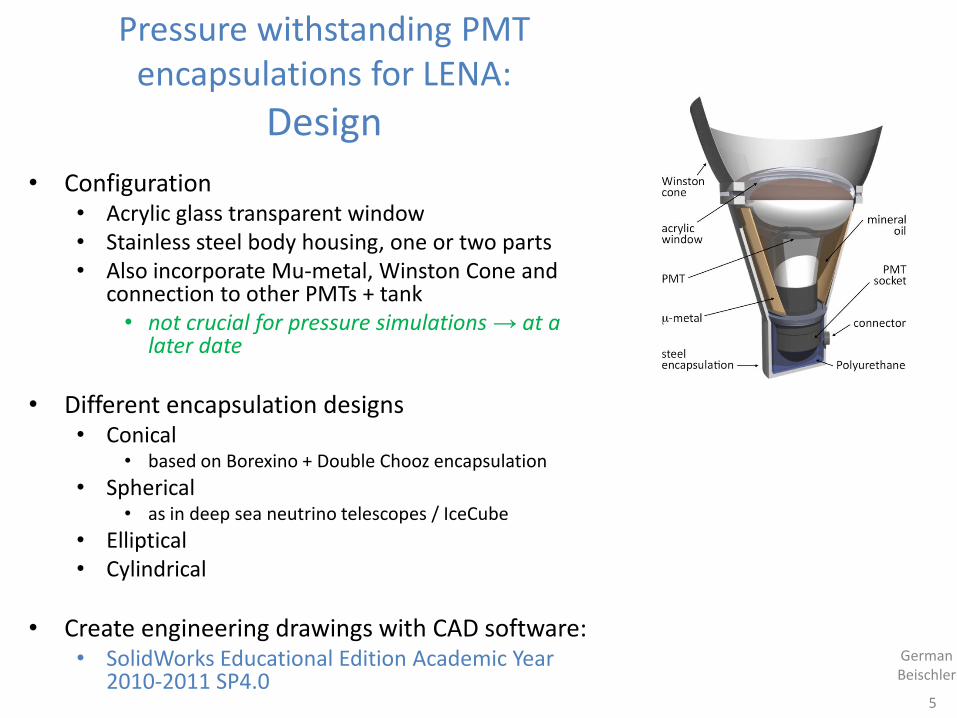
• Configuration • Acrylic glass transparent window • Stainless steel body housing, one or two parts • Also incorporate Mu-metal, Winston Cone and
connection to other PMTs + tank • not crucial for pressure simulations → at a
later date
• Different encapsulation designs • Conical
• based on Borexino + Double Chooz encapsulation
• Spherical • as in deep sea neutrino telescopes / IceCube
• Elliptical • Cylindrical
• Create engineering drawings with CAD software: • SolidWorks Educational Edition Academic Year
2010-2011 SP4.0
Pressure withstanding PMT encapsulations for LENA:
Design
5
German Beischler
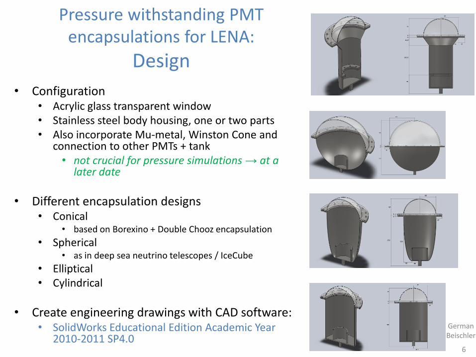
• Configuration • Acrylic glass transparent window • Stainless steel body housing, one or two parts • Also incorporate Mu-metal, Winston Cone and
connection to other PMTs + tank • not crucial for pressure simulations → at a
later date
• Different encapsulation designs • Conical
• based on Borexino + Double Chooz encapsulation
• Spherical • as in deep sea neutrino telescopes / IceCube
• Elliptical • Cylindrical
• Create engineering drawings with CAD software: • SolidWorks Educational Edition Academic Year
2010-2011 SP4.0
Pressure withstanding PMT encapsulations for LENA:
Design
6
Pressure withstanding PMT encapsulations for LENA: Pressure simulations
• Simulate behaviour under pressure with a Finite Elements Analysis (FEA) simulation software – Engineering drawings and FEA pressure simulations were done with same software
• Software: SolidWorks Educational Edition Academic Year 2010-2011 SP4.0, Simulation Premium package
• Settings: Linear static study, 12bar pressure, node distance 3mm ± 0.15mm
• Materials: High impact resistant acrylic glass, 1,4404 stainless steel X2CrNiMo17-12-2
• Computer: Intel i7-2600, 8GB DDR3-RAM, AMD Radeon HD 6450 1GB GDDR3, Win7 Prof. 64bit
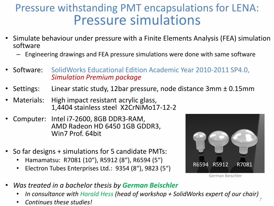
• So far designs + simulations for 5 candidate PMTs: • Hamamatsu: R7081 (10“), R5912 (8“), R6594 (5“) • Electron Tubes Enterprises Ltd.: 9354 (8“), 9823 (5“)
• Was treated in a bachelor thesis by German Beischler • In consultance with Harald Hess (head of workshop + SolidWorks expert of our chair) • Continues these studies!
7
R6594 R5912 R7081
German Beischler
Pressure withstanding PMT encapsulations for LENA:
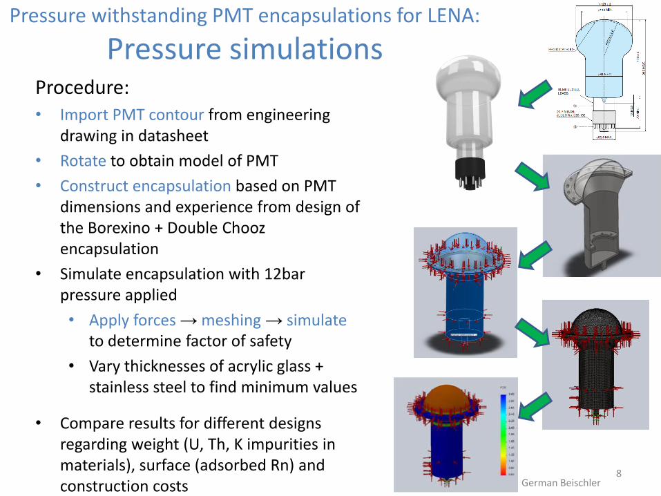
Pressure simulations Procedure: • Import PMT contour from engineering
drawing in datasheet
• Rotate to obtain model of PMT
• Construct encapsulation based on PMT dimensions and experience from design of the Borexino + Double Chooz encapsulation
• Simulate encapsulation with 12bar pressure applied
• Apply forces → meshing → simulate to determine factor of safety
• Vary thicknesses of acrylic glass + stainless steel to find minimum values
• Compare results for different designs regarding weight (U, Th, K impurities in materials), surface (adsorbed Rn) and construction costs
8 German Beischler
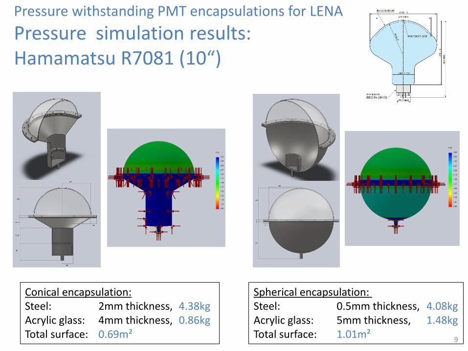
Spherical encapsulation: Steel: 0.5mm thickness, 4.08kg Acrylic glass: 5mm thickness, 1.48kg Total surface: 1.01m²
Pressure withstanding PMT encapsulations for LENA
Pressure simulation results: Hamamatsu R7081 (10“)
9
Conical encapsulation: Steel: 2mm thickness, 4.38kg Acrylic glass: 4mm thickness, 0.86kg Total surface: 0.69m²
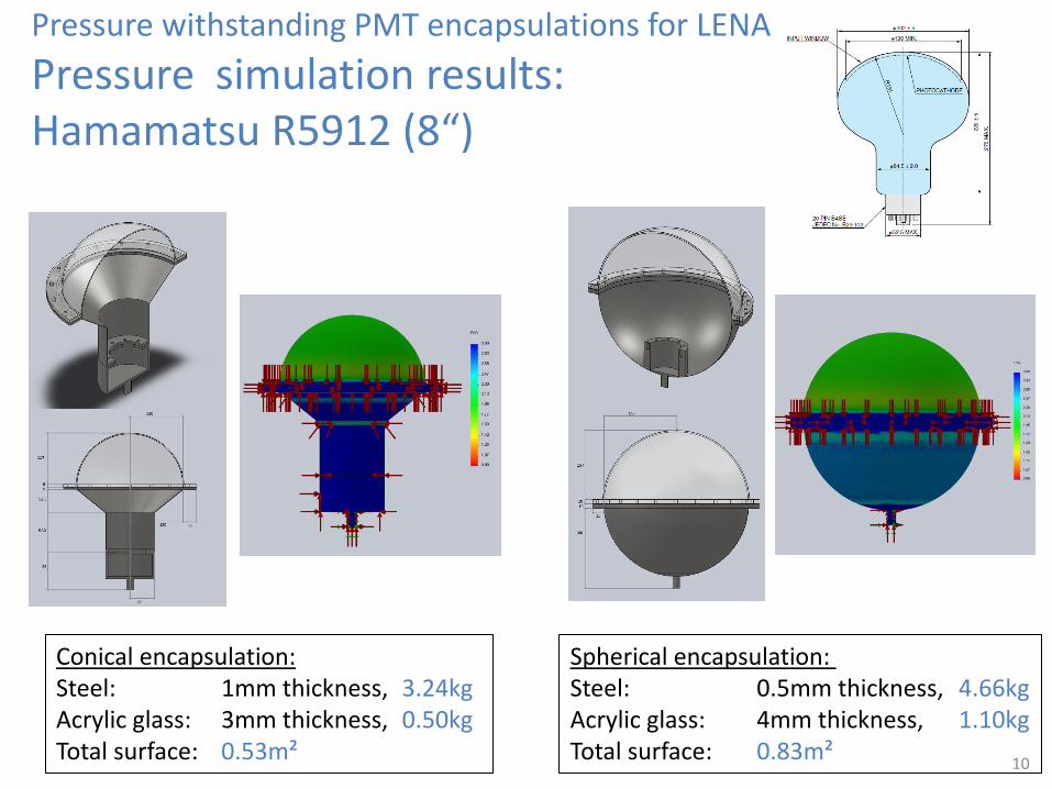
Spherical encapsulation: Steel: 0.5mm thickness, 4.66kg Acrylic glass: 4mm thickness, 1.10kg Total surface: 0.83m²
Pressure withstanding PMT encapsulations for LENA
Pressure simulation results: Hamamatsu R5912 (8“)
10
Conical encapsulation: Steel: 1mm thickness, 3.24kg Acrylic glass: 3mm thickness, 0.50kg Total surface: 0.53m²
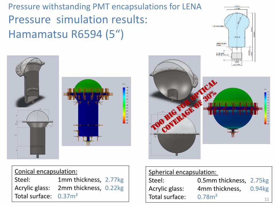
Spherical encapsulation: Steel: 0.5mm thickness, 2.75kg Acrylic glass: 4mm thickness, 0.94kg Total surface: 0.78m²
Pressure withstanding PMT encapsulations for LENA
Pressure simulation results: Hamamatsu R6594 (5“)
Conical encapsulation: Steel: 1mm thickness, 2.77kg Acrylic glass: 2mm thickness, 0.22kg Total surface: 0.37m²
11
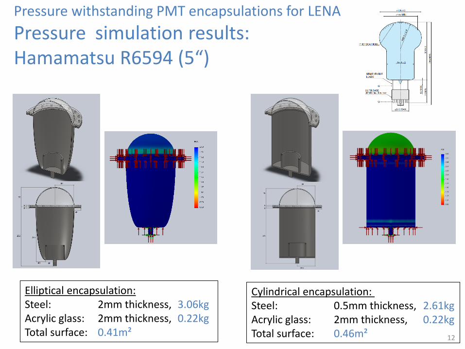
Cylindrical encapsulation: Steel: 0.5mm thickness, 2.61kg Acrylic glass: 2mm thickness, 0.22kg Total surface: 0.46m²
Pressure withstanding PMT encapsulations for LENA
Pressure simulation results: Hamamatsu R6594 (5“)
Elliptical encapsulation: Steel: 2mm thickness, 3.06kg Acrylic glass: 2mm thickness, 0.22kg Total surface: 0.41m²
12
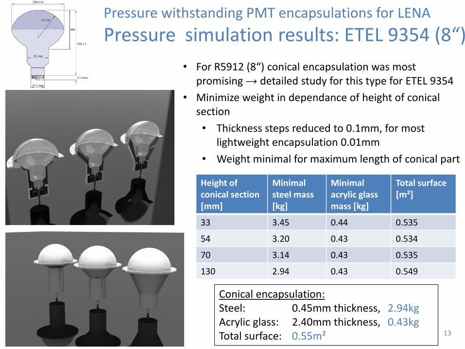
• For R5912 (8“) conical encapsulation was most promising → detailed study for this type for ETEL 9354
• Minimize weight in dependance of height of conical section
• Thickness steps reduced to 0.1mm, for most lightweight encapsulation 0.01mm
• Weight minimal for maximum length of conical part
13
Pressure withstanding PMT encapsulations for LENA
Pressure simulation results: ETEL 9354 (8“)
Height of conical section [mm]
Minimal steel mass [kg]
Minimal acrylic glass mass [kg]
Total surface [m²]
33 3.45 0.44 0.535
54 3.20 0.43 0.534
70 3.14 0.43 0.535
130 2.94 0.43 0.549
Conical encapsulation: Steel: 0.45mm thickness, 2.94kg Acrylic glass: 2.40mm thickness, 0.43kg Total surface: 0.55m²
14
Pressure withstanding PMT encapsulations for LENA
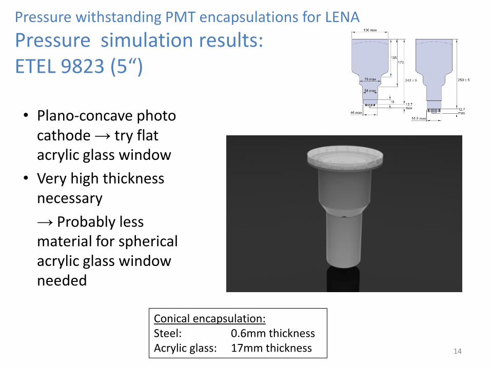
Pressure simulation results: ETEL 9823 (5“)
Conical encapsulation: Steel: 0.6mm thickness Acrylic glass: 17mm thickness
• Plano-concave photo cathode → try flat acrylic glass window
• Very high thickness necessary
→ Probably less material for spherical acrylic glass window needed
Pressure withstanding PMT encapsulations for LENA
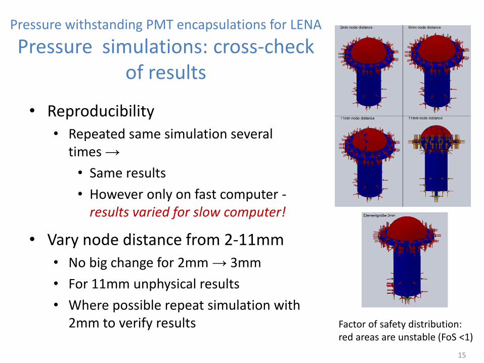
Pressure simulations: cross-check of results
• Reproducibility
• Repeated same simulation several times →
• Same results
• However only on fast computer - results varied for slow computer!
• Vary node distance from 2-11mm
• No big change for 2mm → 3mm
• For 11mm unphysical results
• Where possible repeat simulation with 2mm to verify results
15
Factor of safety distribution: red areas are unstable (FoS <1)
Pressure withstanding PMT encapsulations for LENA
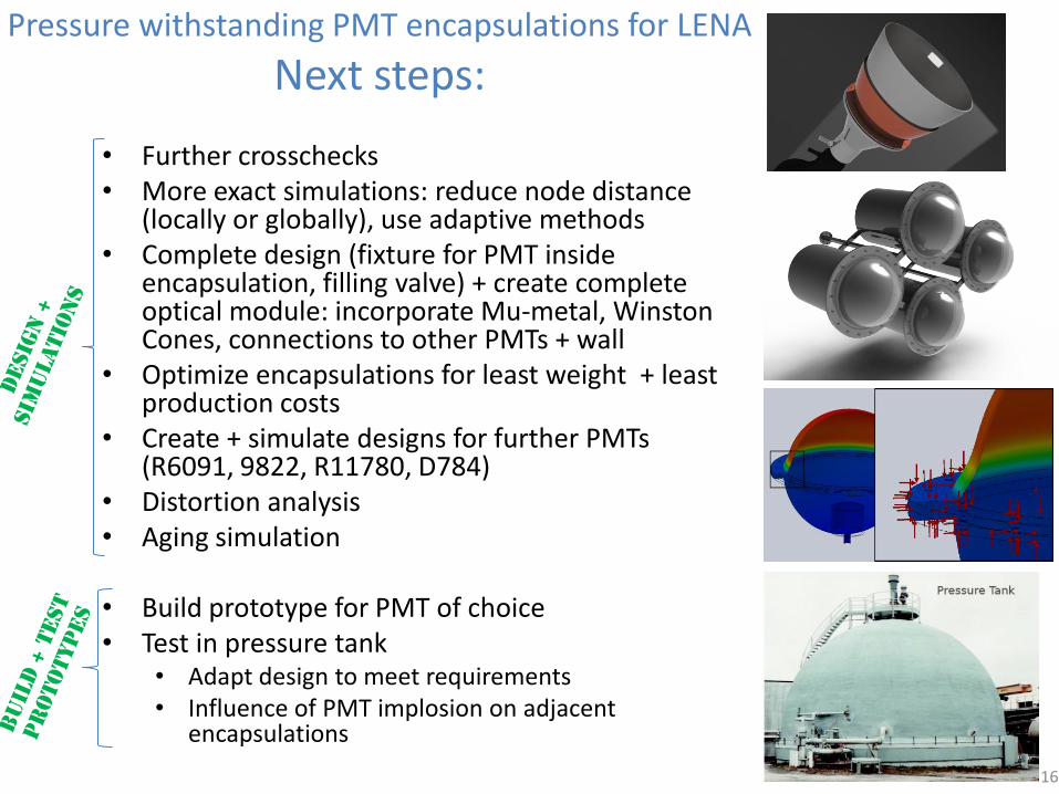
Next steps:
• Further crosschecks • More exact simulations: reduce node distance
(locally or globally), use adaptive methods • Complete design (fixture for PMT inside
encapsulation, filling valve) + create complete optical module: incorporate Mu-metal, Winston Cones, connections to other PMTs + wall
• Optimize encapsulations for least weight + least production costs
• Create + simulate designs for further PMTs (R6091, 9822, R11780, D784)
• Distortion analysis • Aging simulation
• Build prototype for PMT of choice • Test in pressure tank
• Adapt design to meet requirements • Influence of PMT implosion on adjacent
encapsulations
16
Fast Afterpulses in PMTs and SiPMs
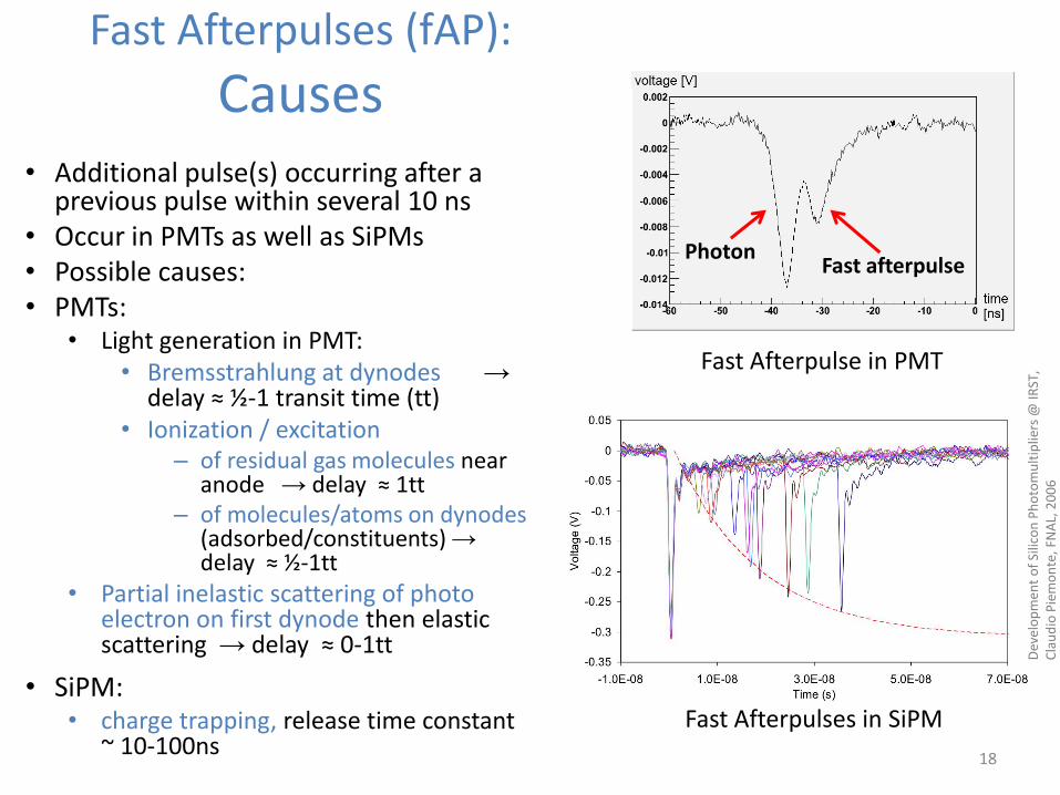
Fast Afterpulses (fAP):
Causes • Additional pulse(s) occurring after a
previous pulse within several 10 ns • Occur in PMTs as well as SiPMs • Possible causes: • PMTs:
• Light generation in PMT: • Bremsstrahlung at dynodes →
delay ≈ ½-1 transit time (tt) • Ionization / excitation
– of residual gas molecules near anode → delay ≈ 1tt
– of molecules/atoms on dynodes (adsorbed/constituents) → delay ≈ ½-1tt
• Partial inelastic scattering of photo electron on first dynode then elastic scattering → delay ≈ 0-1tt
• SiPM: • charge trapping, release time constant
~ 10-100ns 18
Dev
elo
pm
ent
of
Silic
on
Ph
oto
mu
ltip
liers
@ IR
ST,
Cla
ud
io P
iem
on
te, F
NA
L, 2
00
6
Photon Fast afterpulse
Fast Afterpulse in PMT
Fast Afterpulses in SiPM
19
• Detectors using PMTs/SiPMs: fAP influence
– Energy resolution
– Event reconstruction: position + time resolution, tracking
– SiPM: with increasing overvoltage PDE, fAP probability and cross-talk increase
→ Lose single photon resolution for several photons incident at same time
→ Tradeoff between PDE and energy resolution necessary
→ To be able to reduce fAP probability study fAP to understand mechanisms of production better
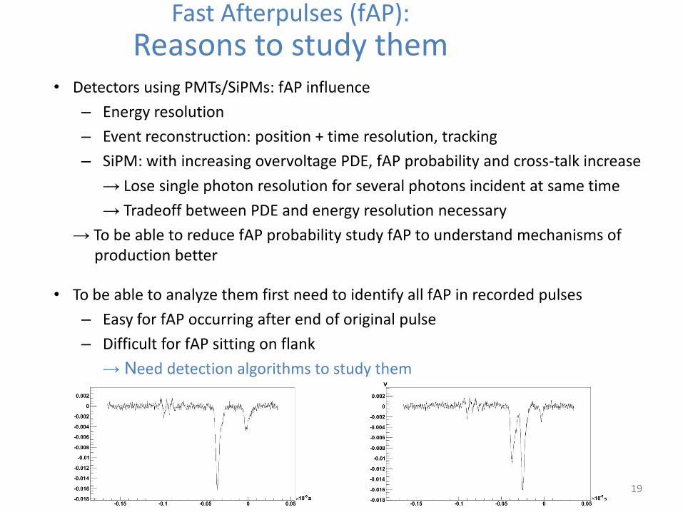
Fast Afterpulses (fAP):
Reasons to study them
• To be able to analyze them first need to identify all fAP in recorded pulses
– Easy for fAP occurring after end of original pulse
– Difficult for fAP sitting on flank
→ Need detection algorithms to study them
• Used 50000 pulses to develop algorithms • Instrumentation:
• Light source: Edinburgh Instruments EPL-405-mod, 50ps FWHM diode laser, 403nm
• PMT: ETL 9305 (+1300V), ≈5.5% detected pulses/laser trigger → ≈2.75% 2-photon-pulses for pulses with laser-PMT coincidence
• FADC: Acqiris DC282, used 2Ch with 4GHz sampling, 10bit
• Sampled 1500 pulses by eye → • ≈4.9% fAP on flank of main pulse
• ≈2.1% after main pulse within 70ns
• Different classes based on recognition criteria: • Time
• Pulse shape
• Area
• Was treated in a Bachelor thesis by Martin Zeitlmair
20
Fast Afterpulses (fAP):
Algorithms to detect fast Afterpulses on the flank of a previous pulse
Fast Afterpulses (fAP):
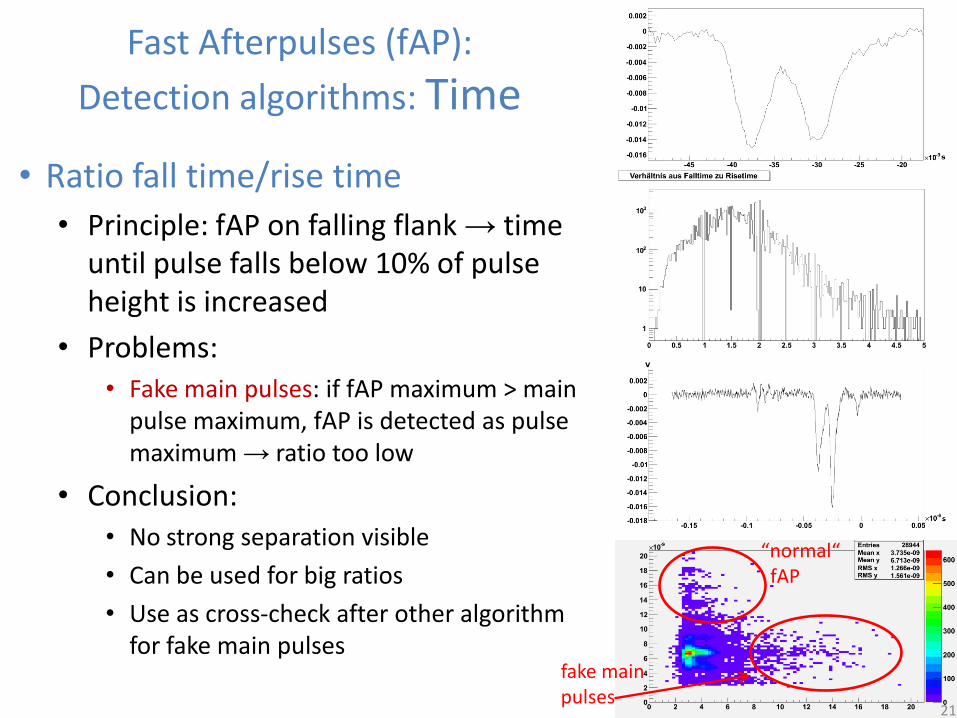
Detection algorithms: Time
• Ratio fall time/rise time
• Principle: fAP on falling flank → time until pulse falls below 10% of pulse height is increased
• Problems: • Fake main pulses: if fAP maximum > main
pulse maximum, fAP is detected as pulse maximum → ratio too low
• Conclusion: • No strong separation visible
• Can be used for big ratios
• Use as cross-check after other algorithm for fake main pulses
21
fake main pulses
“normal“ fAP
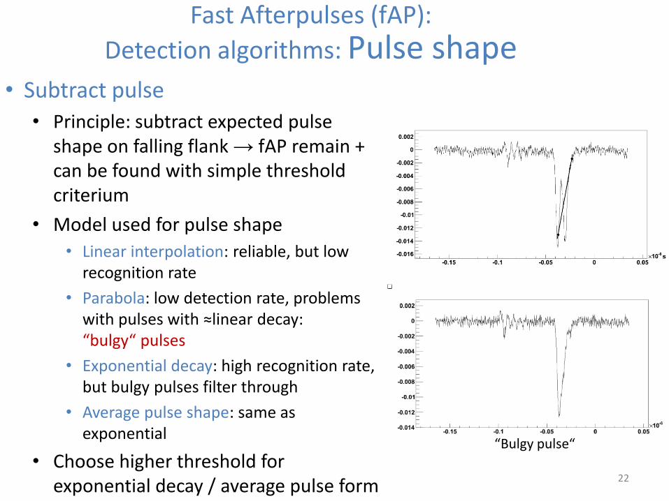
• Subtract pulse
• Principle: subtract expected pulse shape on falling flank → fAP remain + can be found with simple threshold criterium
• Model used for pulse shape
• Linear interpolation: reliable, but low recognition rate
• Parabola: low detection rate, problems with pulses with ≈linear decay: “bulgy“ pulses
• Exponential decay: high recognition rate, but bulgy pulses filter through
• Average pulse shape: same as exponential
• Choose higher threshold for exponential decay / average pulse form
22
Fast Afterpulses (fAP):
Detection algorithms: Pulse shape
“Bulgy pulse“
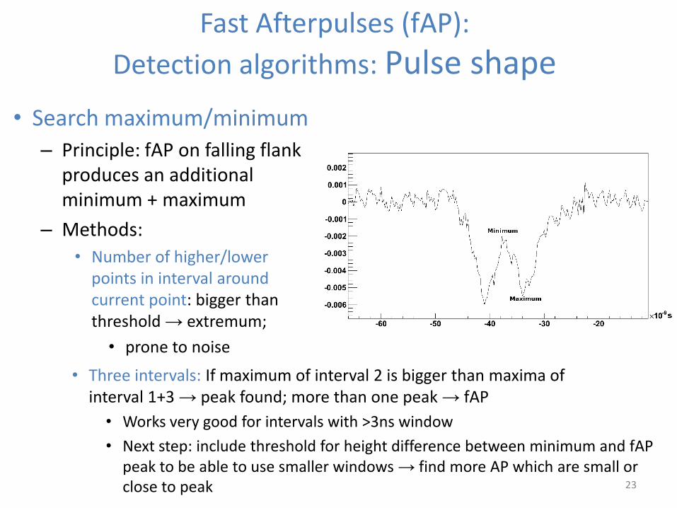
• Three intervals: If maximum of interval 2 is bigger than maxima of interval 1+3 → peak found; more than one peak → fAP
• Works very good for intervals with >3ns window
• Next step: include threshold for height difference between minimum and fAP peak to be able to use smaller windows → find more AP which are small or close to peak 23
Fast Afterpulses (fAP):
Detection algorithms: Pulse shape
• Search maximum/minimum
– Principle: fAP on falling flank produces an additional minimum + maximum
– Methods:
• Number of higher/lower points in interval around current point: bigger than threshold → extremum;
• prone to noise
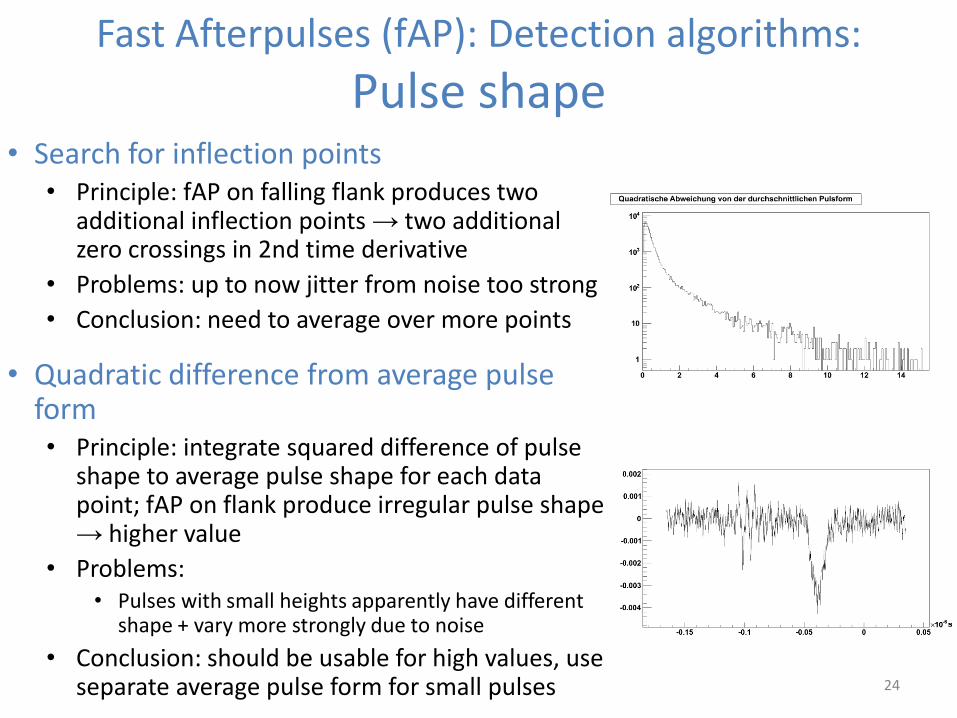
• Search for inflection points • Principle: fAP on falling flank produces two
additional inflection points → two additional zero crossings in 2nd time derivative
• Problems: up to now jitter from noise too strong
• Conclusion: need to average over more points
• Quadratic difference from average pulse form • Principle: integrate squared difference of pulse
shape to average pulse shape for each data point; fAP on flank produce irregular pulse shape → higher value
• Problems: • Pulses with small heights apparently have different
shape + vary more strongly due to noise
• Conclusion: should be usable for high values, use separate average pulse form for small pulses 24
Fast Afterpulses (fAP): Detection algorithms:
Pulse shape
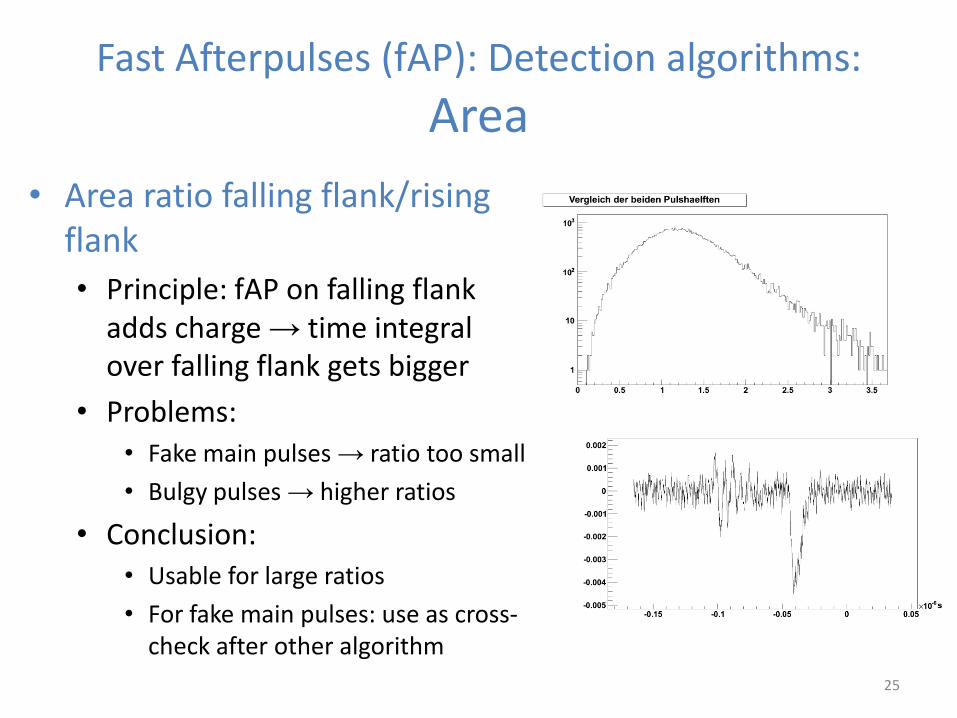
• Area ratio falling flank/rising flank
• Principle: fAP on falling flank adds charge → time integral over falling flank gets bigger
• Problems: • Fake main pulses → ratio too small
• Bulgy pulses → higher ratios
• Conclusion: • Usable for large ratios
• For fake main pulses: use as cross-check after other algorithm
25
Fast Afterpulses (fAP): Detection algorithms:
Area
Summary
• Pressure withstanding PMT encapsulations for LENA:
• Have designed engineering drawings of first encapsulations in CAD + simulated them with FEA software; method established → now refine it
• Results still very preliminary, need to construct complete optical module and optimize for weight + costs before comparisons between different designs are possible
• First results look promising
• Fast afterpulse detection algorithms
• Developed several algorithms, identified problems
• Still optimizing to eliminate disturbing effects and increase detection rate
• With only small adjustments and combined evaluation of two methods, most algorithms should improve substantially
26

References
• For further information please refer to:
• LENA White Paper, http://arxiv.org/abs/1104.5620
• German Beischler, bachelor thesis, Technische Universität München, August 2011, http://www.e15.physik.tu-muenchen.de/fileadmin/downloads/thesis/bachelor/2011_BSc_German_Beischler.pdf
• Martin Zeitlmair, bachelor thesis, Teschnische Universität München, July 2011, http://www.e15.physik.tu-muenchen.de/fileadmin/downloads/thesis/bachelor/2011_BSc_Martin_Zeitlmair.pdf
27
Backup slides
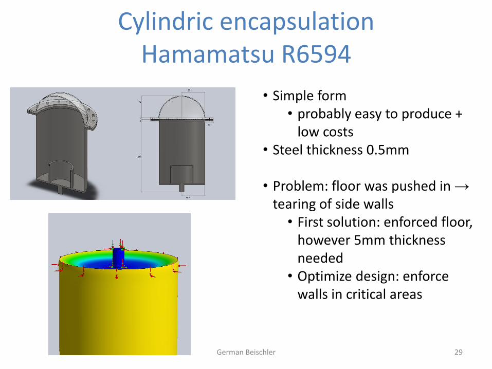
Cylindric encapsulation Hamamatsu R6594
German Beischler 29
• Simple form • probably easy to produce +
low costs • Steel thickness 0.5mm
• Problem: floor was pushed in →
tearing of side walls • First solution: enforced floor,
however 5mm thickness needed
• Optimize design: enforce walls in critical areas
Assembly of a R6594 conical encapsulation
German Beischler 30
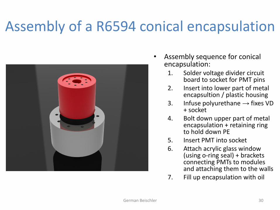
• Assembly sequence for conical encapsulation:
1. Solder voltage divider circuit board to socket for PMT pins
2. Insert into lower part of metal encapsultion / plastic housing
3. Infuse polyurethane → fixes VD + socket
4. Bolt down upper part of metal encapsulation + retaining ring to hold down PE
5. Insert PMT into socket 6. Attach acrylic glass window
(using o-ring seal) + brackets connecting PMTs to modules and attaching them to the walls
7. Fill up encapsulation with oil
Assembly of a R6594 conical encapsulation
German Beischler 31
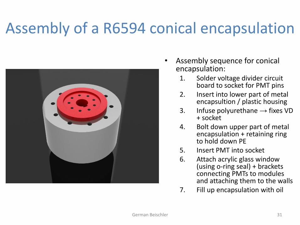
• Assembly sequence for conical encapsulation:
1. Solder voltage divider circuit board to socket for PMT pins
2. Insert into lower part of metal encapsultion / plastic housing
3. Infuse polyurethane → fixes VD + socket
4. Bolt down upper part of metal encapsulation + retaining ring to hold down PE
5. Insert PMT into socket 6. Attach acrylic glass window
(using o-ring seal) + brackets connecting PMTs to modules and attaching them to the walls
7. Fill up encapsulation with oil
Assembly of a R6594 conical encapsulation
German Beischler 32
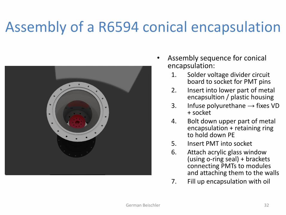
• Assembly sequence for conical encapsulation:
1. Solder voltage divider circuit board to socket for PMT pins
2. Insert into lower part of metal encapsultion / plastic housing
3. Infuse polyurethane → fixes VD + socket
4. Bolt down upper part of metal encapsulation + retaining ring to hold down PE
5. Insert PMT into socket 6. Attach acrylic glass window
(using o-ring seal) + brackets connecting PMTs to modules and attaching them to the walls
7. Fill up encapsulation with oil
Assembly of a R6594 conical encapsulation
German Beischler 33
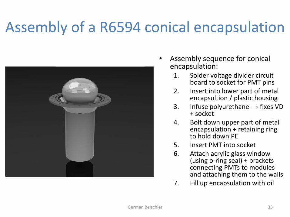
• Assembly sequence for conical encapsulation:
1. Solder voltage divider circuit board to socket for PMT pins
2. Insert into lower part of metal encapsultion / plastic housing
3. Infuse polyurethane → fixes VD + socket
4. Bolt down upper part of metal encapsulation + retaining ring to hold down PE
5. Insert PMT into socket 6. Attach acrylic glass window
(using o-ring seal) + brackets connecting PMTs to modules and attaching them to the walls
7. Fill up encapsulation with oil
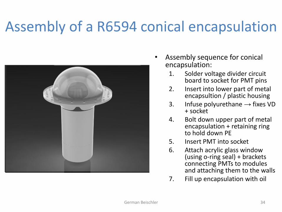
Assembly of a R6594 conical encapsulation
German Beischler 34
• Assembly sequence for conical encapsulation:
1. Solder voltage divider circuit board to socket for PMT pins
2. Insert into lower part of metal encapsultion / plastic housing
3. Infuse polyurethane → fixes VD + socket
4. Bolt down upper part of metal encapsulation + retaining ring to hold down PE
5. Insert PMT into socket 6. Attach acrylic glass window
(using o-ring seal) + brackets connecting PMTs to modules and attaching them to the walls
7. Fill up encapsulation with oil
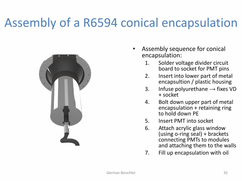
Assembly of a R6594 conical encapsulation
German Beischler 35
• Assembly sequence for conical encapsulation:
1. Solder voltage divider circuit board to socket for PMT pins
2. Insert into lower part of metal encapsultion / plastic housing
3. Infuse polyurethane → fixes VD + socket
4. Bolt down upper part of metal encapsulation + retaining ring to hold down PE
5. Insert PMT into socket 6. Attach acrylic glass window
(using o-ring seal) + brackets connecting PMTs to modules and attaching them to the walls
7. Fill up encapsulation with oil
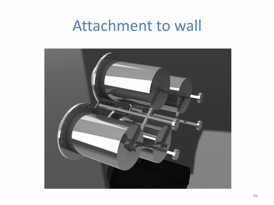
Attachment to wall
36