Embed Size (px)
Citation preview
TAKENAKA TECHNICAL RESEARCH REPORT No.76 2020
Development of a Damping System that Reduce the Vibration of the Chandelier
Takahiro Kinoshita*1 Takayuki Sone*2 Masanori Iida*3
Tsutomu Yokonami*4 Kenta Nagahama*5
Summary
The authors proposed two types of damping systems that can reduce the response of chandeliers. The feature of these systems is that the energy dissipation system is placed only between the floor slab and the ceiling. Since this system is placed in the ceiling space, it does not distract from the appearance of the chandelier.
Shaking table tests of the proposed systems were performed and compared with the simulation by analytical model. The experimental results almost corresponded with the simulation by considering the effect of the friction of the dampers.
Keywords: chandelier, damping system, shaking table test, image analysis
1 Introduction
Damage to non-structural members is a form of seismic damage. The Great East Japan Earthquake, which occurred on March
11, 2011, caused large amounts of damage to ceilings and equipment 1),2), and the need for securing the seismic resistance in non-
structural members was recognized. Measures for the earthquake resistance of ceilings have been gradually systematized, but they
remain insufficient for other non-structural members.
In this study, a damping method for chandeliers is proposed. Chandeliers are often installed in large spaces with an atrium or in
living rooms with high ceilings, and they have a longer suspension length than other equipment. Cases where the natural period of
the chandelier is close to that of the building may result in the chandelier resonating with the shaking of the building, resulting in
significant shaking of the chandelier. As the damping capacity of the chandelier itself is also low, it shakes easily during earthquakes
and takes a long time for the shaking to subside. The chandelier can make users of the building feel uneasy in the event of an
earthquake, and in the worst-case scenario, the chandelier may fall and injure users.
Seismic measures for chandeliers include a method for suppressing shaking by installing a damping material shown in reference
3). This method affects the appearance of the chandelier because the chandelier itself needs to be fixed with a damping material.
However, as chandeliers are largely valued for their aesthetics, such measures that affect their appearance are not desirable. The
strength of the chandelier itself when such damping material is fixed may also be insufficient, and this measure is not considered
effective.
Considering the facts mentioned, a damping system that could effectively add damping to the chandelier was devised. A feature
of this system is that countermeasures are limited between the ceiling slab and ceiling material, which allows for the shaking to be
effectively suppressed without disturbing the appearance of the chandelier. The following sections outline the proposed damping
system and derive the equation of motion. Next, the conditions for minimizing the amplitude ratio of the fixed points of the transfer
function are arranged based on the fixed points theory, and the effects are shown using the transfer function and time history
response analysis. Finally, the effects of this system are verified by using a shaking table test, and the validity is verified by
comparing with the analysis results. This system was developed mainly for chandeliers, but can also be applied to other suspended
objects.
*1 Researcher, Research & Development Institute *2 Chief Researcher, Research & Development Institute *3 Manager, Design Department, Nagoya Branch Office *4 Deputy Senior Manager, Design Department, Nagoya Branch Office *5 Associate Chief Researcher, Research & Development Institute
TAKENAKA TECHNICAL RESEARCH REPORT No.76 2020
2 Overview of the Damping System 2.1 Damping System Configuration
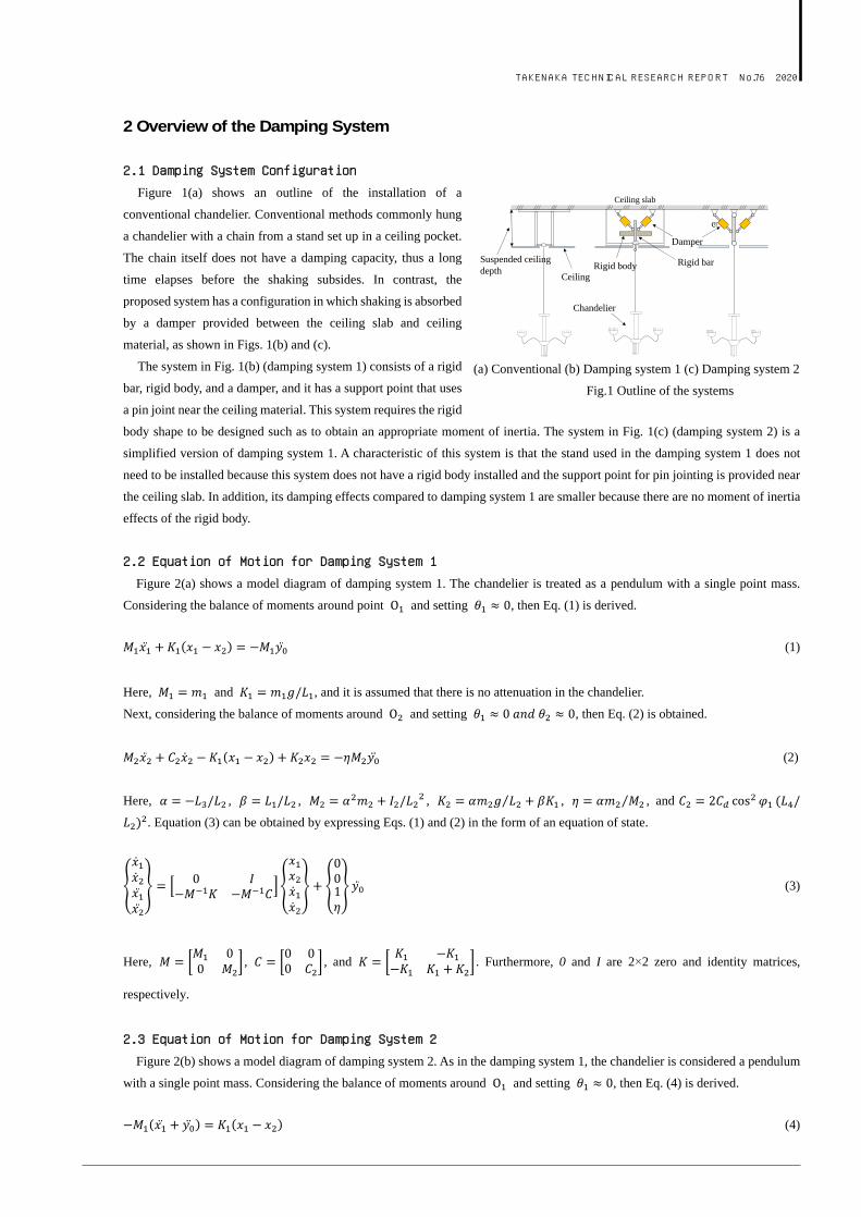
Figure 1(a) shows an outline of the installation of a
conventional chandelier. Conventional methods commonly hung
a chandelier with a chain from a stand set up in a ceiling pocket.
The chain itself does not have a damping capacity, thus a long
time elapses before the shaking subsides. In contrast, the
proposed system has a configuration in which shaking is absorbed
by a damper provided between the ceiling slab and ceiling
material, as shown in Figs. 1(b) and (c).
The system in Fig. 1(b) (damping system 1) consists of a rigid
bar, rigid body, and a damper, and it has a support point that uses
a pin joint near the ceiling material. This system requires the rigid
body shape to be designed such as to obtain an appropriate moment of inertia. The system in Fig. 1(c) (damping system 2) is a
simplified version of damping system 1. A characteristic of this system is that the stand used in the damping system 1 does not
need to be installed because this system does not have a rigid body installed and the support point for pin jointing is provided near
the ceiling slab. In addition, its damping effects compared to damping system 1 are smaller because there are no moment of inertia
effects of the rigid body.
2.2 Equation of Motion for Damping System 1
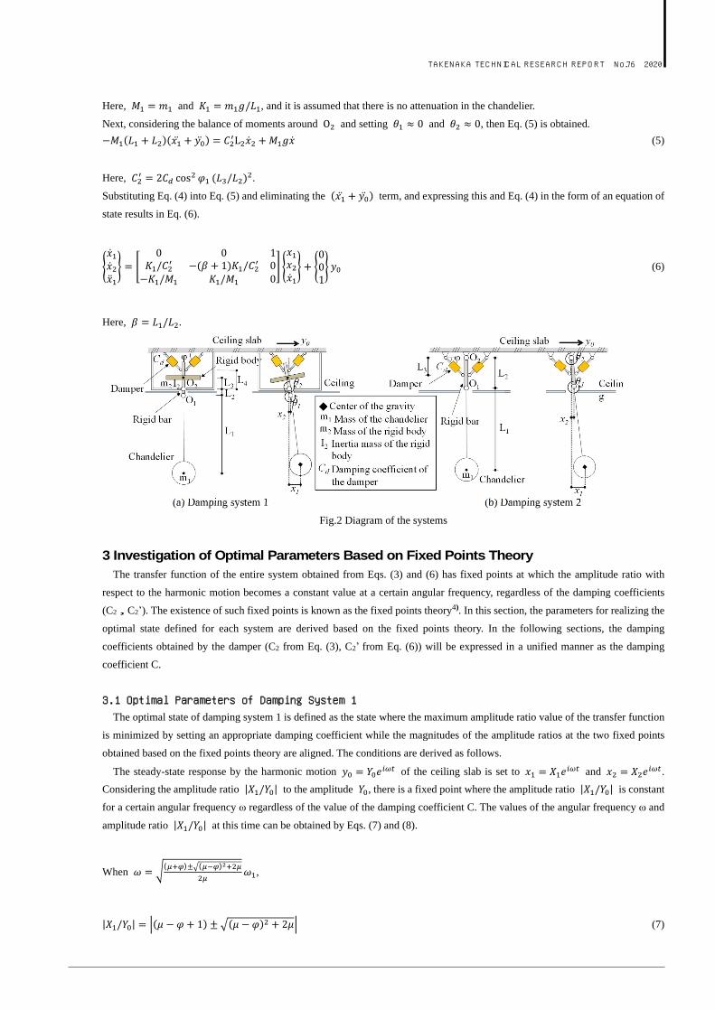
Figure 2(a) shows a model diagram of damping system 1. The chandelier is treated as a pendulum with a single point mass.
Considering the balance of moments around point and setting , then Eq. (1) is derived.
(1)
Here, and , and it is assumed that there is no attenuation in the chandelier.
Next, considering the balance of moments around and setting , then Eq. (2) is obtained.
(2)
Here, , , , , , and
. Equation (3) can be obtained by expressing Eqs. (1) and (2) in the form of an equation of state.
(3)
Here, , , and . Furthermore, 0 and I are 2×2 zero and identity matrices,
respectively.
2.3 Equation of Motion for Damping System 2
Figure 2(b) shows a model diagram of damping system 2. As in the damping system 1, the chandelier is considered a pendulum
with a single point mass. Considering the balance of moments around and setting , then Eq. (4) is derived.
(4)
(a) Conventional (b) Damping system 1 (c) Damping system 2
Fig.1 Outline of the systems
Ceiling slab
cd
Rigid body Rigid bar
Damper
Ceiling
Chandelier
Suspended ceiling depth
TAKENAKA TECHNICAL RESEARCH REPORT No.76 2020
Here, and , and it is assumed that there is no attenuation in the chandelier.
Next, considering the balance of moments around and setting and , then Eq. (5) is obtained.
(5)
Here, .
Substituting Eq. (4) into Eq. (5) and eliminating the term, and expressing this and Eq. (4) in the form of an equation of
state results in Eq. (6).
(6)
Here, .
(a) Damping system 1 (b) Damping system 2
Fig.2 Diagram of the systems
3 Investigation of Optimal Parameters Based on Fixed Points Theory The transfer function of the entire system obtained from Eqs. (3) and (6) has fixed points at which the amplitude ratio with
respect to the harmonic motion becomes a constant value at a certain angular frequency, regardless of the damping coefficients
(C2,C2’). The existence of such fixed points is known as the fixed points theory4). In this section, the parameters for realizing the
optimal state defined for each system are derived based on the fixed points theory. In the following sections, the damping
coefficients obtained by the damper (C2 from Eq. (3), C2’ from Eq. (6)) will be expressed in a unified manner as the damping
coefficient C.
3.1 Optimal Parameters of Damping System 1 The optimal state of damping system 1 is defined as the state where the maximum amplitude ratio value of the transfer function
is minimized by setting an appropriate damping coefficient while the magnitudes of the amplitude ratios at the two fixed points
obtained based on the fixed points theory are aligned. The conditions are derived as follows.
The steady-state response by the harmonic motion of the ceiling slab is set to and .
Considering the amplitude ratio to the amplitude , there is a fixed point where the amplitude ratio is constant
for a certain angular frequency ω regardless of the value of the damping coefficient C. The values of the angular frequency ω and
amplitude ratio at this time can be obtained by Eqs. (7) and (8).
When ( )± ( )
,
(7)
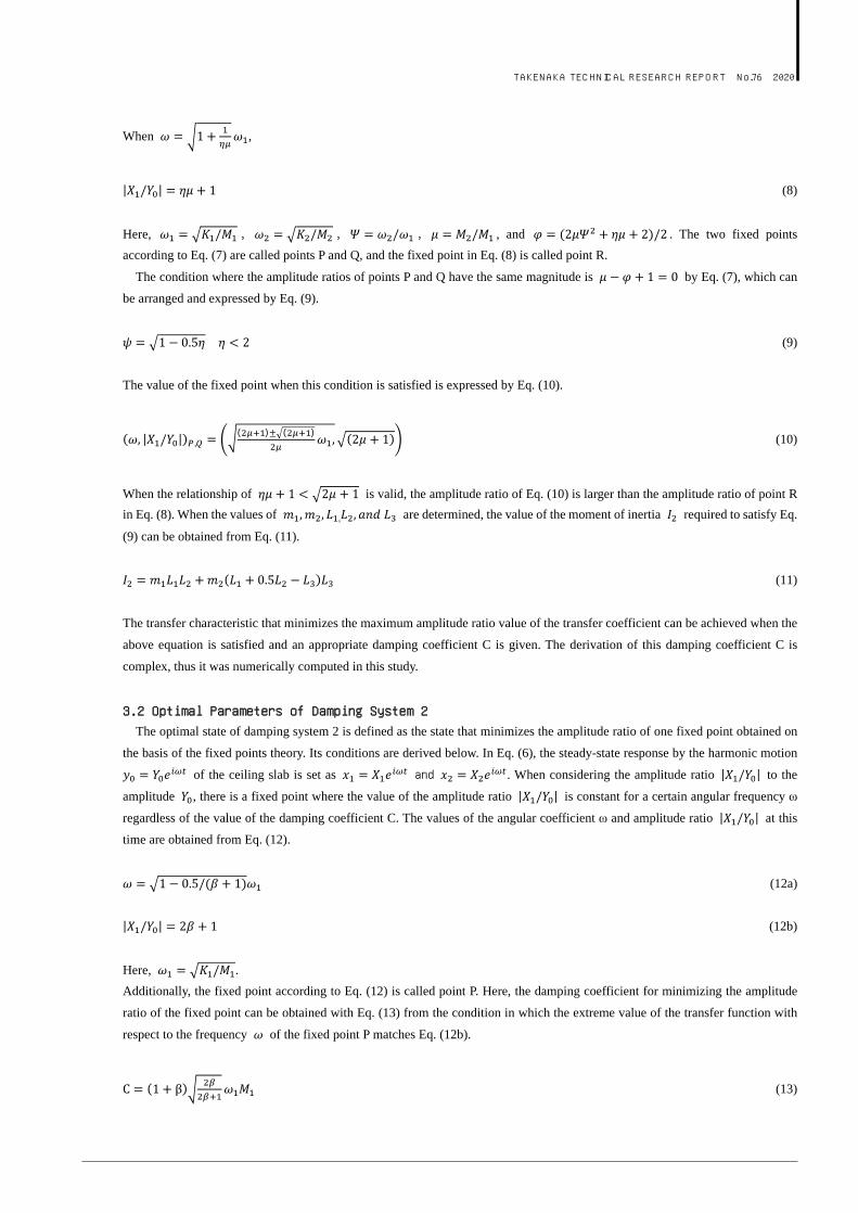
TAKENAKA TECHNICAL RESEARCH REPORT No.76 2020
When ,
(8)
Here, , , , , and . The two fixed points
according to Eq. (7) are called points P and Q, and the fixed point in Eq. (8) is called point R.
The condition where the amplitude ratios of points P and Q have the same magnitude is by Eq. (7), which can
be arranged and expressed by Eq. (9).
(9)
The value of the fixed point when this condition is satisfied is expressed by Eq. (10).
,( )± ( )
(10)
When the relationship of is valid, the amplitude ratio of Eq. (10) is larger than the amplitude ratio of point R
in Eq. (8). When the values of , are determined, the value of the moment of inertia required to satisfy Eq.
(9) can be obtained from Eq. (11).
(11)
The transfer characteristic that minimizes the maximum amplitude ratio value of the transfer coefficient can be achieved when the
above equation is satisfied and an appropriate damping coefficient C is given. The derivation of this damping coefficient C is
complex, thus it was numerically computed in this study.
3.2 Optimal Parameters of Damping System 2 The optimal state of damping system 2 is defined as the state that minimizes the amplitude ratio of one fixed point obtained on
the basis of the fixed points theory. Its conditions are derived below. In Eq. (6), the steady-state response by the harmonic motion
of the ceiling slab is set as and . When considering the amplitude ratio to the
amplitude , there is a fixed point where the value of the amplitude ratio is constant for a certain angular frequency ω
regardless of the value of the damping coefficient C. The values of the angular coefficient ω and amplitude ratio at this
time are obtained from Eq. (12).
(12a)
(12b)
Here, .
Additionally, the fixed point according to Eq. (12) is called point P. Here, the damping coefficient for minimizing the amplitude
ratio of the fixed point can be obtained with Eq. (13) from the condition in which the extreme value of the transfer function with
respect to the frequency of the fixed point P matches Eq. (12b).
(13)
TAKENAKA TECHNICAL RESEARCH REPORT No.76 2020
4 Analytical Investigation of Damping Effects In this section, the characteristics of this system are confirmed using the transfer function of the study model, and the damping
effects are verified by time history response analysis.
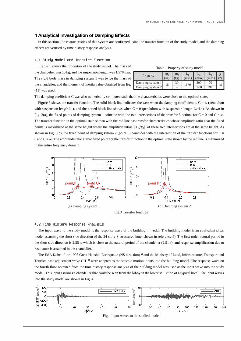
4.1 Study Model and Transfer Function
Table 1 shows the properties of the study model. The mass of
the chandelier was 15 kg, and the suspension length was 1,570 mm.
The rigid body mass in damping system 1 was twice the mass of
the chandelier, and the moment of inertia value obtained from Eq.
(11) was used.
The damping coefficient C was also numerically computed such that the characteristics were close to the optimal state.
Figure 3 shows the transfer function. The solid black line indicates the case when the damping coefficient is C = ∞ (pendulum
with suspension length L1), and the dotted black line shows when C = 0 (pendulum with suspension length L1+L2). As shown in
Fig. 3(a), the fixed points of damping system 1 coincide with the two intersections of the transfer functions for C = 0 and C = ∞.
The transfer function in the optimal state shown with the red line has transfer characteristics whose amplitude ratio near the fixed
points is maximized at the same height where the amplitude ratios of these two intersections are at the same height. As
shown in Fig. 3(b), the fixed point of damping system 2 (point P) coincides with the intersection of the transfer functions for C =
0 and C = ∞. The amplitude ratio at that fixed point for the transfer function in the optimal state shown by the red line is maximized
in the entire frequency domain.
(a) Damping system 1 (b) Damping system 2
Fig.3 Transfer function
4.2 Time History Response Analysis
The input wave to the study model is the response wave of the building m odel. The building model is an equivalent shear
model assuming the short side direction of the 24-story S-structured hotel shown in reference 5). The first-order natural period in
the short side direction is 2.55 s, which is close to the natural period of the chandelier (2.51 s), and response amplification due to
resonance is assumed in the chandelier.
The JMA Kobe of the 1995 Great Hanshin Earthquake (NS direction) 6) and the Ministry of Land, Infrastructure, Transport and
Tourism base adjustment wave CH17) were adopted as the seismic motion inputs into the building model. The response wave on
the fourth floor obtained from the time history response analysis of the building model was used as the input wave into the study
model. This input assumes a chandelier that could be seen from the lobby in the lower se ction of a typical hotel. The input waves
into the study model are shown in Fig. 4.
Fig.4 Input waves to the studied model
加速度(cm/s2)
Acc.(cm/s2 )
Amp.¦X1/Y0¦
Amp.¦X1/Y0¦
point P point P point Q
Table 1 Property of study model
Propertym1
(kg)m2
(kg)L1
(mm)L2
(mm)L3
(mm)φ(°)
Damping sy stem 1 30 200 70Damping sy stem 2 - 600 300
15 1570 45
TAKENAKA TECHNICAL RESEARCH REPORT No.76 2020
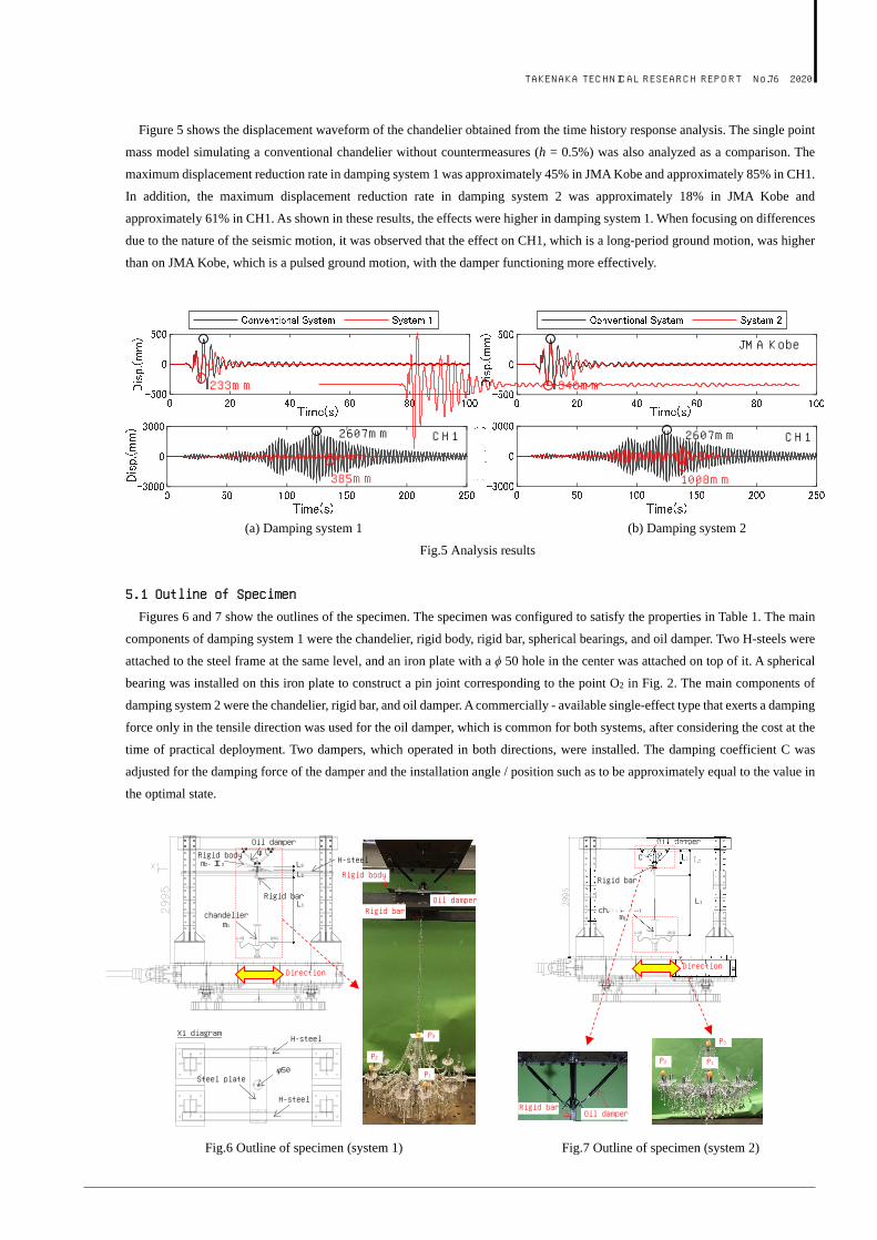
Figure 5 shows the displacement waveform of the chandelier obtained from the time history response analysis. The single point
mass model simulating a conventional chandelier without countermeasures (h = 0.5%) was also analyzed as a comparison. The
maximum displacement reduction rate in damping system 1 was approximately 45% in JMA Kobe and approximately 85% in CH1.
In addition, the maximum displacement reduction rate in damping system 2 was approximately 18% in JMA Kobe and
approximately 61% in CH1. As shown in these results, the effects were higher in damping system 1. When focusing on differences
due to the nature of the seismic motion, it was observed that the effect on CH1, which is a long-period ground motion, was higher
than on JMA Kobe, which is a pulsed ground motion, with the damper functioning more effectively.
(a) Damping system 1 (b) Damping system 2
Fig.5 Analysis results
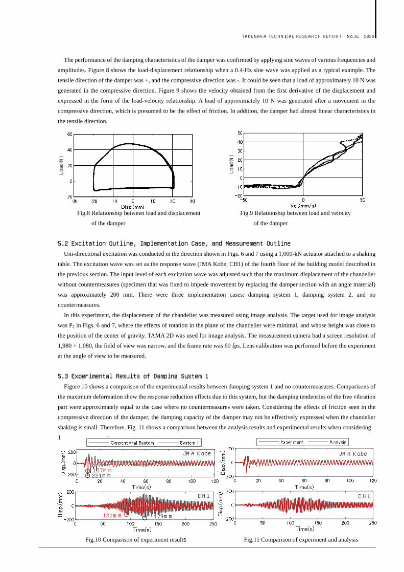
5.1 Outline of Specimen
Figures 6 and 7 show the outlines of the specimen. The specimen was configured to satisfy the properties in Table 1. The main
components of damping system 1 were the chandelier, rigid body, rigid bar, spherical bearings, and oil damper. Two H-steels were
attached to the steel frame at the same level, and an iron plate with a ϕ 50 hole in the center was attached on top of it. A spherical
bearing was installed on this iron plate to construct a pin joint corresponding to the point O2 in Fig. 2. The main components of
damping system 2 were the chandelier, rigid bar, and oil damper. A commercially - available single-effect type that exerts a damping
force only in the tensile direction was used for the oil damper, which is common for both systems, after considering the cost at the
time of practical deployment. Two dampers, which operated in both directions, were installed. The damping coefficient C was
adjusted for the damping force of the damper and the installation angle / position such as to be approximately equal to the value in
the optimal state.
Fig.6 Outline of specimen (system 1) Fig.7 Outline of specimen (system 2)
JMA Kobe JMA 神戸 423mm 423mm
233mm 346mm
2607mm 2607mm CH1
JMA Kobe
CH1
385mm 1008mm
Oil damper
chandelier
Rigid bar
L1
L2 L3 φ C
m1
Direction
Oil damper Rigid bar
P2 P1
P3
Rigid bar
Rigid body
P1
Oil damper
Rigid body
L1
L2 L3
φ
m1
Direction
chandelier
Rigid bar
m2、I2
H-steel
H-steel
φ50 Steel plate
X1 diagram
H-steel
P3
P2
Oil damper
TAKENAKA TECHNICAL RESEARCH REPORT No.76 2020
The performance of the damping characteristics of the damper was confirmed by applying sine waves of various frequencies and
amplitudes. Figure 8 shows the load-displacement relationship when a 0.4-Hz sine wave was applied as a typical example. The
tensile direction of the damper was +, and the compressive direction was -. It could be seen that a load of approximately 10 N was
generated in the compressive direction. Figure 9 shows the velocity obtained from the first derivative of the displacement and
expressed in the form of the load-velocity relationship. A load of approximately 10 N was generated after a movement in the
compressive direction, which is presumed to be the effect of friction. In addition, the damper had almost linear characteristics in
the tensile direction.
Fig.8 Relationship between load and displacement Fig.9 Relationship between load and velocity
of the damper of the damper
5.2 Excitation Outline, Implementation Case, and Measurement Outline
Uni-directional excitation was conducted in the direction shown in Figs. 6 and 7 using a 1,000-kN actuator attached to a shaking
table. The excitation wave was set as the response wave (JMA Kobe, CH1) of the fourth floor of the building model described in
the previous section. The input level of each excitation wave was adjusted such that the maximum displacement of the chandelier
without countermeasures (specimen that was fixed to impede movement by replacing the damper section with an angle material)
was approximately 200 mm. There were three implementation cases: damping system 1, damping system 2, and no
countermeasures.
In this experiment, the displacement of the chandelier was measured using image analysis. The target used for image analysis
was P2 in Figs. 6 and 7, where the effects of rotation in the plane of the chandelier were minimal, and whose height was close to
the position of the center of gravity. TAMA 2D was used for image analysis. The measurement camera had a screen resolution of
1,980 × 1,080, the field of view was narrow, and the frame rate was 60 fps. Lens calibration was performed before the experiment
at the angle of view to be measured.
5.3 Experimental Results of Damping System 1
Figure 10 shows a comparison of the experimental results between damping system 1 and no countermeasures. Comparisons of
the maximum deformation show the response reduction effects due to this system, but the damping tendencies of the free vibration
part were approximately equal to the case where no countermeasures were taken. Considering the effects of friction seen in the
compressive direction of the damper, the damping capacity of the damper may not be effectively expressed when the chandelier
shaking is small. Therefore, Fig. 11 shows a comparison between the analysis results and experimental results when considering
1
Fig.10 Comparison of experiment results Fig.11 Comparison of experiment and analysis
Load(N)
Load(N)
JMA Kobe
CH1
137mm 221mm
CH1
121mm 179mm
JMA Kobe
TAKENAKA TECHNICAL RESEARCH REPORT No.76 2020
the friction of the damper. It can be seen that the phase and maximum displacement of the free vibration part could be effectively
reproduced by analysis.
5.4 Experimental Results of Damping System 2
Figure 12 shows a comparison of the experimental results between damping system 2 and no countermeasures. Comparisons of
the maximum deformation showed that the JMA Kobe results had a small effect, but that the CH1 decreased the value to
approximately half. Moreover, the expected effects may have been insufficiently obtained during small amplitudes, similar to the
case in damping system 1, due to the friction effects of the damper.
It was mentioned in the previous section that the experiment and analysis results were consistent with each other by considering
the effects of friction in the analysis. Similar tendencies could be confirmed in damping system 2 as well, but comparisons by the
transfer function are also important for confirming the characteristics of specimens. However, the time of the free vibration part
was extremely long due to the friction effects of the damper, and the transfer function could not be clearly obtained from the fast
Fourier transform of the displacement waveform. Therefore, the shaking table was vibrated with a sine wave in damping system 2,
and the transfer function was obtained from the displacement ratios of the chandelier and shaking table when the specimen was in
a steady state. This was then compared with the analysis results. The frequency of the sine wave fluctuated from 0.2 to 0.5 Hz in
0.01-Hz increments. Figure 13 shows the transfer function obtained from analyses and the experimental results. The experimental
results could effectively reproduce the specimen characteristics, and it was confirmed that they were consistent with the theoretical
values when the amplitude of the chandelier was large and the friction effects were relatively small.
Fig.12 Comparison of experiment results Fig.13 Comparison of transfer function
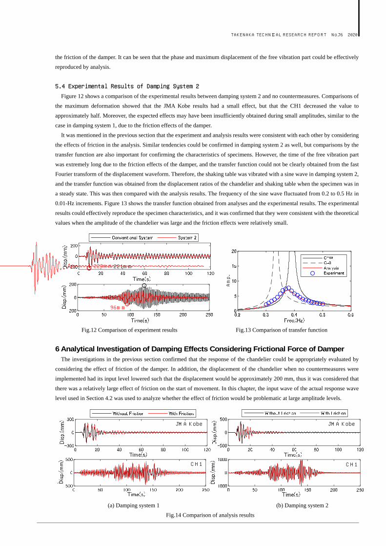
6 Analytical Investigation of Damping Effects Considering Frictional Force of Damper The investigations in the previous section confirmed that the response of the chandelier could be appropriately evaluated by
considering the effect of friction of the damper. In addition, the displacement of the chandelier when no countermeasures were
implemented had its input level lowered such that the displacement would be approximately 200 mm, thus it was considered that
there was a relatively large effect of friction on the start of movement. In this chapter, the input wave of the actual response wave
level used in Section 4.2 was used to analyze whether the effect of friction would be problematic at large amplitude levels.
(a) Damping system 1 (b) Damping system 2
Fig.14 Comparison of analysis results
Amp.
JMA 神戸
223mm 221mm
CH1 179mm
96mm
JMA Kobe JMA Kobe
CH1 CH1
TAKENAKA TECHNICAL RESEARCH REPORT No.76 2020
Figure 14 shows a comparison of the analysis results with and without the friction of the damper. The input ground motion was
set as a response wave on the fourth floor of the building model used in Section 4.2. There were no major differences in the response
in damping system 1 compared to when the large amplitude part was not considered, but the effect of friction was large in the small
amplitude part, represented by the free vibration part. This tendency did not change for damping system 2 as well. The effect
assumed in the analysis could be expected in the large amplitude area considering the friction level of the damper used in this study.
7 Conclusions In this report, a damping system that reduces the shaking during an earthquake without negatively affecting the aesthetic
appearance of a chandelier is proposed. The damping effects were verified using a time history response analysis and shaking table
test. The conclusions are shown below. (1) The equations of motion for the two proposed damping systems are shown, and the parameters that are in the optimal state
are shown for each of the equations;
(2) Investigations of the damping effects by time history response analysis showed that the effects on the long-period ground
motion of CH1 were higher than on the pulsed ground motion of JMA Kobe. The maximum displacement reduction rate at
this time was approximately 85% at its highest;
(3) The shaking table test and analysis results were compared. The friction effects of the damper in the analysis effectively
captured the experimental result tendencies;
(4) The friction effects of the damper were confirmed to be minimal in the large amplitude area based on analytical investigations
of the actual response wave level. It is considered that using a damper with small frictional force increased the damping effects
at small amplitudes. In addition, the optimal damper should be selected considering the cost-effectiveness and the cost of the
chandelier.
References
1) Architectural Institute of Japan: Great East Japan Earthquake Joint Survey Report, Architecture Edition 6, Non-Structural
Members, 2019.
2) Architectural Institute of Japan: Research on the Mitigation of Damage by Earthquakes and Wind on Non-Structural Members
(Roof, Outer Wall, Ceiling), 2008.
3) Japan Building Equipment and Elevator Center Foundation: Building Equipment / Elevator Seismic Diagnosis Standards and
Repair Guidelines, 1996.
4)J. P. Den Hartog: Mechanical Vibration, 4th edition, McGraw-Hill, New York, 1956
5)T. Kinoshita, et al.: PROPOSAL OF DAMPING SYSTEMS FOR CHANDELIERS. 16th World Conference on Seismic Isolation,
1-6 July 2019, Saint Petersburg, Russia
6) Japan Meteorological Agency: Strong Earthquake Waveform (1995 Great Hanshin Earthquake),
https://www.data.jma.go.jp/svd/eqev/data/kyoshin/jishin/hyogo_nanbu/index.html (last accessed 2020.08.05).
7) Building Research Institute: Special Page for Disclosure of Technical Materials / Data related to Long-Period Ground Motion
Countermeasures, https://www.kenken.go.jp/japanese/contents/topics/lpe/index.html (last accessed 2020.08.05).


![GODO VIBRATION MOTOR [호환 모드] - Gobizkoreagodoelec.koreasme.com/en/download/GODO VIBRATION MOTOR.pdf · INTRODUCTION Vibration Motor – Bar type Bar type vibration motor is](https://img.pdfslide.tips/doc/110x75/5abdb7cd7f8b9aa3088bfaa7/godo-vibration-motor-vibration-motorpdfintroduction-vibration.jpg)