Embed Size (px)
Citation preview

Diesel United-S.E.M.T. PIELSTICKMedium - Speed Engines
IMO NOx Tier - Ⅱ
Diesel United-S.E.M.T. PIELSTICKMedium - Speed Engines
IMO NOx Tier - Ⅱ

0 10000 20000 2500015000 30000kW
PC2-6B
PC2-6
PC4-2B
出力範囲Power Range
DU-S.E.M.T. Pielstick エンジンは、S.E.M.T. 社(現 MAN Diesel SAS 社)の開発したコンパクトかつ高出力のエンジンで、1964年のS.E.M.T.社(仏)との技術提携以来、国内外で数多くの納入実績を持っております。その歴史は古く、1946 年、ディーゼル設計会社、SOCIETE D’ETUDES DES MACHINES THERMIQUES (S.E.M.T.) 社がパリに設立され、以来「低速エンジンより軽くコンパクトなディーゼルエンジン」という目標の下にS.E.M.T.社の研究開発が始まりました。1963 年、S.E.M.T. 社において、重油を燃料とすることができた初めての中速エンジン、PC2 形エンジンが開発され、その翌年(1964年)、DUの設立母体である石川島播磨重工業(現在の株式会社 IHI)がS.E.M.T.社と技術提携を結びました。1965年にDU-S.E.M.T. 形初号機8PC2V(2,560PS×330min-1)が船舶用主機として完成、IHI のフリーダム船に採用され 1966 年にその初号機 12PC2V(5,130PS×500min-1)が完成するに至りました。1970年、シリンダ当り出力を増加しPC4形の開発がS.E.M.T.社と共同で始まり、1974年に12PC4V(12.8MW×400min-1)が、構内に建設された発電所で稼動を開始しました。PC2 形、PC4 形エンジンは、これ以降マーケットのニーズに応え、順次出力を上げ、燃費の改善、さらには排ガスエミッションの改善と進化を重ねてきました。
DU-S.E.M.T. Pielstick diesel engines are designed by S.E.M.T. ( present, MAN Diesel SAS ), and, after the license agreement with S.E.M.T. (France) in 1964, Diesel United has introduced a lot of engines to not only Japan but also overseas countries, S.E.M.T. Pielstick diesel engines continues the long tradition.In 1946 a design company of diesel engines, SOCIETE D’ETUDES DES MACHINES THERMIQUES (S.E.M.T.) was established in Paris and started for the development of lighter and more compact diesel engines than the low-speed engines.In 1963 S.E.M.T. developed PC-2 type engine and it was the world first engine which could use heavy fuel oil, and in the next year (1964) Ishikawajima-Harima (present IHI Ltd.), our parent company, made the technical license agreement with S.E.M.T.The first DU-S.E.M.T. 8PC2V (2,560PS×330min-1) was applied for the Freedom series of IHI designed bulk carrier in 1965 and then 12PC2V (5,130PS×500min-1) came to be completed in 1966.DU started to develop PC4 type engine which increased the output for each cylinder together with S.E.M.T. in 1970. And in 1974 12PC4V (12.8MW×400min-1) began operating at the power plant in our works. PC2 type and PC4 type engines sequentially increased the output, improved the fuel consumption and reduced the exhaust gas emission to meet with the market needs.
DU-S.E.M.T. Pielstick engines
2 3
環境規制対応についてNOx Emission of IMO Tier-Ⅱ
IMO NOx二次規制が、2011年1月1日以降建造の船に適用が義務化されます。本カタログに記載されている DU-PCエンジンは全て、IMO NOx二次規制に対応しています。
IMO NOx Tier-Ⅱwill be mandatory applied for the ships constructed on or after 1 January 2011.All engines in this catalogue can comply with upcoming IMO NOx Tier-Ⅱ emission regulations.
PC2
PC2形エンジン
PC4形エンジン
PC2-1PC2-2
PC4
PC2-5
PC40L
PC40L
PC4-2B
PC4-2B
PC4-2
PC2-5PC2-6
PC2-6B
PC2-6B600
(480)(550)
(750)
(650)
(1215)
(1325)
(1100)
PC形エンジンの変遷History of PC engines
西 暦(年)Year
1960 1965 1970 1975 1980 1985 1990 1995 2000 2005 2010
1400
1200
1000
800
600
400
200
シリンダ当り出力(Wk)
Output per cylinder
16PC2-6B12PC2-6V
14PC4-2B
DU-PCエンジンの特徴 Design features of DU-PC engines
4 5
主軸受MAIN BEARINGS1.
主軸受下部本体は、架構門形部分に懸吊形にボルト締めされ、門形と共に主軸受を構成します。軸受メタルは3層メタルです。Lower body of the main bearing is fixed to the frame by two large screws. The bearings are manufactured form tri-metal.
シリンダカバーおよび諸弁CYLINDER COVER AND VALVES6.
シリンダカバーは鋳鉄製で、各 2 個の吸・排気弁、各 1 個の燃料弁、起動弁、安全弁、指圧器弁が装備されます。排気弁および排気弁筐は耐熱鋼製で、それぞれのシート面には特殊合金を盛金しています。また、排気弁にはロートキャップを装備しています。The cylinder cover is of cast iron. It is provided with two inlet valves, two exhaust valves, a fuel valve, an indicator valve, a safety valve, and a starting valve. The exhaust valves and valve cages are made of heat resistant steel, with the faces coated with special alloy. The exhaust valves are equipped with a rotating device, “Roto-Cap”.
吸・排気管INTAKE AND EXHAUST MANIFOLDS7.
排気管はダクタイル鋳鉄製で、シリンダーカバーとの接合部には特殊接手を使用しているため、開放・組立が容易です。吸気管は機関側面に設けられています。The exhaust manifolds are made of ductile cast iron. Disassembly and assembly are easy because special joints are fitted between each cylinder and manifold. Intake manifolds are fitted on the sides of the engine.
燃料噴射ポンプFUEL INJECTION PUMP8.
燃料噴射ポンプはボッシュ形です。ポンプから送り出された燃料はシリンダカバー内部に取付けられた燃料高圧管を通って燃料弁に達します。The fuel injection pump is of the “Bosch” type. High pressure fuel oil passes to the fuel valve through a high pressure pipe mounted in an internal passage of the cylinder cover.
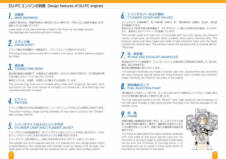
架 構FRAME9.
架構は鋼板と鋳鋼部品を溶接一体化、もしくはダクタイル鋳鉄一体型の強固な構造で、爆発力・運動部分の慣性力に対し十分な剛性を有しています。架構下部には鋼板製の油溜が装備されます。The frame is fabricated from plate material combined with cast steel or one piece ductile cast iron. Its structure is strong enough to withstand combustion forces and the stresses of moving parts. It is equipped with an oil sump of steel plate which is mounted on the bottom of the frame.
クランク軸CRANKSHAFT2.
クランク軸は合金鋼製の一体鍛造形で、バランスウェイトが取付けられます。The forged alloy steel crankshaft is made in one piece, to which balance weights are fitted.
接合棒CONNECTING RODS3.
接合棒は鍛造合金鋼製で、大端部は2分割斜割り、または3分割水平割です。2分割型接合棒の合せ面にはセレーション加工をしています。軸受けメタルは、大端部、小端部とも3層メタルを使用しています。The connecting rods are of forged alloy steel with diagonal two-part, with serrations on the inner faces or straight cut three-part. End bearings are manufactured from tri-metal.
ピストンPISTONS4.
ピストンは環状の大きな冷却油室をもち、シェーカクーリング方式により効果的に冷却されます。The piston having a large cooling chamber of loop type is coold by the “Shaker” type cooling method.
シリンダライナおよびシリンダ外衣CYLINDER LINER AND CYLINDER JACKET5.
シリンダライナは特殊鋳鉄製で、各シリンダごとに独立したシリンダ外衣におさめられ、これらはシリンダカバーと共に8本の支柱ボルトにより架構に結合されます。シリンダライナ上部は厚肉とし、内部に冷却水用の孔をもつボアクール形としています。The cylinder liner is of a special cast iron. It is inserted into the cylinder jacket, which is assembled to the crankcase with cylinder cover by means of 8 tie rods. The upper parts of the cylinder liner are cooled by the so called “bore cooling system”.

6 7
HAMシステムは、排ガス中の窒素酸化物(NOx)をさらに低減し、エンジン性能を改善する新しい技術です。HAM system is a new technology and very effective for further reduction of NOx emission in the exhaust gas by the improvement of the engine performance.
レイアウト例Layout1.
原 理Principle
過給機からの高温高圧の過給空気をHAMベッセルに通し、相対湿度を98%に上げます。水分を多く含んだ空気は通常の空気に比べ比熱が高くなるためエンジンで燃焼するときの燃焼が緩慢になりピーク温度が下がります。窒素酸化物の発生量は燃焼温度に比例するため、窒素酸化物の発生を低減させる効果を発揮します。HAMベッセルでの加湿時は蒸発水分が空気から蒸発潜熱を奪い空気温度を低下させるため、空気冷却器を省略することができます。The compressed air at high temperature and high pressure is passed from the turbocharger through HAM vessel, and the relative humidity is raised to 98%. Humidified charge air effects lower temperature in the combustion chamber. It can reduce volume of NOx because the amount of oxide of nitrogen is in proportion to the combustion temperature. HAM system can omit an air cooler because the evaporative water takes the evaporative latent heat from the air and decreases air temperature.
2.
加湿タンク(HAMベッセル)の構造Structure of Humidification tower (HAM vessel)
エンジンに送る空気に水を噴霧することにより加湿する装置です。蒸発水分で加湿を行うため、加湿用水として海水が使用できます。HAM vessel humidifies charge air from the turbocharger by spraying water. Seawater can be used because it humidifies with the evaporative water.
3.
窒素酸化物低減効果(理論値)NOx Reduction Effect (Theoretical value)
低減効果はエンジンに送られる空気に添加された水分量により決まり、理論的には下記カーブとなります。添加する水分量はHAMベッセル出口の空気の絶対湿度を変化させることで行います。ここに記載の低減率はその時点で排出している量からの数字であり、エンジンのチューニング変更を併せて行った場合などは、ここで示した低減率とは異なります。The effect of the decrease decides by the volume of water in the air to the engine, and it is indicated as a curve in the graph below theoretically. The added volume of water is done by change of the absolute humidity after HAM vessel. The decrease rate described here is a value from the amount that has been exhausted at that time, and it is different in case of the engine tuning change.
4.
HAMシステムの“HAM”とはHumid Air Motor(吸気加湿装置)の頭文字をとったもので、MAN Diesel SAS 社(旧 S.E.M.T. Pielstick社)の技術です。HAM is the technology of MAN Diesel SAS and stands for Humid Air Motor.
過給機から出て来た空気Compressedcharge air fomthe turbocharger
海水入口Seawater
海水を噴霧Spraying seawater
加湿タンクHAM vessel
エンジンへ送る加湿された空気Humidifiedcharge airto the engine
0
10
20
30
40
50
60
70
80
90
100
100
90
80
70
60
50
40
30
20
10
0
NOXと水分の影響NOx-Humidity Trend
NOX低減
NOx reduction
NOX排出量
Relative NOx emission
0 10 20 30 40 50 60 70 80 90 100 110 120空気中に投入した水分量X H2O
g/kg
エンジンEngine
過給機Turbocharger
加湿タンクHAM vessel
発電機Generator
排気ガス流れExhaust gas
吸込み空気Intake air 加湿タンク
HAM vessel
過給機Turbocharger
空気の流れCompressed air
エンジンengine
% %
HAMシステム HAM system
HAM vessel

8 9
1982年の販売以来、豊富な実績と根強い人気を持ち、フェリーや貨物船の主機や陸上発電設備など幅広いニーズに応えるモデルです。After release of PC2-6 types in 1982, these are very popular and a lot of engines have been delivered .PC2-6 types are suitable for the main engine of ferry boats, cargos and for generator units.
Engine type
Cylinder arrangement Number of cylinder
Cyl. Bore x Stroke
4 stroke, signal acting, air-less injection, direct reversibletrunk piston type with turbocharger and air cooler
400 × 460
5202.227.97
5022.077.70
5002.287.67
5142.227.88
Engine Output
Engine speedB.M.E.P.
Piston speed
Engine outputGenerator outputEngine speedB.M.E.P.
Piston speedEngine outputGenerator outputEngine speedB.M.E.P.
Piston speed
Output
Engine speedB.M.E.P.
Piston speed
Main Engine for Marine
for Generating Set
M.C.R.
N.O.R.
50 Hertz
60 Hertz
mmkW(PS)rpmMPam/skW(PS)rpmMPam/skWkWrpmMPam/skWkWrpmMPam/s
3,300 3,850 4,400 4,950 6,600 7,700 8,800 9,900 (4,500) (5,250) (6,000) (6,750) (9,000) (10,500) (12,000) (13,500)
2,970 3,465 3,960 4,455 5,940 6,930 7,920 8,910 (4,050) (4,725) (5,400) (6,075) (8,100) (9,450) (10,800) (12,150)
3,300 3,850 4,400 4,950 6,600 7,700 8,800 9,900 3,200 3,730 4,270 4,800 6,400 7,470 8,540 9,600
3,300 3,850 4,400 4,950 6,600 7,700 8,800 9,900 3,200 3,730 4,270 4,800 6,400 7,470 8,540 9,600
L V 6 7 8 9 12 14 16 18
Starting system
Cooling system Cylinder jacket : Fresh water Piston : Lub. OilFuel valve : Fresh water Air cooler : Raw water or Sea water
Lubricating oil pumpH.T. cooling water pumpEngine driven pump (Option)
Fuel oil
Compressed air
Diesel oil or Heavy fuel oil
Remarks1. The rating to be based on : Ambient temp. 45°C, Atemspheric press. 0.1MPa (760 mmHg), Cooling sea water
temp. 32°C, Exhaust back pressure 250 mm Aq.2. The generator output to be calculated as 97% of the generator efficiency.3. The output of the above-mentioned might be restricted according to the operating output and the running hours
per year and so on. Please contact our Sales Department or Technical Department.
注)1. 上記の出力は周囲温度45℃、大気圧0.1MPa(760mmHg)、冷却海水温度32℃、排ガス背圧250mmAqの場合を示します。
2. 発電機出力は発電機効率を97%として計算しています。3. プラントの運転負荷、時間等の諸条件によっては最大出力を制限せざるを得ない場合があります。弊社営業部又は技術部にお問い合わせください。
PC2-6 PC2-6Bフェリー用主機や陸上発電設備など、2004 年に発売された新しいモデルです。PC2-6B types are newly released engines in 2004 for the main engine of ferry boats and for generator units.
Engine type
Cylinder arrangementNumber of cylinder
4 stroke, signal acting, air-less injection, trunk piston typewith turbocharger and air cooler
400 × 500
6002.3910
5792.239.65
6002.0110
V
Starting system
Cooling system Cylinder jacket : Fresh water Piston : Lub. OilAir cooler : Raw water or Sea water
Lubricating oil pumpH.T. cooling water pumpEngine driven pump (Option)
Fuel oil
Compressed air
Diesel oil and / or Heavy fuel oil
Engine output
Engine speedB.M.E.P.Piston speed
Engine output
Engine speedB.M.E.P.Piston speedEngine outputGenerator outputEngine speedB.M.E.P.Piston speed
Main Engine for Marine
for Generating Set
mmkW(PS)rpmMPam/skW(PS)rpmMPam/skWkWrpmMPam/s
12 14 16 18 20
9,000 10,500 12,000 13,500 15,000 (12,000) (14,000) (16,000) (18,000) (20,000)
8,100 9,450 10,800 12,150 13,500 (10,800) (12,600) (14,400) (16,200) (18,000)
8,100 9,450 10,800 12,150 13,500 7,935 9,260 10,580 11,905 13,230
Cyl. Bore x Stroke
M.C.R.
N.O.R.
50 and 60 Hertz
Remarks1. The rating to be based on : Ambient temp. 45°C, Atemspheric press. 0.1MPa (760 mmHg), Cooling sea
water temp. 32°C, Exhaust back pressure 250 mm Aq.2. The generator output is calculated as 98% of the generator efficiency.3. The output of the above-mentioned might be restricted according to the operating output and the running
hours per year and so on. Please contact our Sales Department or Technical Department.
注)1. 上記の出力は周囲温度 45℃、大気圧 0.1MPa(760mmHg)、冷却海水温度 32℃、排ガス背圧 250mmAqの場合を示します。
2. 発電機出力は発電機効率を98%として計算しました。3. プラントの運転負荷、時間等の諸条件によっては最大出力を制限せざるを得ない場合があります。弊社営業部又は技術部にお問い合わせください。

V型
L型
10 11
PC4-2B1993年に発売され、大型フェリーやRO/RO船用主機、陸上発電設備などに採用されるモデルです。PC4-2B types have been released in 1993 and are suitable for the large ferry boats, RO/R0 ships and generator units.
Engine type
Cylinder arrangementNumber of cylinder
4 stroke, signal acting, air-less injection, trunk piston typewith turbocharger and air cooler
570 × 660
4282.209.4
4132.069.1
4002.008.8
4281.989.4
V
Starting system
Cooling system Cylinder jacket : Fresh water Piston : Lub. OilFuel valve : Fresh water Air cooler : Raw water or Sea water
Lubricating oil pumpEngine driven pump (Option)Fuel oil
Compressed air
Diesel oil or Heavy fuel oil
Engine output
Engine speedB.M.E.P.Piston speed
Engine output
Engine speedB.M.E.P.Piston speedEngine outputGenerator outputEngine speedB.M.E.P.Piston speedEngine outputGenerator outputEngine speedB.M.E.P.Piston speed
Main Engine for Marine
for Generating Set
mmkW(PS)rpmMPam/skW(PS)rpmMPam/skWkWrpmMPam/skWkWrpmMPam/s
12 14 16 18 20
15,900 18,550 21,200 23,850 26,500 (21,600) (25,200) (28,800) (32,400) (36,000)
14,310 16,695 19,080 21,465 23,850 (19,440) (22,680) (25,920) (29,160) (32,400)
14,310 16,695 19,080 21,465 23,850 13,880 16,190 18,505 20,820 23,130
13,500 15,750 18,000 20,250 22,500 13,095 15,275 17,460 19,640 21,825
Cyl. Bore x Stroke
M.C.R.
N.O.R.
50 Hertz
60 Hertz
Remarks1. The rating to be based on : Ambient temp. 45°C, Atemspheric press. 0.1MPa (760 mmHg), Cooling sea water
temp. 32°C, Exhaust back pressure 250 mm Aq.2. The generator output is calculated as 97% of the generator efficiency.3. The output of the above-mentioned might be restricted according to the operating output and the running
hours per year and so on. Please contact our Sales Department or Technical Department.
注)1. 上記の出力は周囲温度 45℃、大気圧 0.1MPa(760mmHg)、冷却海水温度 32℃、排ガス背圧250mmAqの場合を示します。
2. 発電機出力は発電機効率を97%として計算しました。3. プラントの運転負荷、時間等の諸条件によっては最大出力を制限せざるを得ない場合があります。弊社営業部又は技術部にお問い合わせください。
寸法・重量 Dimensions and Weight
6PC2-6L7PC2-6L8PC2-6L9PC2-6L12PC2-6V14PC2-6V16PC2-6V18PC2-6V*2)
DIMENSION (mm) WEIGHT(ton) A B C D E F G
6,145 1,351 1,646 1,067.5 2,542 1,800 921.5 43 6,885 1,351 1,646 1,067.5 2,542 1,800 921.5 48 7,625 1,547 1,842 1,067.5 2,618 1,876 921.5 54 8,365 1,547 1,842 1,067.5 2,618 1,876 921.5 64 5,405 1,840 2,135 1,067.5 2,780 3,322 979 68 6,145 1,840 2,135 1,067.5 2,780 3,322 979 76 6,885 2,080 2,320 1,067.5 3,095 3,966 979 85 7,625 2,080 2,320 1,067.5 3,095 3,966 979 95 *3)
12PC2-6B14PC2-6B16PC2-6B18PC2-6B*1)20PC2-6B*2)
DIMENSION (mm) WEIGHT(ton) A B C D E F G
5,960 2,310 2,370 1,280 3,310 4,574 400 100 6,700 2,310 2,370 1,280 3,310 4,574 400 110 7,440 2,310 2,370 1,280 3,310 4,574 400 120 8,180 ̶ ̶ 1,280 ̶ ̶ 400 130 8,920 ̶ ̶ 1,280 ̶ ̶ 400 143 *3)
注)1.過給機・空気冷却器は、ご要望の性能によって 別置きになる可能性があります。2.過給機・空気冷却器ユニットは別置きになります。3.過給機・空気冷却器ユニットを含む重量です。
Remarks1. Turbocharger and Air cooler might be separately installed according to requirement engine performance.2. Turbocharger and Air cooler unit are separately installed.3. This value is including Turbocharger and Air cooler unit
12PC4-2B14PC4-2B16PC4-2B18PC4-2B20PC4-2B*2)
DIMENSION (mm) WEIGHT(ton) A B C D E F G
8,138 2,340 2,340 1,615 4,110 5,642 590 258 9,118 2,340 2,340 1,615 4,110 5,642 590 295 10,098 2,340 2,340 1,615 4,110 5,642 590 325 11,078 2,340 2,340 1,615 4,110 5,642 590 355 12,058 ̶ ̶ 1,615 ̶ 5,642 590 390 *3)

1004-5000(Fxcw) Printed in Japan
http://www.ihi.co.jp/du/ E-mail [email protected]
●本社 (Head Office)〒101-0041 東京都千代田区神田須田町2-8(プライム神田ビル)TEL:03-3257-8222 FAX:03-3257-8220Prime Kanda Building2-8 Kanda Suda-cho,Chiyoda-ku,Tokyo, 101-0041,JAPAN TEL:+81-3-3257-8222 FAX:+81-3-3257-8220
●相生事業所 (Aioi Works)〒 678-0041 兵庫県相生市相生 5292 番地 TEL:0791-24-2608 FAX:0791-24-26485292 Aioi,Aioi-shi,Hyogo-ken, 678-0041,JAPAN TEL:+81-791-24-2608 FAX:+81-791-24-2648
●神戸営業所 (Kobe Sales Office)〒 650-0022 兵庫県神戸市中央区元町通 1-1-1(新元町ビル) TEL:078-321-3881 FAX:078-391-2050Shin-Motomachi,Building1-1-1 Motomachi-dori,Chuou-ku,Kobe-shi,Hyogo-ken, 650-0022,JAPAN TEL:+81-78-321-3881 FAX:+81-78-391-2050