Embed Size (px)
Citation preview
Liquid Handling · Easy Handling!
Dispensette® SDispensette® S Organic
F I R S T C L A S S · B R A N D
您可在www.brand.de/cn/manuals 下载本产品的中文操作手册。
Gebrauchsanleitung3
Operating Manual31
Mode d'emploi59
Instrucciones de manejo87
Istruzioni per l'uso115
Eng
lish
Table of Contents
33
Page
Safety Instructions 34
Functions and Limitations of Use 35
Dispenser Selection Chart 38
Operating Elements 39
First Steps 40
Assembly 40
Priming 42
Dispensing 43
Accessories 44
Error Limits (Nominal Volume, Partial Volume) 46
Checking the Volume (Calibration) 47
Adjustment 48
Cleaning 49
Replacement of discharge tube/ valves 51
Autoclaving 53
Ordering Information · Accessories · Spare Parts 54
Troubleshooting 59
Repairs · Contact addresses 60
Calibration Service 61
Warranty Information · Disposal 62
34
This instrument may sometimes be used with hazardous materials, operations, and equipment. It is beyond the scope of this manual to address all of the potential safety risks associated with its use in such applica-tions. It is the responsibility of the user of this instrument to consult and establish appropriate safety and health practices and determine the applicability of regulatory limitations prior to use.
Safety Instructions
With the Dispensette® S and Dispensette® S Organic bottle-top dispensers, liquids can be dispensed directly from the supply bottle. Available in digital, analog and fixed models.The instruments are, according to the requirements of the DIN EN ISO 8655-5, marked DE-M and option-ally equipped with recirculation valve.
Please read the following carefully!
Functions and Limitations of Use
!
1. Every user must read and understand thisoperating manual before operation.
2. Follow general instructions for hazard preven-tion and safety instructions; e.g., wear protec-tive clothing, eye protection and gloves.
3. Observe all specifications provided by reagentmanufacturers.
4. When dispensing inflammable media, makesure to avoid the buildup of static charge, e.g.,do not dispense into plastic vessels; do notwipe instruments with a dry cloth.
5. Use the instrument only for dispensing liquids,with strict regard to the defined limitations ofuse and operating limitations. Observe operat-ing exclusions (see page 36)! If in doubt,contact the manufacturer or supplier.
6. Always use the instrument in such a way thatneither the user nor any other person isendangered. When dispensing, the dischargetube must always point away from you or anyother person. Avoid splashes. Only use suitablevessels.
7. Never press down the piston when the dis-charge tube closure is attached.
8. Never remove the discharge tube or the recir-culation valve while the dispensing cylinder isfilled.
9. Reagents can accumulate in the screw capof the discharge tube. Thus, the screw capshould be cleaned regularly.
10. For small bottles, and when using the flexibledischarge tube, use a bottle stand to preventtipping over.
11. Never carry the mounted instrument by thecylinder sleeve or the valve block. Breakageor loosening of the cylinder may also lead topersonal injury from chemicals (see page 41,Fig. 3).
12. Never use force on the instrument. Usesmooth gentle movements to operate thepiston upwards and downwards.
13. Use only original manufacturer's accessoriesand spare parts. Do not attempt to make anytechnical alterations. Do not dismantle theinstrument any further than is described in theoperating manual!
14. Always check the instrument for visible dam-age before use. If there is a sign of a potentialmalfunction (e.g., piston difficult to move,sticking valves or leakage), immediately stopdispensing. Consult the 'Troubleshooting' sec-tion of this manual (see page 59), and contactthe manufacturer if needed.
X
X
X
XX
X
X
X
X
Eng
lish
35
Functions and Limitations of Use
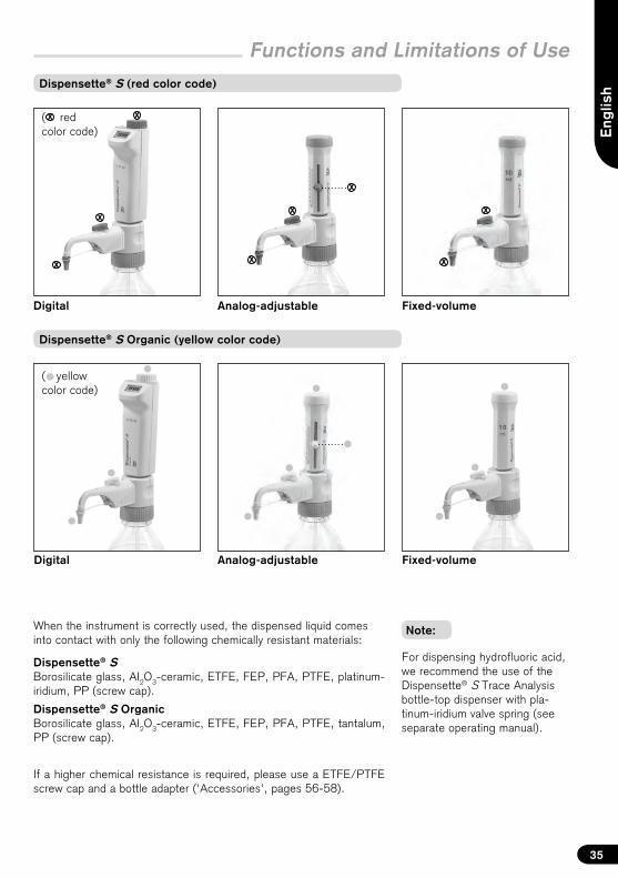
Digital Analog-adjustable
Dispensette® S Organic (yellow color code)
Digital Analog-adjustable Fixed-volume
Dispensette® S (red color code)
( yellow color code)
( red color code)
When the instrument is correctly used, the dispensed liquid comes into contact with only the following chemically resistant materials:
Dispensette® SBorosilicate glass, AI2O3-ceramic, ETFE, FEP, PFA, PTFE, platinum-iridium, PP (screw cap).
Dispensette® S OrganicBorosilicate glass, AI2O3-ceramic, ETFE, FEP, PFA, PTFE, tantalum, PP (screw cap).
If a higher chemical resistance is required, please use a ETFE/PTFE screw cap and a bottle adapter ('Accessories', pages 56-58).
Fixed-volume
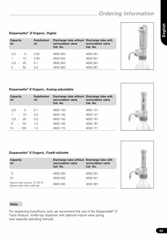
For dispensing hydrofluoric acid, we recommend the use of the Dispensette® S Trace Analysis bottle-top dispenser with pla-tinum-iridium valve spring (see separate operating manual).
Note:
36
Functions and Limitations of Use
This instrument is designed for dispensing liquids, observing the following physical limits:
– use temperature from +15 °C to +40 °C (from59 °F to 104 °F) of instrument and reagent
– vapor pressure up to max. 600 mbar. Aspirateslowly above 300 mbar, in order to prevent theliquid from boiling.
– kinematic viscosity up to 500 mm2/s(dynamic viscosity [mPas] =kinematic viscosity [mm²/s] x density [g/cm³])
– Density up to 2.2 g/cm3
Limitations of Use Operating Limitations
Liquids, which form deposits may make the piston difficult to move or may cause jamming (e.g., crystallizing solutions or concentrated alkaline solu-tions). If the piston movement becomes sluggish or stiff, the instrument should be cleaned immediately (page 49).
When dispensing inflammable media, make sure to avoid to buildup of static charge, e.g., do not dispense into plastic vessels; do not wipe instru-ments with a dry cloth.
Dispensette® S is designed for general labora-tory applications and complies with the relevant standards, e.g. DIN EN ISO 8655. Compatibility of the instrument for a specific application (e.g., trace material analysis, food sector etc.) must be checked by the user. Approvals for specific applications, e.g. for production and administration of food, pharma-ceuticals or cosmetics are not available.
Dispensette® S never use with:
– liquids attacking Al2O3-ceramic, ETFE, FEP, PFAand PTFE (e.g., dissolved sodium azide*)
– liquids attacking borosilicate glass (e.g.,hydrofluoric acid)
– liquids which are decomposed catalyticallyby platinum-iridium (e.g., H2O2)
– hydrochloric acid > 20 % and nitric acid > 30 %
– tetrahydrofuran
– trifluoroacetic acid
– explosive liquids (e.g., carbon disulfide)
– suspensions (e.g., of charcoal) as solid particlesmay clog or damage the instrument
– liquids attacking PP (screw cap)**
Operating Exclusions
Dispensette® S Organic never use with:
– liquids attacking Al2O3-ceramic, tantalum, ETFE,FEP, PFA and PTFE (e.g., dissolved sodiumazide*)
– liquids attacking borosilicate glass (e.g.,hydrofluoric acid)
– bases and saline solutions
– explosive liquids (e.g., carbon disulfide)
– suspensions (e.g., of charcoal) as solid particlesmay clog or damage the instrument
– liquids attacking PP (screw cap)**
* Dissolved sodium azide permitted up to a concentration of max. 0.1%.
** When stronger chemical resistance is needed, use the ETFE/PTFE screw caps ('Accessories', page 58).
Eng
lish
37
Store the instrument and accessories only in cleaned condition in a cool and dry place. Storage temperature: from -20 °C to +50 °C (from -4 °F to 122 °F).
Storage Conditions
Dispensette® S: Its broad range of application permits bottle dispensing of aggressive reagents, including concentrated acids such as H3PO4, H2SO4, bases like NaOH, KOH, saline solutions, as well as many organic solvents.
Dispensette® S Organic is ideal for dispens-ing of organic solvents including chlorinated and fluorinated hydrocarbons (e.g., trichlorotrifluoro-ethane and dichloromethane), concentrated acids (e.g., HCl and HNO3), trifluoroacetic acid (TFA), tetrahydofuran (THF) and peroxides.
Recommended Application Range
For guidelines on selecting the right dispenser ob-serve the corresponding Operating Exclusions and the 'Dispenser selection chart' on the next page.
For dispensing hydrofluoric acid, we recommend the use of the Dispensette® S Trace Analysis bottle-top dispenser with platinum-iridium valve spring (see separate operating manual).
Note:
Functions and Limitations of Use
38
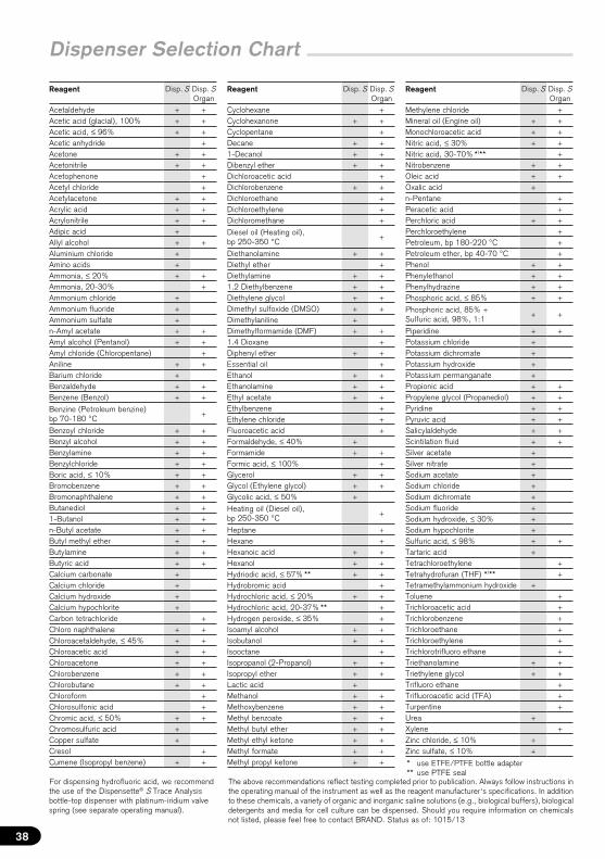
Dispenser Selection Chart
Reagent Disp. S Disp. S Organ
Acetaldehyde + +Acetic acid (glacial), 100% + +Acetic acid, ≤ 96% + +Acetic anhydride +Acetone + +Acetonitrile + +Acetophenone +Acetyl chloride +Acetylacetone + +Acrylic acid + +Acrylonitrile + +Adipic acid +Allyl alcohol + +Aluminium chloride +Amino acids +Ammonia, ≤ 20% + +Ammonia, 20-30% +Ammonium chloride +Ammonium fluoride +Ammonium sulfate +n-Amyl acetate + +Amyl alcohol (Pentanol) + +Amyl chloride (Chloropentane) +Aniline + +Barium chloride +Benzaldehyde + +Benzene (Benzol) + +
Benzine (Petroleum benzine) bp 70-180 °C
+
Benzoyl chloride + +Benzyl alcohol + +Benzylamine + +Benzylchloride + +Boric acid, ≤ 10% + +Bromobenzene + +Bromonaphthalene + +Butanediol + +1-Butanol + +n-Butyl acetate + +Butyl methyl ether + +Butylamine + +Butyric acid + +Calcium carbonate +Calcium chloride +Calcium hydroxide +Calcium hypochlorite +Carbon tetrachloride +Chloro naphthalene + +Chloroacetaldehyde, ≤ 45% + +Chloroacetic acid + +Chloroacetone + +Chlorobenzene + +Chlorobutane + +Chloroform +Chlorosulfonic acid +Chromic acid, ≤ 50% + +Chromosulfuric acid +Copper sulfate +Cresol +Cumene (Isopropyl benzene) + +
Reagent Disp. S Disp. S Organ
Cyclohexane +Cyclohexanone + +Cyclopentane +Decane + +1-Decanol + +Dibenzyl ether + +Dichloroacetic acid +Dichlorobenzene + +Dichloroethane +Dichloroethylene +Dichloromethane +
Diesel oil (Heating oil), bp 250-350 °C
+
Diethanolamine + +Diethyl ether +Diethylamine + +1.2 Diethylbenzene + +Diethylene glycol + +Dimethyl sulfoxide (DMSO) + +Dimethylaniline +Dimethylformamide (DMF) + +1.4 Dioxane +Diphenyl ether + +Essential oil +Ethanol + +Ethanolamine + +Ethyl acetate + +Ethylbenzene +Ethylene chloride +Fluoroacetic acid +Formaldehyde, ≤ 40% +Formamide + +Formic acid, ≤ 100% +Glycerol + +Glycol (Ethylene glycol) + +Glycolic acid, ≤ 50% +
Heating oil (Diesel oil), bp 250-350 °C
+
Heptane +Hexane +Hexanoic acid + +Hexanol + +Hydriodic acid, ≤ 57% ** + +Hydrobromic acid +Hydrochloric acid, ≤ 20% + +Hydrochloric acid, 20-37% ** +Hydrogen peroxide, ≤ 35% +Isoamyl alcohol + +Isobutanol + +Isooctane +Isopropanol (2-Propanol) + +Isopropyl ether + +Lactic acid +Methanol + +Methoxybenzene + +Methyl benzoate + +Methyl butyl ether + +Methyl ethyl ketone + +Methyl formate + +Methyl propyl ketone + +
Reagent Disp. S Disp. S Organ
Methylene chloride +Mineral oil (Engine oil) + +Monochloroacetic acid + +Nitric acid, ≤ 30% + +Nitric acid, 30-70% */** +Nitrobenzene + +Oleic acid + +Oxalic acid +n-Pentane +Peracetic acid +Perchloric acid + +Perchloroethylene +Petroleum, bp 180-220 °C +Petroleum ether, bp 40-70 °C +Phenol + +Phenylethanol + +Phenylhydrazine + +Phosphoric acid, ≤ 85% + +
Phosphoric acid, 85% + Sulfuric acid, 98%, 1:1
+ +
Piperidine + +Potassium chloride +Potassium dichromate +Potassium hydroxide +Potassium permanganate +Propionic acid + +Propylene glycol (Propanediol) + +Pyridine + +Pyruvic acid + +Salicylaldehyde + +Scintilation fluid + +Silver acetate +Silver nitrate +Sodium acetate +Sodium chloride +Sodium dichromate +Sodium fluoride +Sodium hydroxide, ≤ 30% +Sodium hypochlorite +Sulfuric acid, ≤ 98% + +Tartaric acid +Tetrachloroethylene +Tetrahydrofuran (THF) */** +Tetramethylammonium hydroxide +Toluene +Trichloroacetic acid +Trichlorobenzene +Trichloroethane +Trichloroethylene +Trichlorotrifluoro ethane +Triethanolamine + +Triethylene glycol + +Trifluoro ethane +Trifluoroacetic acid (TFA) +Turpentine +Urea +Xylene +Zinc chloride, ≤ 10% +Zinc sulfate, ≤ 10% +
* use ETFE/PTFE bottle adapter** use PTFE seal
For dispensing hydrofluoric acid, we recommend the use of the Dispensette® S Trace Analysis bottle-top dispenser with platinum-iridium valve spring (see separate operating manual).
The above recommendations reflect testing completed prior to publication. Always follow instructions in the operating manual of the instrument as well as the reagent manufacturer‘s specifications. In addition to these chemicals, a variety of organic and inorganic saline solutions (e.g., biological buffers), biological detergents and media for cell culture can be dispensed. Should you require information on chemicals not listed, please feel free to contact BRAND. Status as of: 1015/13
Eng
lish
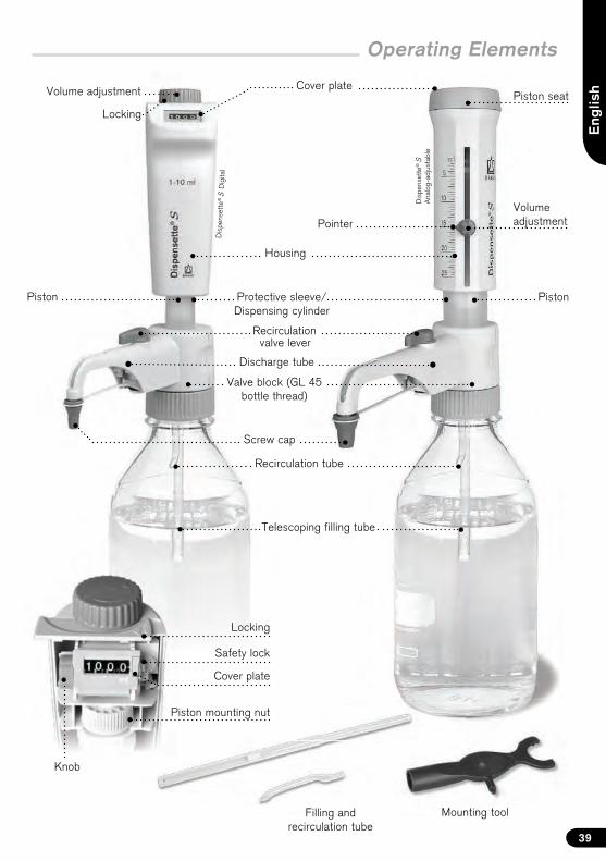
Operating Elements
Recirculation tube
Telescoping filling tube
Volume adjustment
Mounting toolFilling and recirculation tube
Locking
39
Cover plate
Volume adjustment
Housing
Screw cap
valve lever
Protective sleeve/ Dispensing cylinder
Piston Piston
Valve block (GL 45 bottle thread)
Discharge tube
Recirculation
Piston seat
Pointer
Knob
Safety lock
Cover plate
Piston mounting nut
Locking
Dis
pens
ette
® S
Dig
ital
Dis
pens
ette
® S
A
nalo
g-ad
just
able
1
2
40
First Steps
Is everything in the package?
Confirm that your package includes:Bottle-top dispenser Dispensette® S or Dispensette® S Organic, discharge tube or discharge tube with recirculation valve, telescoping filling tube, recirculation tube (included only in recirculation valve models), mounting tool, bottle adapters (listed below), a performance certificate and this operating manual.
Wear protective clothing, eye protection and gloves! Follow all safety instructions and observe limitations of use and operating limitations (page 34-36).
Warning:
Assembly
Nominal volume, ml Adapters for bottle thread
Filling tubeLength, mm
1, 2, 5, 10 GL 24-25, GL 28/S 28, GL 32-33, GL 38, S 40 125-240
25, 50, 100 GL 32-33, GL 38, S 40 170-330
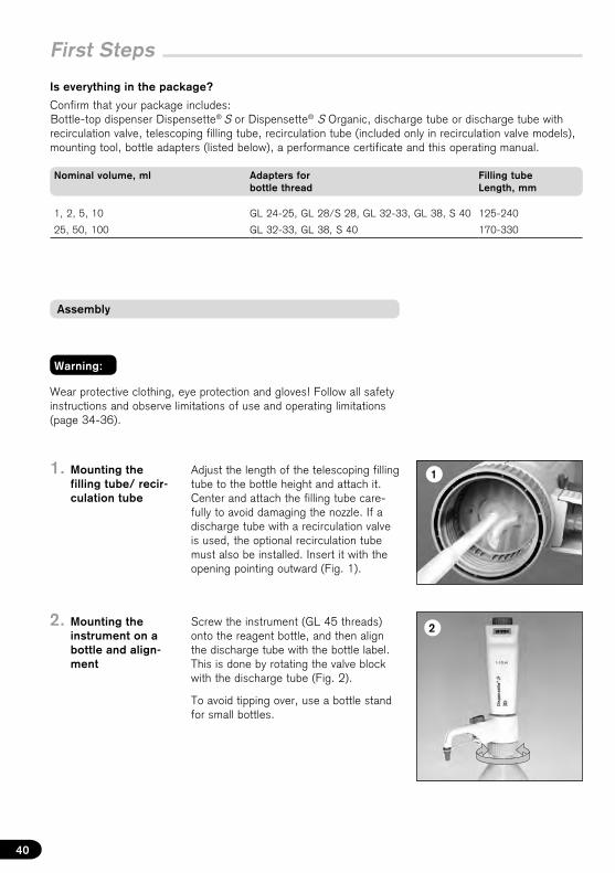
2. Mounting theinstrument on abottle and align-ment
Screw the instrument (GL 45 threads) onto the reagent bottle, and then align the discharge tube with the bottle label. This is done by rotating the valve block with the discharge tube (Fig. 2).
To avoid tipping over, use a bottle stand for small bottles.
1. Mounting thefilling tube/ recir-culation tube
Adjust the length of the telescoping filling tube to the bottle height and attach it. Center and attach the filling tube care-fully to avoid damaging the nozzle. If a discharge tube with a recirculation valve is used, the optional recirculation tube must also be installed. Insert it with the opening pointing outward (Fig. 1).
3
Eng
lish
41
First Steps
Note:
Warning:
For bottles with other thread sizes, select a suitable adapter.
The adapters supplied with the instrument are made of polypropylene (PP), and can only be used for media which do not attack PP.If a higher chemical resistance is required, please use a EFTE/PTFE bottle adapter ('Accessories', page 56).
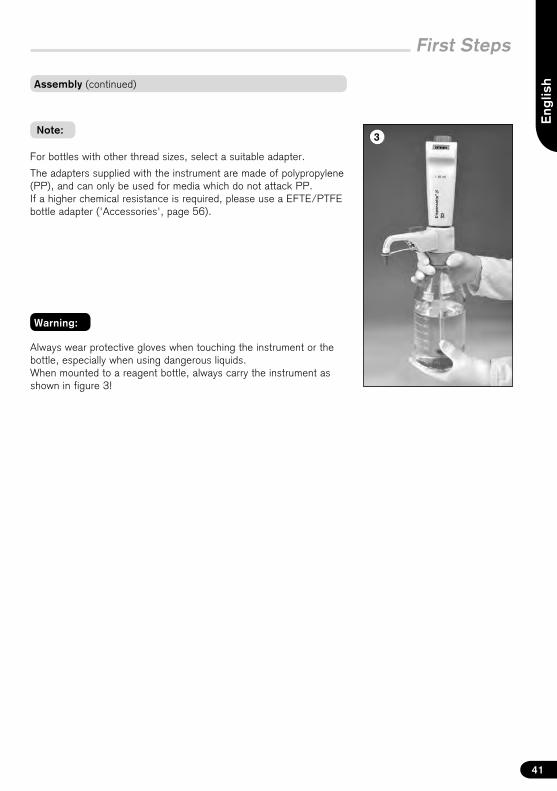
Always wear protective gloves when touching the instrument or the bottle, especially when using dangerous liquids.When mounted to a reagent bottle, always carry the instrument as shown in figure 3!
Assembly (continued)
2
3
4
5
30 mm
1
!
42
Priming
Note:
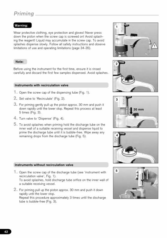
1. Open the screw cap of the discharge tube (see 'instrument withrecirculation valve', Fig. 1).To avoid splashes, hold discharge tube orifice on the inner wall ofa suitable receiving vessel.
2. For priming pull up the piston approx. 30 mm and push it downrapidly until the lower stop.Repeat this procedure approximately 3 times until the dischargetube is bubble-free (Fig. 3).
1. Open the screw cap of the dispensing tube (Fig. 1).
2. Set valve to 'Recirculate' (Fig. 2).
3. For priming gently pull up the piston approx. 30 mm and push itdown rapidly until the lower stop. Repeat this process at least5 times (Fig. 3).
4. Turn valve to 'Dispense' (Fig. 4).
5. To avoid splashes when priming hold the discharge tube on theinner wall of a suitable receiving vessel and dispense liquid toprime the discharge tube until it is bubble-free. Wipe away anyremaining drops from the discharge tube (Fig. 5).
Before using the instrument for the first time, ensure it is rinsed carefully and discard the first few samples dispensed. Avoid splashes.
Wear protective clothing, eye protection and gloves! Never press down the piston when the screw cap is screwed on! Avoid splash-ing the reagent! Liquid may accumulate in the screw cap. To avoid splashes dispense slowly. Follow all safety instructions and observe limitations of use and operating limitations (page 34-35).
Warning:
Instruments with recirculation valve
Instruments without recirculation valve
!
–+
1
2
3
21 3 Eng
lish
43
Dispensing
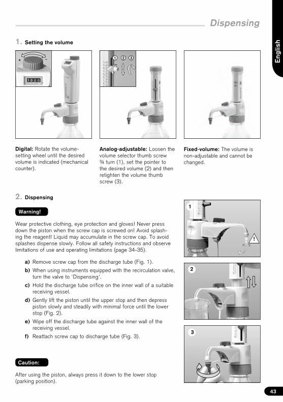
Digital: Rotate the volume-setting wheel until the desired volume is indicated (mechanical counter).
Fixed-volume: The volume is non-adjustable and cannot be changed.
1. Setting the volume
2. Dispensing
After using the piston, always press it down to the lower stop (parking position).
Caution:
Warning!
Analog-adjustable: Loosen the volume selector thumb screw ¾ turn (1), set the pointer to the desired volume (2) and then retighten the volume thumb screw (3).
a) Remove screw cap from the discharge tube (Fig. 1).
b) When using instruments equipped with the recirculation valve,turn the valve to 'Dispensing'.
c) Hold the discharge tube orifice on the inner wall of a suitablereceiving vessel.
d) Gently lift the piston until the upper stop and then depresspiston slowly and steadily with minimal force until the lowerstop (Fig. 2).
e) Wipe off the discharge tube against the inner wall of thereceiving vessel.
f) Reattach screw cap to discharge tube (Fig. 3).
Wear protective clothing, eye protection and gloves! Never press down the piston when the screw cap is screwed on! Avoid splash-ing the reagent! Liquid may accumulate in the screw cap. To avoid splashes dispense slowly. Follow all safety instructions and observe limitations of use and operating limitations (page 34-35).
2
3
1
4
44
Accessories
Warning:
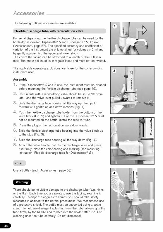
For serial dispensing the flexible discharge tube can be used for the bottle-top dispenser Dispensette® S and Dispensette® S Organic ('Accessories', page 57). The specified accuracy and coefficient of variation of the instrument are only obtained for volumes > 2 ml and by gently approaching the upper and lower stops. The coil of the tubing can be stretched to a length of the 800 mm max. The entire coil must lie in regular loops and must not be twisted.
The applicable operating exclusions are those for the corresponding instrument used.
Assembly
1. If the Dispensette® S was in use, the instrument must be cleanedbefore mounting the flexible discharge tube (see page 49).
2. Instruments with a recirculating valve should be set to 'Recircu-late', and the valve lever pulled upwards to remove it.
3. Slide the discharge tube housing all the way up, then pull itforward with gentle up and down motions (Fig. 1).
4. Push the flexible discharge tube holder from the bottom of thevalve block (Fig. 2) and tighten it. For this, Dispensette® S mustnot be mounted on the bottle. Install the receiver tube.
5. Press the plug of the recirculation valve downwards.
6. Slide the flexible discharge tube housing into the valve block upto the stop (Fig. 3).
7. Slide the discharge tube housing all the way down (Fig. 4).
8. Attach the valve handle that fits the discharge valve and pressit in firmly. Note the color coding and marking (see mountinginstruction 'Flexible discharge tube for Dispensette® S').
There should be no visible damage to the discharge tube (e.g. kinks or the like). Each time you are going to use the tubing, examine it carefully! To dispense aggressive liquids, you should take safety measures in addition to the normal precautions. We recommend use of a protective shield. The bottle must be supported using a bottle stand. To help avoid reagent splashing from the tube, always grip the tube firmly by the handle and replace into the holder after use. For cleaning rinse the tube carefully. Do not dismantle!
The following optional accessories are available:
Use a bottle stand ('Accessories', page 58).
Note:
Flexible discharge tube with recirculation valve
1
2
3
1
2
Eng
lish
45
Accessories
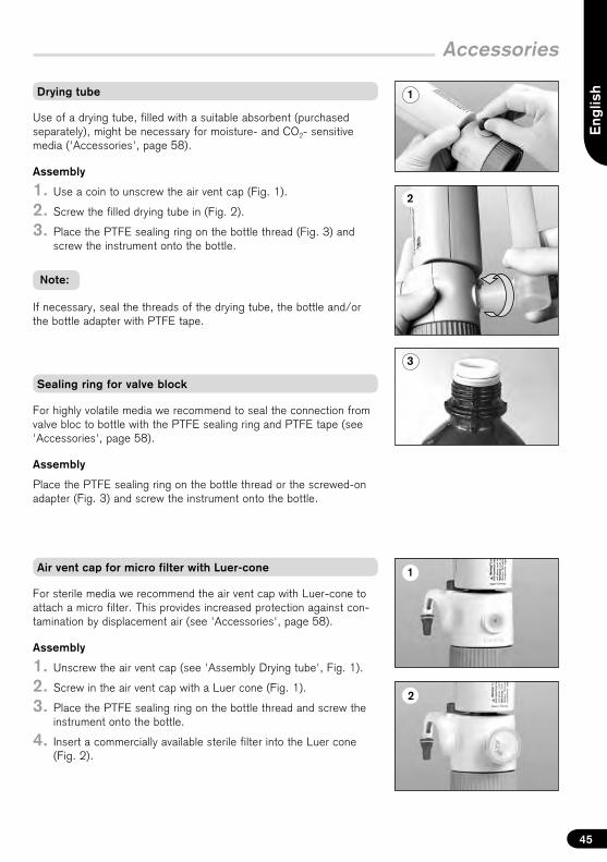
Use of a drying tube, filled with a suitable absorbent (purchased separately), might be necessary for moisture- and CO2- sensitive media ('Accessories', page 58).
Assembly
1. Use a coin to unscrew the air vent cap (Fig. 1).
2. Screw the filled drying tube in (Fig. 2).
3. Place the PTFE sealing ring on the bottle thread (Fig. 3) andscrew the instrument onto the bottle.
If necessary, seal the threads of the drying tube, the bottle and/or the bottle adapter with PTFE tape.
Note:
For sterile media we recommend the air vent cap with Luer-cone to attach a micro filter. This provides increased protection against con-tamination by displacement air (see 'Accessories', page 58).
Assembly
1. Unscrew the air vent cap (see 'Assembly Drying tube', Fig. 1).
2. Screw in the air vent cap with a Luer cone (Fig. 1).
3. Place the PTFE sealing ring on the bottle thread and screw theinstrument onto the bottle.
4. Insert a commercially available sterile filter into the Luer cone(Fig. 2).
For highly volatile media we recommend to seal the connection from valve bloc to bottle with the PTFE sealing ring and PTFE tape (see 'Accessories', page 58).
Assembly
Place the PTFE sealing ring on the bottle thread or the screwed-on adapter (Fig. 3) and screw the instrument onto the bottle.
Drying tube
Sealing ring for valve block
Air vent cap for micro filter with Luer-cone
!20 °C
ExType Digital • Easy Calibration is manufac-tured under U.S. Patent 5,957,330.
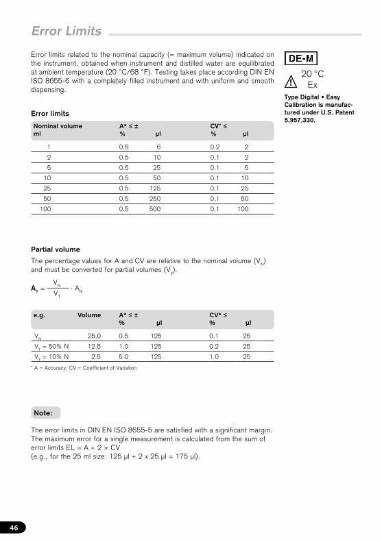
Error Limits
Error limits related to the nominal capacity (= maximum volume) indicated on the instrument, obtained when instrument and distilled water are equilibrated at ambient temperature (20 °C/68 °F). Testing takes place according DIN EN ISO 8655-6 with a completely filled instrument and with uniform and smooth dispensing.
46
Error limits
Nominal volume ml
A* ≤ ± % µl
CV* ≤ % µl
1 0.6 6 0.2 2
2 0.5 10 0.1 2
5 0.5 25 0.1 5
10 0.5 50 0.1 10
25 0.5 125 0.1 25
50 0.5 250 0.1 50
100 0.5 500 0.1 100
Partial volume
The percentage values for A and CV are relative to the nominal volume (VN) and must be converted for partial volumes (Vp).
The error limits in DIN EN ISO 8655-5 are satisfied with a significant margin. The maximum error for a single measurement is calculated from the sum of error limits EL = A + 2 × CV (e.g., for the 25 ml size: 125 µl + 2 x 25 µl = 175 µl).
VN
VT
AT = · AN
e.g. Volume A* ≤ ± % µl
CV* ≤ % µl
VN 25.0 0.5 125 0.1 25
VT = 50% N 12.5 1.0 125 0.2 25
VT = 10% N 2.5 5.0 125 1.0 25
* A = Accuracy, CV = Coefficient of Variation
Note:
Eng
lish
47
xi = results of weighingsn = number of weighings
Z = correction factor(e. g., 1.0029 µl/mg at 20 °C, 1013 hPa)
V0 = nominal volume
Mean volume
V – V0
V0
A% = · 100Σ (xi – x ) 2
n – 1s = Z ·
Mean value x =Σ xi
n Mean volume V = x · Z
Accuracy Standard deviation Coefficient of variation
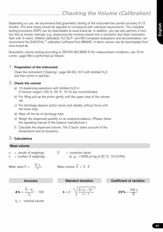
Checking the Volume (Calibration)
100 s
VCV% =
Gravimetric volume testing according to DIN EN ISO 8655-6 (for measurement conditions, see 'Error Limits', page 46) is performed as follows:
1. Preparation of the instrument
Clean the instrument ('Cleaning', page 49-52), fill it with distilled H2Oand then prime it carefully.
2. Check the volume
a) 10 dispensing operations with distilled H2O in3 Volume ranges (100 %, 50 %, 10 %) are recommended.
b) For filling pull up the piston gently until the upper stop of the volumeset.
c) For discharge depress piston slowly and steadily without force untilthe lower stop.
d) Wipe off the tip of discharge tube.
e) Weigh the dispensed quantity on an analytical balance. (Please followthe operating manual of the balance manufacturer.)
f) Calculate the dispensed volume. The Z factor takes account of thetemperature and air buoyancy.
3. Calculations
Depending on use, we recommend that gravimetric testing of the instrument be carried out every 3-12 months. This time frame should be adjusted to correspond with individual requirements. The complete testing procedure (SOP) can be downloaded at www.brand.de. In addition, you can also perform a func-tion test at shorter intervals, e.g. dispensing the nominal volume into a volumetric test flask (volumetric flask with 3 marks, DAkkS calibrated). For GLP- and ISO-compliant evaluations and documentation, we recommend the EASYCAL™ calibration software from BRAND. A demo version can be downloaded from www.brand.de.
21
3 4
2
3
1
4
5 6
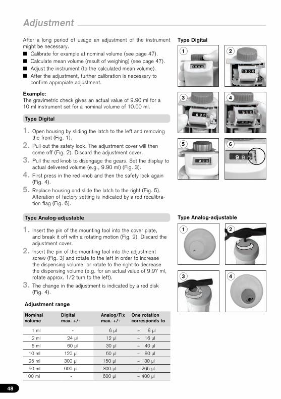
Adjustment
After a long period of usage an adjustment of the instrument might be necessary.� Calibrate for example at nominal volume (see page 47).� Calculate mean volume (result of weighing) (see page 47).� Adjust the instrument (to the calculated mean volume).� After the adjustment, further calibration is necessary to
confirm appropiate adjustment.
Example: The gravimetric check gives an actual value of 9.90 ml for a 10 ml instrument set for a nominal volume of 10.00 ml.
48
1. Open housing by sliding the latch to the left and removingthe front (Fig. 1).
2. Pull out the safety lock. The adjustment cover will thencome off (Fig. 2). Discard the adjustment cover.
3. Pull the red knob to disengage the gears. Set the display toactual delivered volume (e.g., 9.90 ml) (Fig. 3).
4. First press in the red knob and then the safety lock again(Fig. 4).
5. Replace housing and slide the latch to the right (Fig. 5).Alteration of factory setting is indicated by a red recalibra-tion flag (Fig. 6).
1. Insert the pin of the mounting tool into the cover plate,and break it off with a rotating motion (Fig. 2). Discard theadjustment cover.
2. Insert the pin of the mounting tool into the adjustmentscrew (Fig. 3) and rotate to the left in order to increasethe dispensing volume, or rotate to the right to decreasethe dispensing volume (e.g. for an actual value of 9.97 ml,rotate approx. 1/2 turn to the left).
3. The change in the adjustment is indicated by a red disk(Fig. 4).
Nominal volume
Digital max. +/-
Analog/Fix max. +/-
One rotation corresponds to
1 ml - 6 µl ~ 8 µl
2 ml 24 µl 12 µl ~ 16 µl
5 ml 60 µl 30 µl ~ 40 µl
10 ml 120 µl 60 µl ~ 80 µl
25 ml 300 µl 150 µl ~ 130 µl
50 ml 600 µl 300 µl ~ 265 µl
100 ml - 600 µl ~ 400 µl
Type Analog-adjustable
Type Digital
Adjustment range
Type Digital
Type Analog-adjustable
1
2a
Eng
lish
49
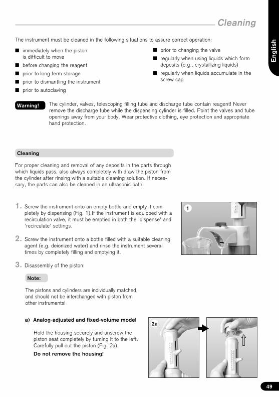
Cleaning
Cleaning
The cylinder, valves, telescoping filling tube and discharge tube contain reagent! Never remove the discharge tube while the dispensing cylinder is filled. Point the valves and tube openings away from your body. Wear protective clothing, eye protection and appropriate hand protection.
Warning!
� immediately when the pistonis difficult to move
� before changing the reagent
� prior to long term storage
� prior to dismantling the instrument
� prior to autoclaving
The instrument must be cleaned in the following situations to assure correct operation:
� prior to changing the valve
� regularly when using liquids which formdeposits (e.g., crystallizing liquids)
� regularly when liquids accumulate in thescrew cap
Note:
The pistons and cylinders are individually matched,and should not be interchanged with piston fromother instruments!
1. Screw the instrument onto an empty bottle and empty it com-pletely by dispensing (Fig. 1).If the instrument is equipped with arecirculation valve, it must be emptied in both the 'dispense' and'recirculate' settings.
2. Screw the instrument onto a bottle filled with a suitable cleaningagent (e.g. deionized water) and rinse the instrument severaltimes by completely filling and emptying it.
3. Disassembly of the piston:
For proper cleaning and removal of any deposits in the parts through which liquids pass, also always completely with draw the piston from the cylinder after rinsing with a suitable cleaning solution. If neces-sary, the parts can also be cleaned in an ultrasonic bath.
a) Analog-adjusted and fixed-volume model
Hold the housing securely and unscrew thepiston seat completely by turning it to the left.Carefully pull out the piston (Fig. 2a).
Do not remove the housing!
2b
3a 3b
Cleaning
Move the latch to the left and remove the front housing.
Right! Wrong!
50
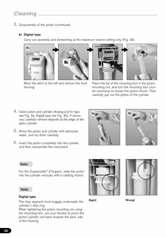
b) Digital type
3. Disassembly of the piston (continued).
Note:
Place the tip of the mounting tool in the piston mounting nut, and turn the mounting tool coun-ter-clockwise to loosen the piston mount. Then carefully pull out the piston of the cylinder.
4. Clean piston and cylinder (Analog and fix typesee Fig. 3a, Digital type see Fig. 3b). If neces-sary carefully remove deposits at the edge of theglass cylinder.
5. Rinse the piston and cylinder with deionizedwater, and dry them carefully.
6. Insert the piston completely into the cylinderand then reassemble the instrument.
Carry out assembly and dismantling at the maximum volume setting only (Fig. 2b).
Digital type
The stop segment must engage underneath the cylinder’s stop ring.When tightening the piston mounting nut using the mounting tool, use your thumbs to press the piston/cylinder unit back towards the back side of the housing.
For the Dispensette® S Organic, slide the piston into the cylinder vertically with a rotating motion.
Note:
3
2
1
2
1
Eng
lish
51
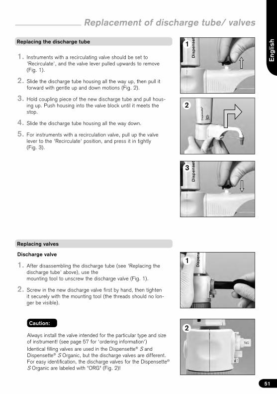
Replacement of discharge tube/ valves
Caution:
Always install the valve intended for the particular type and size of instrument! (see page 57 for 'ordering information')Identical filling valves are used in the Dispensette® S and Dispensette® S Organic, but the discharge valves are different. For easy identification, the discharge valves for the Dispensette® S Organic are labeled with "ORG" (Fig. 2)!
Replacing the discharge tube
1. Instruments with a recirculating valve should be set to'Recirculate', and the valve lever pulled upwards to remove(Fig. 1).
2. Slide the discharge tube housing all the way up, then pull itforward with gentle up and down motions (Fig. 2).
3. Hold coupling piece of the new discharge tube and pull hous-ing up. Push housing into the valve block until it meets thestop.
4. Slide the discharge tube housing all the way down.
5. For instruments with a recirculation valve, pull up the valvelever to the 'Recirculate' position, and press it in tightly(Fig. 3).
Replacing valves
Discharge valve
1. After disassembling the discharge tube (see 'Replacing thedischarge tube' above), use themounting tool to unscrew the discharge valve (Fig. 1).
2. Screw in the new discharge valve first by hand, then tightenit securely with the mounting tool (the threads should no lon- ger be visible).
1
2
52
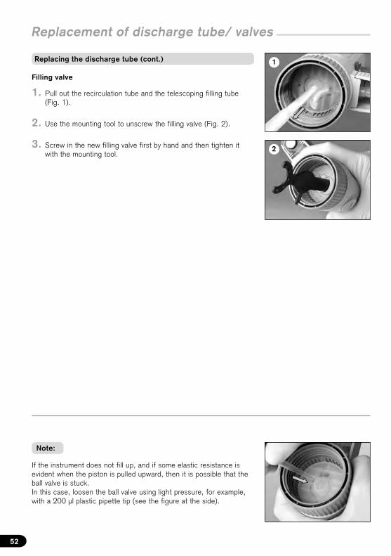
Note:
If the instrument does not fill up, and if some elastic resistance is evident when the piston is pulled upward, then it is possible that the ball valve is stuck.In this case, loosen the ball valve using light pressure, for example, with a 200 µl plastic pipette tip (see the figure at the side).
Filling valve
1. Pull out the recirculation tube and the telescoping filling tube(Fig. 1).
2. Use the mounting tool to unscrew the filling valve (Fig. 2).
3. Screw in the new filling valve first by hand and then tighten itwith the mounting tool.
Replacement of discharge tube/ valves
Replacing the discharge tube (cont.)
1a
1b
2
Eng
lish
53
Autoclaving
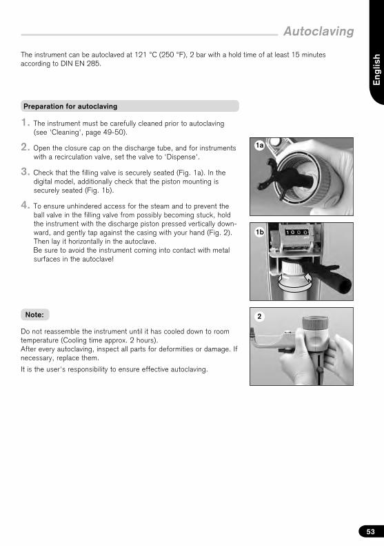
The instrument can be autoclaved at 121 °C (250 °F), 2 bar with a hold time of at least 15 minutes according to DIN EN 285.
Do not reassemble the instrument until it has cooled down to room temperature (Cooling time approx. 2 hours). After every autoclaving, inspect all parts for deformities or damage. If necessary, replace them.
It is the user's responsibility to ensure effective autoclaving.
Note:
1. The instrument must be carefully cleaned prior to autoclaving(see 'Cleaning', page 49-50).
2. Open the closure cap on the discharge tube, and for instrumentswith a recirculation valve, set the valve to 'Dispense'.
3. Check that the filling valve is securely seated (Fig. 1a). In thedigital model, additionally check that the piston mounting issecurely seated (Fig. 1b).
4. To ensure unhindered access for the steam and to prevent theball valve in the filling valve from possibly becoming stuck, holdthe instrument with the discharge piston pressed vertically down-ward, and gently tap against the casing with your hand (Fig. 2).Then lay it horizontally in the autoclave.Be sure to avoid the instrument coming into contact with metalsurfaces in the autoclave!
Preparation for autoclaving
54
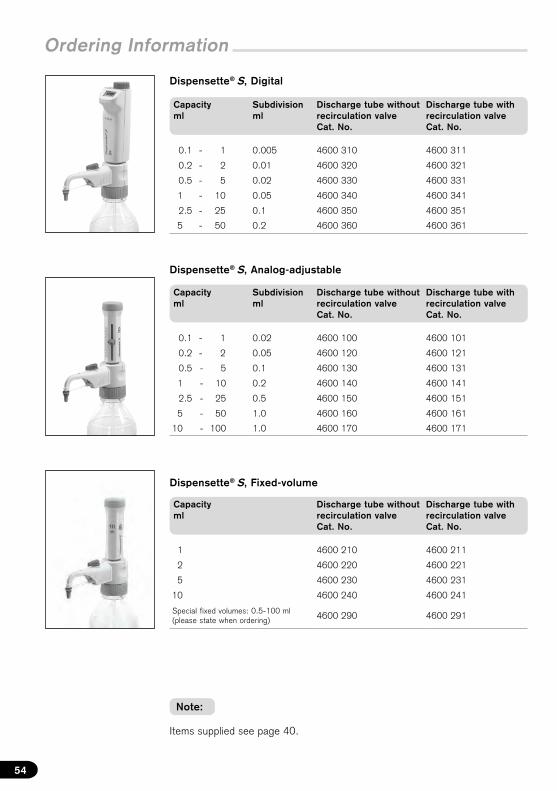
Ordering Information
Dispensette® S, Analog-adjustable
Dispensette® S, Fixed-volume
Items supplied see page 40.
Note:
Dispensette® S, Digital
Capacity ml
Subdivision ml
Discharge tube without recirculation valveCat. No.
Discharge tube with recirculation valveCat. No.
0.1 - 1 0.005 4600 310 4600 311
0.2 - 2 0.01 4600 320 4600 321
0.5 - 5 0.02 4600 330 4600 331
1 - 10 0.05 4600 340 4600 341
2.5 - 25 0.1 4600 350 4600 351
5 - 50 0.2 4600 360 4600 361
Capacity ml
Subdivision ml
Discharge tube without recirculation valveCat. No.
Discharge tube with recirculation valveCat. No.
0.1 - 1 0.02 4600 100 4600 101
0.2 - 2 0.05 4600 120 4600 121
0.5 - 5 0.1 4600 130 4600 131
1 - 10 0.2 4600 140 4600 141
2.5 - 25 0.5 4600 150 4600 151
5 - 50 1.0 4600 160 4600 161
10 - 100 1.0 4600 170 4600 171
Capacity ml
Discharge tube without recirculation valveCat. No.
Discharge tube with recirculation valveCat. No.
1 4600 210 4600 211
2 4600 220 4600 221
5 4600 230 4600 231
10 4600 240 4600 241
Special fixed volumes: 0.5-100 ml (please state when ordering) 4600 290 4600 291
Eng
lish
55
Ordering Information
For dispensing hydrofluoric acid, we recommend the use of the Dispensette® S Trace Analysis bottle-top dispenser with platinum-iridium valve spring (see separate operating manual).
Note:
Dispensette® S Organic, Digital
Capacity ml
Subdivision ml
Discharge tube without recirculation valveCat. No.
Discharge tube with recirculation valveCat. No.
0.5 - 5 0.02 4630 330 4630 331
1 - 10 0.05 4630 340 4630 341
2.5 - 25 0.1 4630 350 4630 351
5 - 50 0.2 4630 360 4630 361
Dispensette® S Organic, Analog-adjustable
Capacity ml
Subdivision ml
Discharge tube without recirculation valveCat. No.
Discharge tube with recirculation valveCat. No.
0.5 - 5 0.1 4630 130 4630 131
1 - 10 0.2 4630 140 4630 141
2.5 - 25 0.5 4630 150 4630 151
5 - 50 1.0 4630 160 4630 161
10 - 100 1.0 4630 170 4630 171
Dispensette® S Organic, Fixed-volume
Capacity ml
Discharge tube without recirculation valveCat. No.
Discharge tube with recirculation valveCat. No.
5 4630 230 4630 231
10 4630 240 4630 241
Special fixed volumes: 2-100 ml (please state when ordering) 4630 290 4630 291
56
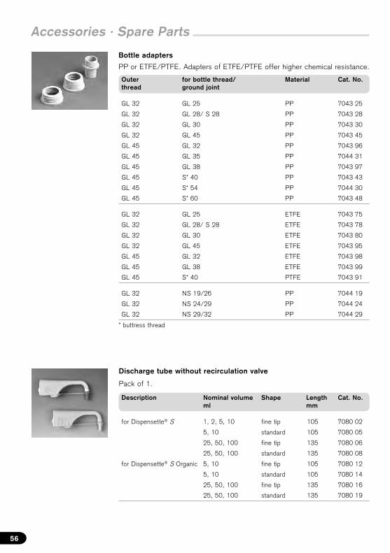
Bottle adapters
PP or ETFE/PTFE. Adapters of ETFE/PTFE offer higher chemical resistance.
Discharge tube without recirculation valve
Pack of 1.
Description Nominal volume ml
Shape Length mm
Cat. No.
for Dispensette® S 1, 2, 5, 10 fine tip 105 7080 02
5, 10 standard 105 7080 05
25, 50, 100 fine tip 135 7080 06
25, 50, 100 standard 135 7080 08
for Dispensette® S Organic 5, 10 fine tip 105 7080 12
5, 10 standard 105 7080 14
25, 50, 100 fine tip 135 7080 16
25, 50, 100 standard 135 7080 19
Accessories · Spare Parts
Outerthread
for bottle thread/ ground joint
Material Cat. No.
GL 32 GL 25 PP 7043 25
GL 32 GL 28/ S 28 PP 7043 28
GL 32 GL 30 PP 7043 30
GL 32 GL 45 PP 7043 45
GL 45 GL 32 PP 7043 96
GL 45 GL 35 PP 7044 31
GL 45 GL 38 PP 7043 97
GL 45 S* 40 PP 7043 43
GL 45 S* 54 PP 7044 30
GL 45 S* 60 PP 7043 48
GL 32 GL 25 ETFE 7043 75
GL 32 GL 28/ S 28 ETFE 7043 78
GL 32 GL 30 ETFE 7043 80
GL 32 GL 45 ETFE 7043 95
GL 45 GL 32 ETFE 7043 98
GL 45 GL 38 ETFE 7043 99
GL 45 S* 40 PTFE 7043 91
GL 32 NS 19/26 PP 7044 19
GL 32 NS 24/29 PP 7044 24
GL 32 NS 29/32 PP 7044 29
* buttress thread
Eng
lish
57
Accessories · Spare Parts
Nominal volume ml
Discharge tubeOuter Ø Inner Ømm mm
Cat. No.
1, 2, 5, 10 3 2 7081 32
25, 50, 100 4,5 3 7081 34
* not suitable for hydrofluoric acid
for nominal volume ml
Cat. No.
1, 2* 6749
5, 10 6727
25, 50, 100 6728
* with valve marking '1 + 2'
Discharge tube with recirculation valve
Pack of 1.
Description Nominal volume ml
Shape Length mm
Cat. No.
for Dispensette® S 1, 2, 5, 10 fine tip 105 7081 02
5, 10 standard 105 7081 04
25, 50, 100 fine tip 135 7081 06
25, 50, 100 standard 135 7081 09
for Dispensette® S Organic 5, 10 fine tip 105 7081 12
5, 10 standard 105 7081 14
25, 50, 100 fine tip 135 7081 16
25, 50, 100 standard 135 7081 19
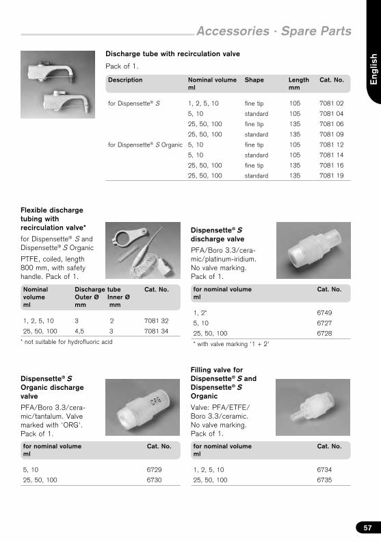
Flexible discharge tubing with recirculation valve*
for Dispensette® S and Dispensette® S Organic
PTFE, coiled, length 800 mm, with safety handle. Pack of 1.
Dispensette® S discharge valve
PFA/Boro 3.3/cera-mic/platinum-iridium.No valve marking.Pack of 1.
for nominal volume ml
Cat. No.
5, 10 6729
25, 50, 100 6730
Dispensette® S
Organic discharge valve
PFA/Boro 3.3/cera-mic/tantalum. Valve marked with 'ORG'.Pack of 1.
for nominal volume ml
Cat. No.
1, 2, 5, 10 6734
25, 50, 100 6735
Filling valve for Dispensette® S andDispensette® S Organic
Valve: PFA/ETFE/ Boro 3.3/ceramic.No valve marking.Pack of 1.
58
Accessories · Spare Parts
* ETFE/PTFE, if higher chemical resistance is requested
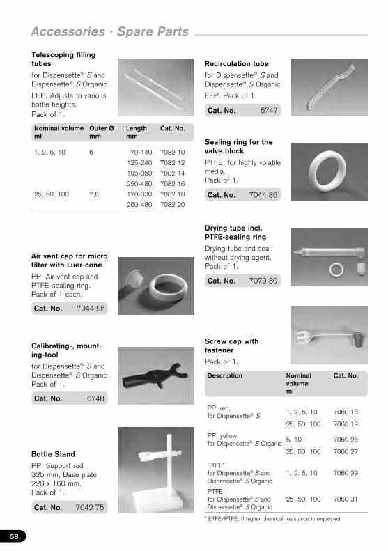
Calibrating-, mount-ing-tool
for Dispensette® S and Dispensette® S Organic Pack of 1.
Cat. No. 6748
Drying tube incl. PTFE-sealing ring
Drying tube and seal, without drying agent. Pack of 1.
Cat. No. 7079 30
Air vent cap for micro filter with Luer-cone
PP. Air vent cap and PTFE-sealing ring. Pack of 1 each.
Cat. No. 7044 95
Recirculation tube
for Dispensette® S and Dispensette® S Organic
FEP. Pack of 1.
Cat. No. 6747
Screw cap with fastener
Pack of 1.
Description Nominal volume ml
Cat. No.
PP, red, for Dispensette® S
1, 2, 5, 10 7060 18
25, 50, 100 7060 19
PP, yellow, for Dispensette® S Organic
5, 10 7060 25
25, 50, 100 7060 27
ETFE*, for Dispensette® S and Dispensette® S Organic
1, 2, 5, 10 7060 29
PTFE*, for Dispensette® S and Dispensette® S Organic
25, 50, 100 7060 31
Bottle Stand
PP. Support rod 325 mm, Base plate 220 x 160 mm. Pack of 1.
Cat. No. 7042 75
Cat. No. 7044 86
Sealing ring for the valve block
PTFE, for highly volatile media. Pack of 1.
Telescoping filling tubes
for Dispensette® S and Dispensette® S Organic
FEP. Adjusts to various bottle heights. Pack of 1.
Nominal volume ml
Outer Ø mm
Length mm
Cat. No.
1, 2, 5, 10 6 70-140 7082 10
125-240 7082 12
195-350 7082 14
250-480 7082 16
25, 50, 100 7,6 170-330 7082 18
250-480 7082 20
Eng
lish
59
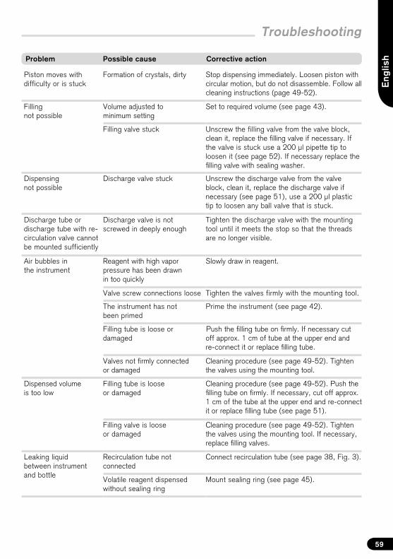
Problem Possible cause Corrective action
Troubleshooting
Piston moves with difficulty or is stuck
Formation of crystals, dirty Stop dispensing immediately. Loosen piston with circular motion, but do not disassemble. Follow all cleaning instructions (page 49-52).
Filling not possible
Volume adjusted to minimum setting
Set to required volume (see page 43).
Filling valve stuck Unscrew the filling valve from the valve block, clean it, replace the filling valve if necessary. If the valve is stuck use a 200 µl pipette tip to loosen it (see page 52). If necessary replace the filling valve with sealing washer.
Dispensing not possible
Discharge valve stuck Unscrew the discharge valve from the valve block, clean it, replace the discharge valve if necessary (see page 51), use a 200 µl plastic tip to loosen any ball valve that is stuck.
Discharge tube or discharge tube with re-circulation valve cannot be mounted sufficiently
Discharge valve is not screwed in deeply enough
Tighten the discharge valve with the mounting tool until it meets the stop so that the threads are no longer visible.
Air bubbles in the instrument
Reagent with high vapor pressure has been drawn in too quickly
Slowly draw in reagent.
Valve screw connections loose Tighten the valves firmly with the mounting tool.
The instrument has not been primed
Prime the instrument (see page 42).
Filling tube is loose or damaged
Push the filling tube on firmly. If necessary cut off approx. 1 cm of tube at the upper end and re-connect it or replace filling tube.
Valves not firmly connected or damaged
Cleaning procedure (see page 49-52). Tighten the valves using the mounting tool.
Dispensed volume is too low
Filling tube is loose or damaged
Cleaning procedure (see page 49-52). Push the filling tube on firmly. If necessary, cut off approx. 1 cm of the tube at the upper end and re-connect it or replace filling tube (see page 51).
Filling valve is looseor damaged
Cleaning procedure (see page 49-52). Tighten the valves using the mounting tool. If necessary, replace filling valves.
Leaking liquid between instrument and bottle
Recirculation tube not connected
Connect recirculation tube (see page 38, Fig. 3).
Volatile reagent dispensed without sealing ring
Mount sealing ring (see page 45).
60
Repairs · contact addresses
– Clean and decontaminate the instrument carefully.
– It is essential always to include an exact description of the type of malfunc-tion and the media used. If information regarding media used is missing,the instrument cannot be repaired.
– Shipment is at the risk and the cost of the sender.
In the U.S. and Canada:
– Contact BrandTech Scientific, Inc. and obtain authorization for the returnbefore sending your instrument for service.
– Return only cleaned and decontaminated instruments, with the ReturnAuthorization Number prominently displayed on the outside of the packageto the address provided with the Return Authorization Number.
Return for repair
Caution! Transporting of hazardous materials without a permit is a violation of federal law.
Outside the U.S. and Canada:
– Complete the “Declaration on Absence of Health Hazards” and send the instru-ment to the manufacturer or supplier. Ask your supplier or manufacturer for theform. The form can also be downloaded from www.brand.de.
Eng
lishISO 9001 and GLP-guidelines require regular examinations of your volumetric
instruments. We recommend checking the volume every 3-12 months. The interval depends on the specific requirements on the instrument. For instru-ments frequently used or in use with aggressive media, the interval should be shorter. The detailed testing instruction can be downloaded on www.brand.de or www.brandtech.com. BRAND also offers you the possibility to have your instruments calibrated by the BRAND Calibration Service or the BRAND-owned DAkkS Calibration Service. Just send in the instruments to be calibrated, accompanied by an indication of which kind of calibration you wish. Your instruments will be returned within a few days together with a test report (BRAND Calibration Service) or with a DAkkS Calibration Certificate. For further information, please contact your dealer or BRAND. Complete ordering information is available for download at www.brand.de (see Technical Documentation).
Calibration Service
61
Subject to technical modification without notice. Errors excepted.
Disposal
For the disposal of instruments, please observe the relevant national disposal regulations.
We shall not be liable for the consequences of improper handling, use, servic-ing, operation or unauthorized repairs of the instrument or the consequences of normal wear and tear especially of wearing parts such as pistons, seals, valves and the breakage of glass as well as the failure to follow the instructions of the operating manual. We are not liable for damage resulting from any actions not described in the operating manual or if non-original spare parts or components have been used.
U.S. and Canada:Information for warranty please see www.brandtech.com.
Warranty
62

9974 90 · Printed in Germany · 5/1015/3