Embed Size (px)
Citation preview

GRUNDFOS INSTRUCTIONS
DME, Variant AR (60-940 l/h)Installation and operating instructions


Ta
ble
of
co
nte
nts
3
DME, Variant AR (60-940 l/h)
Declaration of conformity . . . . . . . . . . . . . . . . . . . . . . . . . . . . . . . . . . . . . . . . . . 4English (GB)Installation and operating instructions. . . . . . . . . . . . . . . . . . . . . . . . . . . . . . . . . 5Dansk (DK)Monterings- og driftsinstruktion. . . . . . . . . . . . . . . . . . . . . . . . . . . . . . . . . . . . . 34Deutsch (DE)Montage- und Betriebsanleitung . . . . . . . . . . . . . . . . . . . . . . . . . . . . . . . . . . . . 63Ελληνικά (GR)Οδηγίες εγκατάστασης και λειτουργίας . . . . . . . . . . . . . . . . . . . . . . . . . . . . . . . 92Español (ES)Instrucciones de instalación y funcionamiento . . . . . . . . . . . . . . . . . . . . . . . . 122Français (FR)Notice d'installation et de fonctionnement. . . . . . . . . . . . . . . . . . . . . . . . . . . . 151Italiano (IT)Istruzioni di installazione e funzionamento . . . . . . . . . . . . . . . . . . . . . . . . . . . 180Nederlands (NL)Installatie- en bedieningsinstructies . . . . . . . . . . . . . . . . . . . . . . . . . . . . . . . . 209Português (PT)Instruções de instalação e funcionamento . . . . . . . . . . . . . . . . . . . . . . . . . . . 238Suomi (FI)Asennus- ja käyttöohjeet. . . . . . . . . . . . . . . . . . . . . . . . . . . . . . . . . . . . . . . . . 267Svenska (SE)Monterings- och driftsinstruktion . . . . . . . . . . . . . . . . . . . . . . . . . . . . . . . . . . . 296Appendix 1 . . . . . . . . . . . . . . . . . . . . . . . . . . . . . . . . . . . . . . . . . . . . . . . . . . . 325Appendix 2 . . . . . . . . . . . . . . . . . . . . . . . . . . . . . . . . . . . . . . . . . . . . . . . . . . . 326

Declaration of conform
ity
4
Declaration of conformity
GB Declaration of ConformityWe, Grundfos, declare under our sole responsibility that the products DME, to which this declaration relates, are in conformity with these Council directives on the approximation of the laws of the EC member states:– Machinery Directive (2006/42/EC).
Standards used: EN 809: 1998, EN ISO 12100-1+A1: 2009, EN ISO 12100-2+A1: 2009
– Low Voltage Directive (2006/95/EC).Standard used: EN 60204-1+A1: 2009.
– EMC Directive (2004/108/EC).Standards used: EN 61000-6-2: 2005, EN 61000-6-4: 2007.
DK OverensstemmelseserklæringVi, Grundfos, erklærer under ansvar at produkterne DME som denne erklæring omhandler, er i overensstemmelse med disse af Rådets direktiver om indbyrdes tilnærmelse til EF-medlemsstaternes lovgivning:– Maskindirektivet (2006/42/EF).
Anvendt standarder: EN 809: 1998, EN ISO 12100-1+A1: 2009, EN ISO 12100-2+A1: 2009.
– Lavspændingsdirektivet (2006/95/EF).Anvendt standard: EN 60204-1+A1: 2009.
– EMC-direktivet (2004/108/EF).Anvendte standarder: EN 61000-6-2: 2005, EN 61000-6-4: 2007.
DE KonformitätserklärungWir, Grundfos, erklären in alleiniger Verantwortung, dass die Produkte DME, auf die sich diese Erklärung bezieht, mit den folgenden Richtlinien des Rates zur Angleichung der Rechtsvorschriften der EU-Mitgliedsstaaten übereinstimmen:– Maschinenrichtlinie (2006/42/EG).
Normen, die verwendet wurden: EN 809: 1998, EN ISO 12100-1+A1: 2009, EN ISO 12100-2+A1: 2009.
– Niederspannungsrichtlinie (2006/95/EG).Norm, die verwendet wurde: EN 60204-1+A1: 2009.
– EMV-Richtlinie (2004/108/EG).Normen, die verwendet wurden: EN 61000-6-2: 2005, EN 61000-6-4: 2007.
GR ∆ήλωση ΣυμμόρφωσηςΕμείς, η Grundfos, δηλώνουμε με αποκλειστικά δική μας ευθύνη ότι τα προϊόντα DME στα οποία αναφέρεται η παρούσα δήλωση, συμμορφώνονται με τις εξής Οδηγίες του Συμβουλίου περί προσέγγισης των νομοθεσιών των κρατών μελών της ΕΕ:– Οδηγία για μηχανήματα (2006/42/EC).
Πρότυπα που χρησιμοποιήθηκαν: EN 809: 1998, EN ISO 12100-1+A1: 2009, EN ISO 12100-2+A1: 2009.
– Οδηγία χαμηλής τάσης (2006/95/EC).Πρότυπο που χρησιμοποιήθηκε: EN 60204-1+A1: 2009.
– Οδηγία Ηλεκτρομαγνητικής Συμβατότητας (EMC) (2004/108/EC).Πρότυπα που χρησιμοποιήθηκαν: EN 61000-6-2: 2005, EN 61000-6-4: 2007.
ES Declaración de ConformidadNosotros, Grundfos, declaramos bajo nuestra entera responsabilidad que los productos DME, a los cuales se refiere esta declaración, están conformes con las Directivas del Consejo en la aproximación de las leyes de las Estados Miembros del EM:– Directiva de Maquinaria (2006/42/CE).
Normas aplicadas: EN 809: 1998, EN ISO 12100-1+A1: 2009, EN ISO 12100-2+A1: 2009.
– Directiva de Baja Tensión (2006/95/CE).Norma aplicada: EN 60204-1+A1: 2009.
– Directiva EMC (2004/108/CE).Normas aplicadas: EN 61000-6-2: 2005, EN 61000-6-4: 2007.
FR Déclaration de ConformitéNous, Grundfos, déclarons sous notre seule responsabilité, que les produits DME, auxquels se réfère cette déclaration, sont conformes aux Directives du Conseil concernant le rapprochement des législations des Etats membres CE relatives aux normes énoncées ci-dessous :– Directive Machines (2006/42/CE).
Normes utilisées : EN 809 : 1998, EN ISO 12100-1+A1 : 2009, EN ISO 12100-2+A1 : 2009.
– Directive Basse Tension (2006/95/CE).Norme utilisée : EN 60204-1+A1: 2009.
– Directive Compatibilité Electromagnétique CEM (2004/108/CE).Normes utilisées : EN 61000-6-2: 2005, EN 61000-6-4: 2007.
IT Dichiarazione di ConformitàGrundfos dichiara sotto la sua esclusiva responsabilità che i prodotti DME, ai quali si riferisce questa dichiarazione, sono conformi alle seguenti direttive del Consiglio riguardanti il riavvicinamento delle legislazioni degli Stati membri CE:– Direttiva Macchine (2006/42/CE).
Norme applicate: EN 809: 1998, EN ISO 12100-1+A1: 2009, EN ISO 12100-2+A1: 2009.
– Direttiva Bassa Tensione (2006/95/CE).Norma applicata: EN 60204-1+A1: 2009.
– Direttiva EMC (2004/108/CE).Norme applicate: EN 61000-6-2: 2005, EN 61000-6-4: 2007.
NL OvereenkomstigheidsverklaringWij, Grundfos, verklaren geheel onder eigen verantwoordelijkheid dat de producten DME waarop deze verklaring betrekking heeft, in overeenstemming zijn met de Richtlijnen van de Raad in zake de onderlinge aanpassing van de wetgeving van de EG Lidstaten betreffende:– Machine Richtlijn (2006/42/EC).
Gebruikte normen: EN 809: 1998, EN ISO 12100-1+A1: 2009, EN ISO 12100-2+A1: 2009.
– Laagspannings Richtlijn (2006/95/EC).Gebruikte norm: EN 60204-1+A1: 2009.
– EMC Richtlijn (2004/108/EC).Gebruikte normen: EN 61000-6-2: 2005, EN 61000-6-4: 2007.
PT Declaração de ConformidadeA Grundfos declara sob sua única responsabilidade que os produtos DME, aos quais diz respeito esta declaração, estão em conformidade com as seguintes Directivas do Conselho sobre a aproximação das legislações dos Estados Membros da CE:– Directiva Máquinas (2006/42/CE).
Normas utilizadas: EN 809: 1998, EN ISO 12100-1+A1: 2009, EN ISO 12100-2+A1: 2009.
– Directiva Baixa Tensão (2006/95/CE).Norma utilizada: EN 60204-1+A1: 2009.
– Directiva EMC (compatibilidade electromagnética) (2004/108/CE).Normas utilizadas: EN 61000-6-2: 2005, EN 61000-6-4: 2007.
FI VaatimustenmukaisuusvakuutusMe, Grundfos, vakuutamme omalla vastuullamme, että tuotteet DME, joita tämä vakuutus koskee, ovat EY:n jäsenvaltioiden lainsäädännön yhdenmukaistamiseen tähtäävien Euroopan neuvoston direktiivien vaatimusten mukaisia seuraavasti:– Konedirektiivi (2006/42/EY).
Sovellettavat standardit: EN 809: 1998, EN ISO 12100-1+A1: 2009, EN ISO 12100-2+A1: 2009.
– Pienjännitedirektiivi (2006/95/EY).Sovellettu standardi: EN 60204-1+A1: 2009.
– EMC-direktiivi (2004/108/EY).Sovellettavat standardit: EN 61000-6-2: 2005, EN 61000-6-4: 2007.
SE Försäkran om överensstämmelseVi, Grundfos, försäkrar under ansvar att produkterna DME, som omfattas av denna försäkran, är i överensstämmelse med rådets direktiv om inbördes närmande till EU-medlemsstaternas lagstiftning, avseende:– Maskindirektivet (2006/42/EG).
Tillämpade standarder: EN 809: 1998, EN ISO 12100-1+A1: 2009, EN ISO 12100-2+A1: 2009.
– Lågspänningsdirektivet (2006/95/EG).Tillämpad standard: EN 60204-1+A1: 2009.
– EMC-direktivet (2004/108/EG).Tillämpade standarder: EN 61000-6-2: 2005, EN 61000-6-4: 2007.
Pfinztal, 1st March 2011
Ulrich StemickTechnical Director
Grundfos Water Treatment GmbHReetzstr. 85, D-76327 Pfinztal, Germany
Person authorised to compile technical file and empowered to sign the EC declaration of conformity.

Engl
ish
(GB)
English (GB) Installation and operating instructions
Original installation and operating instructions.
CONTENTSPage
1. Safety instructionsThese installation and operating instructions contain general instructions that must be observed during installation, operation and maintenance of the pump. It must therefore be read by the installation engineer and the relevant qualified operator prior to installation and start-up, and must be available at the installation location at all times.
1.1 Identification of safety instructions in these instructions
The safety instructions are identified by the following symbols:
1.2 Qualification and training of personnel
The personnel responsible for the installation, operation and service must be appropriately qualified for these tasks. Areas of responsibility, levels of authority and the supervision of the personnel must be precisely defined by the operator. If necessary, the personnel must be trained appropriately.
Risks of not observing the safety instructions
Non-observance of the safety instructions may have dangerous consequences for the personnel, the environment and the pump and may result in the loss of any claims for damages.
It may lead to the following hazards:
• Personal injury from exposure to electrical,
1. Safety instructions 51.1 Identification of safety instructions in
these instructions 51.2 Qualification and training of personnel 51.3 Safety instructions for the operator/user 61.4 Safety of the system in the event of a
failure in the dosing pump 61.5 Dosing chemicals 6
2. General description 72.1 Applications 72.2 Type key 8
3. Technical data 93.1 Mechanical data 93.2 Electrical data 93.3 Input/output data 93.4 Dimensions 10
4. Installation 104.1 Safety instructions 104.2 Installation environment 104.3 Installation of pump 104.4 Installation example 114.5 Electrical connection 114.6 Connection overview 12
5. Functions 145.1 Control panel 145.2 Start/stop of pump 155.3 Priming/venting of pump 155.4 Level control 155.5 Diaphragm leakage sensor 155.6 Alarm output and indicator lights 165.7 Fieldbus communication 175.8 Menu 185.9 Operating modes 195.10 Manual 195.11 Pulse 195.12 Analog 205.13 Timer 215.14 Batch 225.15 Anti-cavitation 225.16 Capacity limitation 235.17 Counters 235.18 Resetting 245.19 Return 245.20 Language 245.21 Input setup 255.22 Empty tank (alarm) 265.23 Measuring units 265.24 Dosing monitoring 275.25 Control panel lock 28
6. Start-up 29
7. Calibration 307.1 Direct calibration 317.2 Check calibration 32
8. Maintenance 32
9. Service 32
10. Fault finding chart 33
11. Disposal 33
Warning
Prior to installation, read these installation and operating instructions. Installation and operation must comply with local regulations and accepted codes of good practice.
Warning
If these safety instructions are not observed, it may result in personal injury!
CautionIf these safety instructions are not observed, it may result in malfunction or damage to the equipment!
NoteNotes or instructions that make the job easier and ensure safe operation.
5

English (GB)
mechanical and chemical influences.
• Damage to the environment and personal injury from leakage of harmful substances.
1.3 Safety instructions for the operator/user
The safety instructions described in these instructions, existing national regulations on health protection, environmental protection and for accident prevention and any internal working, operating and safety regulations of the operator must be observed.
Information attached to the pump must be observed.
Leakages of dangerous substances must be disposed of in a way that is not harmful to the personnel or the environment.
Damage caused by electrical energy must be prevented, see the regulations of the local electricity supply company.
Only orginal accessories and original spare parts should be used. Using other parts can result in exemption from liability for any resulting consequences.
1.4 Safety of the system in the event of a failure in the dosing pump
The dosing pump was designed according to the latest technologies and is carefully manufactured and tested.
If it fails regardless of this, the safety of the overall system must be ensured. Use the relevant monitoring and control functions for this.
1.5 Dosing chemicals
Caution
Before starting work on the pump, the pump must be disconnected from the mains. The system must be pressureless!
Note The mains plug is the separator separating the pump from the mains.
Caution
Make sure that any chemicals that are released from the pump or any damaged lines do not cause damage to system parts and buildings.
The installation of leak monitoring solutions and drip trays is recommended.
Warning
Before switching the supply voltage back on, the dosing lines must be connected in such a way that any chemicals in the dosing head cannot spray out and put people at risk.
The dosing medium is pressurised and can be harmful to health and the environment.
Warning
When working with chemicals, the accident prevention regulations applicable at the installation site should be applied (e.g. wearing protective clothing).
Observe the chemical manufacturer's safety data sheets and safety instructions when handling chemicals!
CautionA deaeration hose, which is routed into a container, e.g. a drip tray, must be connected to the deaeration valve.
Caution
The dosing medium must be in liquid aggregate state!
Observe the freezing and boiling points of the dosing medium!
Caution
The resistance of the parts that come into contact with the dosing medium, such as the dosing head, valve ball, gaskets and lines, depends on the medium, media temperature and operating pressure.
Ensure that parts in contact with the dosing medium are resistant to the dosing medium under operating conditions, see data booklet!
Should you have any questions regarding the material resistance and suitability of the pump for specific dosing media, please contact Grundfos.
6

Engl
ish
(GB)
2. General descriptionThe Grundfos DME dosing pump is a self-priming diaphragm pump.
The pump consists of:
• a cabinet incorporating the drive unit and electronics,
• a dosing head with back plate, diaphragm, valves, connections and vent valve,
• a control panel incorporating display and buttons. The control panel is fitted either to the front or to the side of the cabinet.
The motor is controlled in such a way that the dosing gets as even and constant as possible, irrespective of the capacity range in which the pump is operating.
This is carried out as follows:
The speed of the suction stroke is kept constant and the stroke relatively short, irrespective of the capacity. Contrary to conventional pumps, which generate the dosing stroke as a short pulse, the duration of the dosing stroke will be as long as possible. Thus, an even dosing without peak values is ensured. As the pump is always dosing at full stroke length, it ensures the same high accuracy and suction capability, irrespective of the capacity, which is infinitely variable in the ratio of 1:800.
The pump features an LCD display and a user-friendly control panel which gives access to the pump functions.
2.1 Applications
The DME dosing pump is designed for handling chemicals within the following ranges of applications, among others:
• drinking water treatment
• wastewater treatment
• cooling water treatment
• washing systems
• process water treatment
• chemical industry.
7

English (GB)
2.2 Type key
(Cannot be used for pump configuration.)
Code Example DME 60 - 10 AR - PP/ E/ C - F - 3 1 1 F
Pump range
Maximum capacity [l/h]:60150375940
Maximum pressure [bar]:410
ARAP
Control variant:StandardStandard + Profibus
PPPVSS
Dosing head material:PolypropylenePVDFStainless steel 1.4401
ETV
Gasket material:EPDMPTFEFKM
CGSST
Valve ball material:CeramicsGlassStainless steel 1.4401PTFE
FS
Control panel:Front-fittedSide-fitted
3Voltage: 1 x 100-240 V, 50-60 Hz
12
Valves:Standard valveSpring-loaded valve
A1A2Q
Connection, suction/discharge:Threaded Rp 3/4Threaded Rp 1 1/4Tubing 19/27 mm + 25/34 mm
FG IBJEL
Mains plug:EU (Schuko)UKAUUSAJPCHArgentina
8

Engl
ish
(GB)
3. Technical data
3.1 Mechanical data
*1 Irrespective of counter pressure*2 Maximum suction lift 1 metre
3.2 Electrical data
3.3 Input/output data
The pump offers various input and output options, depending on control variant.
DME 60 DME 150 DME 375 DME 940
Maximum capacity*1 [l/h] 60 150 376 940
Maximum capacity with anti-cavitation 75 %*1 [l/h] 45 112 282 705
Maximum capacity with anti-cavitation 50 %*1 [l/h] 33.4 83.5 210 525
Maximum capacity with anti-cavitation 25 %*1 [l/h] 16.1 40.4 101 252
Maximum pressure [bar] 10 4 10 4
Maximum stroke rate per minute [strokes/min.] 160
Maximum suction lift during operation [m] 4
Maximum suction lift when priming with wet valves [m] 1.5
Maximum viscosity with spring-loaded valves*2 [mPa s] 3000 [mPa s] at 50 % capacity
Maximum viscosity without spring-loaded valves*2 [mPa s] 200
Diaphragm diameter [mm] 79 106 124 173
Liquid temperature [°C] 0 to 50
Ambient temperature [°C] 0 to 45
Accuracy of repeatability ±1 %
Sound pressure level [dB(A)] <70
DME 60 DME 150 DME 375 DME 940
Supply voltage [VAC] 1 x 100-240 V
Maximum current consumption [A] at 100 V 1.25 2.4
at 230 V 0.67 1.0
Maximum power consumption P1 [W] 67.1 240
Frequency [Hz] 50-60
Enclosure class IP 65
Insulation class B
Supply cable 1.5 m H05RN-F with plug
Signal input
Voltage in level sensor input [VDC] 5
Voltage in pulse input [VDC] 5
Minimum pulse-repetition period [ms] 3.3
Impedance in analog 0/4-20 mA input []The analog input requires a signal which is isolated from frame.Min. resistance to frame: 50 k
250
Maximum loop resistance in pulse signal circuit [] 250
Maximum loop resistance in level signal circuit [] 250
Signal output
Maximum load of alarm relay output, at ohmic load [A] 2
Maximum voltage, alarm relay output [V] 42
9

English (GB)
3.4 Dimensions
See dimensions at the end of these instructions. All dimensions are in mm.
4. Installation
4.1 Safety instructions
• Liquid is under pressure and may be hazardous.
• When working with chemicals, local safety rules and regulations must be observed (e.g. wear protective clothes).
• Before starting work on the dosing pump and system, disconnect the electricity supply to the pump, ensuring that it cannot be accidentally switched on. Before reconnecting the electricity supply, make sure that the dosing hose is positioned in such a way that any chemical left in the dosing head is not ejected, thereby exposing persons to danger.
• If the vent valve in the dosing head is used, it must be connected to a hose which is led back to the tank.
• When changing a chemical, make sure that the materials of the dosing pump and system are resistant to the new chemical. If there is any risk of chemical reaction between the two types of chemicals, clean the pump and system thoroughly before adding the new chemical. Proceed as follows:Place the suction tube in water and press the button until residual chemical has been removed. Note: When the buttons and are pressed simultaneously, the pump can be set to run for a specific number of seconds at maximum capacity. The remaining number of seconds will appear in the display. The maximum value is 300 seconds.
4.2 Installation environment
• Exposure to direct sunlight should be avoided. This applies especially to pumps with plastic dosing heads, as this material can be damaged by sunlight.
• If the pump is installed outside, an enclosure or similar protection is required to protect the pump against rain and similar weathers.
4.3 Installation of pump
• See also the installation example in section 4.4.
• Note: The dosing head may contain water from the factory test. If a liquid which must not come into contact with water is to be dosed, it is recommended to let the pump run with another liquid to remove the water from the dosing head before installation.
• Always install the pump on the supporting foot with vertical suction and discharge ports.
• Always use suitable tools for the mounting of plastic parts. Never apply unnecessary force.
• Tighten the dosing head after 2 to 5 operating hours (torque 5.5 Nm).
• Make sure that the dosing pump and system are designed in such a way that neither system equipment nor buildings are damaged in case of leakage from the pump or rupture of hoses/pipes. The installation of leakage hoses and collecting tanks is recommended.
• Make sure that the drain hole in the dosing head points downwards, see fig. 1.Note: It is important that the drain pipe/hole is not inserted direct into the tank contents, as gasses may penetrate into the pump.
Fig. 1
100%
100%
TM
02
70
66
25
03
Drain hole
10
Engl
ish
(GB)
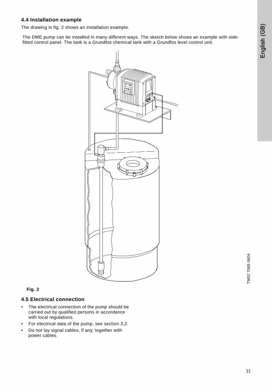
4.4 Installation example
The drawing in fig. 2 shows an installation example.
Fig. 2
4.5 Electrical connection
• The electrical connection of the pump should be carried out by qualified persons in accordance with local regulations.
• For electrical data of the pump, see section 3.2.
• Do not lay signal cables, if any, together with power cables.
The DME pump can be installed in many different ways. The sketch below shows an example with side-fitted control panel. The tank is a Grundfos chemical tank with a Grundfos level control unit.
TM
02
70
65
06
04
11

English (GB)
4.6 Connection overview
Fig. 3
Cable 1: Input for analog signal, pulse signal and diaphragm leakage
* Grundfos diaphragm leakage sensor, product number 96534443
Cable 2: Alarm relay output
TM
02
70
69
03
07
Cable 1.See table below
Cable 2.See table below
Cable 3.See table below
Cable 4.See table below
21
3
453
1
42
31
23
1
5 2
52
2
3 1
134
52
134
213
4
Number / colour 1 / brown 2 / white 3 / blue 4 / black 5 / grey
Function
Analog (–) 4-20 mA
input(+) 4-20 mA
input
Pulse Potential-free Potential-free
Pulse 5 V Ground
Number / colour 2 / black 3 / brown 4 / blue
Diaphragm leakage* 5 V PNP Ground
Number / colour 1 / brown 2 / white 3 / blue
Function
Alarm relay Common Normally open Normally closed
12

Engl
ish
(GB)
Cable 3: Input for dosing stop and dosing monitoring or dosing output
* Open collector (NPN) can be used for a relay or a lamp.
Fig. 4
Cable 4: Level input
* The function of the potential-free contact sets can be selected via the control panel (NO = normally open and NC = normally closed), see section 5.21.
Number / colour 1 / brown 2 / white 3 / blue 4 / black 5 / grey
Function
Dosing stop (input) 5 V Ground
Dosing stop (input) Potential-free Potential-free
Dosing monitoring Potential-free Potential-free
Dosing monitoring Ground 5 V
Dosing output(pump running)
Open collector (NPN)*
Ground
1. Using the internal 5 VDC power supply:Max. current: 100 mA
2. Using an external power supply:Max. 24 VDC - 100 mA
TM
03
786
8 5
006
TM
03
786
9 5
006
Relay
Lamp
Power
Lamp
24 VDC
Number / colour 1 / brown 2 / white 3 / blue 4 / black
Function
Empty tank Potential-free* Potential-free*
Empty tank 5 V Ground
Low level Potential-free* Potential-free*
Low level 5 V Ground
13

English (GB)
5. Functions
5.1 Control panel
Fig. 5
TM
02
70
68
25
03
100%
LCD display.See section 5.8
Navigation/settings.
See section 5.8
Green indicatorlight.
See section 5.6
Maximum capacity(priming).
See section 5.3
Red indicator light.See section 5.6
M12 connectionanalog/pulse /leakage input.See sections
5.11, 5.12, 5.5
Cable forProfibus control.See section 5.7
Connection alarm relay.
See section 5.6
Power supply
M12 connection level control. See section 5.4
M12 connection stop dosing. See section 5.2
On/off button. See section 5.8
Navigation/ settings.See section 5.8
Menu. See section 5.8
14

Engl
ish
(GB)
5.2 Start/stop of pump
The pump can be started/stopped in two different ways:
• Locally on the pump control panel.
• By means of an external on/off switch. See connection overview in section 4.6.
5.3 Priming/venting of pump
The pump control panel incorporates a button. Press this button if the maximum pump capacity is required over a short period, e.g. during start-up. When the button is released, the pump automatically returns to the previous operating mode.
During priming/venting, it is recommended to let the pump run without a counter pressure or to open the vent valve.
Note: When the buttons and are pressed simultaneously, the pump can be set to run for a specific number of seconds at maximum capacity. The remaining number of seconds will appear in the display. The maximum value is 300 seconds.
5.4 Level control
The pump can be fitted with a level control unit for monitoring of the chemical level in the tank.
The pump can react to two level signals. The pump will react differently, depending on the influence on the individual level sensors.
For connection of the level control unit and alarm output, see section 4.6.
5.5 Diaphragm leakage sensor
The pump can be fitted with a diaphragm leakage sensor, which detects diaphragm leakage.
The sensor should be connected to the drain hole in the dosing head.
In case of diaphragm leakage, the signal from the sensor generates an alarm and the alarm relay will be activated. See also section 5.6.
For connection of the diaphragm leakage sensor, see section 4.6.
Level sensors Pump reaction
Upper sensor activated(closed contact)
• Red indicator light is on.
• Pump running.
• Alarm relay activated.
Lower sensor activated(closed contact)
• Red indicator light is on.
• Pump stopped.
• Alarm relay activated.
100%
100%
15

English (GB)
5.6 Alarm output and indicator lights
The green and red indicator lights on the pump are used for operating and fault indication.
In control variant "AR", the pump can activate an external alarm signal by means of a built-in alarm relay which must only be connected to a safety extra low voltage (SELV) connection.
The alarm signal is activated by means of an internal potential-free contact.
The functions of the indicator lights and the built-in alarm relay appear from the table below.
NoteConnect the alarm relay only to voltages which comply with the SELV requirements in EN/IEC 60 335-1.
Condition Green LED Red LED Display Alarm output
Pump running On Off Normal indication
Set to stop Flashing Off Normal indication
Pump fault Off On EEPROM
Supply failure Off Off Off
Pump running, low chemical level1 On On LOW
Empty tank1 Off On EMPTY
Analog signal < 2 mA
Off On NO mA
The pump is running, but the dosed quantity is too small according to the signal from the dosing monitor2
On On NO FLOW
Overheating Off On MAX. TEMP.
Internal communication fault
Off On INT. COM.
Internal Hall fault3 Off On HALL
Diaphragm leakage4 Off On LEAKAGE
1 32NC NO C
1 32NC NO C
1 2 3NC NO C
1 32NC NO C
1 2 3NC NO C
1 2 3NC NO C
1 2 3NC NO C
1 2 3NC NO C
1 2 3NC NO C
1 2 3NC NO C
1 2 3NC NO C
1 2 3NC NO C
16
Engl
ish
(GB)
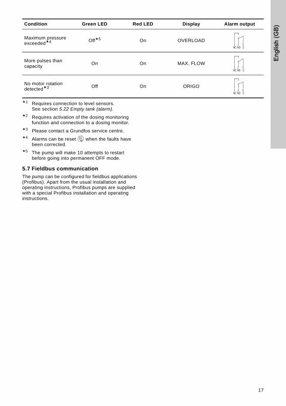
1 Requires connection to level sensors.See section 5.22 Empty tank (alarm).
2 Requires activation of the dosing monitoring function and connection to a dosing monitor.
3 Please contact a Grundfos service centre.4 Alarms can be reset when the faults have
been corrected.5 The pump will make 10 attempts to restart
before going into permanent OFF mode.
5.7 Fieldbus communication
The pump can be configured for fieldbus applications (Profibus). Apart from the usual installation and operating instructions, Profibus pumps are supplied with a special Profibus installation and operating instructions.
Maximum pressure exceeded4 Off5 On OVERLOAD
More pulses than capacity
On On MAX. FLOW
No motor rotation detected3 Off On ORIGO
Condition Green LED Red LED Display Alarm output
1 2 3NC NO C
1 2 3NC NO C
1 2 3NC NO C
17

English (GB)
5.8 Menu
The pump features a user-friendly menu which is activated by pressing the button. During start-up, all texts will appear in English language. To select language, see section 5.20.
All menu items are described in the following sections. When appears at a menu item, it means that this item is activated. By selecting "RETURN" anywhere in the menu structure, you will return to the operating display without changes.
Fig. 6
Applies only to versions with Profibus
See section 5.10 See section 5.25
See section 5.11 See section 5.18
See section 5.12 See section 5.19
See section 5.13 See section 5.20
See section 5.14 See section 5.16
See section 5.15 See section 5.21
See section 7. See section 5.22
See section 5.17 See section 5.23
18

Engl
ish
(GB)
5.9 Operating modes
Note: The displayed l and ml values are only reliable if the pump has been calibrated to the actual installation, see section 7.
The pump can run in five different operating modes:
• Manual
• Pulse
• Analog
• Timer (internal batch control)
• Batch (external batch control)
See description in the following sections.
5.10 Manual
The pump is dosing as constantly and evenly as possible, without any external signals.
Set the quantity to be dosed in l/h or ml/h. The pump automatically changes between the measuring units.
Setting range:
DME 60: 75 ml/h - 60 l/hDME 150: 200 ml/h - 150 l/hDME 375: 500 ml/h - 375 l/hDME 940: 1200 ml/h - 940 l/h
Fig. 7
5.11 Pulse
The pump is dosing according to an external pulse signal, i.e. a water meter with pulse output or a controller.
Set the quantity to be dosed per pulse in ml/pulse. The pump adjusts its capacity according to two factors:
• Frequency of external pulses.
• The set quantity per pulse.
The pump measures the time between two pulses and then calculates the speed giving the capacity required (set quantity per pulse multiplied by the pulse frequency).
The pump does not start until it has received the second pulse, and thus it delivers a constant flow as in the case of "manual" control. The pump calculates a speed for each pulse received.
The pump stops
• when the time between two pulses is three times longer than the time between the two previous pulses, or
• if the time between two pulses exceeds 2 minutes.
The pump will operate at the latest calculated speed until one of the two cases occurs.
The pump stops at the point reached in its duty cycle and starts at this point again having received two new pulses.
Setting range:
DME 60: 0.000625 ml/pulse - 120 ml/pulseDME 150: 0.00156 ml/pulse - 300 ml/pulseDME 375: 0.00392 ml/pulse - 750 ml/pulseDME 940: 0.00980 ml/pulse - 1880 ml/pulse
Fig. 8
If the set quantity per pulse multiplied by the pulse frequency exceeds the pump capacity, the pump will run at maximum capacity. Excess pulses will be ignored and "MAX. FLOW" will appear in the display.
Set value
Set quantity in ml/pulse
Actual capacity inml/h or l/h
19
English (GB)
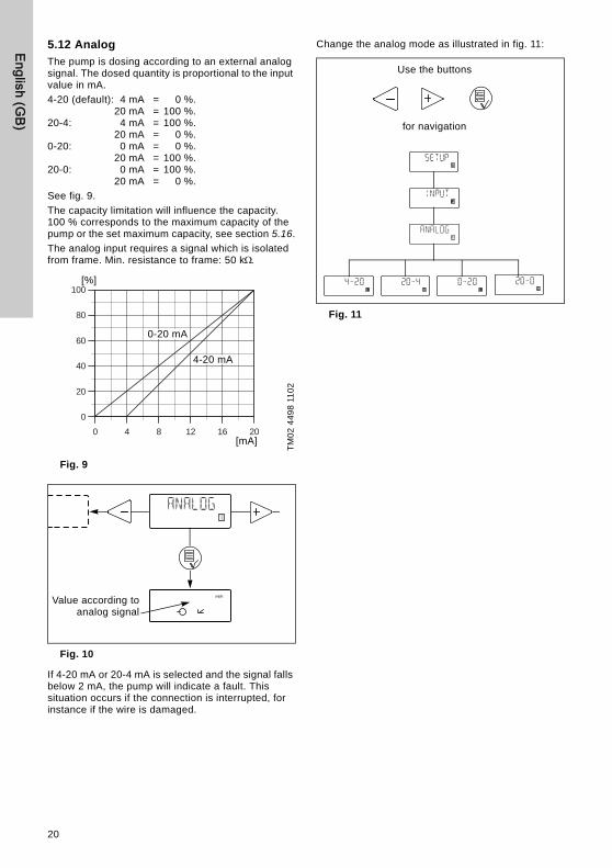
5.12 Analog
The pump is dosing according to an external analog signal. The dosed quantity is proportional to the input value in mA.
4-20 (default): 4 mA = 0 %.20 mA = 100 %.
20-4: 4 mA = 100 %.20 mA = 0 %.
0-20: 0 mA = 0 %.20 mA = 100 %.
20-0: 0 mA = 100 %.20 mA = 0 %.
See fig. 9.
The capacity limitation will influence the capacity. 100 % corresponds to the maximum capacity of the pump or the set maximum capacity, see section 5.16.
The analog input requires a signal which is isolated from frame. Min. resistance to frame: 50 k
Fig. 9
Fig. 10
If 4-20 mA or 20-4 mA is selected and the signal falls below 2 mA, the pump will indicate a fault. This situation occurs if the connection is interrupted, for instance if the wire is damaged.
Change the analog mode as illustrated in fig. 11:
Fig. 11
TM
02
44
98
11
02
0 4 8 12 16 20
0
20
40
60
80
100[%]
0-20 mA
[mA]
4-20 mA
Value according toanalog signal
Use the buttons
for navigation
20

Engl
ish
(GB)
5.13 Timer
The pump is dosing the set quantity in batches at the maximum capacity or the set maximum capacity, see section 5.16.
The time until the first dosing "NX" and the following sequences "IN" can be set in minutes, hours and days. The maximum time limit is 9 days, 23 hours and 59 minutes (9:23:59). The lowest acceptable value is 1 minute. The internal timer continues even if the pump is stopped by means of the on/off button, empty tank or stop signal, see fig. 12.
During operation, "NX" will always count down from "IN" to zero. In this way, the remaining time until the next batch can always be read.
"IN" must be higher than the time required to perform one batch. If "IN" is lower, the next batch will be ignored.
In case of supply failure, the set quantity to be dosed, the "IN" time and the remaining "NX" time are stored. When the supply is reconnected, the pump will start up with the "NX" time at the time of the supply failure. In this way, the timer cycle will continue, but it has been delayed by the duration of the supply failure.
Fig. 12
Setting range:
DME 60: 6.25 ml/batch - 120 l/batchDME 150: 15.6 ml/batch - 300 l/batchDME 375: 39.1 ml/batch - 750 l/batchDME 940: 97.9 ml/batch - 1880 l/batch
Only values corresponding to complete dosing strokes (according to the calibration factor) can be selected. The minimum setting depends on the calibration factor. The minimum setting shown above corresponds to the default calibration value.
Example:
If the calibration factor is 625 (= 6.25 ml/stroke), the minimum settable value in timer or batch mode will be 6.25 ml (= 1 stroke) -> the next will be 12.5 ml (= 2 strokes), etc.
These steps will continue up to a value corresponding to 100 dosing strokes. Above this value, the setting range has standard steps as in other operating modes.
If the calibration factor is changed after the setting of timer or batch mode, the pump will automatically recalculate a new number of dosing strokes per batch and change the display value to the nearest possible value compared to the first one set.
Fig. 13
TM
01
89
42
09
00
NX
IN
Quantity per batch
Set quantity per batch
Set IN value in days
Set IN value in hours
Set IN value in minutes
Set NX value in days
Set NX value in hours
Set NX value in minutes
21

English (GB)
5.14 Batch
The pump is dosing the set quantity in batches at the maximum capacity or the set maximum capacity, see section 5.16.
The quantity is dosed every time the pump receives an external pulse.
If the pump receives new pulses before the previous batch is performed, these pulses will be ignored.
Fig. 14
The setting range is the same as for Timer, see section 5.13.
Fig. 15
5.15 Anti-cavitation
The pump features an anti-cavitation function. When this function is selected, the pump extends its suction stroke, resulting in optimized priming.
The anti-cavitation function is used:
• when pumping liquids of high viscosity
• in the case of a long suction tube
• in the case of a high suction lift.
Depending on the circumstances, the motor speed during the suction stroke can be reduced by 75 %, 50 % or 25 % compared to the normal motor speed during the suction stroke.
The maximum pump capacity is reduced when the anti-cavitation function is selected. See section 3.1 Mechanical data.
Fig. 16
TM
01
89
47
09
00
Quantity per batch
Pulse Pulse
Set value per batch
Operating display
22

Engl
ish
(GB)
5.16 Capacity limitation
This function offers the possibility of reducing the maximum pump capacity (MAX. CAP.). It influences the functions in which the pump is normally operating at maximum capacity.
Under normal operating conditions, the pump cannot operate at a capacity which is higher than the one stated in the display. This does not apply to the maximum capacity button , see section 5.3.
Fig. 17
5.17 Counters
The pump can display "non-resettable" counters for:
• "QUANTITY" Accumulated value of dosed quantity in litres or US gallons.
• "STROKES" Accumulated number of dosing strokes.
• "HOURS" Accumulated number of operating hours.
• "POWER ON" Accumulated number of times the electricity supply has been switched on.
Fig. 18
100%
Operating display
Set maximum capacity
Total dosedquantity
Total numberof strokes
Total number ofoperating hours
Total numberof starts
Operating display
23

English (GB)
5.18 Resetting
When "DEFAULT" is activated, the pump will return to the factory settings.
Note: The calibration is also set back to the default setting. This means that a new calibration is required when the "DEFAULT" function has been used.
Default settings are the factory settings of standard pumps. Select "DEFAULT" in the "SETUP" menu.
Default settings:
Fig. 19
5.19 Return
Fig. 20
The "RETURN" function makes it possible to return from any level in the menu to the operating display without changes after the menu functions have been used.
5.20 Language
The display text can be displayed in one of the following languages:
• English
• German
• French
• Italian
• Spanish
• Portuguese
• Dutch
• Swedish
• Finnish
• Danish
• Czech
• Slovak
• Polish
• Russian
Operating mode: Manual
Capacity: Maximum capacity
Control panel lock: Unlocked
Default lock code: 2583
Anti-cavitation: Not active
Analog signal: 4-20 mA
Digital inputs: NO (normally open)
Capacity limitation: Maximum capacity
Alarm reset required to restart the pump
Dosing monitoring: Off
Language: English
Units: Metric
Operating display Operating display without changes
24

Engl
ish
(GB)
Fig. 21
5.21 Input setup
Fig. 22 shows all possible settings.
The inputs for level, stop dosing and diaphragm leakage can be changed from NO (normally open) to NC (normally closed) function. If changed, the inputs must be short-circuited in normal operation. The dosing monitoring input can be changed from "OFF" to "ON".
For the analog input, one of the following signal types can be selected:
• 4-20 mA (default)
• 20-4 mA
• 0-20 mA
• 20-0 mA.
See also section 5.12 Analog.
Fig. 22
Operating display Operating display Operating display without changes
Use the buttons
for navigation
25

English (GB)
5.22 Empty tank (alarm)
The alarm function can be set to "AUT. RES." or "MAN. RES.". This function is used when the level sensor indicates "EMPTY".
The alarm can be reset automatically (AUT. RES.) or manually (MAN. RES.).
For more information about other alarm functions, see section 5.6 Alarm output and indicator lights.
5.23 Measuring units
It is possible to select metric units (litre/millilitre) or US units (gallons).
Metric measuring units:
• In manual and analog modes, set the quantity to be dosed in litres per hour (l/h) or millilitres per hour (ml/h).
• In pulse mode, set the quantity to be dosed in ml/pulse. The actual capacity is indicated in litres per hour (l/h) or millilitres per hour (ml/h).
• For calibration, set the quantity to be dosed in ml per 100 strokes.
• In timer and batch modes, set the quantity to be dosed in litres (l) or millilitres (ml).
• Under the "QUANTITY" menu item in the "COUNTERS" menu, the dosed quantity is indicated in litres.
US measuring units:
• In manual and analog modes, set the quantity to be dosed in gallons per hour (gph).
• In pulse mode, set the quantity to be dosed in ml/pulse. The actual capacity is indicated in gallons per hour (gph).
• For calibration, set the quantity to be dosed in ml per 100 strokes.
• In timer and batch modes, set the quantity to be dosed in gallons (gal).
• Under the "QUANTITY" menu item in the "COUNTERS" menu, the dosed quantity is indicated in US gallons (gal).
Fig. 23
Operating display Operating display
3 x
26

Engl
ish
(GB)
5.24 Dosing monitoring
The pump incorporates a dosing monitoring input (see connection overview in fig. 3).
Fig. 24
The dosing monitoring input is designed to receive a potential-free pulse signal from a dosing monitor.
The dosing monitoring input feature enables the pump to react on gas accumulation in the suction line.
A dosing monitor must always be connected to the suction side of the pump.
2 x
3 x
27
English (GB)
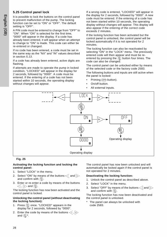
5.25 Control panel lock
It is possible to lock the buttons on the control panel to prevent malfunction of the pump. The locking function can be set to "ON" or "OFF". The default setting is "OFF".
A PIN code must be entered to change from "OFF" to "ON". When "ON" is selected for the first time, "0000" will appear in the display. If a code has already been entered, it will appear when an attempt to change to "ON" is made. This code can either be re-entered or changed.
If no code has been entered, a code must be set in the same way as the "NX" and "IN" values described in section 5.13.
If a code has already been entered, active digits are flashing.
If attempts are made to operate the pump in locked condition, "LOCKED" will appear in the display for 2 seconds, followed by "0000". A code must be entered. If the entering of a code has not been started within 10 seconds, the operating display without changes will appear.
If a wrong code is entered, "LOCKED" will appear in the display for 2 seconds, followed by "0000". A new code must be entered. If the entering of a code has not been started within 10 seconds, the operating display without changes will appear. This display will also appear if the entering of the correct code exceeds 2 minutes.
If the locking function has been activated but the control panel is unlocked, the control panel will be locked automatically if it is not operated for 2 minutes.
The locking function can also be reactivated by selecting "ON" in the "LOCK" menu. The previously entered code will then appear and must be re-entered by pressing the button four times. The code can also be changed.
The control panel can be unlocked either by means of the selected code or the factory code 2583.
The following buttons and inputs are still active when the panel is locked:
• Priming ( -button).
• On/off button.
• All external inputs.
Fig. 25
Activating the locking function and locking the control panel:
1. Select "LOCK" in the menu.
2. Select "ON" by means of the buttons and and confirm with .
3. Enter or re-enter a code by means of the buttons , and .
The locking function has now been activated and the control panel is locked.
Unlocking the control panel (without deactivating the locking function):
1. Press once. "LOCKED" appears in the display for 2 seconds, followed by "0000".
2. Enter the code by means of the buttons , and *.
The control panel has now been unlocked and will automatically be locked again if the control panel is not operated for 2 minutes.
Deactivating the locking function:
1. Unlock the control panel as described above.
2. Select "LOCK" in the menu.
3. Select "OFF" by means of the buttons and and confirm with .
The locking function has now been deactivated and the control panel is unlocked.
* The panel can always be unlocked with code 2583.
100%
Operating display
Operating display
28

Engl
ish
(GB)
6. Start-up
If the pump is not operating satisfactorily, see section 10. Fault finding chart.
Step Action
1 Prior to start-up, retighten the dosing head screws:• Cross-tighten the screws to 5.5 Nm (+ 0.5/– 0 Nm).
2
Connect the hoses/pipes:• Connect the suction and dosing tubes/pipes to the pump. • Connect a tube to the vent valve, if required, and lead the hose to
the tank.
3Connect the cables:• Connect the control/level cables, if any, to the pump, see
section 4.6.
4
Switch on the electricity supply:• The display is on.• The green indicator light is flashing (the pump has stopped).• Select language, if required, see section 5.20.
5
Select the operating mode (see section 5.9):• Manual.• Pulse.• Analog.• Timer.• Batch.
6Start the pump:• Start the pump by pressing the on/off button.• The green indicator light is permanently on.
7
Priming/venting:• Press the button on the pump control panel and let the pump
run without a counter pressure. Open the vent valve, if required.When the buttons and are pressed simultaneously during priming, the pump can be set to run for a specific number of seconds at maximum capacity.
8Calibration:• When the pump has been primed and is running at the right
counter pressure, calibrate the pump, see section 7.
100%
100%
100%
100%
100%
29

English (GB)
7. CalibrationIt is important that the pump is calibrated after installation to ensure that the correct value (ml/h or l/h) appears in the display.
The calibration can be carried out in two different ways:
• Direct calibration.The dosed quantity of 100 strokes is measured directly. See section 7.1.
• Check calibration. See section 7.2.
Fig. 26
Operating display without changes
Set value. See section 7.2
Operating display Operating display
The pumpperforms 100
dosing strokes
30

Engl
ish
(GB)
7.1 Direct calibration
Before calibration, make sure:
• that the pump is installed with foot valve, injection valve, etc. in the existing system.
• that the pump is running at the counter pressure it is supposed to operate at (adjust the counter pressure valve, if required).
• that the pump is operating with the correct suction lift.
To carry out a direct calibration, proceed as follows:
Action Pump display
1. Prime the dosing head and the suction tubing.
2. Stop the pump. The green LED is flashing.
3. Fill a graduated glass with dosing liquid, Q1.
DME 60: approx. 1.5 lDME 150: approx. 2.5 lDME 375: approx. 6 lDME 940: approx. 14 l
4. Read and note the quantity Q1.
5. Place the suction tubing in the graduated glass.
TM
02
70
67
25
03
6. Go to the calibration menu, see section 5.8.
7. Press the button twice.
8. The pump is performing 100 dosing strokes.
9. The factory-calibration value appears in the display.
10. Remove the suction tubing from the graduated glass and read Q2.
11. Set the display value to Qd = Q1 – Q2.
12. Confirm with the button.
13. The pump is now calibrated and returns to the operating display.
Set value to Qd
Operating display
Q1
Q2
Qd
31

English (GB)
7.2 Check calibration
In check calibration, the calibration value is calculated by reading the consumption of chemical in a specific period and comparing this with the number of dosing strokes performed in the same period.
This calibration method is very accurate and especially suitable for check calibration after long periods of operation or if direct calibration is impossible. The calibration can for instance be carried out when the chemical tank is replaced or filled.
To carry out a check calibration, proceed as follows:
1. Stop the pump by pressing the button.
2. Read the counter and note the number of dosing strokes, see section 5.17.
3. Read and note the quantity in the chemical tank.
4. Start the pump by pressing the button and let it run for at least 1 hour. The longer the pump is operating, the more accurate the calibration will be.
5. Stop the pump by pressing the button.
6. Read the counter and note the number of dosing strokes, see section 5.17.
7. Read and note the quantity in the chemical tank.
8. Calculate the dosed quantity in ml and the number of dosing strokes performed during the operating period.
9. Calculate the calibration value as follows:(dosed quantity in ml/dosing strokes) x 100.
10. Set the calculated value in the calibration menu.
8. MaintenanceThe pump is maintenance-free. However, it is recommended to keep the pump clean.
The dosing pump is produced according to the highest quality standards and has long life. The pump incorporates wear parts such as diaphragm, valve seat and valve balls.
To ensure long life and to reduce the risk of disturbance of operation, visual checks should be carried out regularly.
It is possible to order dosing heads, valves and diaphragms in materials which are suitable for the specific liquid to be pumped. See the product numbers at the end of these instructions.
9. ServiceBefore returning the pump to Grundfos for service, the safety declaration at the end of these instructions must be filled in by authorized personnel and attached to the pump in a visible position.
Note: If a pump has been used for a liquid which is injurious to health or toxic, the pump will be classified as contaminated.
If Grundfos is requested to service the pump, it must be ensured that the pump is free from substances that can be injurious to health or toxic. If the pump has been used for such substances, the pump must be cleaned before it is returned.
If proper cleaning is not possible, all relevant information about the chemical must be provided.
If the above is not fulfilled, Grundfos can refuse to accept the pump for service. Possible costs of returning the pump are paid by the customer.
The safety declaration can be found at the end of these instructions (only in English).
Note: The replacement of the supply cable must be carried out by an authorised Grundfos service workshop.
32

Engl
ish
(GB)
10. Fault finding chart
11. Disposal This product and all its associated parts must be disposed of in an environmentally friendly manner. Use appropriate waste collection services. If there is no such facility or the facility refuses to accept the materials used in the product, the product can be sent to the nearest Grundfos company or Grundfos service centre.
Fault Cause Remedy
The dosing has stopped or the output is too low.
Valves leaking or blocked. Check and clean valves.
Valves incorrectly installed.
Remove and fit valves. Check that the arrow on the valve casing is pointing in the liquid flow direction. Check that all O-rings have been fitted correctly.
Suction valve or suction pipe/hose leaking or blocked.
Clean and seal the suction pipe/hose.
Suction lift too high.Install the pump in a lower position.
Install a priming tank.
Viscosity too high.
Select the anti-cavitation function, see section 5.15.
Install a pipe/hose with larger cross-section.
Fit spring-loaded valves.
Pump out of calibration. Calibrate the pump, see section 7.
Pump dosing too little or too much.
Pump out of calibration. Calibrate the pump, see section 7.
Pump dosing irregularly.
Valves leaking or blocked. Check and clean the valves.
Leakage from drain hole.
Diaphragm defective. Install a new diaphragm.
Frequent diaphragm failures.
Diaphragm not fastened properly.Install a new diaphragm and ensure that the diaphragm is fastened properly.
Counter-pressure too high (measured at the pump discharge port).
Check the system. Check the injection valve.
Sediment in dosing head. Clean/flush the dosing head.
Subject to alterations.
33

Appendix
325
Appendix 1
Dimensions
TM
02
70
62
25
03
DME 60 DME 150 DME 375 DME 940
A = [mm] 176 176 238 238
B = [mm] 198 198 218 218
C = [mm] 331 345 471 496
D = [mm] 284 284 364 364
E = [mm] 180 180 230 230
F = [mm] 444 444 540 539
G = [mm] 41 28 31 6
H = [mm] 74 74 95 95
I = [mm] 187 187 246 246

Appendix
326
Appendix 1
Safety declaration
Please copy, fill in and sign this sheet and attach it to the pump returned for service.
We hereby declare that this product:
Product type:____________________________
Model number:_________________________
No media or water:_________________________
A chemical solution, name:_____________________
(see pump nameplate)
is free from hazardous chemicals, biological and radioactive substances.
Fault descriptionPlease make a circle around the damaged part.
In the case of an electrical or functional fault, please mark the cabinet.
Please give a short description of the fault:
_________________ _________________
Date and signature Company stamp
TM
02
89
55
11
04

Grundfos com
panies
ArgentinaBombas GRUNDFOS de Argentina S.A.Ruta Panamericana km. 37.500 Lote 34A1619 - GarinPcia. de Buenos AiresPhone: +54-3327 414 444Telefax: +54-3327 411 111
AustraliaGRUNDFOS Pumps Pty. Ltd. P.O. Box 2040 Regency Park South Australia 5942 Phone: +61-8-8461-4611 Telefax: +61-8-8340 0155
AustriaGRUNDFOS Pumpen Vertrieb Ges.m.b.H.Grundfosstraße 2 A-5082 Grödig/Salzburg Tel.: +43-6246-883-0 Telefax: +43-6246-883-30
BelgiumN.V. GRUNDFOS Bellux S.A. Boomsesteenweg 81-83 B-2630 Aartselaar Tél.: +32-3-870 7300 Télécopie: +32-3-870 7301
BelorussiaПредставительство ГРУНДФОС в Минске220123, Минск,ул. В. Хоружей, 22, оф. 1105Тел.: +(37517) 233 97 65Факс: (37517) 233 9769E-mail: [email protected]
Bosnia/HerzegovinaGRUNDFOS SarajevoTrg Heroja 16,BiH-71000 SarajevoPhone: +387 33 713 290Telefax: +387 33 659 079e-mail: [email protected]
BrazilBOMBAS GRUNDFOS DO BRASILAv. Humberto de Alencar Castelo Branco, 630CEP 09850 - 300São Bernardo do Campo - SPPhone: +55-11 4393 5533Telefax: +55-11 4343 5015
BulgariaGrundfos Bulgaria EOODSlatina DistrictIztochna Tangenta street no. 100BG - 1592 SofiaTel. +359 2 49 22 200Fax. +359 2 49 22 201email: [email protected]
CanadaGRUNDFOS Canada Inc. 2941 Brighton Road Oakville, Ontario L6H 6C9 Phone: +1-905 829 9533 Telefax: +1-905 829 9512
ChinaGrundfos AlldosDosing & DisinfectionALLDOS (Shanghai) Water Technology Co. Ltd.West Unit, 1 Floor, No. 2 Building (T 4-2)278 Jinhu Road, Jin Qiao Export Processing ZonePudong New Area Shanghai, 201206Phone: +86 21 5055 1012Telefax: +86 21 5032 0596E-mail: [email protected]
ChinaGRUNDFOS Pumps (Shanghai) Co. Ltd.22 Floor, Xin Hua Lian Building755-775 Huai Hai Rd, (M)Shanghai 200020PRCPhone: +86-512-67 61 11 80Telefax: +86-512-67 61 81 67
CroatiaGRUNDFOS CROATIA d.o.o.Cebini 37, BuzinHR-10010 ZagrebPhone: +385 1 6595 400 Telefax: +385 1 6595 499www.grundfos.hr
Czech RepublicGRUNDFOS s.r.o.Čapkovského 21779 00 OlomoucPhone: +420-585-716 111Telefax: +420-585-716 299
DenmarkGRUNDFOS DK A/S Martin Bachs Vej 3 DK-8850 Bjerringbro Tlf.: +45-87 50 50 50 Telefax: +45-87 50 51 51 E-mail: [email protected]/DK
EstoniaGRUNDFOS Pumps Eesti OÜPeterburi tee 92G11415 TallinnTel: + 372 606 1690Fax: + 372 606 1691
FinlandOY GRUNDFOS Pumput AB Mestarintie 11 FIN-01730 Vantaa Phone: +358-3066 5650 Telefax: +358-3066 56550
FrancePompes GRUNDFOS Distribution S.A. Parc d’Activités de Chesnes 57, rue de Malacombe F-38290 St. Quentin Fallavier (Lyon) Tél.: +33-4 74 82 15 15 Télécopie: +33-4 74 94 10 51
GermanyGRUNDFOS Water Treatment GmbHReetzstraße 85D-76327 Pfinztal (Söllingen)Tel.: +49 7240 61-0 Telefax: +49 7240 61-177E-mail: [email protected]
GermanyGRUNDFOS GMBHSchlüterstr. 33D-40699 ErkrathTel.: +49-(0) 211 929 69-0 Telefax: +49-(0) 211 929 69-3799E-mail: [email protected] in Deutschland:E-mail: [email protected]
GreeceGRUNDFOS Hellas A.E.B.E. 20th km. Athinon-Markopoulou Av. P.O. Box 71 GR-19002 Peania Phone: +0030-210-66 83 400 Telefax: +0030-210-66 46 273
Hong KongGRUNDFOS Pumps (Hong Kong) Ltd. Unit 1, Ground floor Siu Wai Industrial Centre 29-33 Wing Hong Street & 68 King Lam Street, Cheung Sha Wan Kowloon Phone: +852-27861706 / 27861741 Telefax: +852-27858664
HungaryGRUNDFOS Hungária Kft.Park u. 8H-2045 Törökbálint, Phone: +36-23 511 110Telefax: +36-23 511 111
IndiaGRUNDFOS Pumps India Private Limited118 Old Mahabalipuram RoadThoraipakkamChennai 600 096Phone: +91-44 2496 6800
IndonesiaPT GRUNDFOS Pompa Jl. Rawa Sumur III, Blok III / CC-1 Kawasan Industri, Pulogadung Jakarta 13930 Phone: +62-21-460 6909 Telefax: +62-21-460 6910 / 460 6901
IrelandGRUNDFOS (Ireland) Ltd. Unit A, Merrywell Business ParkBallymount Road LowerDublin 12 Phone: +353-1-4089 800 Telefax: +353-1-4089 830
ItalyGRUNDFOS Pompe Italia S.r.l. Via Gran Sasso 4I-20060 Truccazzano (Milano)Tel.: +39-02-95838112 Telefax: +39-02-95309290 / 95838461
JapanGRUNDFOS Pumps K.K.Gotanda Metalion Bldg. 5F,5-21-15, Higashi-gotandaShiagawa-ku, Tokyo, 141-0022 JapanPhone: +81 35 448 1391Telefax: +81 35 448 9619
KoreaGRUNDFOS Pumps Korea Ltd.6th Floor, Aju Building 679-5Yeoksam-dong, Kangnam-ku, 135-916Seoul, KoreaPhone: +82-2-5317 600Telefax: +82-2-5633 725
LatviaSIA GRUNDFOS Pumps Latvia Deglava biznesa centrsAugusta Deglava ielā 60, LV-1035, Rīga,Tālr.: + 371 714 9640, 7 149 641Fakss: + 371 914 9646
LithuaniaGRUNDFOS Pumps UABSmolensko g. 6LT-03201 VilniusTel: + 370 52 395 430Fax: + 370 52 395 431
MalaysiaGRUNDFOS Pumps Sdn. Bhd.7 Jalan Peguam U1/25Glenmarie Industrial Park40150 Shah AlamSelangor Phone: +60-3-5569 2922Telefax: +60-3-5569 2866

Gru
ndfo
s co
mpa
nies
MéxicoBombas GRUNDFOS de México S.A. de C.V. Boulevard TLC No. 15Parque Industrial Stiva AeropuertoApodaca, N.L. 66600Phone: +52-81-8144 4000 Telefax: +52-81-8144 4010
NetherlandsGRUNDFOS NetherlandsVeluwezoom 351326 AE AlmerePostbus 22015 1302 CA ALMERE Tel.: +31-88-478 6336 Telefax: +31-88-478 6332 E-mail: [email protected]
New ZealandGRUNDFOS Pumps NZ Ltd.17 Beatrice Tinsley CrescentNorth Harbour Industrial EstateAlbany, AucklandPhone: +64-9-415 3240Telefax: +64-9-415 3250
NorwayGRUNDFOS Pumper A/S Strømsveien 344 Postboks 235, Leirdal N-1011 Oslo Tlf.: +47-22 90 47 00 Telefax: +47-22 32 21 50
PolandGRUNDFOS Pompy Sp. z o.o.ul. Klonowa 23Baranowo k. PoznaniaPL-62-081 PrzeźmierowoTel: (+48-61) 650 13 00Fax: (+48-61) 650 13 50
PortugalBombas GRUNDFOS Portugal, S.A. Rua Calvet de Magalhães, 241Apartado 1079P-2770-153 Paço de ArcosTel.: +351-21-440 76 00Telefax: +351-21-440 76 90
RomâniaGRUNDFOS Pompe România SRLBd. Biruintei, nr 103 Pantelimon county IlfovPhone: +40 21 200 4100Telefax: +40 21 200 4101E-mail: [email protected]
RussiaООО ГрундфосРоссия, 109544 Москва, ул. Школьная 39Тел. (+7) 495 737 30 00, 564 88 00Факс (+7) 495 737 75 36, 564 88 11E-mail [email protected]
Serbia GRUNDFOS Predstavništvo BeogradDr. Milutina Ivkovića 2a/29YU-11000 Beograd Phone: +381 11 26 47 877 / 11 26 47 496Telefax: +381 11 26 48 340
SingaporeGRUNDFOS (Singapore) Pte. Ltd. 24 Tuas West Road Jurong Town Singapore 638381 Phone: +65-6865 1222 Telefax: +65-6861 8402
SloveniaGRUNDFOS d.o.o.Šlandrova 8b, SI-1231 Ljubljana-ČrnučePhone: +386 1 568 0610Telefax: +386 1 568 0619E-mail: [email protected]
South AfricaGrundfos (PTY) Ltd.Corner Mountjoy and George Allen RoadsWilbart Ext. 2Bedfordview 2008Phone: (+27) 11 579 4800Fax: (+27) 11 455 6066E-mail: [email protected]
SpainBombas GRUNDFOS España S.A. Camino de la Fuentecilla, s/n E-28110 Algete (Madrid) Tel.: +34-91-848 8800 Telefax: +34-91-628 0465
SwedenGRUNDFOS AB (Box 333) Lunnagårdsgatan 6 431 24 Mölndal Tel.: +46(0)771-32 23 00 Telefax: +46(0)31-331 94 60
SwitzerlandGRUNDFOS ALLDOS International AGSchönmattstraße 4 CH-4153 ReinachTel.: +41-61-717 5555Telefax: +41-61-717 5500E-mail: [email protected]
SwitzerlandGRUNDFOS Pumpen AG Bruggacherstrasse 10 CH-8117 Fällanden/ZH Tel.: +41-1-806 8111 Telefax: +41-1-806 8115
TaiwanGRUNDFOS Pumps (Taiwan) Ltd. 7 Floor, 219 Min-Chuan Road Taichung, Taiwan, R.O.C. Phone: +886-4-2305 0868Telefax: +886-4-2305 0878
ThailandGRUNDFOS (Thailand) Ltd. 92 Chaloem Phrakiat Rama 9 Road,Dokmai, Pravej, Bangkok 10250Phone: +66-2-725 8999Telefax: +66-2-725 8998
TurkeyGRUNDFOS POMPA San. ve Tic. Ltd. Sti.Gebze Organize Sanayi Bölgesi Ihsan dede Caddesi,2. yol 200. Sokak No. 20441490 Gebze/ KocaeliPhone: +90 - 262-679 7979Telefax: +90 - 262-679 7905E-mail: [email protected]
UkraineТОВ ГРУНДФОС УКРАЇНА 01010 Київ, Вул. Московська 8б, Тел.:(+38 044) 390 40 50 Фах.: (+38 044) 390 40 59E-mail: [email protected]
United Arab EmiratesGRUNDFOS Gulf DistributionP.O. Box 16768Jebel Ali Free ZoneDubaiPhone: +971-4- 8815 166Telefax: +971-4-8815 136
United KingdomGRUNDFOS Pumps Ltd. Grovebury Road Leighton Buzzard/Beds. LU7 8TL Phone: +44-1525-850000 Telefax: +44-1525-850011
U.S.A.GRUNDFOS Pumps Corporation 17100 West 118th TerraceOlathe, Kansas 66061Phone: +1-913-227-3400 Telefax: +1-913-227-3500
UsbekistanПредставительство ГРУНДФОС в Ташкенте700000 Ташкент ул.Усмана Носира 1-й тупик 5Телефон: (3712) 55-68-15Факс: (3712) 53-36-35
Addresses revised 03.11.2010
www.grundfosalldos.com
The name Grundfos, the Grundfos logo, and the payoff Be–Think–Innovate are registrated trademarks owned by Grundfos Management A/S or Grundfos A/S, Denmark. All rights reserved worldwide.
Being responsible is our foundationThinking ahead makes it possible
Innovation is the essence
96527377 0311
Repl. 96527377 0111
ECM: 1065172