Embed Size (px)
Citation preview

Journal of Applied Mechanics Vol.7, pp.233-246 (August 2004) JSCE
EFFECT OF VERTICAL WEB STIFFENERS ON
LATERAL TORSIONAL BUCKLING BEHAVIOR
OF CANTILEVER STEEL I-BEAMS
Mohammed HASSANIEN1, Machaly BAHAA2, Hesham SOBHY3, Ahmed HASSAN4
and Junya INOUE5
1 Ph.D. Student, Dept. of Civil Eng., University of Tokyo
(Hongo 7-3-1, Bunkyo-ku, Tokyo 113-8656, Japan) E-mail: [email protected]
2Dr. Eng., Professor, Dept. of Civil Eng., Cairo University
3Dr. Eng., Professor, Dept. of Civil Eng., Cairo University
4Dr. Eng., Assoc. Professor, Dept. of Civil Eng., Cairo University
5 Member of JSCE, Dr. Eng., Assoc. Professor, Dept. of Civil Eng., University of Tokyo
Lateral torsional buckling often governs design of I-beams. Although vertical web stiffeners are extensively used to provide internal stiffening, their effect on lateral torsional buckling behavior is totally ignored in the design codes. Here, effect of stiffeners on cantilever beams studied under static uniform moment, uniform load, and end concentrated load. Finite element buckling solver has been used and then linear regression analysis for output data of finite element was conducted to produce simplified equation for the critical moment including stiffeners effect. The results show that stiffeners cause significant magnification in the critical moment than the basic critical moment of the case of beam without stiffeners.
Key Words: lateral torsional buckling, cantilever beams, vertical web stiffeners, uniform torsion, warping torsion.
1. INTRODUCTION
It is well known that beams of thin-walled open
cross sections composed of slender component
plates, such as I-sections, are particularly susceptible to lateral torsional buckling. This is because the torsional rigidities of such cross sections are very
low and therefore their resistance to torsional
instability is low. The effects of unbraced length and
end conditions on the elastic lateral torsional buckling load of the beam are rather evident. The
longer the unbraced length and the less resistant the
support can deliver to the beam, the lower the critical lateral buckling load will be1)2)3). Hence, the
optimum method to prevent the lateral torsional
buckling is using lateral bracing to the compression flange to reduce its unsupported length4)5). However,
if the lateral bracing is not feasible the internal stiffening that provided by the vertical web
stiffeners could be used to enhance beam resistance for the lateral torsional buckling6)7).
The main idea behind the expected increase in lateral torsional buckling resistance of beams
depends on connecting the behavior of the tension flange with the behavior of the compression flange
by using the vertical web stiffeners. This reduces,
somewhat, the tendency of the beam to buckle out of
plane in other words it will increase the warping torsion resistance of the beam8)9)10). Some lateral torsional buckling problems have closed form solutions1)11)12) while the others have numerical solutions for different loading, and boundary conditions13). However, on the other hand, codes specifications totally ignored the effect of vertical web stiffeners on the lateral torsional buckling.
Hereafter, cantilever beams have been studied using computer model14) that has been used for linear buckling analysis so that to match the thin-walled beam theory assumptions in buckling analysis. Moreover, different sets of static loading have been considered: Uniform Moment, Uniform Load, and End Concentrated Load. An equation is
presented to take into consideration the effect of vertical web stiffeners on the lateral torsional buckling of cantilever beams for each case of loading. The equations are proposed using linear regression analysis15) on the output of finite element model buckling runs for each set of loading. The concern in this study is regarding allowable stress design methodology (ASD); consequently, studied cases have been adopted for elastic buckling. Vertical web stiffeners are commonly used at the two sides of the web to prevent web distortion through welding processes so in this study stiffeners have been used at both sides of the web.
―233―

2. THEORETICAL BACKGROUND
The elastic buckling moment for a cantilever beam under a uniform moment caused by an end moment Mo applied at the free end can be obtained directly from the solution of the simply supported beam by imagining the beam to be consisted of two cantilevers of equal length joined together at the fixed end. Hence, the critical moment for the cantilever beam can be obtained 1) from equation (1) by replacing L by 2L. Then equation (2) can represent the desired critical moment.
(1)
(2)
For cantilever beams subjected to end concentrated load, Q, acting at distance yQ below their centroids; approximate numerical solutions for the buckling resistance have been reported 13). Fig.1 shows these solutions, in solid lines for top flange loading, which may be approximated by:
(3)
in which,
(4)
(5)
(6)
In this figure Iw is equal to Cw; however, s is a
dimensionless load height parameter. For a
centroidal loading (ƒÃ=0), the variation of the
buckling resistance with the torsion parameter K is
approximately linear, as it is for end moments,
which do not rotate ƒÓL, where ƒÓL is the beam
twisting angle in radians. Moreover, the effect of
load height yQ is demonstrated in Fig.1, and it can
be seen that while bottom flange loading
significantly increase the buckling resistance, top
flange loading may reduce it substantially,
especially for cantilevers with high values of K. The
non-linear effect of load height is suggested by the
approximate formulation of equation (3).
Fig.1 Buckling of cantilever beams with end loads. (N.S. TRAHAIR, 2000)
For cantilever beams subjected to uniformly distributed load q acting at distances yq from their centroids; approximated numerical solutions for the buckling resistances have been reported13). Fig.2 shows these solutions which may be approximated by:
(7)
in which,
(8)
Fig.2 Buckling of cantilever beams under distributed loads. (N.S. TRAHAIR, 2000)
The buckling resistance again varies almost linearly with the torsion parameter K, and is higher
―234―

than the resistance for end load as shown in Fig.1, because the bending moment is generally lower. For loading away from the centroid, the resistance changes non-linearly with the dimensionless load height s, as suggested by the approximate formulation of equation (7).
3. METHODOLOGY AND NUMERICAL MODEL
The cantilever beam has been modeled using the finite elements, thin shell elements (4-nodes Quad element with 6 degrees of freedom at each node). The following are the cases of loading that have been considered in this study as follow:1. Uniform Moment (Unit Moment): The uniformbending moment has been modeled as a
concentrated bending moment at the free end of the
cantilever beam, unit bending moment.2. Uniform Load (Unit Uniform Load): The uniformload has been modeled as a pressure applied on the
top flange. This pressure value times the flange
width, represents the distributed load value per unit
length, unit uniform load.
3. End Concentrated Load (Unit Concentrated
Load): The end concentrated load for cantileverbeam was modeled as point load applied at the end central node, unit concentrated load.
(1) Proposed Equation for Mcr The proposed equation for the critical moment
Mcr, at which lateral torsional buckling takes place, which takes into consideration the magnification factors that represent the increase in beam resistance for lateral torsional buckling due to effect of vertical stiffeners will take the following forms: a) For Cantilever Beam Under Uniform Bending
According to equation (2) the magnification factors can be added in the following form:
(9)
In which,
(10)
(11)
Q1 and Q2 are the Beam uniform torsion as wellas warping torsion resistance respectively.
η and ƒ¿ are factors which represent the
magnification in beam uniform torsion as well as
warping torsion resistance respectively that resulted
in using vertical web stiffeners.
b) For Cantilever Beam Under Uniform Load or End Concentrated Load
It was not available to classify the numerical equations, equation (3) and equation (7), into uniform torsion resistance term and warping torsion resistance term as done in case of uniform moment, equation (2) and equation (9). Hence, the proposed equation for Mcr including the magnification factor will take the following form:
(12)
Where,
Mcr without stiffeners is the critical moment that resulted from the approximate numerical solution for the
case of beam without stiffeners.
βis the factor which represents the magnification
in cantilever beam resistance for lateral torsional buckling that resulted in using vertical web stiffeners.
(2) Studied Parameters
Several factors related to the vertical web stiffeners and which may affect the lateral torsional buckling behavior of the steel I-beams have been studied. These factors are the number of stiffeners, the beam aspect ratio, and the torsional rigidity as well as the bending rigidity of the used stiffeners. These factors were formulated as dimensionless normalized factors so that each of them represents effective quantity as stated, hereafter, as follow:
(13)
Where,
f1 indicates the effect of the number of stiffeners; a
is the spacing between stiffeners; and L is the beam
length.
f2 indicates The beam aspect ratio; d is the beam
depth.
f3 indicates the ratio between stiffener bending
inertia, around the minor axis of the stiffener cross section, indicated in the term (tst3.bf) and torsion rigidity indicated in the term (bf3.tst). In addition local buckling index for flange plate has been included in the term (bf/tf). Moreover rigidity index
―235―

for stiffener has been included by (d/tst). Finally (L/bf) expresses flange plate aspect ratio; tst is the thickness of the vertical web stiffener; bf is the beam flange width; tf is the beam flange thickness.
It is obvious that factor f2 has already been included in factor f3; however, this has been resulted due to indication of f3 and its normalization; on the other hand, regression analysis showed that this factor has no trivial effect.
The studied beams and stiffeners configurations were chosen to cover a wide range within the practical values; consequently, studied ranges for the three factors are considered as follows:
f1→ Range of change is 0.025 •¨ 1
f2→ Range of change is 0.03 •¨ 0.121
f3→ Range of change is 0.0009 •¨ 0.35
The aforementioned factors ƒÅ, ƒ¿, and fi that
represent the increase in beam resistance for lateral
torsional buckling are obviously expected to be
greater than 1.0 since the use of the vertical web
stiffeners should enhance the beam resistance for
lateral torsional buckling. The relation between the
three factors ƒÅ, ƒ¿, and ƒÀ and the proposed factors f1,
f2,and f3 was arbitrarily chosen in accordance with
the following expression:
(14)
Linear regression analysis was then performed to
obtain all constants A, B, C, D, H, M... etc. The
chosen cross sections were varied to cover cross-sections that have larger uniform torsion resistance
and others that have larger warping torsion resistance, appendix A shows the matrix of the used
cross sections and their parameters.
(3) Linear Buckling Analysis Linear buckling analysis was conducted using the
finite element method. Four nodes thin shell element was used in the modeling. Element dimensions are with minimum of 125 mm for width and 150 mm in length varying according to the beam dimensions: beam length, flange width, and web depth. Boundary conditions have been controlled by restraining nodes degrees of freedom, translational degrees of freedom as well as rotational degrees of freedom, at the fixed end as shown in Fig.3. The cases of loadings have been modeled as follow:
1. Uniform moment modeling: the concentrated moment at both ends of the beam has been modeled by two groups of concentrated forces. One group as tension forces on the bottom flange and the other as compression forces on the top flange as shown on Fig. 4.
2. End concentrated load modeling: end load has been modeled just as concentrated point load on flange mid node as shown in Fig. 5.
3. Uniform load modeling: uniform load has been modeled as pressure on the shell elements; see Fig. 6, so that this pressure value times the flange width result in the uniform load per unit length on the beam.
Fig. 3 Modeled boundary conditions.
Fig. 4 Modeling of concentrated moment.
Fig. 5 Modeling of concentrated load.
―236―

Fig.6 Modeling of uniform load.
It is obvious that vertical web stiffeners affect the
warping torsional resistance of the beam by
connecting the tension flange to the compression flange. Consequently pilot runs, almost 50 runs,
were performed on the original case of loading and boundary conditions for studying the lateral
torsional buckling, simply supported beam under
uniform moment loading, in order to depict the effect of vertical web stiffeners on the uniform
torsion resistance, St. Venant torsion. This was
conducted by selecting simple beams with dimensions which have dominating uniform
torsional resistance; the uniform torsional resistance
was from 10 to 15 times the warping torsional
resistance.A large number of linear buckling analysis runs
have been performed to get the eigen value of the
lateral torsional buckling problem in the two cases: without using stiffeners and with stiffeners; that is, for each case of loading and studied parameters. The
program14) was controlled to get the first 10 modes of buckling to spot on the lateral tosional buckling mode among them, see Fig.7. "Subspace iteration" ,
as a numerical method, was used to solve the eigen
value problem achieving an accuracy of le-5 for all
the studied cases.
Fig. 7 Lateral torsional buckling mode.
As a result of using unit value of loading for all
the cases of loading, the resulted eigen value can be
classified as follow:1. Mcr for case of uniform moment loading. 2. Q for case of end load loading. 3. q for case of uniform load loading.
After getting the critical end load value Q and the critical uniform load value q, the critical moment for both cases can be computed according to equation (4) and equation (8) respectively. The resulted values for the critical moment for the case of without using stiffeners can be compared with the aforementioned Mcr that resulted from the closed form solution in equation (2) and the numerical solutions in equations (3) and (7); according to the case of loading. That comparison has been used as model verification to make sure that the finite element model is fitting well. Sample from the model verification has been introduced in Table 1. As shown in the table, the error percentage can be accepted to verify model fitting. Consequently after model verification the vertical stiffeners have been added to test their effect on the critical moment value.
Table 1 Sample for model verification of cantilever beams.
(4) Regression Analysis After performing the linear buckling analysis for
the models with stiffeners, the results of the eigen values that obtained from finite element model were tabulated and all transformed to the form of Mcr. At this step the value of the critical moment, which include effect of the vertical stiffeners, can be used to calculate the values of magnification factorsη, α, and fi according to the proposed equation forMcr, for each case of loading.
By applying the logarithm for equation (14) the linear regression equation can be formed as follows:
―237―

(15)
By knowing the value of factors ƒÅ, ƒ¿, and ƒÀ as a
result from output observations resulted from finite
element, regression analysis can be performed.
Consequently, we can get the values of the
constants; A, B, C, D, H, M ...etc, from the results
of the linear regression analysis. The resulted
equation from regression analysis has been
simplified in form of proposed equation so that can
be manipulated by design engineer. Simplification
for each constant has based on its sensitivity which
results in regression analysis. The model of
regression output as described15) was summarized in
appendix B, Fig. B1. Moreover, summary of
regression statistics was provided in Fig. B2.
4. RESULTS AND DISCUSSION
The General trend for output that resulted from finite element analysis has been summarized in
Fig.8; however, the behavior for each case of
loading in accordance with the assumed parameters
has been introduced hereafter.
Fig. 8 Trend of stiffeners effect.
Fig. 8 has been drawn for sample I-beam with
vertical stiffeners. Beam dimensions have been kept fixed; however, stiffeners thickness as well as
stiffeners number have been changed in different
values. Number of stiffeners has been indicated in
multiplication of two numbers: the first number means that at one position two stiffeners have been
used, one for each side of beam web; however, the second number indicates the number of positions
where those two stiffeners have been located along
the beam length; consequently, the total number of used stiffeners is the product of the two numbers. It
is obvious from the figure that by increasing stiffeners thickness magnification factor increase
and also by increasing number of used stiffeners
magnification factor increase. However, it is
obvious that effect of increasing number of
stiffeners is more effective than increasing stiffener thickness. This issue setback the usual nature of
design processes: Optimization, to achieve high cost
effectiveness.
The aforementioned pilot runs, for simple beams, were developed under two cases: the first case is in
presence of the two end stiffeners and the second case without the two end stiffeners. Hence, the pilot runs findings were as follow:
・ In the case of the beams which have high
uniform torsion resistance than the warping
torsion resistance, uniform torsion is dominant; the effect of vertical stiffeners is
very small, not more than 3%. That is
because in this case the dependency on the
warping torsion resistance to resist the lateral torsional buckling is small with
respect to the dependency on the uniform
torsion part. As a result of that vertical stiffener main idea is enhancing the warping
torsion resistance; stiffeners effect in
resisting lateral torsional buckling became
small.・ In the case of using only the two end
stiffeners the magnification in Mcr is with
percentage not more than 3%; that is the aforementioned percentage where the two end stiffeners cause the total effect on the
warping torsion resistance for such beams with dominant uniform torsion resistance.
・ Consequently the effect of vertical web
stiffeners on the beam uniform torsion
resistance can be neglected (ā=1) ; however,
effect of vertical web stiffeners on the beam
warping torsion resistance is significant
especially if the warping torsion resistance
was dominating.
By returning back to cantilever beams under uniform moment, equation (9) can be modified to the following form:
(16)
As mentioned before that wide range of studied parameters f1, f2, and f3 has been covered in this study; however, sample has been introduced for each case of loading. Sample values of the studied parameters have been intended to be the same for all cases of loading to make it comparable. Figures have been drawn for certain value of factor f2, which means certain beam depth and length (beam aspect ratio), with changing the both factors f1 and fi . The three factors have affected the value of
―238―

magnification in the critical moment. Each case of
loading has been investigated as follow:
(1) Cantilever beam under uniform moment Fig. 9 and Fig. 12 show the change in value of the
magnification factor with respect to the change in factors f1 and f3 for certain case of f2 for case of uniform moment loading. For sample cases see Table 2.
Table 2 Sample points from Fig. 9
The regression analysis yielded an equation in the
following form:
(17)
Then the resulted equation from the regression
analysis has been simplified to be the proposed
equation in the following form:
(18)
(2) Cantilever beam under uniform load Fig. 10 and Fig. 13 show the change in value of the
magnification factor with respect to the change in factors f1 and f3 for certain case of f2 for case of uniform load loading. For sample cases see Table 3.
Table 3 Sample points from Fig. 10
The regression analysis yielded an equation in the
following form:
(19)
Then the resulted equation from the regression
analysis has been simplified to be the proposed
equation in the following form:
(20)
(3) Cantilever beam under end concentrated load
Fig. 11 and Fig. 14 show the change in value of the magnification factor with respect to the change in factors f1 and f3 for certain case of f2 for case of end concentrated load. For sample cases see Table 4.
Table 4 Sample points from Fig. 11
The regression analysis yielded an equation in the
following form:
(21)
Then the resulted equation from the regression analysis has been simplified to be the proposed
equation in the following form:
(22)
By comparing Fig. 9, 10, and 11 or on the other hand by comparing the values of magnification factor in Table 2, 3, and 4 it can be concluded that effectiveness of using vertical web stiffeners is higher in case of concentrated end load than other studied cases of loading. Moreover effectiveness of vertical web stiffeners is nearly the same for the two other cases of loading, uniform moment and uniform load. Also from figures it can be inferred that optimization between the effective parameters f1 andf3 for certain beam dimension; f2, is the key point toachieve high cost effectiveness in beam design.
The aforementioned proposed Simplification for each constant has based on its sensitivity which results in regression analysis and it can be proposed in any other forms with respect to its error percentage. Regarding power constants, they have been rounded to the proper digits; however, the common constant has been justified so that to make the error in equation within 7% from the regression value.
―239―

Fig. 9 Percentage increase of critical moment, Mcr, for f2=0.105. (Uniform moment)
Fig. 10 Percentage increase of critical moment, Mcr, for f2=0.105. (Uniform load)
― 240―

Fig. 11 Percentage increase of critical moment, Mcr, for f2=0.105. (End concentrated load)
Fig. 12 Percentage increase of critical moment, Mcr, for f2=0.087. (Uniform Moment)
―241―

Fig. 13 Percentage increase of critical moment, Mcr, for f2=0.121. (Uniform Load)
Fig. 14 Percentage increase of critical moment, Mcr, for f2=0.087. (End concentrated Load)
―242―

5. CONCLUSION
The following paragraphs highlight the main conclusions of this study:
1. Effect of vertical web stiffeners on the
beam uniform torsion resistance is nearly negligible as resulted from the pilot run;
because the basic idea for effect of
vertical stiffeners depend on connecting
the tension and the compression flange
which deeply affect the warping torsion resistance.
2. The vertical web stiffeners were found to have significant effect in the cantilever
beams resistance to the lateral torsional
buckling by the method of connecting the
tension flange to the compression flange.
3. The proposed equation for Mcr that takes into consideration effect of vertical stiffeners for the case of cantilever beam subjected to uniform bending can take the following form using beam length equal to double the actual beam length:
(23)
Where, Q1 and Q2 are beam uniform
torsion resistance and warping torsion
resistance respectively; ƒ¿ is the warping
torsion resistance magnification factor.
4. The proposed equation for Mcr that takes into consideration effect of vertical stiffeners for the case of cantilever beam subjected to uniform load or end concentrated load can take the following form:
(24)
Where ƒÀ is the moment magnification factor
5. The resulted equations for magnification factors for the studied cases of cantilever
beams are summarized in Table 5.
6. Effectiveness of using vertical web
stiffeners is higher in case of concentrated end load than other studied cases of
loading. Moreover effectiveness of
vertical web stiffeners is nearly the same for the two other cases of loading,
uniform moment and uniform load.
7. The over all, average, magnification
percentage in the critical moment Mcr for the case of cantilever beams is about 25%.
This value may increase up to 60%
according to the number of stiffeners and stiffeners torsional rigidity, stiffener
thickness.
Table 5 Magnification factors equations.
8. By increasing stiffener thickness magnification factor increase and also by
increasing number of used stiffeners
magnification factor increase. However, it is obvious that effect of increasing
number of stiffeners is more effective
than increasing stiffener thickness.
9. The use of only two end stiffener
increases the lateral torsional buckling
resistance by about 6%.
10. Optimization between the effective
parameters f1 and f3 for certain beam dimension; f2, is the key point to achieve high cost effectiveness in beam design.
ACKNOWLEDGEMENT: The authors
would like to express their deepest gratitude to both Cairo University Staff and The University of
Tokyo Staff, civil engineering department.
― 243―
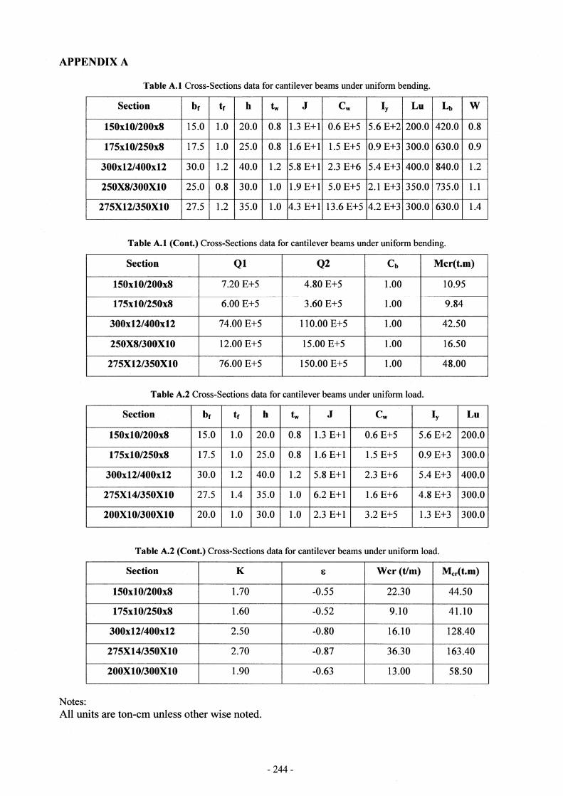
APPENDIX A
Table A.1 Cross-Sections data for cantilever beams under uniform bending.
Table A.1 (Cont.) Cross-Sections data for cantilever beams under uniform bending.
Table A.2 Cross-Sections data for cantilever beams under uniform load.
Table A.2 (Cont.) Cross-Sections data for cantilever beams under uniform load.
Notes:
All units are ton-cm unless other wise noted.
― 244―

Table A.3 Cross-Sections data for cantilever beams under end concentrated load.
Table A.3 (Cont.) Cross-Sections data for cantilever beams under end concentratedload.
Notes:
All units are ton-cm unless other wise noted.
APPENDIX B
Fig. B1 Model of regression analysis output.
Fig. B2 Regression statistics for uniform moment, uniform load, and end concentrated load respectively.
―245―

REFERENCES
1) Chen, W. F., and Lui, E.M., "structural stability Theory and Implementation", Elsevier Science Publishing Co, Inc, 1978.
2) Nethercot, D. A., and Rocky, K. C. A unified approach to the elastic lateral buckling of beams. The structural Engineer. Vol. 49, No. 7, P. P. 321- 330, July 1971.
3) Ojalvo, M. and Chambers, R. S., "Effect of Warping Restraints on I-beams buckling," J. Struct. Div., ASCE, 103(12), P. P. 2351-2360, 1977.
4) Hotchkiss J., "Torsion of Rolled Steel Sections in Building Structures", AISC, January 1996.
5) Kirpy, P. A., and Nethercot, D. A. Design for structural stability. Constrado Monographs, Granada Publishing, Suffok, UK, 1979.
6) Murtha-Smith, E., "Cross Stiffeners for Beams in Torsion", ASCE, July 1996.
7) Valentino, J., and Trahair, N., "Torsional Restraint Against Elastic Lateral Buckling", ASCE, October 1998.
8) Szewczak, R. M., Smith, E. A., and Dewolf, J. T. "Beams With Torsional Stiffeners," J. Struct. Engrg., ASCE, 109(7), P. P 1635- 1647, 1983.
9) Takabatake, H. "Lateral Buckling of I-Beams With Web Stiffeners and Batten Plates," Int. J. of Solids. Struct, 24(10), P. P. 1003- 1019, 1988.
10) Ojalvo, M., Discussion of "Torsional Stiffening of I-girder webs," by C. D. Heins and R. A. Potocko, J. Struct. Div., ASCE, 106(4), P. 939, 1980.
11) Bazant, Z. P., Cedolin L., "Stability of Structures, Elastic, Inelastic, Fracture, and Damage Theories", 1991.
12) Machaly, El-Sayed Bahaa, "Behavior, Analysis and Design of Structural Steel elements", 2001.
13) Trahair, N.S., "Flexural-Torsional Buckling of Structures", 2000.
14) Cosmos/M, User' s Guide Manual, Version 2. 6, Structural Research and Analysis Corporation (SRAC), 1997.
15) Neter J., Wasserman W., Kutner M., "Applied Linear Statistical Models", Third Edition, 1990.
16) Trahair, N.S., Lateral buckling of over hanging beams, in Instability and Plastic Collapse of Steel Structures, (ed. L.J. Morris), Granada, London, pp.503- 18, 1983.
17) Morrison, T., "Lateral Buckling of Constrained Beams", ASCE, March 1972.
18) Siev A., "Torsion in Open Sections of Narrow Rectangles", AISC, January 1996.
19) Timoshenko, S. P., and Gere, J. M. Theory of Elastic Stability. Second edition. Engineering Societies Monographs, McGraw-Hill, NY, p. 223, 1961.
SYMBOLS
a Stiffeners spacing, (cm). Af Area of compression flange (cm2).bf Compression flange width, (cm).
Cb Coefficient depending on the type of load and support conditions.
Cw =Iw Warping torsion constant, (cm6). d Beam total depth, (cm). E Modulus of elasticity, 2100 t/cm2f1 Inverse of stiffeners number.
f2 Beam aspect ratio.
f3 Ratio between stiffener torsion and
bending rigidity.
G Shear modulus, (t/cm2)h Web height, (cm).
Iy Moment of inertia of the cross section about the minor axis of the beam, (cm4).
J Uniform torsion constant, (cm4).L Beam span, (cm).Mcr without stiffeners
Critical moment for the case of beam without stiffeners, (t.m).
Mcr Critical momcnt, (t.m). Pcr Critical concentrated load, (ton). Q1 Term that represents the uniform Torsion
resistance, (t2.cm2). Q2 Term that represents the non uniform
(warping) torsion resistance, (t2.cm2). Q end concentrated load, (ton). q uniformly distributed load, (t/m). S The magnification in the critical Moment.
tf Flange thickness, (cm).
ts Stiffener thickness, (cm).
tW Web thickness, (cm).
Wcr Critical uniform load, (ton).yQ Load height, (cm).ε A dimensionless load height parameter.
φL Beam twisting angle, (radian).η Factor which represents the magnification
in beam uniform torsion resistance that
resulted in using vertical web stiffeners.
β Factor which represents the magnification
in cantilever beam resistance for lateral
torsional buckling that resulted in using
vertical web stiffeners.
α Factor, which represents the magnification in beam non uniform (warping) torsion resistance that resulted in using vertical web stiffeners.
(Accepted April 16, 2004)
―246―