Embed Size (px)
Citation preview

Software and Systems Engineering for Embedded Systems
VO Embedded Systems Engineering
Armin WasicekWS 2010/11

Outline
• What is Software Engineering?• Processes Models • Standards and Reference Architectures• Software Engineering Disciplines RequirementsDesignTesting
Embedded Systems Engineering VO 2

Software Crises
"To put it quite bluntly: as long as there were no machines, programming was no problem at all; when we had a few weak computers, programming became a mild problem, and now we have gigantic computers, programming has become an equally gigantic problem." [Edsger Dijkstra]
Manifestation • Projects running over‐budget and over‐time• Software was of low quality and code difficult to maintain • Unmanageable projects
The term software engineering was popularized after 1968,during the 1968 NATO Software Engineering Conference
Embedded Systems Engineering VO 3

Software Engineering is …
(1) the application of a systematic, disciplined, quantifiable approach to the development, operation, and maintenance of software, that is, the application of engineering to software," and
(2) the study of approaches as in (1).from the IEEE Standard 610.12
Embedded Systems Engineering VO 4

Incremental Process Models
• Waterfall Model• V‐Model• ROPES Spiral Lifecycle• Rational Unified Process• Hardware/Software Codesign
Embedded Systems Engineering VO 5
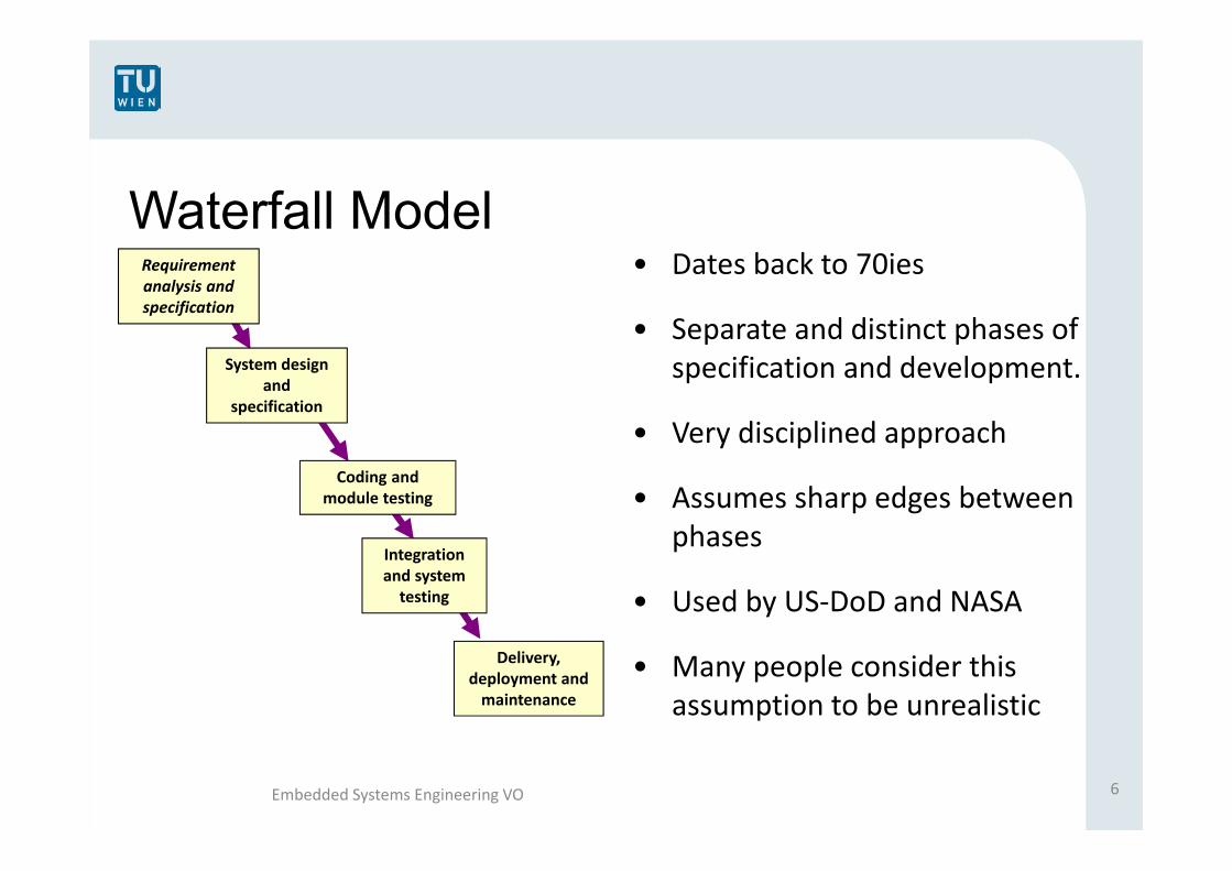
Waterfall Model
Delivery, deployment and maintenance
Integration and system testing
Coding and module testing
System design and
specification
Requirementanalysis andspecification
• Dates back to 70ies
• Separate and distinct phases of specification and development.
• Very disciplined approach
• Assumes sharp edges between phases
• Used by US‐DoD and NASA
• Many people consider this assumption to be unrealistic
Embedded Systems Engineering VO 6

V Model
Verification
Verificat.
Verification
Validation
Architecture design
Code
Acceptance test
System test
Integration Test
Unit Test
Detailed Design
Specification
Requirements
Embedded Systems Engineering VO 7
Zeit
Detailgrad

Spiral Model (e.g., ROPES)• The result of every spiral
cycle is a prototype
• Each prototype should have a mission statement
• Iterative prototypes are constructed by modifying the previous prototype
• Incremental development(Taken from Bruce Powel Douglas)
Embedded Systems Engineering VO 8

Embedded Systems Engineering VO 9
Manifesto:
• Individuals and interactionsover processes and tools
• Working softwareover comprehensive documentation
• Customer collaborationover contract negotiation
• Responding to changeover following a plan

Identified Failure Causes in SW Projects• Ad hoc requirements management• Ambiguous and imprecise communication • Brittle architecture • Overwhelming complexity • Undetected inconsistencies in requirements, designs, and
implementations • Insufficient testing • Subjective assessment of project status • Failure to attack risks • Uncontrolled change propagation • Insufficient automation
Embedded Systems Engineering VO 10

Principles and Best Practices
• Develop software iteratively• Manage requirements• Use component based architecture• Visually model software• Verify software quality• Control changes to software
Embedded Systems Engineering VO 11

Hardware/Software Co-Design
Traditional Design• A specific hardware platform is chosen• Software is designed for that platform• Hardware and software are optimized independently
HW/SW Co‐Design• The whole system is specified in an platform independent way• Semi‐automatic HW/SW partitioning w.r.t. system functions • Semi‐automatic synthesis and code generation• HW and SW are optimized together • Optimized cost/value ratio
Embedded Systems Engineering VO 12

Exemplary Standards in the Automotive domain
• OSEK/VDX Standard• AUTOSAR• MISRA C
Embedded Systems Engineering VO 13

OSEK/VDX - Standard
“Offene Systeme und deren Schnittstellen für die Elektronik im Kraftfahrzeug”
Founded in 1993 as a joint project in the German automotive industry • Project partners: BMW, Bosch, DaimlerChrysler, Opel, Siemens, VW and
University of Karlsruhe, • In 1994 the two French companies (PSA and Renault) joined introducing
their VDX‐approach (Vehicle Distributed eXecutive)
The open architecture comprises three areas:• OSEK‐COM (data exchange within and between control units)• OSEK‐OS (real‐time execution of ECU software and base for the other
OSEK/VDX modules)• OSEK‐NM (Network Management, Configuration determination and
monitoring) Embedded Systems Engineering VO 14

AUTOSAR - Technical Overview
� Technical goals:• Modularity• Scalability• Transferability• Re‐Usability
� Achieved by standardized interfaces• AUTOSAR software components (encapsulate applications)• Virtual Functional Bus – VFB (sum of all communication mechanisms
provided on an abstract, i.e. technology independent, level.) • Runtime Environment (implements the VFB functionality on a specific
ECU)
(Taken from www.autosar.org)
“AUTomotive Open System Architecture” • Open standard for automotive
E/E architecture
Embedded Systems Engineering VO 15

Coding Guidelines - MISRA C“Motor Industry Software Reliability Association” • Guidelines for the use of the C language in critical systems• Used in automotive, rail, aerospace, military and medical
sector• More than 100 rules for safe programming to avoid runtime
errors and misunderstanding among programmers• E.g.: if (i = a) { /* instruction */ }
is forbidden. Could be confused with if(i == a) {/* instruction */ }
• In the automotive sector these guidelines are generally mandatory
Embedded Systems Engineering VO 16

Software Engineering Disciplines
• Requirements Engineering• Design• Construction• Testing• Maintenance• Quality Assessment • Documentation
Embedded Systems Engineering VO 17

Requirements Engineering
• Establishes the services that are required from a system by the costumer and the constraints under which a system has to be developed
• The result of this process is a requirement specification document, which can serve as a contract between the costumer and the developer
• Often used as a binding contract between distributor and customer
Embedded Systems Engineering VO 18

Functional vs. Non-Functional Requirement
• Functional Requirement• Specifies a specific behavior of a system• Based on use cases
• Non-functional Requirement• Specifies criteria that can be used to judge the operation
of a system • Constraints on standards or the development process
• Are temporal requirements functional or non-functional in embedded systems?
Embedded Systems Engineering VO 19

Good Requirements
Embedded Systems Engineering VO 20
Attribute Description
Concise The requirement addresses one and only one thing.
Unambiguous The requirement is concisely stated without recourse to technical jargon, acronyms, or other esoteric verbiage.
Necessary The absence of the Req. will result in a deficiency that cannot be tolerated.
Consistent The requirement does not contradict any other requirement.
Complete The Req. is fully stated in one place with no missing information.
Traceable The Req. Can be traced throughout the entire developmentprocess.
Verifiable Fulfillment of Req. can be vriefied by inspection, demonstration, test or analysis.

Requirement Specification vs. Solution
• Specify abstract enough to avoid predefined solutions
• Specify concrete enough to be able to reach a contract
Embedded Systems Engineering VO 21

Software Engineering Disciplines
• Requirements Engineering• Design• Construction• Testing• Maintenance• Quality Assessment • Documentation
Embedded Systems Engineering VO 22

Unified Modeling Language - UML
• Specification language for object modeling• Officially defined at the Object Management Group
(OMG)• Non-proprietary • General-purpose• Standardized graphical notion • Extendable
Embedded Systems Engineering VO 23

UML Model
• Functional Model• Functionality of the system from the user’s Point of View• e.g. Use Case Diagrams
• Object Model• Structure and substructure of the system (objects,
attributes, operations, associations)• e.g. Class Diagrams
• Dynamic Model• Internal behavior of the system• e.g Sequence Diagrams, Activity Diagrams, State
Machine Diagrams
Embedded Systems Engineering VO 24

Functional Model: Use Case Diagram
• Focuses on the value provided by the system to external entities (human users or other systems)
• Promotes common understanding between the customer/owner/user and the development team
(Taken from www.en.wikipedia.org)
Embedded Systems Engineering VO 25

Object Model: Class Diagram
Describes classes, attributes and relationships
• e.g. generalization
• e.g aggregation
(Taken from www.en.wikipedia.org)
Embedded Systems Engineering VO 26

Dynamic Model: State Diagram
• Filled circle, denoting start• Hollow circle, denoting stop• Rectangle, denoting state
Name Activity
• Arrow, denoting transition [ ] denoting condition
(Taken from www.en.wikipedia.org)
Embedded Systems Engineering VO 27

Definition of SW Testing
Testing can show the presence of bugs, but never their absence.
[Dijkstra (1972)]
Testing is the process of executing a program or system with the intent of finding errors.
[Myers 79] The art of software testing
Embedded Systems Engineering VO 28

29
Validation vs. Verification
• Validation – are we building the right system?
• Verification – are we building the system right?• Does the system/software meets
its specification
Testing Review Formal verification
Embedded Systems Engineering VO

Black-Box testing
• Functional focus Test data are derived by the functional specification
• Specification driven, examines system from the services it provides via its interface - “Exhaustive input testing” Tester considers the SW/system as a black box, visible are only: Inputs,
Outputs and Specification
• No implementation details can be used to build test-cases (they are not known)
• Remaining problem (is the Specification correct?) Approx. 30% of bugs due to incorrect Specification
input output
Embedded Systems Engineering VO 30

Black-Box / Functional testing
• Boundary values• use inputs that represent “boundary” values within a
particular range e.g., for unsigned char, use 0 and 256
• Exception testing • Test what should trigger a failure mode or an exception
mode • Error guessing: test based on prior experience
Embedded Systems Engineering VO 31

White-Box testing
• Structural focus - unit and system testing Test data are driven based on knowledge of program
design/implementation
• Performed in parallel with code development Can be started the first day of development
• Goal: exercise paths and states within the object „Exhaustive path testing“
// Update the CRC for transmitted and received data using
// the CCITT 16bit algorithm (X^16 + X^12 + X^5 + 1).
unsigned char ser_data;
static unsigned int crc;
crc = (unsigned char)(crc >> 8) | (crc << 8);
crc ^= ser_data;
crc ^= (unsigned char)(crc & 0xff) >> 4;
crc ^= (crc << 8) << 4;
input output
Embedded Systems Engineering VO 32

White-Box testing
• Code coverage• Each code line shall be executed at least once during the testing
• Branch coverage• DC - Decision coverage
All possible decisions • MCDC - modified condition decision coverage
All possible variants of the decision
if (A || B) {dosomething1} else {dosomething2}
Embedded Systems Engineering VO 33

When do we stop testing?
Is a trade-off between budget/time and quality
Pessimistic:• whenever some, or any of the allocated resources - time,
budget are exhausted (unfortunately most often used).• test cases are exhausted
Optimistic:• when either reliability meets the requirement, or the
benefit from continuing testing cannot justify the testing cost.
Embedded Systems Engineering VO 34

ENDE
Danke für die Aufmerksamkeit!
Embedded Systems Engineering VO 35