Embed Size (px)
Citation preview
PM-1.1-03 Rev B February 2005
Section15 REV B ����������������
���������� ������� ����������� ����������� ������� ����������� ����������� ������� ����������� ����������� ������� ����������� � ����
The GOES N-P spacecraft support ground system (SSGS)
• Generates spacecraft commands for uplink
• Processes telemetry downlinks, instrument data downlinks, and multi-use data link (MDL) data
• Generates the GOES variable (GVAR) data uplink to the spacecraft
• Determines the spacecraft orbit and attitude using star look, range, and landmark data
• Provides stationkeeping maneuver planning tools
• Monitors GVAR data broadcast quality.
The SSGS comprises seven elements:
• N-Q telemetry acquisition and command transmission system (NTACTS)
• GOES N-Q telemetry and command system (GTACS)
• Orbit and attitude tracking system (OATS)
• MDL receive system and server (MRS&S)
• Dynamic interaction diagnostic (DID)
• Sensor processing system (SPS)
• Product monitor (PM).
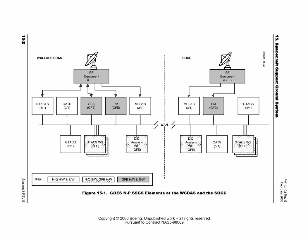
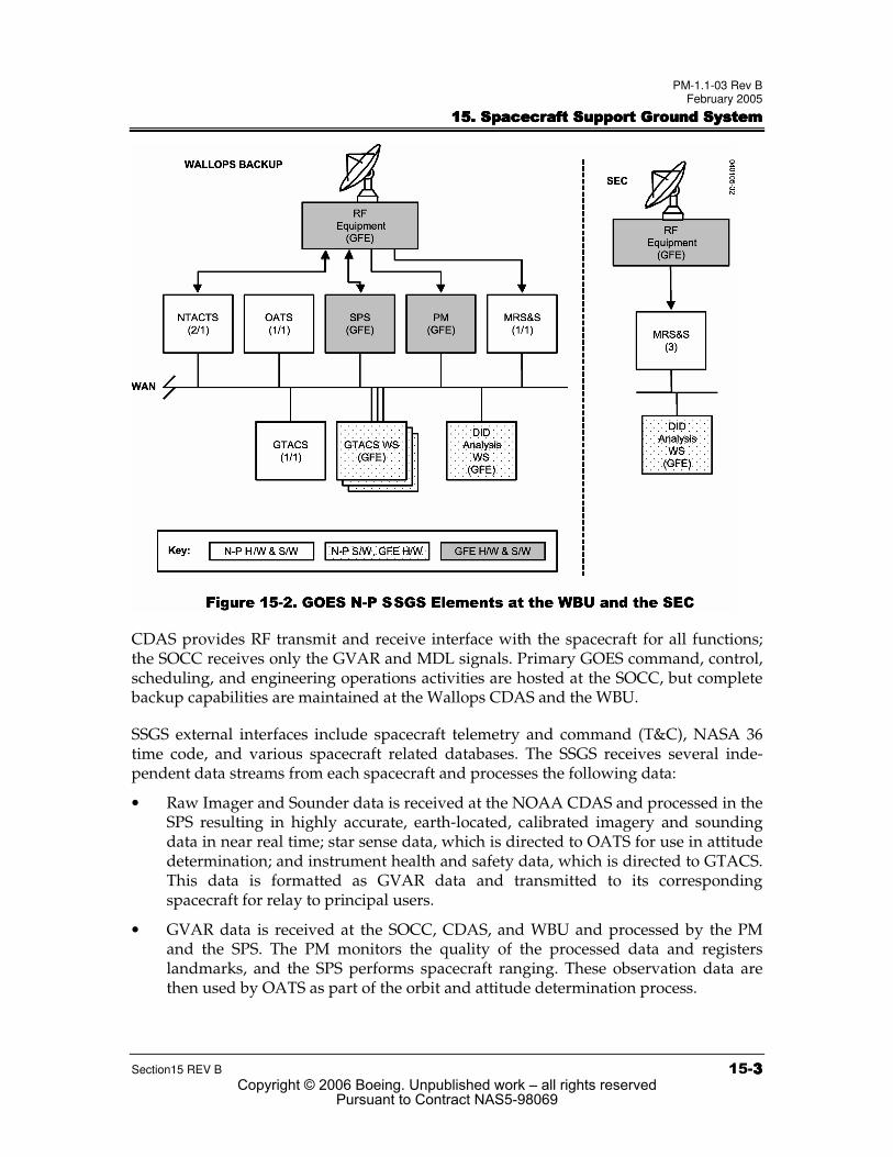
As shown in Figures 15-1 and 15-2, the GOES SSGS equipment resides at National Oceanic and Atmospheric Administration (NOAA) facilities at the locations below:
• Satellite Operations Control Center (SOCC) in Suitland, MD
• Wallops Command and Data Acquisition Station (CDAS) in Wallops, VA
• Wallops Backup (WBU) at the Goddard Space Flight Center (GSFC) in Greenbelt, MD, capable of supporting one GOES satellite
• Space Environmental Center (SEC) in Boulder, CO.
Copyright © 2006 Boeing. Unpublished work – all rights reservedPursuant to Contract NAS5-98069
PM
-1.1-03 Rev B
February 2005
���������� ��
����� ��
��������� �
���������� ��
����� ��
��������� �
���������� ��
����� ��
��������� �
���������� ��
����� ��
��������� ��
������ ���� �
Section15 R
EV
B
RFEquipment
(GFE)
NTACTS(5/1)
SPS(GFE)
OATS(2/1)
PM(GFE)
DIDAnalysis
WS(GFE)
WALLOPS CDAS
GTACS WS(GFE)
GTACS(2/1)
RFEquipment
(GFE)
GTACS(4/1)
OATS(5/1)
PM(GFE)
DIDAnalysis
WS(GFE)
SOCC
GTACS WS(GFE)
MRS&S(3/1)
Key: N-Q H/W & S/W N-Q S/W, GFE H/W GFE H/W & S/W
MRS&S(3/1)
000536_31.ppt
WAN
������������������������������ � ��� � �� !"#������ ����!!�
Copyright © 2006 Boeing. Unpublished work – all rights reservedPursuant to Contract NAS5-98069
PM-1.1-03 Rev B February 2005
���������� ������� ����������� ����������� ������� ����������� ����������� ������� ����������� ����������� ������� ����������� � �
Section15 REV B ���$$$$
CDAS provides RF transmit and receive interface with the spacecraft for all functions; the SOCC receives only the GVAR and MDL signals. Primary GOES command, control, scheduling, and engineering operations activities are hosted at the SOCC, but complete backup capabilities are maintained at the Wallops CDAS and the WBU.
SSGS external interfaces include spacecraft telemetry and command (T&C), NASA 36 time code, and various spacecraft related databases. The SSGS receives several inde-pendent data streams from each spacecraft and processes the following data:
• Raw Imager and Sounder data is received at the NOAA CDAS and processed in the SPS resulting in highly accurate, earth-located, calibrated imagery and sounding data in near real time; star sense data, which is directed to OATS for use in attitude determination; and instrument health and safety data, which is directed to GTACS. This data is formatted as GVAR data and transmitted to its corresponding spacecraft for relay to principal users.
• GVAR data is received at the SOCC, CDAS, and WBU and processed by the PM and the SPS. The PM monitors the quality of the processed data and registers landmarks, and the SPS performs spacecraft ranging. These observation data are then used by OATS as part of the orbit and attitude determination process.
Copyright © 2006 Boeing. Unpublished work – all rights reservedPursuant to Contract NAS5-98069
PM-1.1-03 Rev B February 2005
���������� ������� ����������� ����������� ������� ����������� ����������� ������� ����������� ����������� ������� ����������� � �
���%%%%���� Section15 REV B
• MDL data is received at the Wallops CDAS, SOCC, WBU, and SEC and processed by the MRS&S. This stream includes Imager and Sounder servo error data, Imager image motion compensation (IMC) data, angular velocity sensor data, Solar X-ray Imager (SXI) and, potentially, instrument of opportunity (IOO) instrument data, and spacecraft spacecraft pulse code modulated (PCM) telemetry. The MRS&S makes this data available to the DID for diagnosing dynamic interactions among the instruments and the spacecraft.
• Two streams of PCM data are received at the Wallops CDAS and WBU. The NTACTS provides bit and frame synchronization and passes the data on to GTACS for further processing. These streams contain spacecraft health and safety data used in monitoring spacecraft commanding performed on the ground or from stored commands on the spacecraft. The SEC derives SXI and space environment monitor (SEM) instrument data from the MDL stream for use in solar environment forecasting.
Spacecraft commanding is generated within GTACS. Bit-level, encrypted commands are transferred from GTACS to NTACTS, which provides the interface to the Government furnished equipment (GFE) RF system for uplink to the spacecraft.
The SOCC, the Wallops CDAS, and the WBU LANs are interconnected via routers at each site, which, in turn, are interconnected by landline circuits plus a leased 56 kbps domestic satellite circuit. Operations voice circuits are also provided via the landlines. The interconnectivity allows the exchange of both spacecraft operations data and status data among SSGS elements. The data exchange between GTACS and NTACTS uses the TCP/IP socket protocol.
��������&&&&�'�� ���#(���� ��������!�� � ����'����� ���������� � ��'�� ���#(���� ��������!�� � ����'����� ���������� � ��'�� ���#(���� ��������!�� � ����'����� ���������� � ��'�� ���#(���� ��������!�� � ����'����� ���������� � �
)�'#!'�*)�'#!'�*)�'#!'�*)�'#!'�*����NTACTS provides an interface between GTACS and the GFE RF systems at the Wallops CDAS and WBU for PCM telemetry receipt and spacecraft command transmission. The function of the NTACTS is similar to that of the TACTS in the GOES I-M SSGS; that is, supplying the GOES N-P ground segment of the space-to-ground and ground-to-space communications link. Each NTACTS services a single GOES N-P spacecraft and is able to receive two PCM telemetry streams as IF signals. NTACTS bit synchronizes, frame synchronizes, time tags, and formats the minor frame data for each stream for transmis-sion to GTACS. NTACTS receives commands from GTACS in a form ready to uplink (encryption is already applied) and modulates an IF command signal that is passed to the GFE ground station RF equipment for transmission to the spacecraft. In support of the command link, NTACTS sweeps the carrier to establish carrier lock with the space-craft at initiation of contact and transmits an idle pattern between commands to main-tain lock. Each NTACTS can send telemetry data to multiple GTACS to provide receipt redundancy. However, NTACTS can establish a commanding connection to only one GTACS at a time. NTACTS also sends processing status data to GTACS.
Copyright © 2006 Boeing. Unpublished work – all rights reservedPursuant to Contract NAS5-98069
PM-1.1-03 Rev B February 2005
���������� ������� ����������� ����������� ������� ����������� ����������� ������� ����������� ����������� ������� ����������� � �
Section15 REV B �������
There are five NTACTS at the Wallops CDAS and two at the WBU. NTACTS communicates with GTACS via TCP/IP sockets.
����������������������������&&&&�'�� �������!�� � ������� � �)�'#!�*�'�� �������!�� � ������� � �)�'#!�*�'�� �������!�� � ������� � �)�'#!�*�'�� �������!�� � ������� � �)�'#!�*����GTACS performs tasks similar to those performed by the GOES I-M telemetry and command system (GIMTACS) for the GOES N-P using a distributed system of servers and user workstations located at the SOCC, Wallops CDAS, and WBU. GTACS proc-esses all real time and nonreal time spacecraft telemetry data, generates spacecraft com-mands, provides command schedule generation and upload capabilities, and performs ground system monitoring and control functions.
GTACS consists of four servers at the SOCC, two servers at the Wallops CDAS, and one server at the WBU. GTACS servers receive data streams from NTACTS (raw PCM minor frames), MRS&S (SXI housekeeping data), and SPS (Imager and Sounder housekeeping data) and process status information from each of these elements. The servers archive the raw data, decommutate and convert values to engineering units and check database limits, and provide the resulting parameter values to other processes such as user dis-play. Each server can furnish these services concurrently for multiple spacecraft; the entire GTACS element can support up to eight spacecraft (including real and simulated spacecraft). The GTACS servers also support command generation and real time sched-ule execution (if schedule commanding is from the ground) and monitor the execution of onboard schedules. Binary commands nominally are encrypted using commercial encryption devices before transmission to NTACTS for uplink.
More than one server can be configured to receive data from a spacecraft, providing redundancy in case of a server or network failure. If multiple servers are configured to support one spacecraft, one server is configured as prime, with the other servers config-ured as backups. Only the prime server can generate spacecraft commands, and only one user on the prime has authority to issue commands. In a redundant configuration, servers at the CDAS and SOCC can support the same spacecraft. Nominally, the server at the CDAS will be configured as prime, enabling schedule related processing to con-tinue uninterrupted in case of network failure between the SOCC and CDAS. Users at the SOCC can connect to either the CDAS or SOCC server for data service. Users at the CDAS will connect only to collocated servers.
Users interact with the system on GFE NT Intel-based workstations. A pool of GFE workstations can be used to support different missions and different aspects of those missions. The assigned user privileges and the corresponding software applications cur-rently in use determine the functions which can be performed on that workstation. GTACS does not provide backward compatibility support for other missions.
Copyright © 2006 Boeing. Unpublished work – all rights reservedPursuant to Contract NAS5-98069
PM-1.1-03 Rev B February 2005
���������� ������� ����������� ����������� ������� ����������� ����������� ������� ����������� ����������� ������� ����������� � �
���++++���� Section15 REV B
These workstations support three categories of user operations. First, a workstation can be configured to provide real time T&C operations for a specific spacecraft using data received from a GTACS server. Telemetry and system data points can be monitored using parameter text displays and plots. Users can also create and run procedures that make use of telemetry or other GTACS element data. Users can also monitor the status of SSGS elements and configure aspects of these elements.
Second, a workstation can be configured to analyze nonreal time data. Using this capability, a user can perform trending analysis, recall archived data, export data, and use additional analysis tools not applicable to real time data.
Third, a workstation can be configured to generate schedules. In this mode, a user can start with schedule building blocks and create a set of schedules for daily operations to be commanded either from the ground or from the spacecraft. These schedules are then distributed to other functions within GTACS either for execution or upload to the space-craft. Schedules are nominally generated at the SOCC.
The GTACS support available at the WBU is similar to that at the Wallops CDAS, but its support capabilities are reduced due to its lower equipment count, principally only one antenna. Workstations at the SOCC can be configured to use the WBU server for real time T&C service, as can workstations within the WBU facility. However, workstations at the Wallops CDAS or the WBU will not nominally use a server at the other facility.
��,� �����# � ���'��-������� � �)�#'�*��,� �����# � ���'��-������� � �)�#'�*��,� �����# � ���'��-������� � �)�#'�*��,� �����# � ���'��-������� � �)�#'�*����The OATS performs three major functions in support of mission operations using telemetry and status data obtained from GTACS, star sense and range data provided by the SPSs, and landmark and IMC data obtained from the PMs. The primary function is to provide daily computational support for implementing the orbit and attitude deter-mination (OAD) and image navigation and registration (INR) processes. This support consists of a closed-loop sequence that:
• Ingests star, range, and landmark observations
• Determines spacecraft orbit and Imager and Sounder attitudes
• Determines station radio frequency interference (RFI), and solar and lunar intrusions into the Imager and Sounder
• Predicts eclipses
• Computes image motion compensation
• Determines star observation coordinates.
This daily support is performed both for normal operations and special operations such as during eclipses and yaw-flip maneuvers.
Copyright © 2006 Boeing. Unpublished work – all rights reservedPursuant to Contract NAS5-98069
PM-1.1-03 Rev B February 2005
���������� ������� ����������� ����������� ������� ����������� ����������� ������� ����������� ����������� ������� ����������� � �
Section15 REV B ���....
The second major function of OATS is to plan, generate command data, and evaluate maneuvers such as daily momentum dumping, periodic stationkeeping, and reposi-tioning maneuvers. The evaluation includes estimates of the remaining onboard pro-pellant and calibration of the propulsion system.
Finally, OATS requests, accepts, and processes telemetry data such as evaluating thruster firing data and attitude control electronics (ACE) data to verify and calibrate IMC, stationkeeping, and reacquisition support. The OATS also supports the GTACS command-level schedule generation process, generating instrument commands for image frame coordinates and definitions and scheduling star looks.
OATS generates output such as:
• Orbit and Imager/Sounder attitude coefficients for the SPS
• IMC coefficients uplinked to the spacecraft via GTACS
• Star view command data to support Imager and Sounder star sense and sequence operation
• Maneuver planning information and spacecraft stationkeeping command data
• Commands required for daily reaction wheel momentum dumping
• Estimates of onboard propellant remaining
• Propulsion calibration parameters
• Orbit and station events prediction
• Sensor intrusion predictions
• Star tracker intrusion predictions during yaw-flip maneuvers
• Scan frame coordinates conversion
• IMC calibration factors
• Transformation between the IMC set J2000 and the star catalog true-of-date coordinates.
OATS functions are performed on primary and backup systems at the SOCC (five OATS total), with additional backup systems installed at the Wallops CDAS (two OATS total) and the WBU (one OATS). The backup systems are maintained with the most current data so that transfer to the backup OATS (either forced due to primary failure or orderly) may occur with little operational interruption. OATS also archives data for later analysis.
Copyright © 2006 Boeing. Unpublished work – all rights reservedPursuant to Contract NAS5-98069
PM-1.1-03 Rev B February 2005
���������� ������� ����������� ����������� ������� ����������� ����������� ������� ����������� ����������� ������� ����������� � �
���////���� Section15 REV B
OATS exchanges data with other SSGS elements. OATS communicates with GTACS and each other over an Ethernet LAN. OATS provides orbit and attitude related data to GTACS for schedule creation and for maneuver commanding. GTACS provides atti-tude-related data to OATS, as well as star sense data from SPS with acquisition times added. OATS also exchanges data with the PM and SPS via a gateway that handles protocol translation. These messages include data for spacecraft ranging, landmarks and image correction calibration data.
0"1�2�3���� � �������3���)02�4�*0"1�2�3���� � �������3���)02�4�*0"1�2�3���� � �������3���)02�4�*0"1�2�3���� � �������3���)02�4�*����The MRS&S provides data ingest, archive, and data service to the DID for the MDL telemetry stream. The MDL stream contains data that can be used in analyzing space-craft structure dynamic interactions in the DID. The data included in the MDL stream include Imager and Sounder servo error data, Imager IMC data, and angular displacement sensor data. These data complement instrument telemetry data received by the SPS. In addition to these data, the MDL telemetry stream also has four other telemetry streams embedded in it: two PCM telemetry streams (replications of the independently downlinked PCM telemetry streams), the SXI telemetry stream, and, potentially, the IOO telemetry streams. All of these data streams are packetized in MDL packets (not CCSDS) and multiplexed onto the MDL downlink.
Each MRS&S services one spacecraft. The MRS&S has an IF interface to the GFE RF system from which it receives the MDL telemetry stream. The MRS&S demodulates and bit synchronizes the MDL stream. The MRS&S then frame synchronizes this data to identify the MDL frames and packets. The MDL-specific dynamics data can be decom-mutated directly from these packets. The MRS&S demultiplexes these four telemetry streams back into four independent bit streams and then frame synchronizes each stream independently. The MRS&S does not decommutate any data from the SXI or IOO streams. The MRS&S decommutates a limited number of data points in the PCM streams required for analysis by the DID.
The MRS&S provides data to the DID via TCP/IP sockets. The DID requests specific MDL telemetry data points from the MRS&S either for real time service or for a specific time range contained in the MRS&S archive. The MRS&S sends data from the embedded SXI telemetry stream to the SXI analysis workstation via TCP/IP sockets. The MRS&S supplies SXI health and safety engineering data to GTACS. GTACS can also request the PCM streams from the MRS&S, providing an alternate path not requiring the space-craft’s T&C RF transmitters.
The SOCC and the Wallops CDAS each have three copies of the MRS&S, while the WBU has one copy. The Space Environment Center (SEC) in Boulder, Colorado, also has three copies of the MRS&S, which are used for receiving the SXI and PCM data streams, which contain the SEM instrument data.
Copyright © 2006 Boeing. Unpublished work – all rights reservedPursuant to Contract NAS5-98069
PM-1.1-03 Rev B February 2005
���������� ������� ����������� ����������� ������� ����������� ����������� ������� ����������� ����������� ������� ����������� � �
Section15 REV B ���5555
"���� ��6� �� ����"������ ��)"6"*"���� ��6� �� ����"������ ��)"6"*"���� ��6� �� ����"������ ��)"6"*"���� ��6� �� ����"������ ��)"6"*����The DID provides data selection, plotting, and analysis tools, using data in the MDL telemetry stream to measure interaction between mechanical motion events (such as momentum/reaction wheel, solar array drive assembly, and Imager/Sounder mirror motion). The tools are used during initial on-orbit checkout to identify dynamic effects that produce excessive interaction and to support the development of operational sce-narios that avoid or minimize such interaction. Diagnostic telemetry can be used at any time during subsequent spacecraft orbital operations for the same purpose. The MRS&S sends data to the DID via a TCP/IP socket connection. Using the DID data selection interface, the user can request parameters to be analyzed and that the MRS&S supply data for a specified time span or as it is received in real time.
The SOCC will have two copies of the DID, the Wallops CDAS and WBU will each have two copies, and the SEC will have one. A DID can support one spacecraft at a time. DID workstations are GFE. The DID workstations are also used to support functions other than the GOES N-P DID function, such as SXI analysis or GOES N-P DID analysis. The GOES N-P DID function provides similar capabilities to those provided by the GOES I-M DID, but is not backward compatible.
��������������������������������������������������������������� � ��)���*��� � ��)���*��� � ��)���*��� � ��)���*����The SPSs perform all functions associated with processing Imager and Sounder instrument data from the GOES I-M and N-P spacecraft, one spacecraft per SPS. This element is GFE to GOES N-P. This description is included for context. Functions pro-vided by the SPS include data ingest, including frame synchronization, decommutation by channel, detector scan alignment, and alternate scan line reversal; visible image nor-malization; IR radiometric calibration; earth location and Imager gridding annotation; reformatting of instrument data into the GVAR format; computation of Imager and Sounder space look, blackbody, electronic calibration and instrument telemetry statistics for inclusion in GVAR data stream; binary phase shift keyed (BPSK) modulation of the GVAR data stream; and spacecraft ranging. The modulated GVAR signal is passed to the GOES RF system for uplink to the spacecraft.
To support the orbit and attitude determination function of the OATS subsystem, the SPS also performs spacecraft range measurements using the GVAR data stream round trip propagation time, performs star crossing event measurements by processing Imager and Sounder star view data, and extracts periodic IMC and servo error data from the sensor data for use in the IMC quality check function performed by OATS.
Further, SPS sends wideband telemetry data, including command register echo information extracted from the Imager and Sounder data streams and scan position to GTACS every two to 10 seconds, as long as valid telemetry is being processed in the SPS. The telemetry message data consists of the latest values received for the telemetry words extracted from the telemetry blocks of the Imager turnaround sequence and telemetry words extracted from the Sounder blocks.
Copyright © 2006 Boeing. Unpublished work – all rights reservedPursuant to Contract NAS5-98069
PM-1.1-03 Rev B February 2005
���������� ������� ����������� ����������� ������� ����������� ����������� ������� ����������� ����������� ������� ����������� � �
����7�7�7�7���� Section15 REV B
There are four SPSs at the Wallops CDAS, one to support the GOES East spacecraft, one for the GOES West spacecraft, and two spares. One SPS is planned for the WBU. The spares typically provide hot backups, but can also be used to support testing or third spacecraft operations on a limited basis. The SPSs are interconnected via an Ethernet LAN and communicate with GTACS and OATS via an X.25 connection to a gateway at the CDAS. The SPSs send messages containing ranging and star sense data to OATS and instrument housekeeping telemetry and SPS status data to GTACS. SPSs send text mes-sages and data to the PMs via the GVAR broadcast. The PMs send data, such as image alignment correction factors and visible detector normalization (destriping) tables to the SPSs via an X.25 interface.
The SPS subsystem also includes an analyst workstation capability at the SOCC, Wallops CDAS, and WBU through which analysts can access Imager and Sounder SPS archive data maintained at the CDAS for analysis purposes.
����� �0��� ���)�0*����� �0��� ���)�0*����� �0��� ���)�0*����� �0��� ���)�0*����The primary functions of the PMs are to monitor and analyze the quality of the image and nonimage data broadcast in the GVAR data stream, feeding back any required changes to the SPS, and to provide OATS with landmark registration and IMC quality check data in support of INR and attitude determination. This element is GFE to GOES N-P. This description is included for context.
In support of the orbit and attitude determination function, the PM provides landmark identification by storing, displaying, and registering small areas of Imager visible and infrared data (visible Sounder as backup) defined as landmark sectors. Landmark regis-tration is performed by a semiautomatic (an automatic capability is being implemented) correlation of selected landmark sectors to previously stored landmark sectors referred to in landmark correlation chips. Once correlated, landmark measurement data in the form of earth location coordinates are sent to the OATS. The PM also captures the IMC and servo error data included in the GVAR data by the SPS and passes it to OATS, which provides quality checks of the INR function performed onboard the spacecraft.
Nearly identical PMs reside at the SOCC, Wallops CDAS, and WBU, with four, three, and one systems each, respectively. Each PM is capable of supporting one GVAR data stream at a time. One PM is normally assigned to the GOES East broadcast and the other to the GOES West broadcast. Under normal operational circumstances, the PMs at the Wallops CDAS perform only the monitoring function while the PMs at the SOCC per-form the OATS support functions as well as the monitoring functions. In the backup operational configuration, with the OATS resident at the CDAS, the PM roles at the CDAS and SOCC are reversed.
Copyright © 2006 Boeing. Unpublished work – all rights reservedPursuant to Contract NAS5-98069
PM-1.1-03 Rev B February 2005
���������� ������� ����������� ����������� ������� ����������� ����������� ������� ����������� ����������� ������� ����������� � �
Section15 REV B �����������
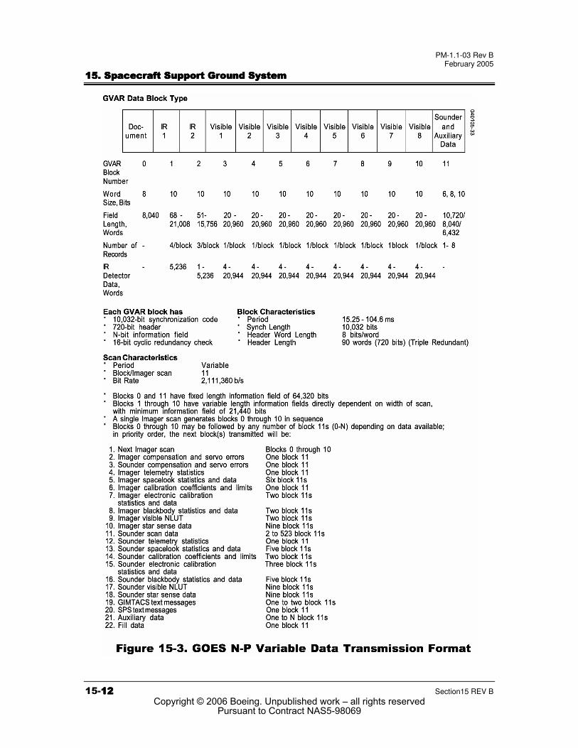
�����8����,��)�8#2*�'����� ����������� � �����8����,��)�8#2*�'����� ����������� � �����8����,��)�8#2*�'����� ����������� � �����8����,��)�8#2*�'����� ����������� � ����The GVAR data transmission format was developed to allow full use of the capabilities of the advanced, three-axis stabilized spacecraft while retaining as much commonality as possible with receiving equipment presently in use from earlier spin-stabilized GOES spacecraft. The GVAR format is based on the operational visible and infrared spin scan radiometer atmospheric sounder (VAS) mode AAA format, which consisted of a repeating sequence of 12 fixed-length equal size blocks. The transmission of these blocks was synchronized with the spin rate of the earlier GOES spacecraft, that is, one complete 12 block sequence per satellite rotation.
The GVAR transmission sequence consists of 12 distinct blocks numbered 0 through 11. Blocks 0 through 10 are transmitted when an Imager scan line is completed. Block 10 is followed by a variable number of block 11s, according to what data are available for transmission (Figure 15-3).
Copyright © 2006 Boeing. Unpublished work – all rights reservedPursuant to Contract NAS5-98069
PM-1.1-03 Rev B February 2005
���������� ������� ����������� ����������� ������� ����������� ����������� ������� ����������� ����������� ������� ����������� � �
��������������� Section15 REV B
Copyright © 2006 Boeing. Unpublished work – all rights reservedPursuant to Contract NAS5-98069
PM-1.1-03 Rev B February 2005
���������� ������� ����������� ����������� ������� ����������� ����������� ������� ����������� ����������� ������� ����������� � �
Section15 REV B ����$�$�$�$
������ ��� ��� �������� ��� ��� �������� ��� ��� �������� ��� ��� ������The GOES N-P spacecraft emulator is a simulation platform that consists of the Applied Dynamics International (ADI) real time station (RTS) and computer workstations. The emulator is contained within a tower unit. It contains various spacecraft components, several compute engines, a Versa-bus Module Eurocard (VME) bus, a 1553 bus, and various software applications. The emulator provides the T&C interface, MDL interface, and Imager and Sounder messages to support SSGS integration and test. In addition, it provides high fidelity models of the spacecraft dynamics, sensors, and actuators, along with orbital and environmental models to support operational procedures development and mission and on-station operation rehearsals.
Copyright © 2006 Boeing. Unpublished work – all rights reservedPursuant to Contract NAS5-98069
PM-1.1-03 Rev B February 2005
���������� ������� ����������� ����������� ������� ����������� ����������� ������� ����������� ����������� ������� ����������� � �
����%�%�%�%���� Section15 REV B
This page left blank.
Copyright © 2006 Boeing. Unpublished work – all rights reservedPursuant to Contract NAS5-98069