Embed Size (px)
Citation preview
GüterwagenDamplok • Steam locomotive Locomotive à vapeur • Parní lokomotiva
Parowóz BR 89
www.tillig.com • www.facebook.com/tilligbahn 364265 / 28.03.2017
112
Art.-Nr. / Item no.
Réf. / Art.-č. / Nr art. 04240
04241
04242
04243
04244
(DE) Das Modell ist mit seinen möglichst maßstäblichen angebauten Einzelteilen und der iligranen Steuerung sehr emp-
indlich. Bitte nehmen Sie das Modell vorsichtig aus der Verpackung, benutzen Sie dazu den Foliestreifen und greifen das Modell nicht mit den Fingern an der Steuerung an. Beim Aus- und Einpacken achten Sie bitte darauf, die am Kessel und Führerhaus angebrachten Details nicht mit dem Foliestreifen oder den Fingern zu beschädigen. Zum Aufgleisen u.a. Angrei-fen nutzen Sie bitte die Flächen der Wasserkästen.Das Modell ist ab Werk mit einem Decoder für DCC und MM Betriebssysteme ausgestattet. Bitte benutzen Sie für den Betrieb konventionelle Gleichstrom Fahrregler (bis 12 V Nennspannung) oder ein entsprechendes Digitalsystem (Gleisspannung 14 … 16V).
(GB) The model is very sensitive with its attached individual parts that are as to scale as possible and the delicate control unit. Please remove the model carefully from the packaging, use the foil strip to this end, and do not grasp the model with your ingers on the control unit. When unpacking and packing, be careful not to damage the details attached to the boiler and cab with the foil strip or your ingers. For rerailing, including engaging it, please use the surfaces of the water boxes.The model is equipped in the factory with a decoder for DCC and MM operating systems. Please use conventional DC current regulators (up to 12 V nominal voltage) or a corresponding digital system (track voltage 14 ... 16 V) for the operation of the set.
(FR) Avec des pièces détachées montées qui respectent le plus possible l’échelle et la commande iligrane, ce modèle est très sensible. Retirez donc le modèle de l’emballage avec précaution., utilisez pour cela la bande de ilm et ne touchez pas le modèle à la commande avec les doigts. Lors de l’emballage et du déballage, veillez à ne pas endommager les détails apposés sur la chaudière et la cabine du conducteur avec la bande de ilm ou les doigts. Pour enrailler ou saisir le modèle, utilisez les surfaces du réservoir à eau.Le modèle est équipé d’un décodeur pour systèmes d’exploitation DCC et MM à l’usine. Pour l’exploitation, utilisez des régu-
lateurs à courant continu conventionnels (jusqu’à une tension nominale de 12 V) ou un système numérique correspondant (tension de rail 14...16V).
(CZ) Jednotlivé díly modelu byly vyrobené s maximální přesností dle měřítka a model má jemné řízení, proto je velmi citlivý. Model vyjměte opatrně z obalu, použijte k tomu pásy fólie a nedotýkejte se prsty řízení modelu. Při vybalování a zabalování dbejte prosím na to, abyste pásem fólie nebo prsty nepoškodili detaily připevněné na kotli a budce strojvůdce. K nasazení na koleje a další manipulaci využijte prosím plochu nádrže na vodu.Model je z výroby vybaven dekodérem pro řídicí systémy DCC a MM. Pro provoz prosím používejte konvenční stejnosměrné ovladače (do 12 V jmenovitého napětí) nebo vhodný digitální systém (stejnosměrné napětí 14 … 16V).
(PL) Model wraz z jego poszczególnymi częściami, możliwie odpowiadającymi skali obiektów rzeczywistych, oraz i-
ligranowym sterownikiem jest bardzo wrażliwy. Model należy ostrożnie wyjąć z opakowania, używając do tego celu paska foliowego i nie dotykając palcami sterownika. Przy odpakowywaniu i pakowaniu należy uważać, aby nie uszkodzić paskiem foliowym lub palcami detali znajdujących się na kotle i budce maszynisty. Stawiając model na szynach lub dotykając go w innym celu, należy używać powierzchni zbiorników wodnych. Model został przez producenta wyposażony w dekoder do systemów DCC i MM. Do eksploatacji należy używać konwencjo-
nalnych regulatorów jazdy prądu stałego (napięcie znamionowe do 12 V) oraz odpowiedniego systemu cyfrowego (napięcia stałe 14 … 16V).
Wichtiger hinWeis • important note • indication importante důležité upozornění • Ważna WskazóWka
0-3
0-3
(GB) Not suitable for young people under the age of 14 due to the small parts that can be removed and swallowed and risk of injury due to
function-related sharp corners and edges. When this product comes to the end of its useful life, you may not dispose of it in the ordinary domestic waste but must take it to your local collection point for recycling electrical and electronic equipment. If you don’t know the location of your nearest disposal centre please ask your retailer or the local council ofice.
(cz) není určené pro děti mladší 14ti let. obsahuje funkční a odnímatelné malé a ostré součásti a hrany. Tento produkt nesmí být na konci svého užívání zlikvidován jako běžný domovní odpad, ale musí být zlikvidován např. ve sběrném dvoře. Prosím, zeptejte se vašeho obchodníka, popř. na svém obecním úřadě o vhodném způsobu likvidace.
(pl) nieodpowiednie dla dzieci poniżej 14 roku życia z uwagi na niebezpieczeństwo połknięcia i zadławienia się drobnymi częściami oraz możliwość skaleczenia się ostrymi końcówkami i krawędziami części funkcyjnych. Produkty oznaczone przekreślonym pojemnikiem po zakończeniu użytkowania nie mogą być usuwane razem z normalnymi odpadami domowymi, lecz muszą być przekazywane do punktu zbierania i recyklingu urządzeń elektrycznych i elektronicznych. Dzięki recyklingowi pomagają Państwo skutecznie chronić środowisko naturalne. Prosimy zwrócić się do specjalistycznego sklepu lub do odpowiedniego urzędu w Państwa okolicy, aby dowiedzieć się, gdzie jest najbliższy punkt recyklingu urządzeń elektrycznych i elektronicznych.
(Fr) ne convient pas aux enfants de moins de 14 ans en raison de pièces pouvant être retirées et avalées et du risque de blessure en raison de coins et de bords vifs dus au fonctionnement. À la in de sa durée de vie, ne pas éliminer ce produit avec les déchets ménagers mais le remettre à un point de collecte pour le recyclage d’appareils électriques et électroniques. Veuillez vous adresser à votre revendeur ou à l’administration communale pour connaître les points d’élimination compétents.
(de) nicht geeignet für kinder unter 14 Jahren wegen abnehmbarer und verschluckbarer kleinteile und Verletzungsgefahr durch funktionsbedingte scharfe ecken und kanten. Dieses Produkt darf am Ende seiner Nutzungsdauer nicht über den normalen Hausmüll entsorgt werden, sondern muss an einem Sammelpunkt für das Recycling von elektrischen und elektronischen Geräten abgegeben werden. Bitte fragen Sie bei Ihrem Händler oder der Gemeindever-waltung nach der zuständigen Entsorgungsstelle.
(DE) Technische Änderungen vorbehalten! Bei Reklamationen wenden Sie sich bitte an Ihren Fachhändler.
(GB) Subject to technical changes! Please contact your dealer if you have any complaints.
(FR) Sous réserve de modiications techniques! Pour toute réclamation, adressez-vous à votre revendeur.(CZ) Technické změny vyhrazeny! Při reklamaci se obraťte na svého obchodníka.(PL) Zastrzega się możliwość zmian technicznych! W przypadku reklamacji prosimy zgłaszać się do specjalistycznego sprzedawcy.
tillig modellbahnen gmbhPromenade 1, 01855 Sebnitz Tel.: +49 (0)35971 / 903-45 • Fax: +49 (0)35971 / 903-19(DE) Hotline Kundendienst • (GB) Hotline customer service • (FR) Services à la clientèle Hotline (CZ) Hotline Zákaznické služby • (PL) Biuro Obsługi Klienta: www.tillig.com/Service_Hotline.html
Die Strecke Heidenau – Altenberg wurde nach ihrer Verwüstung durch ein Hochwasser 1927 wieder als 750mm Schmalspurbahnaufgebaut. Die steigenden Transportleistungen und der zunehmende Autoverkehr verlangten aber nach einer Umspurung auf Normalspurund die Trennung von Straße und Eisenbahn. So begann 1934 der Umbau der Strecke, für die wegen des sehr geringen Mindestradiusesvon 100 m bei großer Steigung neben den neuen Reisezugwagen auch eine neue Lokomotive geschaffen werden musste. Zusätzlichbestand die Forderung, aus der nahen Landeshauptstadt Dresden, Züge durchgehend bis Altenberg fahren zu können. Damit wurde eineHöchstgeschwindigkeit von mindestens 70 km/h gefordert. Weiterer Eckpunkt der Forderungen war ein Achsdruck von 18,5 t. Sie sollte aufeiner Steigung von 1:27 bis 1:30 im Gleisbogen von 140 m Halbmesser einen 175 t-Zug mit 40 km/h befördern. Die 1933 gebaute BR 85 derHöllentalbahn ist dieser Lok äußerlich und leistungsmäßig sehr ähnlich, nur nicht ganz so kurvengängig. Und mit einer Achslast von 20 tkonnte sie für diese Strecke nicht benutzt werden. Während hier die Zylinder auf zwei Achsen antreiben erfolgt der Antrieb der Zylinder beider BR 84 auf eine Achse.Mit den Entwurfsarbeiten wurden 1934 die Firmen BMAG in Wildau und Orenstein & Koppel in Drewitz betraut. Sie führten nacheingehenden theoretischen Unter-suchungen zu zwei Vorschlägen, die in der Achsfolge und in der Kesselbauart übereinstimmten, sichaber im Trieb- und Laufwerk wesentlich voneinander unterschieden. Nach eingehenden Versuchsfahrten wurden die Dreizylinderloks mitSchwarzkopff-Eckard-Gestellen als die geeigneteren befunden und 1937 in Serie von 8 Stück beschafft. Die beiden Zweizylinderloks mitLuttermöller Zahnradantrieb auf den beiden äußeren Kuppelachsen verblieben bis zum Einsatzende der Baureihe weiter im Betrieb. DieAbsicht, diesen Loktyp generell für krümmungs- und steigungsreiche Strecken (z.B. für den Thüringer Wald) zu beschaffen, wurde durchdie Kriegsereignisse nicht realisiert.Bis nach dem Zweiten Weltkrieg waren die Loks auf ihrer Stammstrecke eingesetzt. Da der Bestand an Loks größer als der Bedarf für dieStammstrecke war, erfolgte auch stets ein Einsatz im Dresdner Vorortverkehr. Auch auf der Tharandter Steigung wurden sie alsSchiebeloks eingesetzt. Nach dem Krieg gab es vereinzelt Stationierungen in Gera, Saalfeld, Karl-Marx-Stadt und Riesa, offensichtlichzu Testzwecken. Mit dem Aufkommen des Uranbergbaus im Erzgebirge wurden dort schwere Lokomotiven benötigt. So wurden diemeisten Loks nach Schwarzenberg (später zu Aue gehörig) abgegeben und mussten stets bis an ihre Leistungsgrenzen schwereErzzüge befördern. Dies machte sich natürlich im Verschleiß bemerkbar. Dazu kam der Umstand, dass die Kessel der Loks aus St47Kgefertigt waren, dessen Alterungs-beständigkeit nicht sehr gut war. Die Loks wurden daher bereits bis 1961 ausgemustert. 84 008diente danach noch bis Mitte 1965 als Heizlok im Weichenwerk Karl-Marx-Stadt. Ein Einsatz als Werklok Nr.4 im RAW „Wilhelm Pieck“unterbrach die Heizloktätigkeit zwischen 1961 und 1964. Erwägungen, die Loks zusammen mit der BR 95 einer Rekonstruktion zuunterziehen und auf den Strecken des Thüringer Waldes einzusetzen, wurden fallen gelassen und die Maschinen 1968 zerlegt.
Art.-Nr.: 02190 – BR 84 der DR, Ep. IIIArt.-Nr.: 02191 – BR 84 der DRG, Ep. II
364645-S.115.05.2014
DampflokBR 84
D AS VORB ILD
129,6
D AS M OD ELLDas Modell ist eine maßstäbliche Nachbildung der BR 84. Farbgebung und Dekoration entsprechen dem Vorbild. Die Stromabnahmeerfolgt von allen Treib- und Kuppelradsätzen. Ein 5 nutiger Motor mit Schwungmasse im Kessel treibt über ein Schnecken –Stirnradgetriebe die letzten drei Kuppelradsätze an. Die beiden vorderen Kuppelachsen werden nur von der Kuppelstange angetrieben.Zur Erhöhung der Zugkraft ist ein Radsatz mit Haftreifen versehen. Die Beleuchtung wechselt mit der Fahrtrichtung. Das Modell ist mitKurzkupplungskinematik und Kupplungsaufnahmen nach NEM 358 versehen. Zur Ausrüstung mit einem Decoder für Digitalbetriebbefindet sich eine Schnittstelle S nach NEM 651 im Führerhaus und Kohlekasten unter der Abdeckung. Das Modell ist ausreichendgefettet. Ein Nachfetten oder Nachölen mit säure- und harzfreien Öl oder Fett (Art.-Nr. 08973) ist erst nach ca. 100 Betriebsstundenerforderlich. Zur Sicherung der Stromannahme sind die Radschleifer von Verunreinigungen zu befreien. Dazu eignet sich dasReinigungsdestillat (Art.-Nr. 08977).Zur Wartung kann das Antriebsgestell nach unten abgezogen werden, nachdem die Kuppelstangen und die Gegenkurbel abgezogenworden sind. Der Motor und das Schneckengetriebe werden durch Abbau des Kessels zugänglich. Dazu ist zunächst der Kohlekastennach hinten vom Führerhaus abzuziehen (Abb. 3E). Die Rauchkammertür ist nach vorn vom Kessel abzuziehen (Abb. 1A). Danach ist dasFührerhaus seitlich nach außen zu spreizen und nach oben abzuheben (Abb. 3F). Danach kann der Auftritt zur Rauchkammerabgezogen werden (wird senkrecht mit Steckzapfen im Vorbau gehalten) (Abb. 1B). Die beiden vorderen, seitlich neben dem Kesselliegenden Umläufe sind abzunehmen (Abb. 1C). Die Einströmrohre sind seitlich abzuziehen (Abb. 2D). Sie stecken in den Wasserkästenund mit senkrechten Zapfen auf dem Vorbau. Jetzt kann der Kessel nach vorn vom Rahmen abgezogen werden (Abb. 3H).
Durch die Verschärfung der EMV Verträglichkeitsprüfung 2008 (gemeinhin als Funkentstörung bezeichnet) sind wirgezwungen worden, die Entstörbauelemente für unsere Triebfahrzeuge anzupassen. Das heißt, die Kapazität des Entstörkondensatorsam Motor ist verdoppelt worden. Das hat zur Folge, dass bei einer hochfrequenten Ansteuerung des Motors ein höherer Strom durchdiesen Kondensator fließt. Eine solche hochfrequente Ansteuerung erfolgt im Digitalbetrieb ohne eingebauten Decoder (Fahren aufAdresse “0”). Es ist möglich, dass der Strom so hoch wird, dass die Zentrale dies als Motorkurzschluss wertet und gänzlich abschaltet.Zumindest erfolgt aber eine Überlastung der Entstörbauelemente, was mit einer so starken Erwärmung einher geht, dass sich dieangrenzenden Plasteteile der Lokomotiven verformen können. Aus diesem Grund ist der Betrieb dieser Modelle mit verstärkterEntstörung im Digitalbetrieb ohne Decoder nicht möglich.
Vorsicht:
70
530074-S.122.01.2013
Das Modell ist für den Einbau einer Innenbeleuchtung (z. B. Art.-Nr. 08858) vorbereitet.
Für den Einbau ist das Dach des Modelles abzuheben (Abb. 2). Es ist an mehreren Stellen auf den Wagenkasten aufgerastet. Die Rastungen lassen sich senkrecht nach oben lösen, indem mit dem Fingernagel zwischen Wagenkasten und Dach das Dach nach oben gedrückt wird.
Nach dem Öffnen werden die zwei Kontakte sichtbar, die von den Drehgestellen den Fahrstrom von den Gleisen bis unter das Oberteil führen. Die zwei Anschlüsse der Beleuchtung werden an diesen Kontakten angelötet.
Der Beleuchtungsstreifen 08858 ist vor dem Anschluss auf die entsprechende Länge zu kürzen. Dazu ist das Feld mit der letzten LED abzutrennen. Nach dem Anlöten kann der Beleuchtungsstreifen mit doppelseitigem Klebestreifen im Dach oder auf den Verbindungsstegen des Oberteils aufgeklebt werden. Bei letzterer Methode sind die Verbindungsstreifen an den Stellen mit Bauelementen auf dem Beleuchtungsstreifen für diese freizustellen. Die Kontakte sind hier auch nach unten zu biegen, damit der Beleuchtungsstreifen Platz findet. Eine indirekte Beleuchtung ist auch zu machen, wenn die LEDs das mit Alufolie ausgelegte Dach anstrahlen, der Beleuchtungsstreifen also mit der bauelementefreien Seite auf die Verbindungsstege des Oberteils befestigt wird.
Die Schlusslichter des Wagens sind aus glasklarem Material gefertigt. Dadurch ist der Einbau einer Schlussbeleuchtung möglich. Entsprechende Anschlüsse für rote LED sind am Beleuchtungsstreifen vorhanden (siehe Bedienungsanleitung Innenbeleuchtung). Um ein Überstrahlen der Schlussleuchten in die Türfenster zu minimieren, sollten die Schlussleuchtengläser mit einer Säge vom Türfenster abgetrennt werden und die Seite des Türfensters mit einer Metallfolie oder schwarzer Farbe von der Einstrahlung der LED abgeschirmt werden.
ReisezugwagenYB 70
D A S M O D E L L
204
Anschlusskontakt
Anschlusskontakt
Abb. 2
Art.-Nr.: 501218 - Reisezugwagen der PKP-IC, Ep. VINr.: 501263Art.- - Reisezugwagen in “TLK-Anstrich” der PKP-IC, Ep. VI

(DE) Das Modell ist eine maßstäbliche Nachbildung mit für die jeweilige Bahnverwaltung authentischer Farbgebung und Beschriftung. Das Modell wird auf allen 3 Achsen angetrieben. Die Stromabnahme erfolgt von allen Rädern. Auf Haftreifen wurden zur Verbesserung der Stromabnahme verzichtet. Beidseitig sind die Kupplungen in Aufnahmen nach NEM 355 befestigt, die in einer Kurzkupplungskulisse geführt werden. Das Modell verfügt über einen automatischen Lichtwechsel an beiden Seiten. Die Beleuchtung ist je nach Epoche als Zwei- oder Dreispitzenlicht ausgeführt. Das Modell ist ab Werk mit einem Decoder ausgestattet. Die CV Werte und Eigenschaften entnehmen Sie bitte der angefüg-
ten CV Tabelle. Die werkseitig eingestellte Adresse ist 3. Mit diesem Decoder kann das Modell aber auch mit Gleichstrom-
trafos bis 12 V Betriebsspannung (Nennwert) und dem TFi (Art.-Nr. 08131) mit Impulsbreitenregelung auf analogen Anlagen eingesetzt werden. Die Einstellungen des Digitalbetriebes werden im Gleichstrombetrieb übernommen. Die Höchstgeschwindigkeit ist im konventionellen Betrieb nicht auf Vorbildwert nach NEM beschränkt. Er kann aber durch Einstellung der CV 105 auf den Wert 80 auf eine Höchstgeschwindigkeit von ca. 65 km/h im Analogbetrieb begrenzt werden. Allerdings wird dann der Einsatz eines TFi zur Regelung zu einem ruckweisen Fahrverhalten im niedrigen Geschwindig-
keitsbereich führen.
(GB) The model is a to-scale reproduction with authentic colouring and markings for the respective railway administration. The model is driven on all 3 axles. The current is drawn from all the wheels. The use of traction tyres has been waived to improve the drawing of current. On both sides the couplings are attached in adapter bushings according to NEM 355 which are guided into a close coupling system. The model has automatic light changing on both sides. The lighting is designed as a double or triple headlight depending on the epoch. The model is equipped in the factory with a decoder. The CV values and properties can be found in the attached CV table. The factory-set address is 3. However, the model can also be used with DC transformers up to 12 V operating voltage (nominal value) using this decoder and the TFi (code 08131) can be used with pulse width regulation on analogue systems. The digital operation settings are performed in the DC mode. In conventional operation, the maximum speed is not limited to the NEM model value. However, it can be limited to a maximum speed of approx. 65 kph in the analogue mode by setting the CV 105 to the value of 80. However, the use of a TFi for the control will lead to jerky handling in the low speed range.
(FR) Le modèle est une reproduction à l’échelle avec la couleur et les inscriptions authentiques pour l’administration ferro-
viaire respective. Les 3 essieux du modèle sont moteurs. Le courant est absorbé par toutes les roues. Il est renoncé à des bandages d’adhérence pour améliorer la prise du courant. Des deux côtés, les attelages sont ixés dans les logements selon NEM 355 qui sont menés dans une coulisse d’attelage court. Le modèle dispose d’un changement de lumière auto-
matique aux deux côtés. Selon l’époque, l’éclairage est exécuté en deux ou trois feux avant. Le modèle est équipé d’un décodeur à l’usine. Les valeurs et les propriétés des CV igurent dans le tableau de CV joint. L’adresse paramétrée à l’usine est 3. Ce décodeur permet d’utiliser le modèle également avec des transformateurs à courant continu jusqu’à une tension de service de 12 V (valeur nominale) et avec le TFi (réf. 08131) avec régulation par largeurs d'impulsions sur des installations analogiques. Les réglages du mode numérique sont appliqués en mode courant continu. La vitesse maximale en mode conventionnel n’est pas limitée à la valeur exemple selon NEM. Mais elle peut être limitée par le réglage de la CV 105 à la valeur 80 sur une vitesse maximale d’env. 65 km/h en mode analogique. Toutefois, l’utilisation d’un TFi pour régler se traduit par un comportement de marche par à-coups dans la plage de vitesse basse.
(CZ) Model je měřítková replika s autentickými barvami a popisy pro příslušnou železniční správu. Model má hnané všech-
ny 3 nápravy. Odběr proudu probíhá přes všechna kola. Bandáže hnacích kol nebyly použity kvůli zlepšení odběru proudu. Oboustranně jsou připevněna spřáhla v uchyceních podle NEM 355, která jsou vedena v kulise krátkého spřáhla. Model má automatickou změnu světel na obou stranách. Osvětlení je podle epochy provedeno jako dvoubodové nebo tříbodové čelní světlo.Model je z výroby vybaven dekodérem. Hodnoty CV a vlastnosti jsou uvedeny v připojené tabulce CV. Továrně nastavená adresa je 3. S tímto dekodérem lze model použít také se stejnosměrnými trafy do 12 V provozního napětí (jmenovitá hodnota) a s TFi (číslo artiklu 08131) impulzní regulací na analogových zařízeních. Nastavení digitálního režimu jsou pře-
vzata do stejnosměrného režimu. Nejvyšší rychlost není v konvenčním režimu omezena na hodnotu předlohy podle NEM. Nastavením CV 105 na hodnotu 80 však lze maximální rychlost omezit na cca 65 km/hod. v analogovém režimu. Použití TFi k regulaci pak ovšem povede k trhavé jízdě při nižších rychlostech.
(PL) Model to odpowiednia do skali kopia o autentycznych dla danego rejonu administracji kolejowej kolorach i napisach. Model napędzany jest na wszystkich 3 osiach. Pobór prądu następuje na wszystkich kołach. Dla lepszego poboru prądu zrezygnowano z opon przyczepnych. Po obu stronach sprzęgi zamocowane są w uchwytach zgodnych z NEM 355, pro-
wadzonych w kulisie krótkiego sprzęgu. Model wyposażony jest w automatyczną zmianę świateł po obu stronach. Oświe-
tlenie wykonane jest zależnie od epoki jako światło przednie o dwóch lub trzech relektorach. Model został przez producenta wyposażony w dekoder. Wartości CV i właściwości znaleźć można w załączonej tabeli. Adres ustawiony fabrycznie to 3. Z tym dekoderem model można również wykorzystywać na instalacjach analogowych z transformatorem prądu stałego i napięciem roboczym do 12 V (wartość znamionowa) oraz TFi (nr art. 08131) z regu-
lacją szerokości impulsu. Ustawienia trybu cyfrowego zapisywane są podczas eksploatacji pod prądem stałym. Prędkość maksymalna w eksploatacji konwencjonalnej nie jest ograniczona do wartości wzorcowej według NEM. Poprzez ustawie-
nie wielkości CV 105 na wartość 80 można ograniczyć prędkość maksymalną modelu do ok. 65 km/h w trybie analogowym. Jednak wtedy zastosowanie TFi do regulacji doprowadzi do jazdy skokowej w niskim zakresie prędkości.
das modell • the model • le modÈle • model
(PL) Nazwa
Pokrywa kołpaka parowegoPokrywa kołpaka parowego, lak.GwizdawkaKocioł, kpl.Budka maszynisty, kpl.Drzwi dymnicy, kpl.Śruba z łbem 1,7x5Obejma silnikaProwadnica ślizgowa,xxxSchodek, prawySchodek, lewyCzop korbowyDrążek sprzęgający, prawyDrążek sprzęgający, lewyŚruba z łbem 1,7x4Spiralna sprężyna naciskowaZderzak, płaskiZderzak, baryłkowatyLatarnia DRLatarnia gazowaZastosowanie światła DRDyszel sprzęguZestaw kołowy napędowy Zestaw kołowy dowiązanySzczęki hamulcowe, prawySzczęki hamulcowe, lewyUkład stawidła i wiązarów, prawyUkład stawidła i wiązarów, lewyPłyta podstawy Para cylindrówHak cięgłowyGłówka sprzęguPoręcz (bez rys.)Części dodatkowe (bez rys.)
04240
305787
–
305798
204862
204866
204857
393401
305755
208638
305746
305747
340061
330173
330172
393402
393382
306210
306200
303664
–
303687
305748
204619
204618
305754
305753
204868
204869
305749
204867
330049
300672
204871
204705
art.-nr. / item no. / réf. / art.-č. / nr art.
seznam náhradních dílů • czĘŚci zamienne
1
2
3
4
5
6
7
8
9
10
11
12
13
14
15
16
17
18
19
20
21
22
23
24
25
26
27
28
29
30
04241
305787
–
305798
204875
204879
204872
393401
305755
208638
305746
305747
340061
330173
330172
393402
393382
306210
306200
–
303681
303687
305748
204619
204618
305754
305753
204868
204869
305749
204867
330049
300672
204871
204705
04242
–
208651
305798
204905
204893
204872
393401
305755
208649
306057
306056
340061
330173
330172
393402
393382
204622
204623
–
303681
303687
306049
204709
204708
306052
306053
204868
204869
306048
204894
330049
300672
204895
204705
04243
305787
–
305798
204912
204917
204872
393401
305755
208638
306253
306254
340061
330173
330172
393402
393382
306210
306200
303664
–
303687
306048
204619
204618
306252
306251
204868
204869
306249
204867
330049
300672
204871
204705
04244
305787
–
305798
204908
204909
204872
393401
305755
208638
305746
305747
340061
330173
330172
393402
393382
306210
306200
–
303681
303687
305748
204619
204618
305754
305753
204868
204869
305749
204867
330049
300672
204871
204705
(CZ) Popis
Víko parního kotleVíko parního kotle, lak.ŠipkyKotel, kompl.Kabina strojvedoucího, kompl.Dýmniční dveře, kompletZápustný šroub 1,7x5Uchycení motoruDržák pravítek, lak.Stupátko, praváStupátko, leváKlikový čepSpojovací tyč spřáhla, pravýSpojovací tyč spřáhla, levýZápustný šroub 1,7x4Spirálová pružinaNárazník, plochýNárazník, vypouklýLucerna DRLucerna plynVložka osvětlení DROj spřáhlaHnací dvojkolí KolaBrzdové čelisti, pravýBrzdové čelisti, levýRozvod, pravýRozvod, levýOpěrná deska Parní válce, párHák spřáhlaHlava spojkyMadlo (bez zobrazení) Příslušenství (bez zobrazení)
(CZ) pozor! Provozní číslo lokomotivy u tohoto artiklu se může změnit podle okolností nové výroby. Náhradní díly jsou k dispozici k tomuto kat. číslu, které je právě ve výrobě. Náhradní díly Ke starším typům jsou pouze do té
doby, dokud vystačí skladové zásoby.
(PL) uWaga! Numery części lokomotywy mogą się zmieniać wraz z nową produkcją modelu. Części zamienne dla danego numeru artykułu za każdym razem mają numery przyjęte z produkcji. Części zamienne ze starymi
numerami części są dostępne tylko do wyczerpania zapasu.
!
!
112

(DE) Das Modell ist werkseitig mit einem Decoder ausgestattet. Die BR 89 ist damit für analogen und digitalen Betrieb geeignet. Für den vorbildgerechten Einsatz und die Nutzung aller Zusatzfunktionen empfehlen wir die Verwendung eines DCC Digitalsystems. Die eingestellte Adresse ist die 3. Das Modell verfügt über eine mit der Fahrtrichtung wechselnde Stirnbeleuchtung, sowie über ein Rangierlicht, welches mit dem Ran-
giergang (halbieren der Geschwindigkeit) über die Funktionstaste f3 geschaltet wird.Mit der Funktionstaste f4 kann die Anfahr-, Bremsverzögerung geschaltet werden. Mit der Funktionstaste f5 wird der Rangiergang ohne Lichtfunktion aktiviert.Die Zuordnung der Schaltaufgaben wie Beleuchtung, Rangiergang und schaltbare Anfahr-, Bremsverzögerung kann den Funktions-
tasten f0 - f12 der Digitalzentrale frei zugeordnet werden (Function mapping).Die Einstellung der Motorkennlinie erfolgt über die minimale, mittlere und maximale Geschwindigkeit.Die Lastregelung kann durch Regelparameter angepasst werden.
Inbetriebnahme des Decoders
Am Steuergerät die Adresse 3 eingeben. Der Decoder fährt voreingestellt mit 28 Fahrstufen.
Funktionsausgänge im analogbetriebEs ist möglich, den Decoder so einzustellen, dass im Analogbetrieb die Spitzenbeleuchtung ausgeschaltet ist. Dazu muss zuvor mit einer Digitalzentrale die CV 13 auf 0 programmiert werden.
Programmierung der Funktionen
Die Funktionen des Decoders richten Sie über die CV-Programmierung ein. Sämtliche Einstellmöglichkeiten inden Sie unter Koni-
guration des Decoders.Im Digitalbetrieb sind alle Funktionen verfügbar und über Funktionstasten separat steuerbar (vgl. Abschnitt Funktionstastenbele-
gung). Im DCC-Betrieb beherrscht der Decoder die Fahrstufenmodi 14, 28 und 128 Fahrstufen. Die Lastregelung sorgt für seiden-
weichen und leisen Fahrbetrieb.
Digitale Zusatzfunktionen
Spitzenbeleuchtung: (f0)Spitzenlicht (weiß) wechselt automatisch mit der Fahrtrichtung.Rangierbeleuchtung und Rangiergang: (f3 oder f5)Bei aktiviertem Rangierbetrieb mit F3 halbiert das Fahrzeug die Geschwindigkeit und schaltet die Rangierbeleuchtung ein (jeweils eine LED rechts vorne und hinten). Bei aktiviertem Rangierbetrieb mit F5 halbiert das Fahrzeug die Geschwindigkeit ohne Rangierlicht. Anfahr- und Bremsbeschleunigung: (f4)Eingestellte Anfahr- und Bremsbeschleunigung wird nicht benutzt(Funktionstasten F1 und F2 sind nicht belegt)
koniguration des decodersDie Koniguration des Decoders erfolgt über die Konigurationsvariablen (CVs). Bei DCC ist die Hauptgleisprogrammierung (POM) ebenfalls möglich (Vorgehensweise siehe www.uhlenbrock.de).
Programmierung mit DCC-Zentralen
Von der Zentrale aus können Sie die Konigurationsvariablen (CVs) des Decoders programmieren. Beachten Sie dazu den betreffenden Abschnitt in der Bedienungsanleitung Ihrer Zentrale, in der die byteweise Programmierung der CV beschrieben ist.
(GB) The model is equipped in the factory with a decoder. The BR 89 is thus suitable for analogue and digital operation. We recom-
mend the use of a DCC digital system for its prototypical application and the use of all the additional functions. The set address is 3. The model has a front lighting that changes with the direction of travel, as well as a shunting light, which is switched on by means of the function key f3 with the shunting gear (half the speed). A start and braking delay can be switch with the f4 function key. The shunting mode without a light function is activated with the f5 function key. The assignment of the switching tasks such as lighting, shunting mode and switchable starting and braking delay can be freely assigned to the function buttons f0-f12 of the digital controller (function mapping). The motor characteristic curve is set by means of the minimum, medium and maximum speed.The load regulation can be adjusted by means of control parameters.
Commissioning of the decoder
Enter the address 3 at the controller. The decoder is preset with 28 speed levels.
Function outputs in analogue mode
It is possible to set the decoder so that the headlights are switched off in analogue mode. To do this, CV 13 must irst be programmed to 0 using a digital controller.
Programming of the functions
You set up the functions of the decoder by means of CV programming. Consult the coniguration of the decoder section for all the setting options.In the digital mode all functions are available and can be separately controlled via function keys (see Function key assignment sec-
tion). In the DCC mode the decoder controls the speed level mode 14, 28 and 128 speed levels. The load regulation ensures silky smooth and quiet running.
digitalisierung • digitalisation • numérisation • digitalizace • digitalizacJa
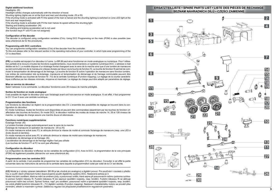
ersatzteilliste • spare parts list • liste des piÈces de rechange
(DE) Bezeichnung
DampfdomdeckelDampfdomdeckel, lack.PfeifeKessel, vollst.Führerhaus, vollst.Rauchkammertür, vollst.Senkschraube 1,7x5MotorklammerGleitbahnträger, lack.Tritt, re.Tritt, li.KurbelzapfenKuppelstange, re.Kuppelstange, li.Senkschraube, 1,7x4SpiraldruckfederPuffer, lachPuffer, balligLaterne DRLaterne GasLichteinsatz DRKupplungsdeichselTreibradsatz
KuppelradsatzBremsbacken, re.Bremsbacken, li.Steuerung, re.Steuerung, li.BodenplatteZylinderpaarKuppelhakenKupplungskopfGriffstangen (o.Abb.)Zurüstteile (o.Abb.)
(GB) Description
Steam dome coverSteam dome cover, varnish.PipeBoiler, completeCab, completeSmoke box door, completeCountersunk screw 1,7x5Motor clampGuide yoke, varnish.Tread, rightTread, leftCrankshaftsCoupling rod, rightCoupling rod, leftCountersunk screw 1,7x4Spiral compression springBuffer, latBuffer, sphericalLantern DRLantern gasLight insert DRCoupler drawbarDriving wheel setCoupled wheel setBrake shoe, rightBrake shoe, leftControl system, rightControl system, leftBase plateCylinder pairClutch hookCoupling headHandle bars (without illustr.)Accessory parts (without illustr.)
(FR) Description
Dôme à vapeurDôme à vapeur, laquéSifletChaudière, complèteCabine du conducteur, complètePorte de boîte de fumée, complèteVis à tête conique 1,7x5Pince moteur
Support de glissière, laquéMarche, droiteMarche, gaucheManeton de manivelleBarre de traction, droiteBarre de traction, gaucheVis à tête conique 1,7x4Ressort de pression en spiraleTampon, platTampon, en forme de balleLanterne DRLanterne gazElément lumière (DR)Barre d’attelageEssieu moteur
Essieu coupléSegment de frein, droiteSegment de frein, gaucheCommande, droiteCommande, gauchePlaque de sol
Paire de cylindresCrochet d’attelageTête d’attelageBarre de maintien (sans illustr.)Pièces d’équipement (sans illustr.)
1
2
3
4
5
6
7
8
9
10
11
12
13
14
15
16
17
18
19
20
21
22
23
24
25
26
27
28
29
30
(DE) achtung! Die Lok-Betriebsnummern der Artikel wechseln unter Umständen bei Neuproduktion. Ersatzteile zu den Art.-Nr. tragen die jeweils in der Produktion beindlichen Betriebsnummern. Ersatzteile mit älteren Betriebs-
nummern nur solange Vorrat reicht.
(GB) please note! The locomotive operating numbers of the articles can potentially change in the event of new production runs. Spare parts for the article number bear the operating numbers that are respectively in production.
Spare parts with older operating numbers are only available while stocks last.
(FR) attention! Les numéros d’exploitation de locomotives des articles changent parfois lors d’une nouvelle production. Les pièces de rechange relatives au n° art. portent respectivement les numéros d’exploitation se
trouvant en production. Pièces de rechange avec des numéros d’exploitation plus anciens jusqu’à rupture du stock.
!
!
!
310
94
Digital additional functions
Headlights: (f0)Headlight (white) changes automatically with the direction of travel.Shunting lighting (lights are on at the front and rear) and shunting mode: (f3 or f5)If the shunting mode is activated with F3 the speed of the train is halved and the shunting lighting is switched on (one LED light at the front and rear respectively). If the shunting mode is activated with F5 the train halves its speed without the shunting light. Starting and braking acceleration: (f4)The starting and braking acceleration set is not used(the function keys F1 and F2 are not assigned)
coniguration of the decoderThe decoder is conigured using coniguration variables (CVs). Using DCC Programming on the main (POM) is also possible (see www.uhlenbrock.de for the procedure).
Programming with DCC controllers
You can programme coniguration variables (CVs) of the decoder from the controller.To this end please refer to the relevant section in the operating instructions of your controller, in which byte-wise programming of the CV is described.
(FR) Le modèle est équipé d’un décodeur à l’usine. Le BR 89 peut ainsi fonctionner en mode analogique ou numérique. Pour l’utilisa-
tion parfaite et le recours à toutes les fonctions supplémentaires, nous recommandons un système numérique DCC. L’adresse e-mail dédiée est la 3. Le modèle dispose d’un éclairage frontal changeant avec le sens de la marche ainsi que d’une lumière de manœuvre qui est commutée lors de la manœuvre (vitesse divisée par deux) via la touche de fonction f3. La touche de fonction f4 permet de com-
muter la temporisation de démarrage et de freinage. La touche de fonction f5 active l’opération de manœuvre sans fonction lumière.Les ordres de commutation tels qu’éclairage, manœuvre et temporisation de démarrage et de freinage commutable peuvent être librement affectés aux touches de fonction f0 - f12 de la centrale numérique (Function mapping). Le réglage de la courbe caractéris-
tique s’effectue par les vitesses minimale, moyenne et maximale. Le réglage de charge peut être adapté par paramètres de réglage.
mise en service du décodeurSaisir l’adresse 3 à la commande. Le décodeur fonctionne avec 28 niveaux de marche préréglés.
sorties de fonction en mode analogiqueIl est possible de régler le décodeur pour que l’éclairage avant soit hors-service en mode analogique. À cet effet, il faut programmer la CV 13 sur 0 avec une centrale numérique.
Programmation des fonctions
Les fonctions du décodeur se règlent via la programmation des CV. L’ensemble des possibilités de réglage se trouvent dans la con-
iguration du décodeur.En mode numérique, toutes les fonctions sont disponibles et peuvent être commandées séparément par les touches de fonction (cf. affectation des touches de fonction). En mode DCC, le décodeur maîtrise les modes de niveau de marche 14, 28 et 128 niveaux de marche. Le réglage de charge assure une marche douce et silencieuse.
Fonctions numériques supplémentairesÉclairage frontal: (f0)La lumière frontale change automatiquement avec le sens de la marcheÉclairage de manœuvre et opération de manœuvre : (f3 ou f5)En mode manœuvre activé avec F3, le véhicule diminue la vitesse de moitié et commute l’éclairage de manœuvre (resp. une LED à droite devant et derrière). En mode manœuvre activé avec F5, le véhicule diminue la vitesse de moitié sans éclairage de manœuvre. Accélération de démarrage et de freinage: (f4)L’accélération de démarrage et de freinage réglée n’est pas utilisée(Les touches de fonction F1 et F2 ne sont pas affectées)
coniguration du décodeurLa coniguration du décodeur s’effectue via les variables de coniguration (CV). Avec le DCC, la programmation de la voie principale (POM) est également possible (démarche voir www.uhlenbrock.de).
Programmation avec les centrales DCC
À partir de la centrale, il est possible de programmer les variables de coniguration (CV) du décodeur. Consulter à cet effet la partie concernée dans les instructions de service de la centrale dans laquelle la programmation octet par octet de la CV est décrite.
(CZ) Model je z výroby vybaven dekodérem. BR 89 je tak vhodná pro analogový a digitální provoz. Pro používání v souladu s předlo-
hou a využití všech přídavných funkcí doporučujeme použití digitálního systému DCC. Nastavená adresa je 3. Model má čelní osvětlení, které se mění se směrem jízdy, a posunovací světlo, které sepne při posunovacím režimu (polovina rychlos-
ti) pomocí funkční klávesy f3. Funkční klávesou f4 lze sepnout zpoždění rozjezdu, resp. brzdění. Funkční klávesou f5 se aktivuje posunovací režim bez svícení. Spínací funkce, např. pro osvětlení, posunovací režim a spínatelné zpoždění rozjezdu, resp. brzdění, lze volně přidělit funkčním klávesám f0 – f12 digitální centrály (Function mapping). Nastavení charakteristiky motoru se provádí přes minimální, střední a maximální rychlost. Zátěžovou regulaci lze přizpůsobit prostřednictvím regulačních parametrů.
ersatzteilliste • spare parts list • liste des piÈces de rechange seznam náhradních dílů • czĘŚci zamienne
11
25
22
8
7
5
4
3
21
6
12
14
159 16
18
2017
1620
15
2121
23
24
11
27
26
28
DampflokBR 84 129,6
364645-S.415.05.2014
E R S A T Z T E I L L I S T E
Nicht geeignet für Kinder unter 3 Jahren
wegen abnehmbarer und verschluckbarer
Kleinteile und Verletzungsgefahr durch
funktionsbedingte scharfe Ecken und Kanten.
0-3
Te c h n i s c h e Ä n d e r u n g e n v o r b e h a l t e n !Bei Reklamationen
diese Anleitung bitte über Ihren Fachhändlermit senden an:
Achtung!Die Lok-Betriebsnummern der Artikel wechseln
unter Umständen bei Neuproduktion. Ersatzteilezu den Art.-Nr. tragen die jeweils in der Produktion
befindlichen Betriebsnummern. Ersatzteile mitälteren Betriebsnummern nur solange Vorrat reicht.
TILLIG Modellbahnen GmbHPromenade 1, 01855 Sebnitz
Lfd. Nr. Bezeichnung Art.-Nr.
123456789
1011121314151617181920212223242526272829303132333435363738394041424344454647484950515253o. Abb.o. Abb.
Rauchkammertür, vollst.Auftritt (Rauchk.)Kessel, lack.Führerhaus, vollst.Tender, vollst.Pufferteller, flachPufferteller, balligMotorklammerMotor, vollst.Hauptrahmen, lack.Bodenplatte Hauptrahmen, dek.EntstörleiterplatteLeiterplatteTritt FührerhausGriffstangen HauptrahmenUmlauf re., lack.Rahmenvorderteil, mont.Umlauf li., lack.Leiterplatte (L), mont.GleitbahnträgerAbdeckung Rahmen, mont.InnentriebwerkSteuerung re.ZylinderpaarSteuerung li.Kardanwelle 7Schaft, mont.WellenlagerZahnrad z16Zahnrad z20/z13Zahnrad z16Zahnrad z20/z13RahmendeckelSenkschraube 1,8x4,3RahmenBremsbacken HNachläufer, vollst.KupplungskopfKupplungshakenWippeAndruckfederVorläufer, vollst.Kuppelradsatz 2Kuppelradsatz 1BodenplatteBremsbacken VGetriebegehäuse BGetriebegehäuse AZahnrad z9Treibradsatz z10 m. HaftreifenKuppelradsatz 1Kuppelradsatz 2 z10 m. HaftreifenGetriebeboden, mont.ZurüstteileHaftreifen
202899302941207187202900202902316830316840302916202908207204207198396130396409302858302859207206202911207205203283302924202906302937202915202904202916306700202907302945302044302537301367302537302915393220302914302917202914300672330049302913330129202913202806202804302919302918302912302911323550203554202805203552202903202917227493
Tel. +49 (0)35971 903-0, www.tillig.com
Dieses Produkt darf am Ende seiner Nutzungsdauernicht über den normalen Hausmüll entsorgt werden, sondernmuss an einem Sammelpunkt für das Recycling von elektrischenund elektronischen Geräten abgegeben werden.Bitte fragen Sie bei Ihrem Händler oder der Gemeindeverwaltungnach der zuständigen Entsorgungsstelle.
.
3
76
54
1
2
9
10
8
13
12
11
14
161976
17
18
20
21 3130
3229
2726
33
34
24
23
25403938
44
41
4847
36
49
4645 53
34
5150
5243
393837
42
2822
3541
203272
203273203274
207445
203279
203284
29
30
19
18
17
14
10
13

58
zprovoznění dekodéruNa řídícím přístroji zadejte adresu 3. Dekodér pojede podle přednastavení s 28 jízdními stupni.
Funkční výstupy v analogovém režimuDekodér je možné nastavit tak, aby bylo v analogovém režimu vypnuto čelní osvětlení. K tomu je předtím nutné naprogramovat po-
mocí digitální centrály CV 13 na 0.
programování funkcí Funkce dekodéru se nastavují přes programování CV. Veškeré možnosti nastavení naleznete pod popisem konigurace dekodéru.V digitálním režimu jsou k dispozici všechny funkce a lze je odděleně řídit přes funkční klávesy (srov. část Obsazení funkčních kláves). V režimu DCC ovládá dekodér rychlostní mody 14, 28 a 128 rychlostních stupňů. Zátěžová regulace zajistí plynulou a tichou jízdu.
přídavné digitální funkceČelní osvětlení: (f0)Čelní světlo (bílé) se mění automaticky se směrem jízdy.Posunovací osvětlení a posunovací režim: (f3 nebo f5)Při posunovacím režimu aktivovaném pomocí F3 vozidlo sníží rychlost na polovinu a zapne posunovací světla (vždy jedna LED vpravo vpředu a vzadu). Při posunovacím režimu aktivovaném pomocí F5 vozidlo sníží rychlost na polovinu bez posunovacích světel. Zrychlení rozjezdu a brzdění: (f4)Nastavené zrychlení rozjezdu a brzdění není použito.(Funkční klávesy F1 a F2 nejsou obsazeny)
konigurace dekodéruDekodér se koniguruje prostřednictvím koniguračních proměnných (CV). Při DCC je rovněž možné programování na hlavní koleji (POM) (postup viz www.uhlenbrock.de).
programování s dcc centrálamiZ centrály můžete naprogramovat konigurační proměnné (CV) dekodéru. Dbejte prosím přitom na příslušnou část návodu k obsluze Vaší centrály, v níž je popsáno programování CV podle bytů.
(PL) Model został przez producenta wyposażony w dekoder. Dzięki temu model BR 89 jest odpowiedni zarówno do trybu analogo-
wego, jak i cyfrowego. Dla zastosowań wzorcowych i możliwości korzystania z wszystkich funkcji dodatkowych zalecamy używanie systemu cyfrowego DCC. Ustawiony adres to 3. Model jest wyposażony w oświetlenie czołowe, zmieniające się z kierunkiem jazdy oraz w światło manewrowe, włączane w biegu manewrowym (prędkość zmniejsza się o połowę) za pomocą klawisza f3. Za pomocą klawisza f4 można włączyć opóźnienie dojeżdżania i hamowania. Klawisz f5 aktywuje bieg manewrowy bez świateł. Zadania przełąc-
zania, takie jak oświetlenie, bieg manewrowy i przełączane opóźnienie dojeżdżania i hamowania można przyporządkować klawiszom funkcyjnym f0 - f12 centrali cyfrowej w dowolny sposób (function mapping). Charakterystykę silnika ustawia się za pomocą prędkości minimalnej, średniej i maksymalnej. Regulację obciążenia można dopasować za pomocą parametrów regulacyjnych.
uruchomienie dekoderaWprowadzić na sterowniku adres 3. W dekoderze ustawiono 28 stopni jazdy.
Biegi funkcyjne w trybie analogowym
Dekoder można ustawić w taki sposób, aby w trybie analogowym oświetlenie przednie było wyłączone. W tym celu należy wcześniej, za pomocą centrali cyfrowej, ustawić CV 13 na 0.
Programowanie funkcji
Funkcje dekodera można ustawić poprzez programowanie CV. Wszystkie możliwości ustawiania znaleźć można w koniguracji deko-
dera. W trybie cyfrowym dostępne są wszystkie funkcje; można nimi sterować odrębnie za pomocą klawiszy funkcyjnych (por. akapit o przyporządkowaniu klawiszy funkcyjnych). W trybie DCC dekoder może pracować w trybach stopni jazdy 14, 28 i 128. Regulacja obciążenia sprawia, że model jedzie jedwabiście miękko i cicho.
Cyfrowe funkcje dodatkowe
Oświetlenie przednie: (f0)Światło przednie (białe) zmienia się automatycznie wraz z kierunkiem jazdy.Oświetlenie manewrowe i bieg manewrowy: (f3 lub f5)W trybie manewrowym, aktywowanym klawiszem F3, prędkość pojazdu zmniejsza się o połowę i włącza się oświetlenie manewrowe (jedna dioda LED po prawej z przodu i z tyłu). W trybie manewrowym, aktywowanym klawiszem F5, prędkość pojazdu zmniejsza się o połowę, a oświetlenie manewrowe jest wyłączone. Przyśpieszenie ruszania i hamowania: (f4)Ustawione przyśpieszenie ruszania i hamowania nie jest używane. (Klawisze funkcyjne F1 i F2 nie są obłożone)
koniguracja dekoderaDekoder konigurowany jest za pomocą zmiennych koniguracji (CV). W przypadku DCC możliwe jest również programowanie szyny głównej (POM) (sposób postępowania www.uhlenbrock.de).
programowanie za pomocą central dccZ centrali można zaprogramować zmienne koniguracji (CV) dekodera. Odpowiednie informacje znaleźć można w dotyczącym tego zagadnienia rozdziale instrukcji obsługi centrali, w którym opisano bajtowe programowanie CV.
(DE) Das Modell erreicht nach einer Einlaufzeit von ca. 20 Minuten in beide Fahrtrichtungen seine optimalen Fahreigenschaften. Ab Werk ist das Modell ausreichend gefettet. Ein Nachfetten oder – ölen mit harz- und säurefreien Fett oder Öl ist erst nach ca. 100 Betriebsstunden zu empfehlen. Dazu geeignetes Fett ist unter Tillig Art.-Nr. 08973 erhältlich. Die Reinigung der Radschleifer und Radsätze zur Erhaltung der Kontaktgabe ist jedoch je nach Einsatz öfters zu empfehlen. Dazu geeignete Reinigungslüssigkeit ist unter Tillig Art.-Nr. 08977 erhältlich.Zur Wartung kann das Modell durch Lösen der 2 Verschraubungen der Bodenplatte geöffnet werden. Damit werden die Zahnräder zum Nachfetten und die Radschleifer zur Reinigung zugänglich. Von der Abnahme des Kessels und des Wasserkastens wird dringend abgeraten! Die Montage des Oberteils wird ohne Vorrichtungen nicht sicher gelingen. Für Motorwechsel bitten wir das Modell in den Tillig-Kundendienst einzuschicken.
(GB) The model achieves its optimum handling characteristics in both directions of travel after a running-in time of approx. 20 min. The model is suficiently lubricated in the factory. Re - greasing or oiling with grease or oil that is free of resin or acid is only recommended after approx. 100 operating hours. Suitable grease is available for this by ordering Tillig Art.-No. 08973. However, the cleaning of the wheel contacts and wheel sets to maintain the contact is recommended frequently depending on the application. Suitable cleaning liquid is available by ordering Tillig Art.-No. 08977.The model can be opened for maintenance purposes by detaching the 2 screw connections of the base plate. This makes the gear wheels accessible for re-greasing and the wheel contacts accessible for cleaning. We strongly advise against the removal of the boiler and the water box! The assembly of the upper part will not certainly be successful without using additional equipment. For engine changes, please return the model to the Tillig customer service team.
(FR) Après une période de rodage d’env. 20 minutes dans les deux sens de marche, le modèle atteint ses caractéristiques optima-
les de marche. Le modèle est sufisamment graissé à l’usine. Nous recommandons de regraisser ou rehuiler avec une graisse ou une huile exempte de résine et d’acide après env. 100 heures de service. La graisse adaptée est disponible chez Tillig, réf.: 08973. Cependant, nous recommandons de nettoyer les capteurs de roue et les essieux plus souvent et selon l’utilisation pour maintenir le contact. Le liquide de nettoyage adapté est disponible chez Tillig, réf.: 08977.Pour la maintenance, le modèle peut être ouvert en desserrant les 2 vissages de la plaque de sol. Cela permet l’accès aux roues dentées pour le graissage et aux capteurs de roue pour le nettoyage. Il est absolument déconseillé de retirer la chaudière et le ré-
servoir à eau. Le bon montage de la partie supérieure n’est pas garanti sans dispositifs. Pour remplacer le moteur, veuillez envoyer le modèle au SAV Tillig.
(CZ) Model dosáhne po době záběhu zhruba 20 minut v obou jízdních směrech své optimální jízdní vlastnosti. Z výroby je model dostatečně promazán. Další mazání či olejování mazivem bez obsahu pryskyřic a kyselin se doporučuje po cca 100 provozních ho-
dinách. Jako vhodné mazivo je k dostání výrobek Tillig s artiklovým číslem 08973. Čištění sběračů a dvojkolí pro zachování kontaktu však doporučujeme provádět častěji v závislosti na používání. Vhodným tekutým čističem je výrobek Tillig s artiklovým číslem 08977.K provádění údržby lze model otevřít uvolněním 2 šroubových spojů podlahové desky. Tím se zpřístupní ozubená kola k domazání a kolové sběrače k čištění. Důrazně varujeme před odejmutím kotle a nádrže na vodu! Montáž horního dílu není bezpečně provedi-telná bez speciálních přípravků. Pro výměnu motoru model prosím zašlete do servisu Tillig.
(PL) Model po ok. 20 minutach docierania osiąga optymalne właściwości jezdne w obu kierunkach jazdy. Model został dostatecznie nasmarowany przez producenta. Powtórne smarowanie lub oliwienie za pomocą wolnego od żywic i kwasów smaru lub oleju zaleca się dopiero po ok. 100 godzinach eksploatacji. Odpowiedni do tego celu smar dostępny jest pod nr art. Tillig 08973. Częściej jednak, zależnie od eksploatacji, zaleca się, dla zachowania zestyku, czyszczenie ślizgaczy kołowych i zespołów kół. Odpowiedni do tego celu płyn czyszczący dostępny jest pod nr art. Tillig 08977.W celu konserwacji model można otworzyć odkręcając 2 połączenia śrubowe na płytce spodniej. Dostępne są wtedy koła zębate do smarowania i ślizgacze kołowe do czyszczenia. Odradza się usilnie zdejmowania kotła i zbiornika wodnego! Części górnej nie da się zmontować w bezpieczny sposób bez odpowiednich przyrządów. W celu wymiany silnika prosimy o przesłanie modelu do serwisu irmy Tillig.
Wartung • maintenance • numérisation • Údržba • obsŁuga i konserWacJa
364645-S.215.05.2014
DI G I TA L I S I ERUN G
Das Modell ist ab Werk ausreichend gefettet. Ein Nachfetten ist erst nachca. 100 Betriebsstunden erforderlich.Dabei sind alle beweglichen Teile der Steuerung und die Lokradsätze miteinem Tropfen säure- und harzfreiem Öl zu versehen. Die Zahnräder desAntriebes sind mit technischer Vaseline zu fetten.Bei Verwendung von zu viel Fett und Öl besteht infolge Verschmutzung dieGefahr von Betriebsstörungen.
W A R T U N G
Gestänge und Radsätze ölen
Bitte prüfen Sie vor Inbetriebnahme der Lok die Spannung an Ihrer Digitalzentrale. Für den Betrieb von Fahrzeugen der Spurweiten TT, H0,H0e und H0m wird eine Digitalspannung von max. 14 Volt empfohlen. Höhere Spannungen führen zu einem höheren Verschleiß derMotoren. Decoderdefekte (durch Überlast), die durch diese Ursache entstehen, fallen nicht unter die Gewährleistung.
Die Digitalisierung kann mit einem Decoder mit sechspoliger Schnittstelle vorgenommen werden. Wir empfehlen die Verwendung eines Decodersvon Uhlenbrock (TILLIG-Art. Nr. 66021).Zum Einbau des Decoders ist die Lok teilweise zu demontieren. Nach dem Abziehen des Tenders vom Führerhaus nach hinten (Abb. 3E), kann dasFührerhaus unten gespreizt und nach oben vom Kessel abgenommen werden (Abb. 3F). Die nun sichtbare Abdeckung über dem Entstörsatz wirdnach oben abgezogen (Abb. 3G). Danach kann der Entstörsatz gegen den Decoder ausgetauscht werden. Der Zusammenbau erfolgt inumgekehrter Reihenfolge.
DampflokBR 84 129,6
A
B
C
C D
D
G
E
FH
Abb. 3
Abb. 2Abb. 1
(DE) Gestänge und Radsätze ölen
(GB) lubricating rods and wheel sets • (FR) Huiler la tringlerie et les essieux
(CZ) tyčoví a kola olejovat • (PL) smarowanie wiązarów i zestawów kołowych
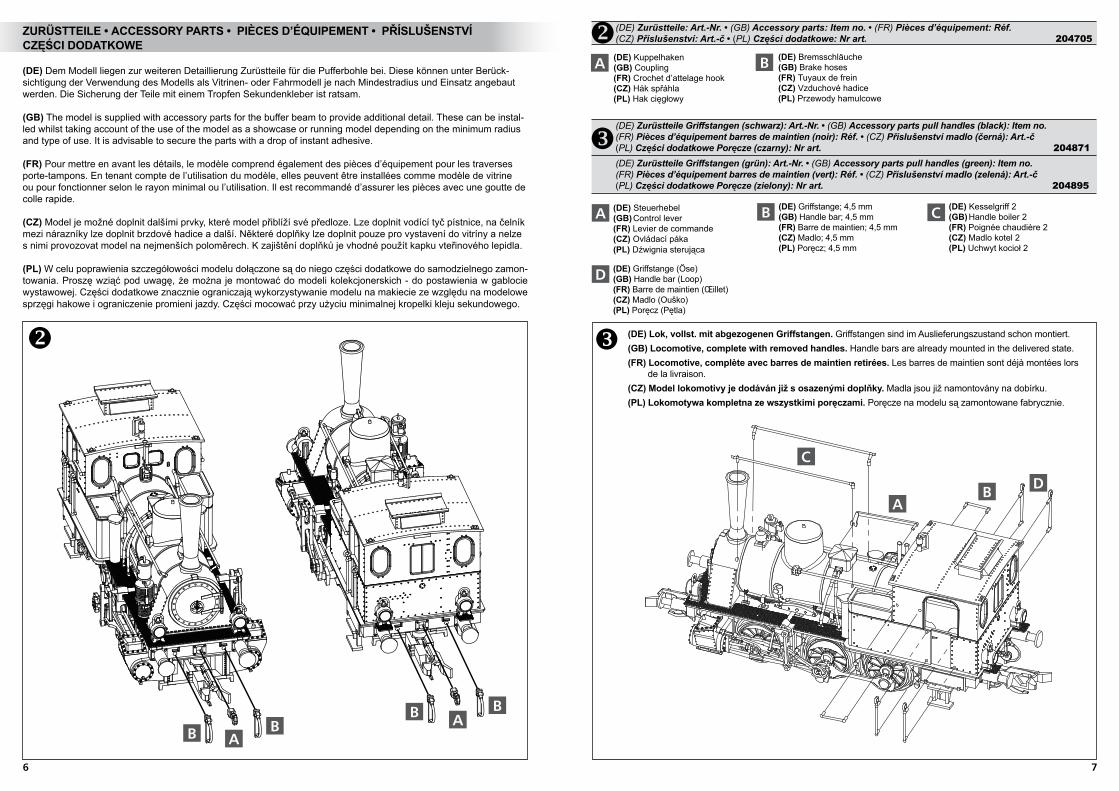
(DE) Dem Modell liegen zur weiteren Detaillierung Zurüstteile für die Pufferbohle bei. Diese können unter Berück-
sichtigung der Verwendung des Modells als Vitrinen- oder Fahrmodell je nach Mindestradius und Einsatz angebaut werden. Die Sicherung der Teile mit einem Tropfen Sekundenkleber ist ratsam.
(GB) The model is supplied with accessory parts for the buffer beam to provide additional detail. These can be instal-led whilst taking account of the use of the model as a showcase or running model depending on the minimum radius and type of use. It is advisable to secure the parts with a drop of instant adhesive.
(FR) Pour mettre en avant les détails, le modèle comprend également des pièces d’équipement pour les traverses porte-tampons. En tenant compte de l’utilisation du modèle, elles peuvent être installées comme modèle de vitrine ou pour fonctionner selon le rayon minimal ou l’utilisation. Il est recommandé d’assurer les pièces avec une goutte de colle rapide.
(CZ) Model je možné doplnit dalšími prvky, které model přiblíží své předloze. Lze doplnit vodící tyč pístnice, na čelník mezi nárazníky lze doplnit brzdové hadice a další. Některé doplňky lze doplnit pouze pro vystavení do vitríny a nelze s nimi provozovat model na nejmenších poloměrech. K zajištění doplňků je vhodné použít kapku vteřinového lepidla.
(PL) W celu poprawienia szczegółowości modelu dołączone są do niego części dodatkowe do samodzielnego zamon-
towania. Proszę wziąć pod uwagę, że można je montować do modeli kolekcjonerskich - do postawienia w gablocie wystawowej. Części dodatkowe znacznie ograniczają wykorzystywanie modelu na makiecie ze względu na modelowe sprzęgi hakowe i ograniczenie promieni jazdy. Części mocować przy użyciu minimalnej kropelki kleju sekundowego.
B(DE) Bremsschläuche(GB) Brake hoses(FR) Tuyaux de frein(CZ) Vzduchové hadice (PL) Przewody hamulcowe
A(DE) Kuppelhaken (GB) Coupling(FR) Crochet d’attelage hook (CZ) Hák spřáhla(PL) Hak cięgłowy
ABB
B BA
zurÜstteile • accessory parts • piÈces d’éQuipement • příslušenstVí czĘŚci dodatkoWe
(DE) Lok, vollst. mit abgezogenen Griffstangen. Griffstangen sind im Auslieferungszustand schon montiert.(GB) Locomotive, complete with removed handles. Handle bars are already mounted in the delivered state.(Fr) locomotive, complète avec barres de maintien retirées. Les barres de maintien sont déjà montées lors de la livraison.(cz) model lokomotivy je dodáván již s osazenými doplňky. Madla jsou již namontovány na dobírku.(pl) lokomotywa kompletna ze wszystkimi poręczami. Poręcze na modelu są zamontowane fabrycznie.
(DE) Zurüstteile Griffstangen (schwarz): Art.-Nr. • (GB) Accessory parts pull handles (black): Item no. (FR) Pièces d’équipement barres de maintien (noir): Réf. • (CZ) Příslušenství madlo (černá): Art.-č
(PL) Części dodatkowe Poręcze (czarny): Nr art. 204871
A(DE) Steuerhebel (GB) Control lever (FR) Levier de commande(CZ) Ovládací páka(PL) Dźwignia sterująca
B(DE) Griffstange; 4,5 mm (GB) Handle bar; 4,5 mm(FR) Barre de maintien; 4,5 mm (CZ) Madlo; 4,5 mm (PL) Poręcz; 4,5 mm
C(DE) Kesselgriff 2(GB) Handle boiler 2(FR) Poignée chaudière 2(CZ) Madlo kotel 2(PL) Uchwyt kocioł 2
D(DE) Griffstange (Öse)(GB) Handle bar (Loop)(FR) Barre de maintien (œillet) (CZ) Madlo (Ouško)(PL) Poręcz (Pętla)
(DE) Zurüstteile: Art.-Nr. • (GB) Accessory parts: Item no. • (FR) Pièces d’équipement: Réf.(CZ) Příslušenství: Art.-č • (PL) Części dodatkowe: Nr art. 204705
76
(DE) Zurüstteile Griffstangen (grün): Art.-Nr. • (GB) Accessory parts pull handles (green): Item no. (FR) Pièces d’équipement barres de maintien (vert): Réf. • (CZ) Příslušenství madlo (zelená): Art.-č
(PL) Części dodatkowe Poręcze (zielony): Nr art. 204895
C
AB
D
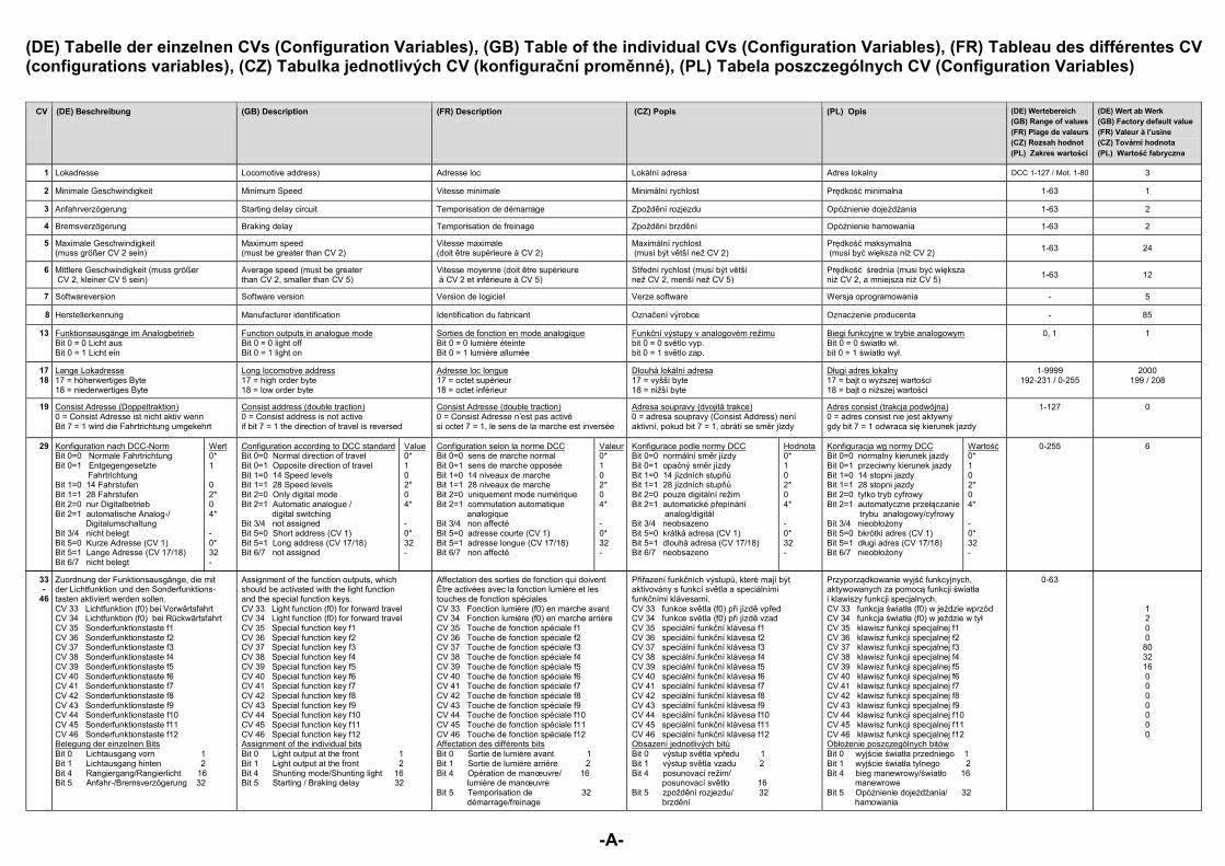
(DE) Tabelle der einzelnen CVs (Configuration Variables), (GB) Table of the individual CVs (Configuration Variables), (FR) Tableau des différentes CV (configurations variables), (CZ) Tabulka jednotlivých CV (konfigurační proměnné), (PL) Tabela poszczególnych CV (Configuration Variables)
CV
(DE) Beschreibung (GB) Description (FR) Description (CZ) Popis (PL) Opis (DE) Wertebereich (GB) Range of values (FR) Plage de valeurs (CZ) Rozsah hodnot (PL) Zakres wartości
(DE) Wert ab Werk (GB) Factory default value (FR) Valeur à l’usine (CZ) Tovární hodnota (PL) Wartość fabryczna
1 Lokadresse Locomotive address) Adresse loc Lokální adresa Adres lokalny DCC 1-127 / Mot. 1-80 3
2 Minimale Geschwindigkeit Minimum Speed Vitesse minimale Minimální rychlost Prędkość minimalna 1-63 1
3 Anfahrverzögerung Starting delay circuit Temporisation de démarrage Zpoždění rozjezdu Opóźnienie dojeżdżania 1-63 2
4 Bremsverzögerung Braking delay Temporisation de freinage Zpoždění brzdění Opóźnienie hamowania 1-63 2
5 Maximale Geschwindigkeit (muss größer CV 2 sein)
Maximum speed (must be greater than CV 2)
Vitesse maximale (doit être supérieure à CV 2)
Maximální rychlost (musí být větší než CV 2)
Prędkość maksymalna (musi być większa niż CV 2) 1-63 24
6 Mittlere Geschwindigkeit (muss größer CV 2, kleiner CV 5 sein)
Average speed (must be greater than CV 2, smaller than CV 5)
Vitesse moyenne (doit être supérieure à CV 2 et inférieure à CV 5)
Střední rychlost (musí být větší než CV 2, menší než CV 5)
Prędkość średnia (musi być większa niż CV 2, a mniejsza niż CV 5) 1-63 12
7 Softwareversion Software version Version de logiciel Verze software Wersja oprogramowania - 5
8 Herstellerkennung Manufacturer identification Identification du fabricant Označení výrobce Oznaczenie producenta - 85
13 Funktionsausgänge im Analogbetrieb Bit 0 = 0 Licht aus Bit 0 = 1 Licht ein
Function outputs in analogue mode Bit 0 = 0 light off Bit 0 = 1 light on
Sorties de fonction en mode analogique Bit 0 = 0 lumière éteinte Bit 0 = 1 lumière allumée
Funkční výstupy v analogovém režimu bit 0 = 0 světlo vyp. bit 0 = 1 světlo zap.
Biegi funkcyjne w trybie analogowym Bit 0 = 0 światło wł. bit 0 = 1 światło wył.
0, 1 1
17 18
Lange Lokadresse 17 = höherwertiges Byte 18 = niederwertiges Byte
Long locomotive address 17 = high order byte 18 = low order byte
Adresse loc longue 17 = octet supérieur 18 = octet inférieur
Dlouhá lokální adresa 17 = vyšší byte 18 = nižší byte
Długi adres lokalny 17 = bajt o wyższej wartości 18 = bajt o niższej wartości
1-9999 192-231 / 0-255
2000 199 / 208
19 Consist Adresse (Doppeltraktion) 0 = Consist Adresse ist nicht aktiv wenn Bit 7 = 1 wird die Fahrtrichtung umgekehrt
Consist address (double traction) 0 = Consist address is not active if bit 7 = 1 the direction of travel is reversed
Consist Adresse (double traction) 0 = Consist Adresse n’est pas activé si octet 7 = 1, le sens de la marche est inversée
Adresa soupravy (dvojitá trakce) 0 = adresa soupravy (Consist Address) není aktivní, pokud bit 7 = 1, obrátí se směr jízdy
Adres consist (trakcja podwójna) 0 = adres consist nie jest aktywny gdy bit 7 = 1 odwraca się kierunek jazdy
1-127 0
29 Konfiguration nach DCC-Norm Bit 0=0 Normale Fahrtrichtung Bit 0=1 Entgegengesetzte Fahrtrichtung Bit 1=0 14 Fahrstufen Bit 1=1 28 Fahrstufen Bit 2=0 nur Digitalbetrieb Bit 2=1 automatische Analog-/ Digitalumschaltung Bit 3/4 nicht belegt Bit 5=0 Kurze Adresse (CV 1) Bit 5=1 Lange Adresse (CV 17/18) Bit 6/7 nicht belegt
Wert 0* 1 0 2* 0 4* - 0* 32 -
Configuration according to DCC standard Bit 0=0 Normal direction of travel Bit 0=1 Opposite direction of travel Bit 1=0 14 Speed levels Bit 1=1 28 Speed levels Bit 2=0 Only digital mode Bit 2=1 Automatic analogue / digital switching Bit 3/4 not assigned Bit 5=0 Short address (CV 1) Bit 5=1 Long address (CV 17/18) Bit 6/7 not assigned
Value 0* 1 0 2* 0 4* - 0* 32 -
Configuration selon la norme DCC Bit 0=0 sens de marche normal Bit 0=1 sens de marche opposée Bit 1=0 14 niveaux de marche Bit 1=1 28 niveaux de marche Bit 2=0 uniquement mode numérique Bit 2=1 commutation automatique analogique Bit 3/4 non affecté Bit 5=0 adresse courte (CV 1) Bit 5=1 adresse longue (CV 17/18) Bit 6/7 non affecté
Valeur 0* 1 0 2* 0 4* - 0* 32 -
Konfigurace podle normy DCC Bit 0=0 normální směr jízdy Bit 0=1 opačný směr jízdy Bit 1=0 14 jízdních stupňů Bit 1=1 28 jízdních stupňů Bit 2=0 pouze digitální režim Bit 2=1 automatické přepínání analog/digitál Bit 3/4 neobsazeno Bit 5=0 krátká adresa (CV 1) Bit 5=1 dlouhá adresa (CV 17/18) Bit 6/7 neobsazeno
Hodnota 0* 1 0 2* 0 4* - 0* 32 -
Konfiguracja wg normy DCC Bit 0=0 normalny kierunek jazdy Bit 0=1 przeciwny kierunek jazdy Bit 1=0 14 stopni jazdy Bit 1=1 28 stopni jazdy Bit 2=0 tylko tryb cyfrowy Bit 2=1 automatyczne przełączanie trybu analogowy/cyfrowy Bit 3/4 nieobłożony Bit 5=0 bkrótki adres (CV 1) Bit 5=1 długi adres (CV 17/18) Bit 6/7 nieobłożony
Wartość 0* 1 0 2* 0 4* - 0* 32 -
0-255 6
33 -
46
Zuordnung der Funktionsausgänge, die mit der Lichtfunktion und den Sonderfunktions- tasten aktiviert werden sollen. CV 33 Lichtfunktion (f0) bei Vorwärtsfahrt CV 34 Lichtfunktion (f0) bei Rückwärtsfahrt CV 35 Sonderfunktionstaste f1 CV 36 Sonderfunktionstaste f2 CV 37 Sonderfunktionstaste f3 CV 38 Sonderfunktionstaste f4 CV 39 Sonderfunktionstaste f5 CV 40 Sonderfunktionstaste f6 CV 41 Sonderfunktionstaste f7 CV 42 Sonderfunktionstaste f8 CV 43 Sonderfunktionstaste f9 CV 44 Sonderfunktionstaste f10 CV 45 Sonderfunktionstaste f11 CV 46 Sonderfunktionstaste f12 Belegung der einzelnen Bits Bit 0 Lichtausgang vorn 1 Bit 1 Lichtausgang hinten 2 Bit 4 Rangiergang/Rangierlicht 16 Bit 5 Anfahr-/Bremsverzögerung 32
Assignment of the function outputs, which should be activated with the light function and the special function keys. CV 33 Light function (f0) for forward travel CV 34 Light function (f0) for forward travel CV 35 Special function key f1 CV 36 Special function key f2 CV 37 Special function key f3 CV 38 Special function key f4 CV 39 Special function key f5 CV 40 Special function key f6 CV 41 Special function key f7 CV 42 Special function key f8 CV 43 Special function key f9 CV 44 Special function key f10 CV 45 Special function key f11 CV 46 Special function key f12 Assignment of the individual bits Bit 0 Light output at the front 1 Bit 1 Light output at the front 2 Bit 4 Shunting mode/Shunting light 16 Bit 5 Starting / Braking delay 32
Affectation des sorties de fonction qui doivent Être activées avec la fonction lumière et les touches de fonction spéciales CV 33 Fonction lumière (f0) en marche avant CV 34 Fonction lumière (f0) en marche arrière CV 35 Touche de fonction spéciale f1 CV 36 Touche de fonction spéciale f2 CV 37 Touche de fonction spéciale f3 CV 38 Touche de fonction spéciale f4 CV 39 Touche de fonction spéciale f5 CV 40 Touche de fonction spéciale f6 CV 41 Touche de fonction spéciale f7 CV 42 Touche de fonction spéciale f8 CV 43 Touche de fonction spéciale f9 CV 44 Touche de fonction spéciale f10 CV 45 Touche de fonction spéciale f11 CV 46 Touche de fonction spéciale f12 Affectation des différents bits Bit 0 Sortie de lumière avant 1 Bit 1 Sortie de lumière arrière 2 Bit 4 Opération de manœuvre/ 16 lumière de manœuvre Bit 5 Temporisation de 32 démarrage/freinage
Přiřazení funkčních výstupů, které mají být aktivovány s funkcí světla a speciálními funkčními klávesami. CV 33 funkce světla (f0) při jízdě vpřed CV 34 funkce světla (f0) při jízdě vzad CV 35 speciální funkční klávesa f1 CV 36 speciální funkční klávesa f2 CV 37 speciální funkční klávesa f3 CV 38 speciální funkční klávesa f4 CV 39 speciální funkční klávesa f5 CV 40 speciální funkční klávesa f6 CV 41 speciální funkční klávesa f7 CV 42 speciální funkční klávesa f8 CV 43 speciální funkční klávesa f9 CV 44 speciální funkční klávesa f10 CV 45 speciální funkční klávesa f11 CV 46 speciální funkční klávesa f12 Obsazení jednotlivých bitů Bit 0 výstup světla vpředu 1 Bit 1 výstup světla vzadu 2 Bit 4 posunovací režim/ posunovací světlo 16 Bit 5 zpoždění rozjezdu/ 32 brzdění
Przyporządkowanie wyjść funkcyjnych, aktywowanych za pomocą funkcji światła i klawiszy funkcji specjalnych. CV 33 funkcja światła (f0) w jeździe wprzód CV 34 funkcja światła (f0) w jeździe w tył CV 35 klawisz funkcji specjalnej f1 CV 36 klawisz funkcji specjalnej f2 CV 37 klawisz funkcji specjalnej f3 CV 38 klawisz funkcji specjalnej f4 CV 39 klawisz funkcji specjalnej f5 CV 40 klawisz funkcji specjalnej f6 CV 41 klawisz funkcji specjalnej f7 CV 42 klawisz funkcji specjalnej f8 CV 43 klawisz funkcji specjalnej f9 CV 44 klawisz funkcji specjalnej f10 CV 45 klawisz funkcji specjalnej f11 CV 46 klawisz funkcji specjalnej f12 Obłożenie poszczególnych bitów Bit 0 wyjście światła przedniego 1 Bit 1 wyjście światła tylnego 2 Bit 4 bieg manewrowy/światło 16 manewrowe Bit 5 Opóźnienie dojeżdżania/ 32 hamowania
0-63
1 2 0 0
80 32 16 0 0 0 0 0 0 0
49 ert ue
d’émission LISSY
d’ordres de marche et ne peut qu’être
eur
přípojky světla nezaměňovatpřípojky světla zaměňovatbrzdění pouze s
brzdění snapětím
vypnutý přes bit 3 a formát DCC přes bit 4, nedostává dekodér žádné povely
jízdě a lze ho pouze programovat.
ota wy Bit 0=0 regulacja silnika wł.Bit 0=1 regulacja silnika wył. Bit 2=0 SUSI konfig. dla modułu
dźwiękowego
modułu nadawczego
Bit 6=0 nie zamieniać przyłączy światła
Bit 6=1 zamienić przyłącza światła
sygnałem
Bit 7=1 hamowanie z napięciem
Uwaga: Jeżeli format Motoroli
są wyłączone, to dekoder nie otrzymuje już poleceń jazdy i można go tylko programować.
Wartość
50 Tlumení výstupů světla Ściemnianie wyjść światła
51 Analogový jízdní režim
52
53 Tempo powtórzeń regulacji silnika
54
změnit jízdním stupněm 7 neměnit
tempo powtórzeń regulacji silnika stałeBit 2=1 zmiana tempa powtórzeń regulacji
7 nie zmieniać
-a-
(DE) Tabelle der einzelnen CVs (Configuration Variables), (GB) Table of the individual CVs (Configuration Variables), (FR) Tableau des différentes CV (configurations variables), (CZ) Tabulka jednotlivých CV (konfigurační proměnné), (PL) Tabela poszczególnych CV (Configuration Variables)
CV (DE) Beschreibung (GB) Description (FR) Description (CZ) Popis (PL) Opis (DE) Wertebereich (GB) Range of values (FR) Plage de valeurs (CZ) Rozsah hodnot (PL) Zakres wartości
(DE) Wert ab Werk (GB) Factory default value (FR) Valeur à l’usine (CZ) Tovární hodnota (PL) Wartość fabryczna
1 80
2 Prędkość minimalna
3 Zpoždění rozjezdu Opóźnienie dojeżdżania
4 Zpoždění brzdění Opóźnienie hamowania
5 (musí být větší než CV 2)
Prędkość maksymalna(musi być większa niż CV 2)
6 Střední rychlost (musí být větší než CV 2, menší než CV 5)
Prędkość średnia (musi być większa niż CV 2, a mniejsza niż CV 5)
7
8 Označení výrobce
13 Funkční výstupy v analogovém režimubit 0 = 0 světlo vyp. bit 0 = 1 světlo zap.
Bit 0 = 0 światło wł.bit 0 = 1 światło wył.
17 18 17 = vyšší byte
18 = nižší byte
Długi adres lokalny17 = bajt o wyższej wartości
= bajt o niższej wartości
19 0 = Consist Adresse n’est pas activé
pokud bit 7 = 1, obrátí se směr jízdy gdy bit 7 = 1 odwraca się kierunek jazdy
29 ert ard ue eur normální směr jízdyopačný směr jízdy14 jízdních stupňů 28 jízdních stupňůpouze digitální režimautomatické přepínání
ota
Bit 2=1 automatyczne przełączanie
Bit 3/4 nieobłożony
Bit 5=1 długi adres (CVBit 6/7 nieobłożony
Wartość
-B-
(DE) Tabelle der einzelnen CVs (Configuration Variables), (GB) Table of the individual CVs (Configuration Variables), (FR) Tableau des différentes CV (configurations variables), (CZ) Tabulka jednotlivých CV (konfigurační proměnné), (PL) Tabela poszczególnych CV (Configuration Variables)
CV
(DE) Beschreibung (GB) Description (FR) Description (CZ) Popis (PL) Opis (DE) Wertebereich (GB) Range of values (FR) Plage de valeurs (CZ) Rozsah hodnot (PL) Zakres wartości
(DE) Wert ab Werk (GB) Factory default value (FR) Valeur à l’usine (CZ) Tovární hodnota (PL) Wartość fabryczna
1 80
2 Prędkość minimalna
3 Zpoždění rozjezdu Opóźnienie dojeżdżania
4 Zpoždění brzdění Opóźnienie hamowania
5 (musí být větší než CV 2)
Prędkość maksymalna(musi być większa niż CV 2)
6 Střední rychlost (musí být větší než CV 2, menší než CV 5)
Prędkość średnia (musi być większa niż CV 2, a mniejsza niż CV 5)
7
8 Označení výrobce
13 Funkční výstupy v analogovém režimubit 0 = 0 světlo vyp. bit 0 = 1 světlo zap.
Bit 0 = 0 światło wł.bit 0 = 1 światło wył.
17 18 17 = vyšší byte
18 = nižší byte
Długi adres lokalny17 = bajt o wyższej wartości
= bajt o niższej wartości
19 0 = Consist Adresse n’est pas activé
pokud bit 7 = 1, obrátí se směr jízdy gdy bit 7 = 1 odwraca się kierunek jazdy
29 ert ard ue eur normální směr jízdyopačný směr jízdy14 jízdních stupňů 28 jízdních stupňůpouze digitální režimautomatické přepínání
ota
Bit 2=1 automatyczne przełączanie
Bit 3/4 nieobłożony
Bit 5=1 długi adres (CVBit 6/7 nieobłożony
Wartość
33 -
46
Přiřazení funkčních výstupů, které mají být s funkcí světla a speciálními
funkčními klávesami.funkce světla (f0) při jízdě vpřed funkce světla (f0) při jízdě vzad speciální funkční klávesa f1 speciální funkční klávesa f2speciální funkční klávesa f3speciální funkční klávesa f4speciální funkční klávesa f5speciální funkční kspeciální funkční klávesa f7speciální funkční klávesa f8speciální funkční klávesa f9speciální funkční klávesa f10speciální funkční klávesa f11speciální funkční klávesa f12
bitůýstup světla vpředu
výstup světla vzaduposunovací režim/posunovací světlo zpoždění rozjezdu/brzdění
Przyporządkowanie wyjść aktywowanych za pomocą funkcji światła
33 funkcja światła (f0) w jeździe wprzód34 funkcja światła (f0) w jeździe w tył
Obłożenie poszczególnych bitówBit 0 wyjście światła przedniego Bit 1 wyjście światła tylnegoBit 4 bieg manewrowy/światło
Bit 5 Opóźnienie dojeżdżania/
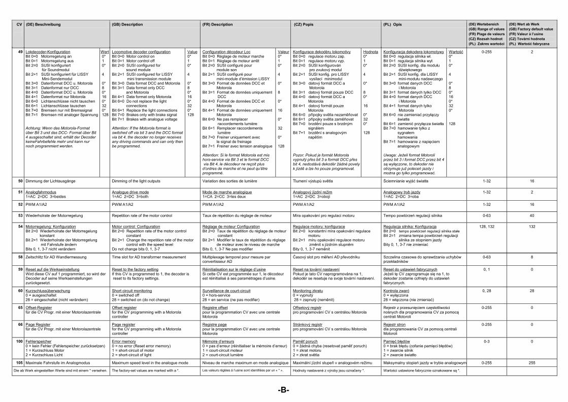
49 Lokdecoder-Konfiguration Bit 0=0 Motorregelung an Bit 0=1 Motorregelung aus Bit 2=0 SUSI konfiguriert für Soundmodul Bit 2=1 SUSI konfiguriert für LISSY Mini-Sendemodul Bit 3=0 Datenformat DCC u. Motorola Bit 3=1 Datenformat nur DCC Bit 4=0 Datenformat DCC u. Motorola Bit 4=1 Datenformat nur Motorola Bit 6=0 Lichtanschlüsse nicht tauschen Bit 6=1 Lichtanschlüsse tauschen Bit 7=0 Bremsen nur mit Bremssignal Bit 7=1 Bremsen mit analoger Spannung Achtung: Wenn das Motorola-Format über Bit 3 und das DCC- Format über Bit 4 ausgeschaltet sind, erhält der Decoder keineFahrbefehle mehr und kann nur noch programmiert werden.
Wert 0* 1 0* 4 0* 8 0* 16 0* 32 0* 128
Locomotive decoder configuration Bit 0=0 Motor control on Bit 0=1 Motor control off Bit 2=0 SUSI configured for sound module Bit 2=1 SUSI configured for LISSY mini transmission module Bit 3=0 Data format DCC and Motorola Bit 3=1 Data format only DCC and Motorola Bit 4=1 Data format only Motorola Bit 6=0 Do not replace the light connections Bit 6=1 Replace the light connections Bit 7=0 Brakes only with brake signal Bit 7=1 Brakes with analogue voltage Attention: If the Motorola format is switched off via bit 3 and the DCC format via bit 4, the decoder no longer receives any driving commands and can only then be programmed.
Value 0* 1 0* 4 0* 8 0* 16 0* 32 0* 128
Configuration décodeur Loc Bit 0=0 Réglage de moteur marche Bit 0=1 Réglage de moteur arrêt Bit 2=0 SUSI configuré pour module son Bit 2=1 SUSI configuré pour mini-module d’émission LISSY Bit 3=0 Format de données DCC et Motorola Bit 3=1 Format de données uniquement DCC Bit 4=0 Format de données DCC et Motorola Bit 4=1 Format de données uniquement Motorola Bit 6=0 Ne pas remplacer raccordements lumière Bit 6=1 Remplacer raccordements lumière Bit 7=0 Freiner uniquement avec le signal de freinage Bit 7=1 Freiner avec tension analogique Attention: Si le format Motorola est mis hors-service via Bit 3 et le format DCC via Bit 4, le décodeur ne reçoit plus d’ordres de marche et ne peut qu’être programmé.
Valeur 0* 1 0* 4 0* 8 0* 16 0* 32 0* 128
Konfigurace dekodéru lokomotivy Bit 0=0 regulace motoru zap. Bit 0=1 regulace motoru vyp. Bit 2=0 SUSI konfigurován pro zvukový modul Bit 2=1 SUSI konfig. pro LISSY vysílací minimodul Bit 3=0 datový formát DCC a Motorola Bit 3=1 datový formát pouze DCC Bit 4=0 datový formát DCC a Motorola Bit 4=1 datový formát pouze Motorola Bit 6=0 přípojky světla nezaměňovat Bit 6=1 přípojky světla zaměňovat Bit 7=0 brzdění pouze s brzdným signálem Bit 7=1 brzdění s analogovým napětím Pozor: Pokud je formát Motorola vypnutý přes bit 3 a formát DCC přes bit 4, nedostává dekodér žádné povely k jízdě a lze ho pouze programovat.
Hodnota 0* 1 0* 4 0* 8 0* 16 0* 32 0* 128
Konfiguracja dekodera lokomotywy Bit 0=0 regulacja silnika wł. Bit 0=1 regulacja silnika wył. Bit 2=0 SUSI konfig. dla modułu dźwiękowego Bit 2=1 SUSI konfig. dla LISSY mini-modułu nadawczego Bit 3=0 format danych DCC i Motorola Bit 3=1 format danych tylko DCC Bit 4=0 format danych DCC i Motorola Bit 4=1 format danych tylko Motorola Bit 6=0 nie zamieniać przyłączy światła Bit 6=1 zamienić przyłącza światła Bit 7=0 hamowanie tylko z sygnałem hamowania Bit 7=1 hamowanie z napięciem analogowym Uwaga: Jeżeli format Motoroli przez bit 3 i format DCC przez bit 4 są wyłączone, to dekoder nie otrzymuje już poleceń jazdy i można go tylko programować.
Wartość 0* 1 0* 4 0* 8 0* 16 0* 32 0* 128
0-255 2
50 Dimmung der Lichtausgänge Dimming of the light outputs Variation des sorties de lumière Tlumení výstupů světla Ściemnianie wyjść światła 1-32 16
51 Analogfahrmodus 1=AC 2=DC 3=beides
Analogue drive mode 1=AC 2=DC 3=both
Mode de marche analogique 1=CA 2=CC 3=les deux
Analogový jízdní režim 1=AC 2=DC 3=obojí
Analogowy tryb jazdy 1=AC 2=DC 3=oba
1-32 2
52 PWM A1/A2 PWM A1/A2 PWM A1/A2 PWM A1/A2 PWM A1/A2 1-32 16
53 Wiederholrate der Motorregelung Repetition rate of the motor control Taux de répétition du réglage de moteur Míra opakování pro regulaci motoru Tempo powtórzeń regulacji silnika 0-63 40
54 Motorregelung: Konfiguration Bit 2=0 Wiederholrate der Motorregelung konstant Bit 2=1 Wiederholrate der Motorregelung mit Fahrstufe ändern Bits 0, 1, 3-7 nicht verändern
Motor control: Configuration Bit 2=0 Repetition rate of the motor control constant Bit 2=1 Change the repetition rate of the motor control with the speed level Do not change bits 0, 1, 3-7
Réglage de moteur Configuration Bit 2=0 Taux de répétition du réglage de moteur constant Bit 2=1 Modifier le taux de répétition du réglage de moteur avec le niveau de marche Bits 0, 1, 3-7 Ne pas modifier
Regulace motoru: konfigurace Bit 2=0 konstantní míra opakování regulace motoru Bit 2=1 míru opakování regulace motoru změnit s jízdním stupněm Bity 0, 1, 3-7 neměnit
Regulacja silnika: Konfiguracja Bit 2=0 tempo powtórzeń regulacji silnika stałe Bit 2=1 zmiana tempa powtórzeń regulacji silnika ze stopniem jazdy Bity 0, 1, 3-7 nie zmieniać
128, 132 132
58 Zeitschlitz für AD Wandlermessung Time slot for AD transformer measurement Multiplexage temporel pour mesure par convertisseur AD
Časový slot pro měření AD převodníku Szczelina czasowa do sprawdzania uchybów przekładników
0-63 8
59 Reset auf die Werkseinstellung Wird diese CV auf 1 programmiert, so wird der Decoder auf seine Werkseinstellungen zurückgesetzt.
Reset to the factory setting If this CV is programmed to 1, the decoder is reset to its factory settings.
Réinitialisation sur le réglage d’usine Si cette CV est programmée sur 1, le décodeur est réinitialisé à ses paramétrages d’usine.
Reset na tovární nastavení Pokud je tato CV naprogramována na 1, dekodér se resetuje na svoje tovární nastavení.
Reset do ustawień fabrycznych Jeżeli tę CV zaprogramuje się na 1, to dekoder zostanie cofnięty do ustawień fabrycznych.
0, 1 0
60 Kurzschlussüberwachung 0 = ausgeschaltet 28 = eingeschaltet (nicht verändern)
Short circuit monitoring 0 = switched off 28 = switched on (do not change)
Surveillance de court-circuit 0 = hors-service 28 = en service (ne pas modifier)
Monitoring zkratu 0 = vypnutý 28 = zapnutý (neměnit)
Kontrola zwarć 0 = wyłączona 28 = włączona (nie zmieniać)
0, 28 28
65 Offset-Register für die CV Progr. mit einer Motorolazentrale
Offset register for the CV programming with a Motorola controller
Registre offset pour la programmation CV avec une centrale Motorola
Offsetový registr pro programování CV s centrálou Motorola
Rejestr z przesunięciem częstotliwości nośnych dla programowania CV za pomocą centrali Motoroli
0-255 0
66 Page Register für die CV Progr. mit einer Motorolazentrale
Page register for the CV programming with a Motorola controller
Registre page pour la programmation CV avec une centrale Motorola
Stránkový registr pro programování CV s centrálou Motorola
Rejestr stron dla programowania CV za pomocą centrali Motoroli
0-255 0
100 Fehlerspeicher 0 = kein Fehler (Fehlerspeicher zurücksetzen) 1 = Kurzschluss Motor 2 = Kurzschluss Licht
Error memory 0 = no error (Reset error memory) 1 = short-circuit of motor 2 = short-circuit of light
Mémoire d’erreurs 0 = pas d’erreur (réinitialiser la mémoire d’erreur) 1 = court-circuit moteur 2 = court-circuit lumière
Paměť poruch 0 = žádná chyba (resetovat paměť poruch) 1 = zkrat motoru 2 = zkrat světla
Pamięć błędów 0 = brak błędu (cofanie pamięci błędów) 1 = zwarcie silnik 2 = zwarcie światło
0-3 0
105 Maximale Fahrstufe im Analogmodus Maximum speed level in the analogue mode Niveau de marche maximum en mode analogique Maximální jízdní stupeň v analogovém režimu Maksymalny stopień jazdy w trybie analogowym 0-255 255
Die ab Werk eingestellten Werte sind mit einem * versehen. The factory-set values are marked with a *. Les valeurs réglées à l’usine sont identifiées par un « * ». Hodnoty nastavené z výroby jsou označeny *. Wartości ustawione fabrycznie oznakowane są *.