Embed Size (px)
Citation preview
1
Guidelines for transportation of Scania Vehicles

2
Edition 2009
This document is drafted according to the requirements in quality standard ISO9001
Resposible for this instruction is Björn Lenksjö, Outbound logistics at Scania CV AB. Södertälje Sweden
Layout: Ása Jóhannsdóttir Grafisk Design AB
Photography: Kimmo Lång K.L. Photography
3
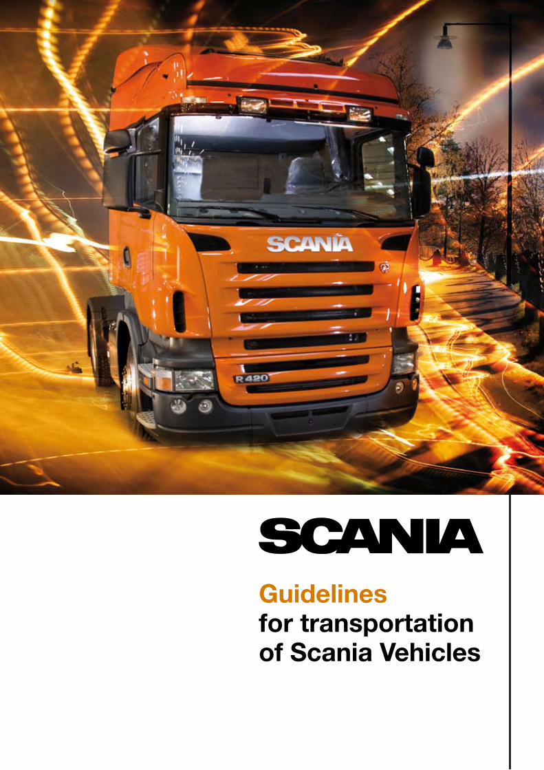
Content
Introduction…………………………… ……5
General Requirements………………… ……7
Pickup Routine ………………………………9 Checklist…………………………… …10
Driving…………………………………… …12 Groundclearence and Height Control…… …14 Gearing……………………………… …16 Transportation on own wheels……… ……18 Quick guide……………………………… …19
Lashing………………………………… …22
Parking and Storage…………………… …27
Towing………………………………… …28
24 hours assistance………………… ……29
Damage………………………………… ……30
Audit…………………………………… ……31

4
5
IntroductionThis booklet ”Guidelines for transportation of Scania Vehicles” is publishedby Scania CV AB and should always be taken into consideration by thecompanies and contractors appointed by Scania CV AB or its agentsprior handling or effect the movement of Scania Vehicles world wide.
Please note that the requirements according to the guidelines do not inany way supersede the regulations stipulated by law, conventions orvarious authorities.
These Guidelines contain such information of which the transporters must be aware about in order to handle and transport the vehicles, without causing damage during the transport, or during the time in which the transporter has the responsibility of the vehicles.
If problems do occur whilst the vehicles is in the transporters care, thisbooklet does not, and is not intended to substitute especially skilled personnel. Nor does it substitute relevant specialized literature and therefore we at these occasions encourage the transporter to contact nearest Scania 24-hour assistance.
The Guidelines set out in this booklet is due to that one of the Scania CV ABtop priorities are to ensure that our customer receives the high-end topquality as intended. This demand requires the transporters and contractorsto use such equipment and in such a manner that it meets up to this standard. The contracted party is responsible for ensuring that all involved personnel, including subcontractors and their personnel is notified and aware of these guidelines.
Our comprehensive guideline also contains several specific information of mechanical and electronically controlled equipment. The information herein must be considered to avoid unnecessary use of equipment.
The constant development of the vehicles, and the equipment that formthe vehicle require an awareness of the content in Guidelines, and howthese are handled in best manner to avoid unintentional damage to anypart that the vehicle may be equipped with.
We also by this emphasize the importance of ensuring to have accessto the latest edition of “Guidelines for Transportation of Scania Vehicles”.
This booklet is a 2009 year edition and it will be continuously updatedand available through internet for concerned transport companies andcontractors.
Regards Scania CV AB Publicum

6
7
General RequirementsThe terms and conditions set out below form the basis of contractualrequirements for companies appointed by Scania and / or its agents,when effecting the movement of Scania vehicles to the final delivery address.
The said terms and conditions are expressly intended to ensure, thatthe product is handled in proper manner and with understanding of that careless behavior, intended or unintended may cause severe damage. If a mechanical problem occur during transport contact Scania 24 hours Assistance and inform the next carrier.
While the vehicle is under the transporters responsibility, the drivermust exercise all due care to keep the chassis in ex factory conditions,meaning that the driver shall take the following responsibilities into consideration:
1. Drivers must complete all relevant equipment and safety checks prior to taking custody of a vehicles.
2. Driver must ensure to comply with the existing laws and regulations regarding dimensions.
3. No smoking in the cab, and the cab to be kept clean and free of litter.
4. It is not allowed to bring passengers during transport.
5. No unjustifiable interference with or improper use of electrical equipment, or any other components which form part of the vehicle.
6. No overweight use of the vehicle for sleeping or transport purposes, unless this is deemed an essential Scania requirement to execute the delivery to schedule and can be justified as such.
7. In the event of an electrical or mechanical breakdown of the vehicle, or in the event of the illumination of a warning light, abnormal noise, or any other abnormal audio or visual indication of a problem occurring, the driver must stop the vehicle immediately as safely as possible and call for assistance.
8. Drivers should at all times drive within applicable legal speed limits, and in a manner that is courteous and considerate to other road users.
In case of overnight stops or longer stops when delivering the vehicle, the vehicle has to be checked prior and before leaving the parking area. Park only in secure areas.
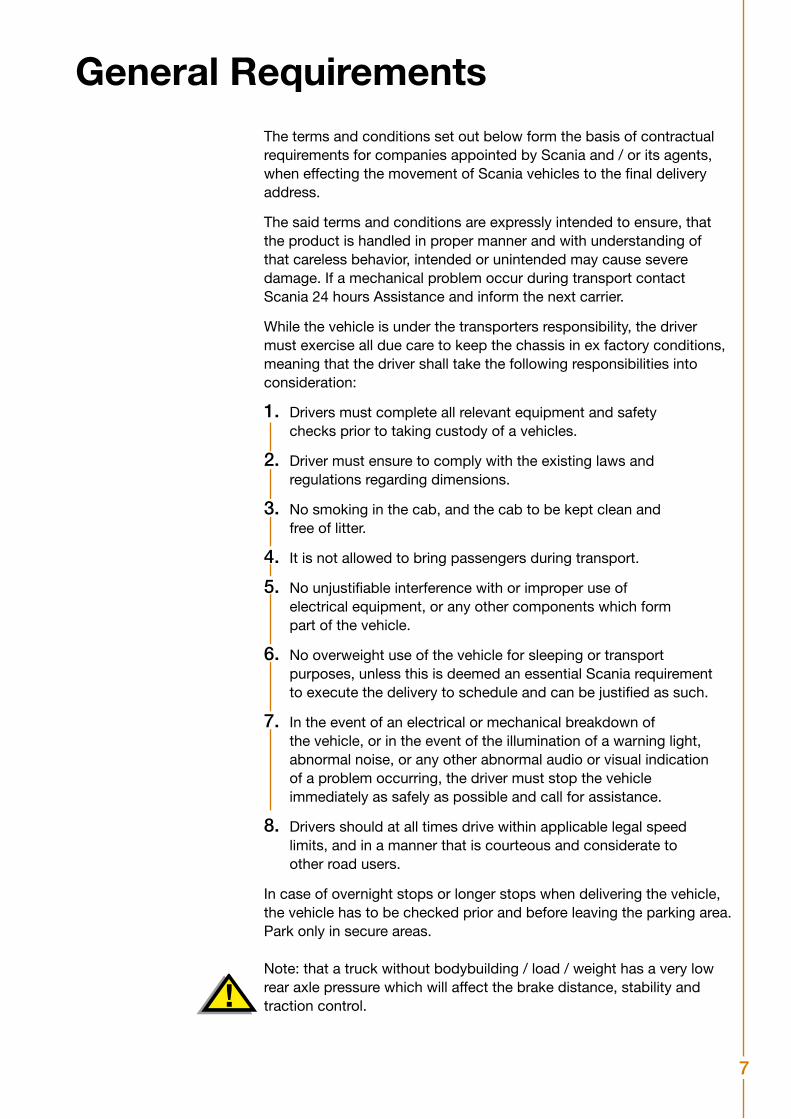
Note: that a truck without bodybuilding / load / weight has a very low rear axle pressure which will affect the brake distance, stability and traction control.
8
It is strictly forbidden • To write, remove or attach stickers upon the vehicles, unless Scania has explicitly authorized and clearly approved and indicated such areas.
• To detach or remove protection material such as seat protection.
Dismounting parts It is not allowed to dismount any parts. This said as a general ruling regarding the issue of dismounting parts. However, in the cases where the transporter consider the dismounting of some parts a necessity in order to perform the transport they must take contact with the Local Delivery Function for advisement and instructions.
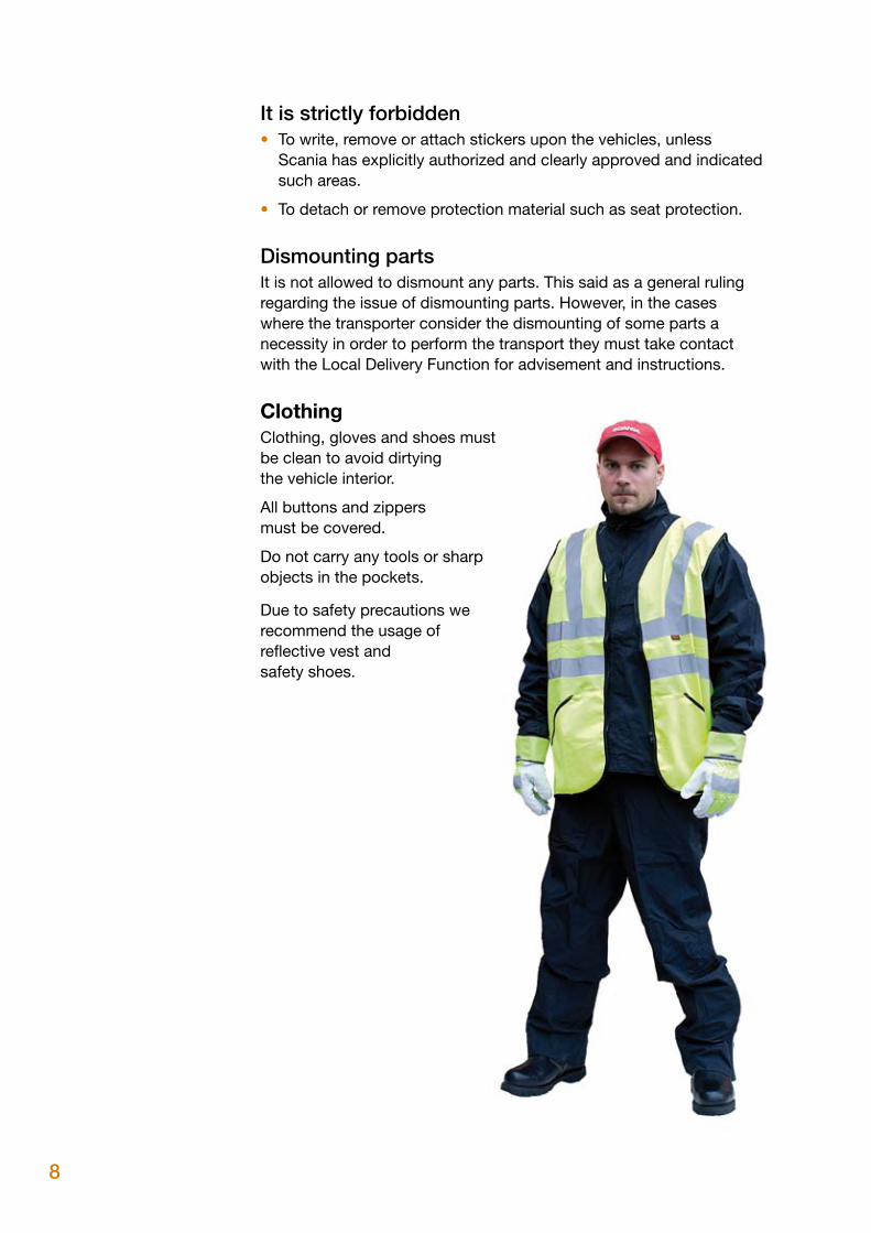
Clothing Clothing, gloves and shoes must be clean to avoid dirtying the vehicle interior.
All buttons and zippers must be covered.
Do not carry any tools or sharp objects in the pockets.
Due to safety precautions werecommend the usage ofreflective vest and safety shoes.
9
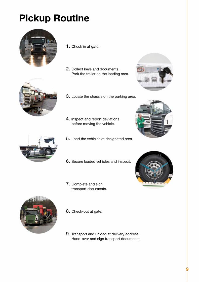
Pickup Routine
1. Check in at gate.
2. Collect keys and documents. Park the trailer on the loading area.
3. Locate the chassis on the parking area.
4. Inspect and report deviations before moving the vehicle.
5. Load the vehicles at designated area.
6. Secure loaded vehicles and inspect.
7. Complete and sign transport documents.
8. Check-out at gate.
9. Transport and unload at delivery address. Hand-over and sign transport documents.
10
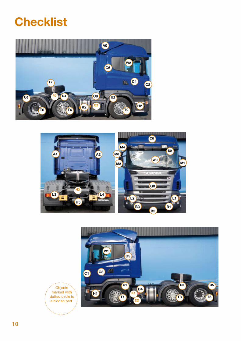
Checklist
W0
W1
C0
G0
L2
B3B2
B1
M1M2
M4S0
M6
L3
H5L1
L4
A2
C4
C6
C8
K2
C2
H1T1
EO
K1
U1
U6
T6
T3
U3
U4
T7
T4
T5
U5
U2
T2H2
C3
C5
C1
B4
A1
A0
E2
F0
H3
W2
Objects marked with
dotted circle is a hidden part.
11
Damaged Part CodesA0 Air deflector - roofA1 Air deflector - left sideA2 Air deflector - right sideB1 Bumper - left sideB2 Bumper - middle / underB3 Bumper - right sideB4 Battery boxC0 Cab - roofC1 Cab - Side spoiler - left sideC2 Cab - Side spoiler - right sideC3 Cab - Door - left sideC4 Cab - Door - right sideC5 Cab - left sideC6 Cab - right sideC7 Cab - Cover tool compartmentC8 CatwalkE0 Exhaust system - pipeE2 Exhaust system - silencerF0 Fifth wheelG0 Front grillH1 Front steps - left sideH2 Front steps - right side H3 ChassisH5 High pressure air connectors - rearK1 Air tanksK2 Fuel tanksL1 Lights front - left sideL2 Lights front - right sideL3 Lights rear - left sideL4 Lights rear - right sideM1 Mirror external - left sideM2 Mirror external - right side M4 Mirror external convex - right sideM6 Mirror auxilliary - right sideS0 Sun visorT1 Tire front - left sideT2 Tire front - right sideT3 Tires rear - left sideT4 Tires rear - right sideT5 Tires rear rear - left sideT6 Tires rear rear - right sideT7 Spare wheelU1 Mudguard front - left sideU2 Mudguard front - right sideU3 Mudguard rear - left sideU4 Mudguard rear - right sideU5 Mudguard rear rear - left sideU6 Mudguard rear rear - right side W0 Window frontW1 Window - left side W2 Window - right sideXX Other
Damage Codes0 Deviation within standards of acceptability1 Scratch small (up to 1 cm)2 Scratch long (bigger than 1cm)3 Cracked small (up to 1 cm)4 Cracked big (bigger than 1 cm)5 Broken6 Cut7 Dent8 Missing9 Factory fault10 Fire11 Water12 Other
12
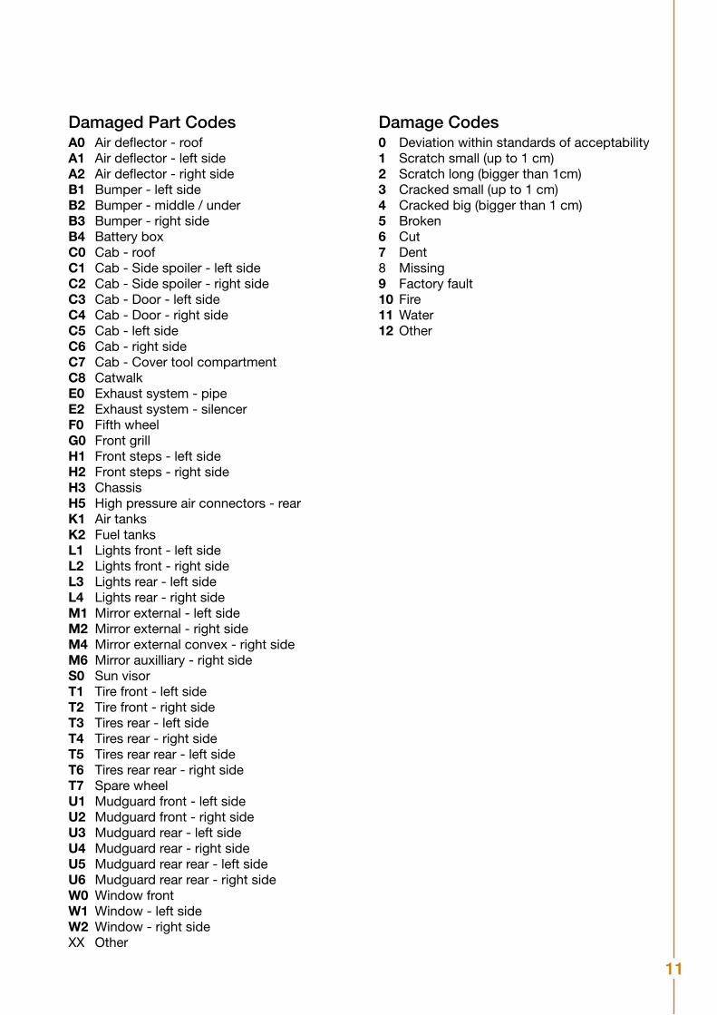
Vehicles may only by driven by personnel with valid driving licenses.
1. Switch on the main battery, located at the batterybox or on the rear left side on cab
2. Adjust the Steering wheel
a. Push the steering wheel adjustment button into the open position. For a few seconds it is possible to adjust the height and rake. Adjustment of the height is stepless.
There are 15 fixed driving positiones and one parking position for the rake.
b. Push the button into the locked position to lock the setting. The setting are also locked automatically after a few seconds.
The steering wheel should be angled into the parking position parallel with the floor only when the vehicle is parked.
Do not attempt to adjust the steering wheel while driving.
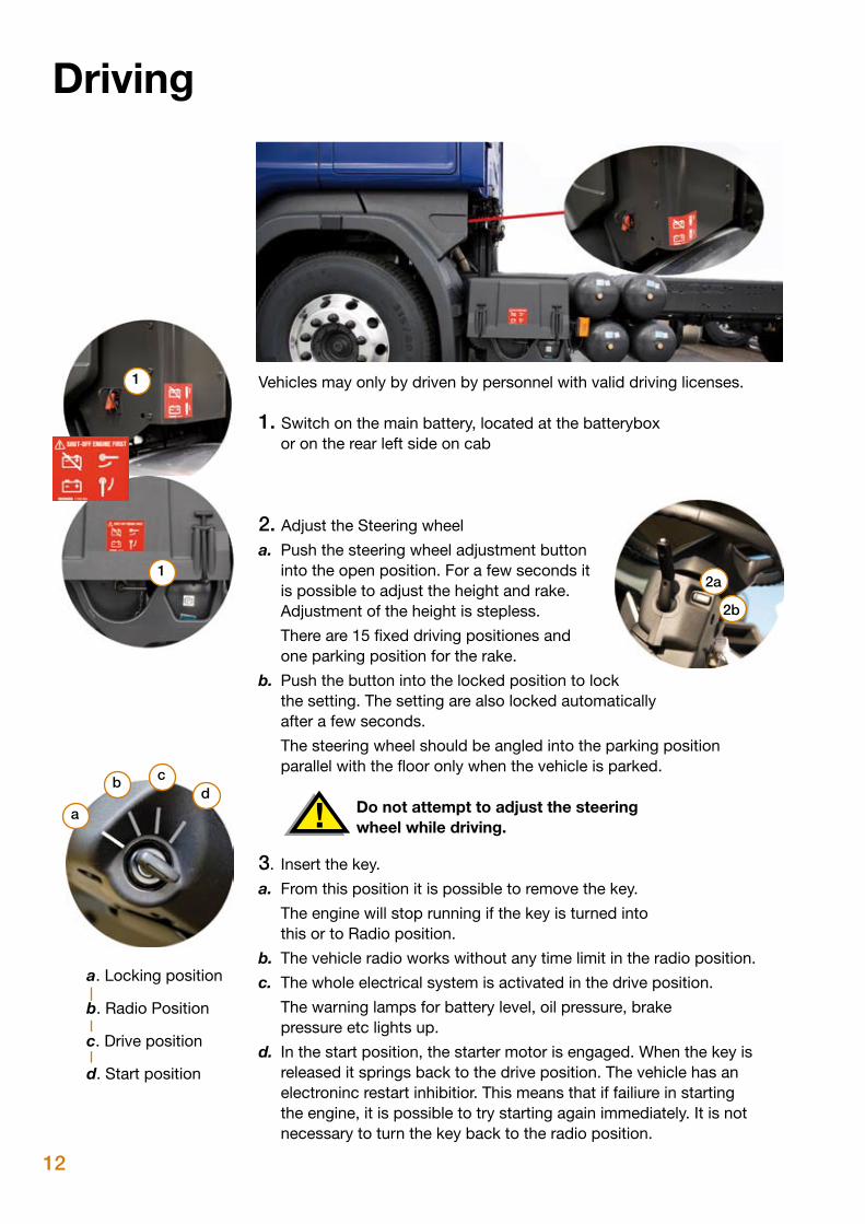
3. Insert the key.
a. From this position it is possible to remove the key.
The engine will stop running if the key is turned into this or to Radio position.
b. The vehicle radio works without any time limit in the radio position.
c. The whole electrical system is activated in the drive position.
The warning lamps for battery level, oil pressure, brake pressure etc lights up.
d. In the start position, the starter motor is engaged. When the key is released it springs back to the drive position. The vehicle has an electroninc restart inhibitior. This means that if failiure in starting the engine, it is possible to try starting again immediately. It is not necessary to turn the key back to the radio position.
a. Locking position
b. Radio Position
c. Drive position
d. Start position
a
b cd
1
12a
2b
Driving
13
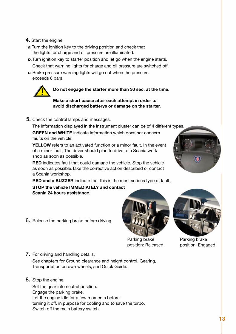
Parking brake position: Released.
Parking brake position: Engaged.
4. Start the engine.
a.Turn the ignition key to the driving position and check that the lights for charge and oil pressure are illuminated.
b. Turn ignition key to starter position and let go when the engine starts.
Check that warning lights for charge and oil pressure are switched off.
c. Brake pressure warning lights will go out when the pressure exceeds 6 bars.
Do not engage the starter more than 30 sec. at the time.
Make a short pause after each attempt in order to avoid discharged batterys or damage on the starter.
5. Check the control lamps and messages.
The information displayed in the instrument cluster can be of 4 different types.
GREEN and WHITE indicate information which does not concern faults on the vehicle.
YELLOW refers to an activated function or a minor fault. In the event of a minor fault, The driver should plan to drive to a Scania work shop as soon as possible.
RED indicates fault that could damage the vehicle. Stop the vehicle as soon as possible.Take the corrective action described or contact a Scania workshop.
RED and a BUZZER indicate that this is the most serious type of fault.
STOP the vehicle IMMEDIATELY and contact Scania 24 hours assistance.
6. Release the parking brake before driving.
7. For driving and handling details.
See chapters for Ground clearance and height control, Gearing, Transportation on own wheels, and Quick Guide.
8. Stop the engine.
Set the gear into neutral position. Engage the parking brake. Let the engine idle for a few moments before turning it off, in purpose for cooling and to save the turbo. Switch off the main battery switch.
14
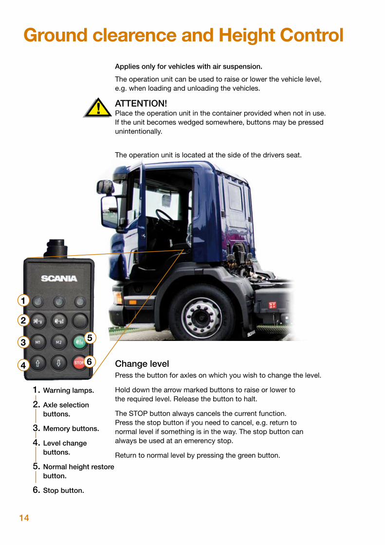
Ground clearence and Height ControlApplies only for vehicles with air suspension.
The operation unit can be used to raise or lower the vehicle level, e.g. when loading and unloading the vehicles.
ATTENTION! Place the operation unit in the container provided when not in use. If the unit becomes wedged somewhere, buttons may be pressed unintentionally.
The operation unit is located at the side of the drivers seat.
Change levelPress the button for axles on which you wish to change the level.
Hold down the arrow marked buttons to raise or lower to the required level. Release the button to halt.
The STOP button always cancels the current function. Press the stop button if you need to cancel, e.g. return to normal level if something is in the way. The stop button can always be used at an emerency stop.
Return to normal level by pressing the green button.
1. Warning lamps.
2. Axle selection buttons.
3. Memory buttons.
4. Level change buttons.
5. Normal height restore button.
6. Stop button.
1
2
3 5
4 6
15
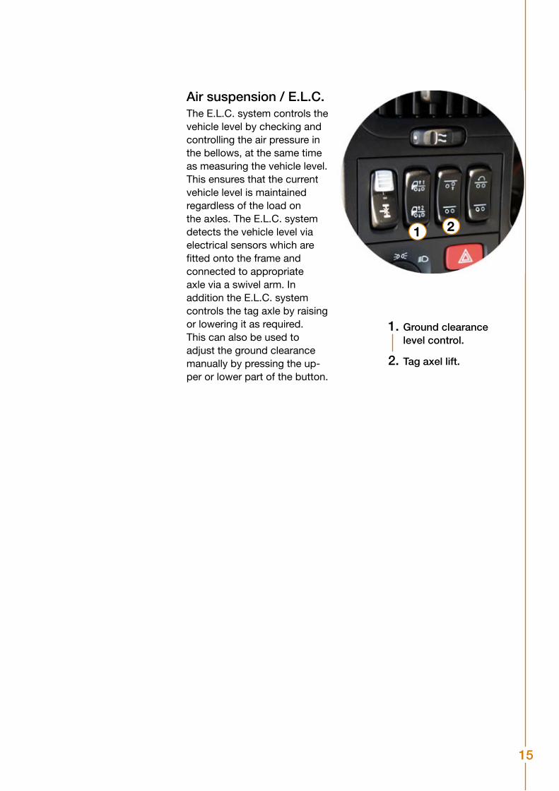
Air suspension / E.L.C.The E.L.C. system controls the vehicle level by checking and controlling the air pressure in the bellows, at the same time as measuring the vehicle level. This ensures that the current vehicle level is maintained regardless of the load on the axles. The E.L.C. system detects the vehicle level via electrical sensors which are fitted onto the frame and connected to appropriate axle via a swivel arm. In addition the E.L.C. system controls the tag axle by raising or lowering it as required.This can also be used to adjust the ground clearance manually by pressing the up-per or lower part of the button.
1. Ground clearance level control.
2. Tag axel lift.
1 2
16
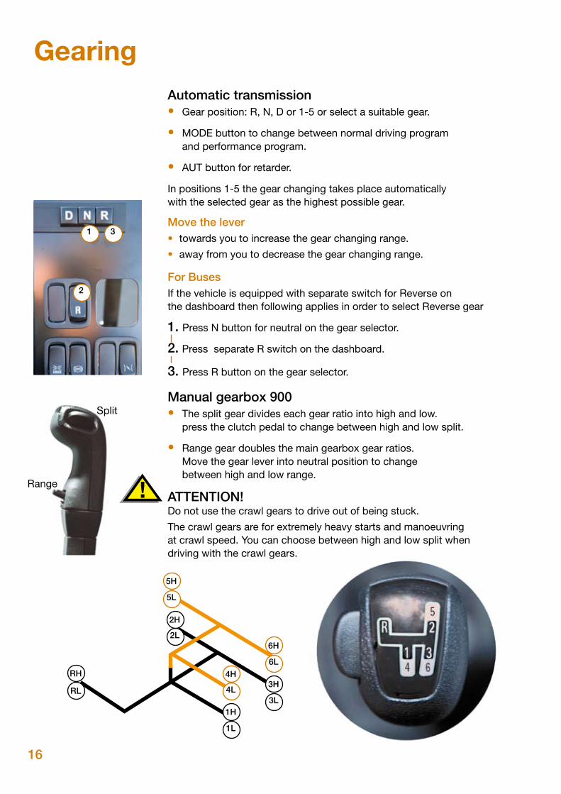
GearingAutomatic transmission• Gear position: R, N, D or 1-5 or select a suitable gear.
• MODE button to change between normal driving program and performance program.
• AUT button for retarder.
In positions 1-5 the gear changing takes place automatically with the selected gear as the highest possible gear.
Move the lever• towards you to increase the gear changing range.
• away from you to decrease the gear changing range.
For BusesIf the vehicle is equipped with separate switch for Reverse on the dashboard then following applies in order to select Reverse gear
1. Press N button for neutral on the gear selector.
2. Press separate R switch on the dashboard.
3. Press R button on the gear selector.
Manual gearbox 900• The split gear divides each gear ratio into high and low. press the clutch pedal to change between high and low split.
• Range gear doubles the main gearbox gear ratios. Move the gear lever into neutral position to change between high and low range.
ATTENTION! Do not use the crawl gears to drive out of being stuck.
The crawl gears are for extremely heavy starts and manoeuvringat crawl speed. You can choose between high and low split whendriving with the crawl gears.
6L
3L
6H
3H
5L
2L
5H
2H
RL
RH
4L
1L
4H
1H
1 3
2
Split
Range
17
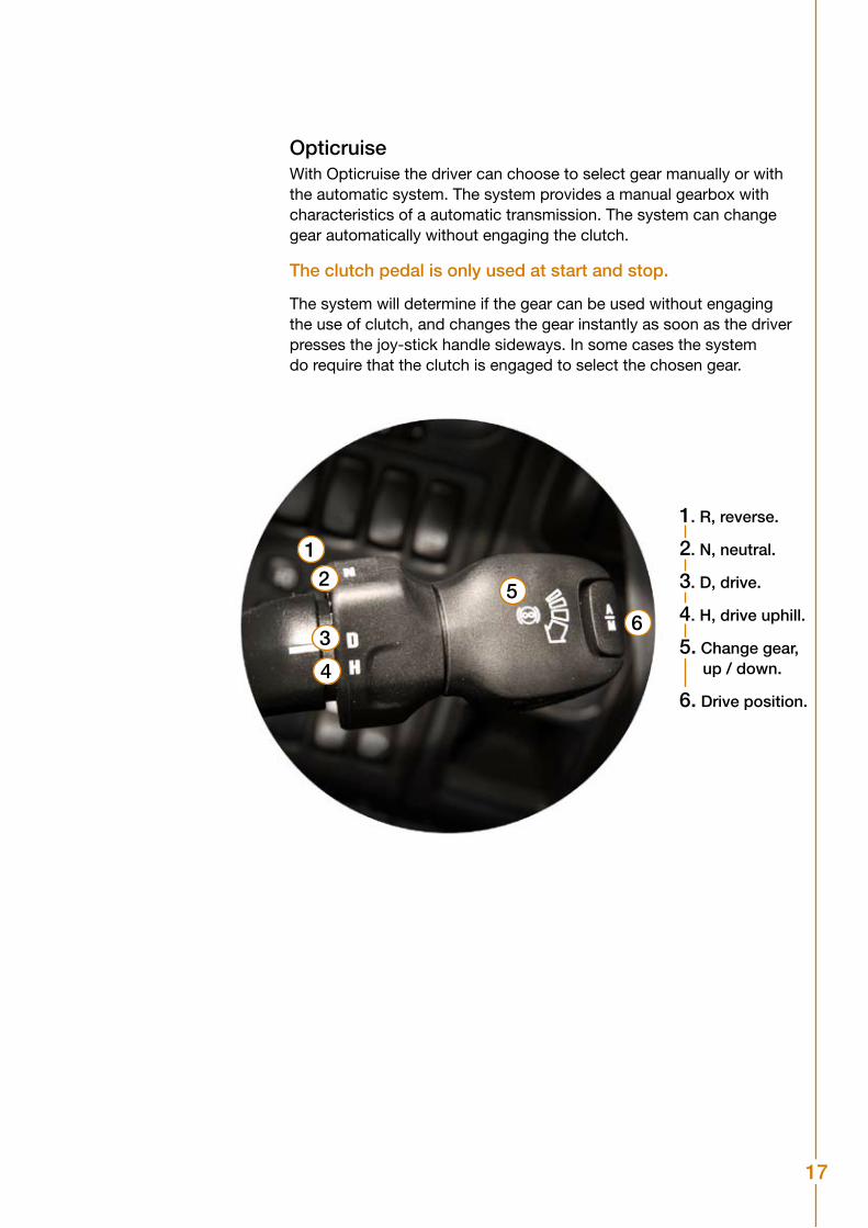
OpticruiseWith Opticruise the driver can choose to select gear manually or withthe automatic system. The system provides a manual gearbox withcharacteristics of a automatic transmission. The system can change gear automatically without engaging the clutch.
The clutch pedal is only used at start and stop.
The system will determine if the gear can be used without engaging the use of clutch, and changes the gear instantly as soon as the driver presses the joy-stick handle sideways. In some cases the system do require that the clutch is engaged to select the chosen gear.
21
3
4
5
6
1. R, reverse.
2. N, neutral.
3. D, drive.
4. H, drive uphill.
5. Change gear, up / down.
6. Drive position.
18
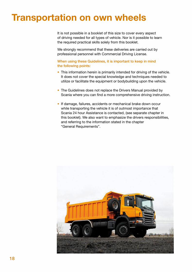
Transportation on own wheelsIt is not possible in a booklet of this size to cover every aspect of driving needed for all types of vehicle. Nor is it possible to learnthe required practical skills solely from this booklet.
We strongly recommend that these deliveries are carried out by professional personnel with Commercial Driving License.
When using these Guidelines, it is important to keep in mind the following points:
• This information herein is primarily intended for driving of the vehicle. It does not cover the special knowledge and techniques needed to utilize or facilitate the equipment or bodybuilding upon the vehicle.
• The Guidelines does not replace the Drivers Manual provided by Scania where you can find a more comprehensive driving instruction.
• If damage, failures, accidents or mechanical brake down occur while transporting the vehicle it is of outmost importance that Scania 24 hour Assistance is contacted, (see separate chapter in this booklet). We also want to emphasize the drivers responsibilities, and referring to the information stated in the chapter “General Requirements”.
19
1
2
34
56
89
9
1213
14
1 2 3 4 5
6 7
2
6
13
5
89
7
4
12 3 5
4
2 4 6 8
1 3 5 7
1
23
1
2
3
4
91
11
1
2
3
4
12
34
5
98
76
10
710
12
34
5
67
8
Vehi
cle
info
rmat
ion
Switc
hes
and
cont
rols
Load
tran
sfer
Impo
rtan
t! St
art t
he v
ehic
le c
aref
ully
afte
r loa
d tra
nsfe
rs o
f mor
e th
an 1
3 to
nnes
.Sp
eed
mus
t not
exc
eed
30 k
m/h
to e
nabl
e a
load
tran
sfer
. Eng
age
the
diffe
rent
ial l
ock
for t
he
bogi
e w
hen
carry
ing
out a
load
tran
sfer
on
a ve
hicl
e w
ith ta
ndem
bog
ie. I
nfor
mat
ion
on th
e di
strib
utio
n of
the
load
is s
how
n in
the
inst
rum
ent c
lust
er.
Use
a s
hort
pres
s on
:th
e up
per s
ectio
n of
the
switc
h to
car
ry o
ut a
load
tran
sfer
that
incr
ease
s ha
lf sh
aft l
oad
by
30%
.th
e lo
wer
sec
tion
of th
e sw
itch
to s
top
the
load
tran
sfer
.
Man
ual l
oad
tran
sfer
Keep
the
switc
h de
pres
sed
in:
uppe
r pos
ition
to s
tart
or in
crea
se th
e lo
ad tr
ansf
er.
low
er p
ositi
on to
redu
ce th
e lo
ad tr
ansf
er.
low
er p
ositio
n fo
r a s
hort
time
to s
top
the
load
tran
sfer
.
• • • • •
Switc
hes
Flas
her a
nd w
iper
leve
r
Adj
ustin
g tim
e an
d in
stru
men
t lig
htin
gC
hang
e th
e se
tting
s us
ing
the
butto
ns fo
r the
dis
play
.M
ove
the
rota
ry c
ontro
l for
the
head
lam
ps to
the
dipp
ed
beam
pos
ition
to c
hang
e th
e se
tting
s fo
r the
inst
rum
ent
light
ing.
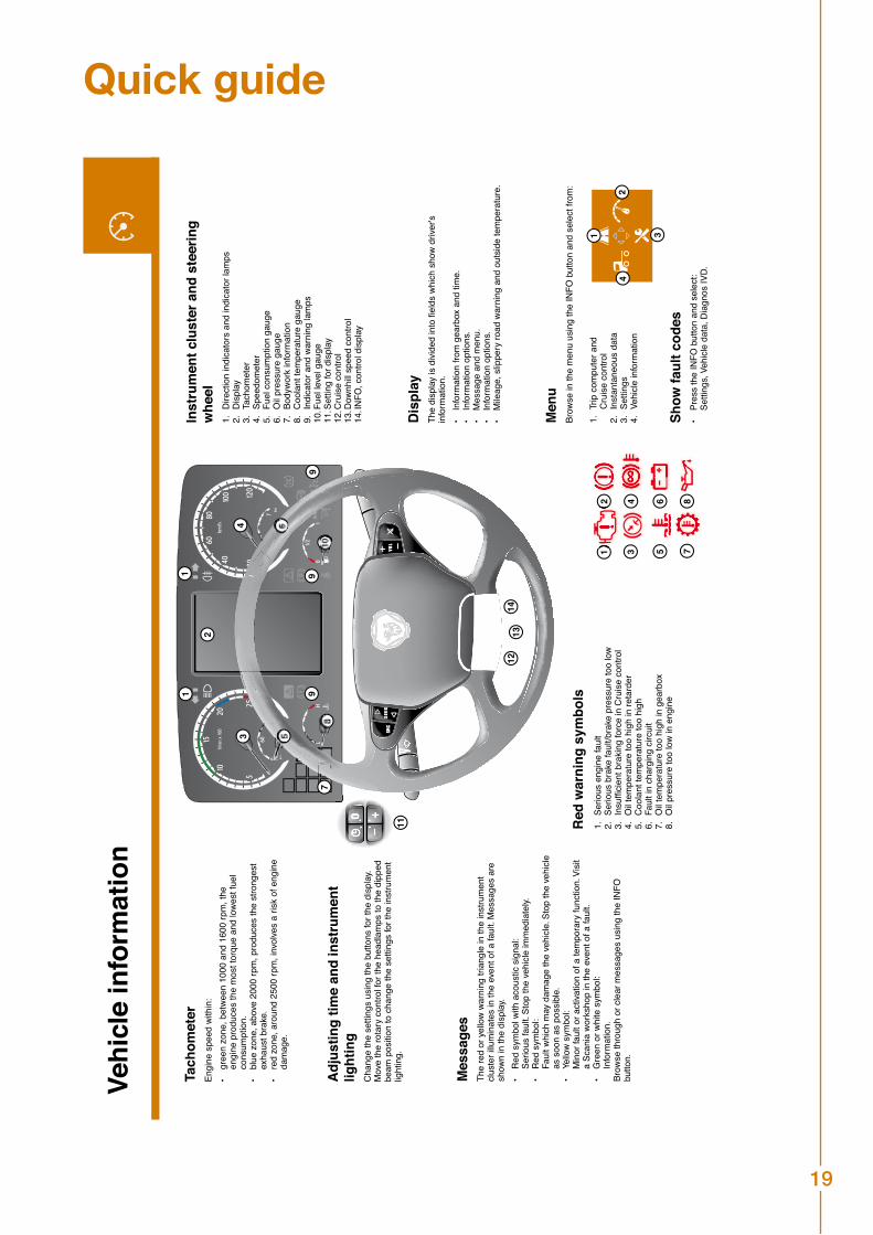
Tach
omet
erEn
gine
spe
ed w
ithin
:gr
een
zone
, bet
wee
n 10
00 a
nd 1
600
rpm
, the
en
gine
pro
duce
s th
e m
ost t
orqu
e an
d lo
wes
t fue
l co
nsum
ptio
n.bl
ue z
one,
abo
ve 2
000
rpm
, pro
duce
s th
e st
rong
est
exha
ust b
rake
.re
d zo
ne, a
roun
d 25
00 rp
m, i
nvol
ves
a ris
k of
eng
ine
dam
age.
• • • Mes
sage
sTh
e re
d or
yel
low
war
ning
tria
ngle
in th
e in
stru
men
t cl
uste
r illu
min
ates
in th
e ev
ent o
f a fa
ult.
Mes
sage
s ar
e sh
own
in th
e di
spla
y. R
ed s
ymbo
l with
aco
ustic
sig
nal:
Se
rious
faul
t. St
op th
e ve
hicl
e im
med
iate
ly.
Red
sym
bol:
Fa
ult w
hich
may
dam
age
the
vehi
cle.
Sto
p th
e ve
hicl
e as
soo
n as
pos
sibl
e.
Yello
w s
ymbo
l:
Min
or fa
ult o
r act
ivatio
n of
a te
mpo
rary
func
tion.
Vis
it a
Scan
ia w
orks
hop
in th
e ev
ent o
f a fa
ult.
Gre
en o
r whi
te s
ymbo
l:
Info
rmat
ion.
Brow
se th
roug
h or
cle
ar m
essa
ges
usin
g th
e IN
FO
butto
n.
• • • •
Red
war
ning
sym
bols
Serio
us e
ngin
e fa
ult
Serio
us b
rake
faul
t/bra
ke p
ress
ure
too
low
Insu
ffici
ent b
raki
ng fo
rce
in C
ruis
e co
ntro
lO
il te
mpe
ratu
re to
o hi
gh in
reta
rder
Coo
lant
tem
pera
ture
too
high
Faul
t in
char
ging
circ
uit
Oil
tem
pera
ture
too
high
in g
earb
oxO
il pr
essu
re to
o lo
w in
eng
ine
1. 2. 3. 4. 5. 6. 7. 8.
Dis
play
The
disp
lay
is d
ivid
ed in
to fi
elds
whi
ch s
how
driv
er's
info
rmat
ion.
Info
rmat
ion
from
gea
rbox
and
tim
e.In
form
atio
n op
tions
.M
essa
ge a
nd m
enu.
In
form
atio
n op
tions
.M
ileag
e, s
lippe
ry ro
ad w
arni
ng a
nd o
utsi
de te
mpe
ratu
re.
• • • • •Inst
rum
ent c
lust
er a
nd s
teer
ing
whe
elD
irect
ion
indi
cato
rs a
nd in
dica
tor l
amps
D
ispl
ayTa
chom
eter
Spee
dom
eter
Fu
el c
onsu
mpt
ion
gaug
e O
il pr
essu
re g
auge
Body
wor
k in
form
atio
n
Coo
lant
tem
pera
ture
gau
ge
Indi
cato
r and
war
ning
lam
ps
Fuel
leve
l gau
geSe
tting
for d
ispl
ayC
ruis
e co
ntro
l
Dow
nhill
spee
d co
ntro
l
INFO
, con
trol d
ispl
ay
1. 2. 3. 4. 5. 6. 7. 8. 9. 10.
11.
12.
13.
14.
Men
uBr
owse
in th
e m
enu
usin
g th
e IN
FO b
utto
n an
d se
lect
from
:
Trip
com
pute
r and
C
ruis
e co
ntro
l In
stan
tane
ous
data
Setti
ngs
Vehi
cle
info
rmat
ion
1. 2. 3. 4. Show
faul
t cod
esPr
ess
the
INFO
but
ton
and
sele
ct:
Setti
ngs,
Veh
icle
dat
a, D
iagn
os IV
D.•
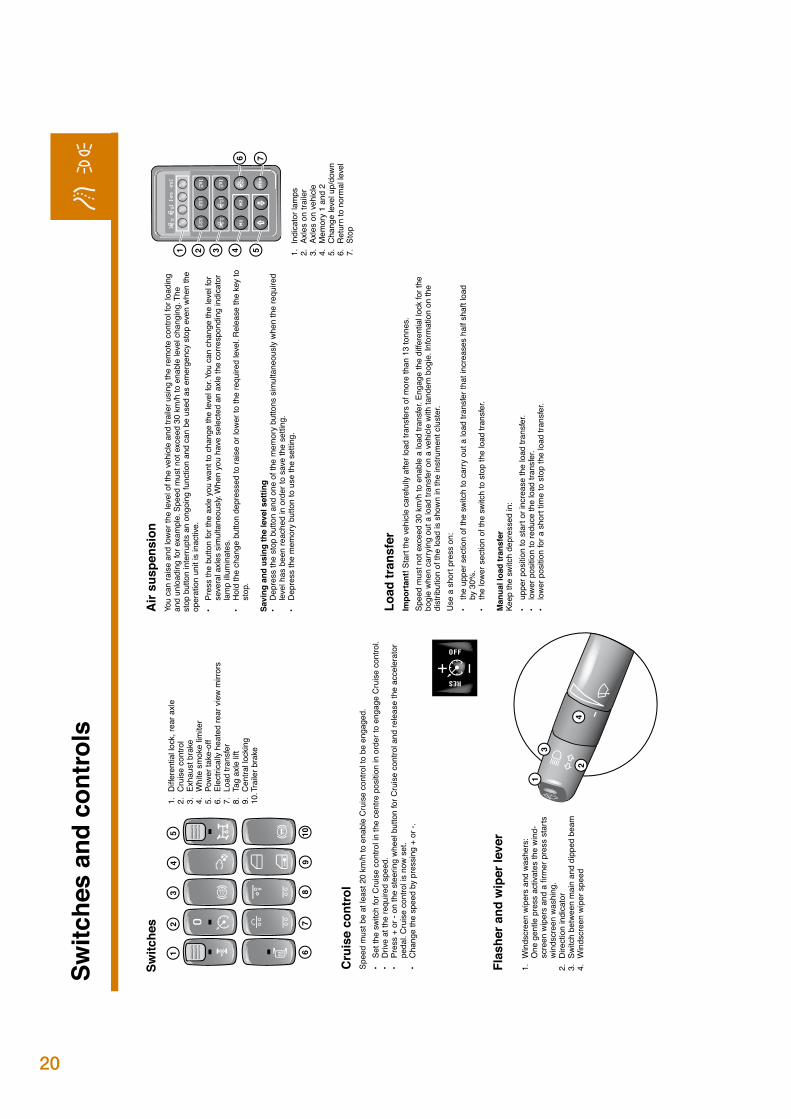
Win
dscr
een
wip
ers
and
wash
ers:
O
ne g
entle
pre
ss a
ctiva
tes
the
win
d-sc
reen
wip
ers
and
a fir
mer
pre
ss s
tarts
w
inds
cree
n wa
shin
g.D
irect
ion
indi
cato
rSw
itch
betw
een
mai
n an
d di
pped
bea
mW
inds
cree
n w
iper
spe
ed
1. 2. 3. 4.Cru
ise
cont
rol
Spee
d m
ust b
e at
leas
t 20
km/h
to e
nabl
e C
ruis
e co
ntro
l to
be e
ngag
ed.
Set t
he s
witc
h fo
r Cru
ise
cont
rol i
n th
e ce
ntre
pos
ition
in o
rder
to e
ngag
e C
ruis
e co
ntro
l.D
rive
at th
e re
quire
d sp
eed.
Pres
s +
or -
on th
e st
eerin
g w
heel
but
ton
for C
ruis
e co
ntro
l and
rele
ase
the
acce
lera
tor
peda
l. C
ruis
e co
ntro
l is
now
set
. C
hang
e th
e sp
eed
by p
ress
ing
+ or
-.
• • • •
Diff
eren
tial l
ock,
rear
axl
eC
ruis
e co
ntro
lEx
haus
t bra
keW
hite
sm
oke
limite
rPo
wer
take
-off
Elec
trica
lly h
eate
d re
ar v
iew
mirr
ors
Load
tran
sfer
Tag
axle
lift
Cen
tral l
ocki
ngTr
aile
r bra
ke
1. 2. 3. 4. 5. 6. 7. 8. 9. 10.
Air
susp
ensi
onYo
u ca
n ra
ise
and
low
er th
e le
vel o
f the
veh
icle
and
trai
ler u
sing
the
rem
ote
cont
rol f
or lo
adin
g an
d un
load
ing
for e
xam
ple.
Spe
ed m
ust n
ot e
xcee
d 30
km
/h to
ena
ble
leve
l cha
ngin
g. T
he
stop
but
ton
inte
rrupt
s an
ong
oing
func
tion
and
can
be u
sed
as e
mer
genc
y st
op e
ven
whe
n th
e op
erat
ion
unit
is in
activ
e.Pr
ess
the
butto
n fo
r the
axl
e yo
u wa
nt to
cha
nge
the
leve
l for
. You
can
cha
nge
the
leve
l for
se
vera
l axl
es s
imul
tane
ously
. Whe
n yo
u ha
ve s
elec
ted
an a
xle
the
corre
spon
ding
indi
cato
r la
mp
illum
inat
es.
Hol
d th
e ch
ange
but
ton
depr
esse
d to
rais
e or
low
er to
the
requ
ired
leve
l. R
elea
se th
e ke
y to
st
op.
Savi
ng a
nd u
sing
the
leve
l set
ting
Dep
ress
the
stop
but
ton
and
one
of th
e m
emor
y bu
ttons
sim
ulta
neou
sly
whe
n th
e re
quire
d le
vel h
as b
een
reac
hed
in o
rder
to s
ave
the
setti
ng.
Dep
ress
the
mem
ory
butto
n to
use
the
setti
ng.
• • • •In
dica
tor l
amps
Axle
s on
trai
ler
Axle
s on
veh
icle
Mem
ory
1 an
d 2
Cha
nge
leve
l up/
dow
nR
etur
n to
nor
mal
leve
lSt
op
1. 2. 3. 4. 5. 6. 7.
Driv
er e
nviro
nmen
tLo
cks
and
alar
m s
yste
m
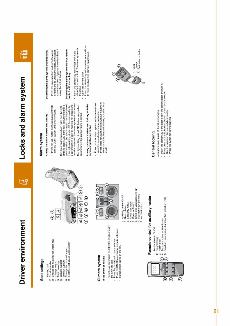
Arm
ing
the
alar
m s
yste
m a
nd lo
ckin
g
Pres
s th
e lo
ck b
utto
n on
the
rem
ote
cont
rol t
o ar
m th
e al
arm
sys
tem
and
lock
the
door
s.
The
dire
ctio
n in
dica
tors
flas
h tw
ice
and
the
light
-em
ittin
g di
ode
LED
in th
e ro
of is
illu
min
ated
for 5
se
cond
s w
hen
the
alar
m s
yste
m h
as b
een
arm
ed.
If th
e lig
ht-e
mitt
ing
diod
e LE
D fl
ashe
s qu
ickly
for
5 se
cond
s th
en a
doo
r or h
atch
is n
ot c
lose
d an
d re
mai
ns u
nloc
ked.
The
ala
rm s
yste
m is
stil
l arm
ed.
The
light
-em
ittin
g di
ode
LED
flas
hes
ever
y ot
her
seco
nd w
hen
the
alar
m s
yste
m is
arm
ed.
Arm
ing
the
alar
m s
yste
m a
nd lo
ckin
g w
ith th
e pe
rimet
er p
rote
ctio
n bu
tton
Pres
s on
ce fo
r ala
rm s
yste
m w
ithou
t mov
emen
t de
tect
or, s
o-ca
lled
perim
eter
pro
tect
ion.
Pres
s tw
ice
for a
larm
sys
tem
with
out m
ovem
ent
dete
ctor
and
incl
inat
ion
indi
cato
r, so
-cal
led
ferry
m
ode.
• • • Cen
tral
lock
ing
Lock
and
unl
ock
in o
ne o
f the
follo
win
g wa
ys:
Inse
rt th
e st
arte
r key
in th
e do
or lo
ck in
the
drive
r's d
oor a
nd tu
rn it
.Pr
ess
once
on
the
lock
/unl
ock
butto
n on
the
rem
ote
cont
rol.
Use
the
catc
h on
the
inte
rnal
doo
r han
dle.
Pres
s th
e sw
itch
for c
entra
l loc
king
.
• • • •
Rem
ote
cont
rol f
or a
uxili
ary
heat
erAu
xilia
ry h
eate
r On/
Off
Prog
ram
min
g Al
arm
clo
ckSn
ooze
func
tion
for 1
0 m
inut
esSc
roll
up (+
) or d
own
(-) a
nd c
onfir
m s
elec
tion
(OK)
.
1. 2. 3. 4. 5.
Clim
ate
syst
emIn
the
even
t of m
istin
g
Turn
the
air d
istri
butio
n to
def
rost
er p
ositi
on to
dry
th
e ai
r in
the
cab.
Pres
s R
ecirc
ulat
ion
in d
amp
wea
ther
.Pr
ess
ECO
N if
the
econ
omy
mod
e is
act
ivate
d.Se
lect
a h
igh
spee
d on
the
fan.
• • • •Au
xilia
ry h
eate
r On/
Off
Rec
ircul
atio
n Ec
onom
y m
ode
Clo
se ro
of h
atch
Ope
n ro
of h
atch
Shor
t-sto
p ve
ntila
tion
and
fan
Setti
ng th
e te
mpe
ratu
reAi
r dis
tribu
tion
1. 2. 3. 4. 5. 6. 7. 8.
Hea
ting
pad
Shoc
k ab
sorb
er
Cha
nge
the
angl
e fo
r the
who
le s
eat
Cha
nge
heig
htR
apid
lowe
ring
Lum
bar s
uppo
rtLu
mba
r sup
port
Cha
nge
the
back
rest
ang
leSh
ift th
e se
at s
quab
long
itudi
nally
1. 2. 3. 4. 5. 6. 7. 8. 9.Seat
set
tings
Dis
arm
ing
the
alar
m s
yste
m a
nd u
nloc
king
Pres
s th
e un
lock
but
ton
to d
isar
m th
e al
arm
sy
stem
and
to u
nloc
k th
e do
ors.
If th
e al
arm
sy
stem
has
bee
n tri
gger
ed th
en d
eact
ivate
it
usin
g th
e un
lock
but
ton.
Dis
arm
ing
the
alar
m s
yste
m w
ithou
t rem
ote
cont
rol w
ith s
tart
er k
ey
Inse
rt th
e st
arte
r key
in th
e do
or lo
ck in
the
drive
r's d
oor a
nd u
nloc
k. T
he a
larm
sys
tem
is
trigg
ered
.O
pen
the
drive
r's d
oor.
Inse
rt th
e st
arte
r key
in th
e st
arte
r loc
k an
d tu
rn
to d
rive
posi
tion.
The
ala
rm is
dea
ctiva
ted.
• • • •
Lock
Unl
ock
Perim
eter
pro
tect
ion
1. 2. 3.
Ala
rm s
yste
m
Quick guide
20
1
2
34
56
89
9
1213
14
1 2 3 4 5
6 7
2
6
13
5
89
7
4
12 3 5
4
2 4 6 8
1 3 5 7
1
23
1
2
3
4
91
11
1
2
3
4
12
34
5
98
76
10
710
12
34
5
67
8
Vehi
cle
info
rmat
ion
Switc
hes
and
cont
rols
Load
tran
sfer
Impo
rtan
t! St
art t
he v
ehic
le c
aref
ully
afte
r loa
d tra
nsfe
rs o
f mor
e th
an 1
3 to
nnes
.Sp
eed
mus
t not
exc
eed
30 k
m/h
to e
nabl
e a
load
tran
sfer
. Eng
age
the
diffe
rent
ial l
ock
for t
he
bogi
e w
hen
carry
ing
out a
load
tran
sfer
on
a ve
hicl
e w
ith ta
ndem
bog
ie. I
nfor
mat
ion
on th
e di
strib
utio
n of
the
load
is s
how
n in
the
inst
rum
ent c
lust
er.
Use
a s
hort
pres
s on
:th
e up
per s
ectio
n of
the
switc
h to
car
ry o
ut a
load
tran
sfer
that
incr
ease
s ha
lf sh
aft l
oad
by
30%
.th
e lo
wer
sec
tion
of th
e sw
itch
to s
top
the
load
tran
sfer
.
Man
ual l
oad
tran
sfer
Keep
the
switc
h de
pres
sed
in:
uppe
r pos
ition
to s
tart
or in
crea
se th
e lo
ad tr
ansf
er.
low
er p
ositi
on to
redu
ce th
e lo
ad tr
ansf
er.
low
er p
ositio
n fo
r a s
hort
time
to s
top
the
load
tran
sfer
.
• • • • •
Switc
hes
Flas
her a
nd w
iper
leve
r
Adj
ustin
g tim
e an
d in
stru
men
t lig
htin
gC
hang
e th
e se
tting
s us
ing
the
butto
ns fo
r the
dis
play
.M
ove
the
rota
ry c
ontro
l for
the
head
lam
ps to
the
dipp
ed
beam
pos
ition
to c
hang
e th
e se
tting
s fo
r the
inst
rum
ent
light
ing.
Tach
omet
erEn
gine
spe
ed w
ithin
:gr
een
zone
, bet
wee
n 10
00 a
nd 1
600
rpm
, the
en
gine
pro
duce
s th
e m
ost t
orqu
e an
d lo
wes
t fue
l co
nsum
ptio
n.bl
ue z
one,
abo
ve 2
000
rpm
, pro
duce
s th
e st
rong
est
exha
ust b
rake
.re
d zo
ne, a
roun
d 25
00 rp
m, i
nvol
ves
a ris
k of
eng
ine
dam
age.
• • • Mes
sage
sTh
e re
d or
yel
low
war
ning
tria
ngle
in th
e in
stru
men
t cl
uste
r illu
min
ates
in th
e ev
ent o
f a fa
ult.
Mes
sage
s ar
e sh
own
in th
e di
spla
y. R
ed s
ymbo
l with
aco
ustic
sig
nal:
Se
rious
faul
t. St
op th
e ve
hicl
e im
med
iate
ly.
Red
sym
bol:
Fa
ult w
hich
may
dam
age
the
vehi
cle.
Sto
p th
e ve
hicl
e as
soo
n as
pos
sibl
e.
Yello
w s
ymbo
l:
Min
or fa
ult o
r act
ivatio
n of
a te
mpo
rary
func
tion.
Vis
it a
Scan
ia w
orks
hop
in th
e ev
ent o
f a fa
ult.
Gre
en o
r whi
te s
ymbo
l:
Info
rmat
ion.
Brow
se th
roug
h or
cle
ar m
essa
ges
usin
g th
e IN
FO
butto
n.
• • • •
Red
war
ning
sym
bols
Serio
us e
ngin
e fa
ult
Serio
us b
rake
faul
t/bra
ke p
ress
ure
too
low
Insu
ffici
ent b
raki
ng fo
rce
in C
ruis
e co
ntro
lO
il te
mpe
ratu
re to
o hi
gh in
reta
rder
Coo
lant
tem
pera
ture
too
high
Faul
t in
char
ging
circ
uit
Oil
tem
pera
ture
too
high
in g
earb
oxO
il pr
essu
re to
o lo
w in
eng
ine
1. 2. 3. 4. 5. 6. 7. 8.
Dis
play
The
disp
lay
is d
ivid
ed in
to fi
elds
whi
ch s
how
driv
er's
info
rmat
ion.
Info
rmat
ion
from
gea
rbox
and
tim
e.In
form
atio
n op
tions
.M
essa
ge a
nd m
enu.
In
form
atio
n op
tions
.M
ileag
e, s
lippe
ry ro
ad w
arni
ng a
nd o
utsi
de te
mpe
ratu
re.
• • • • •Inst
rum
ent c
lust
er a
nd s
teer
ing
whe
elD
irect
ion
indi
cato
rs a
nd in
dica
tor l
amps
D
ispl
ayTa
chom
eter
Spee
dom
eter
Fu
el c
onsu
mpt
ion
gaug
e O
il pr
essu
re g
auge
Body
wor
k in
form
atio
n
Coo
lant
tem
pera
ture
gau
ge
Indi
cato
r and
war
ning
lam
ps
Fuel
leve
l gau
geSe
tting
for d
ispl
ayC
ruis
e co
ntro
l
Dow
nhill
spee
d co
ntro
l
INFO
, con
trol d
ispl
ay
1. 2. 3. 4. 5. 6. 7. 8. 9. 10.
11.
12.
13.
14.
Men
uBr
owse
in th
e m
enu
usin
g th
e IN
FO b
utto
n an
d se
lect
from
:
Trip
com
pute
r and
C
ruis
e co
ntro
l In
stan
tane
ous
data
Setti
ngs
Vehi
cle
info
rmat
ion
1. 2. 3. 4. Show
faul
t cod
esPr
ess
the
INFO
but
ton
and
sele
ct:
Setti
ngs,
Veh
icle
dat
a, D
iagn
os IV
D.•
Win
dscr
een
wip
ers
and
wash
ers:
O
ne g
entle
pre
ss a
ctiva
tes
the
win
d-sc
reen
wip
ers
and
a fir
mer
pre
ss s
tarts
w
inds
cree
n wa
shin
g.D
irect
ion
indi
cato
rSw
itch
betw
een
mai
n an
d di
pped
bea
mW
inds
cree
n w
iper
spe
ed
1. 2. 3. 4.Cru
ise
cont
rol
Spee
d m
ust b
e at
leas
t 20
km/h
to e
nabl
e C
ruis
e co
ntro
l to
be e
ngag
ed.
Set t
he s
witc
h fo
r Cru
ise
cont
rol i
n th
e ce
ntre
pos
ition
in o
rder
to e
ngag
e C
ruis
e co
ntro
l.D
rive
at th
e re
quire
d sp
eed.
Pres
s +
or -
on th
e st
eerin
g w
heel
but
ton
for C
ruis
e co
ntro
l and
rele
ase
the
acce
lera
tor
peda
l. C
ruis
e co
ntro
l is
now
set
. C
hang
e th
e sp
eed
by p
ress
ing
+ or
-.
• • • •
Diff
eren
tial l
ock,
rear
axl
eC
ruis
e co
ntro
lEx
haus
t bra
keW
hite
sm
oke
limite
rPo
wer
take
-off
Elec
trica
lly h
eate
d re
ar v
iew
mirr
ors
Load
tran
sfer
Tag
axle
lift
Cen
tral l
ocki
ngTr
aile
r bra
ke
1. 2. 3. 4. 5. 6. 7. 8. 9. 10.
Air
susp
ensi
onYo
u ca
n ra
ise
and
low
er th
e le
vel o
f the
veh
icle
and
trai
ler u
sing
the
rem
ote
cont
rol f
or lo
adin
g an
d un
load
ing
for e
xam
ple.
Spe
ed m
ust n
ot e
xcee
d 30
km
/h to
ena
ble
leve
l cha
ngin
g. T
he
stop
but
ton
inte
rrupt
s an
ong
oing
func
tion
and
can
be u
sed
as e
mer
genc
y st
op e
ven
whe
n th
e op
erat
ion
unit
is in
activ
e.Pr
ess
the
butto
n fo
r the
axl
e yo
u wa
nt to
cha
nge
the
leve
l for
. You
can
cha
nge
the
leve
l for
se
vera
l axl
es s
imul
tane
ously
. Whe
n yo
u ha
ve s
elec
ted
an a
xle
the
corre
spon
ding
indi
cato
r la
mp
illum
inat
es.
Hol
d th
e ch
ange
but
ton
depr
esse
d to
rais
e or
low
er to
the
requ
ired
leve
l. R
elea
se th
e ke
y to
st
op.
Savi
ng a
nd u
sing
the
leve
l set
ting
Dep
ress
the
stop
but
ton
and
one
of th
e m
emor
y bu
ttons
sim
ulta
neou
sly
whe
n th
e re
quire
d le
vel h
as b
een
reac
hed
in o
rder
to s
ave
the
setti
ng.
Dep
ress
the
mem
ory
butto
n to
use
the
setti
ng.
• • • •In
dica
tor l
amps
Axle
s on
trai
ler
Axle
s on
veh
icle
Mem
ory
1 an
d 2
Cha
nge
leve
l up/
dow
nR
etur
n to
nor
mal
leve
lSt
op
1. 2. 3. 4. 5. 6. 7.
Driv
er e
nviro
nmen
tLo
cks
and
alar
m s
yste
m
Arm
ing
the
alar
m s
yste
m a
nd lo
ckin
g
Pres
s th
e lo
ck b
utto
n on
the
rem
ote
cont
rol t
o ar
m th
e al
arm
sys
tem
and
lock
the
door
s.
The
dire
ctio
n in
dica
tors
flas
h tw
ice
and
the
light
-em
ittin
g di
ode
LED
in th
e ro
of is
illu
min
ated
for 5
se
cond
s w
hen
the
alar
m s
yste
m h
as b
een
arm
ed.
If th
e lig
ht-e
mitt
ing
diod
e LE
D fl
ashe
s qu
ickly
for
5 se
cond
s th
en a
doo
r or h
atch
is n
ot c
lose
d an
d re
mai
ns u
nloc
ked.
The
ala
rm s
yste
m is
stil
l arm
ed.
The
light
-em
ittin
g di
ode
LED
flas
hes
ever
y ot
her
seco
nd w
hen
the
alar
m s
yste
m is
arm
ed.
Arm
ing
the
alar
m s
yste
m a
nd lo
ckin
g w
ith th
e pe
rimet
er p
rote
ctio
n bu
tton
Pres
s on
ce fo
r ala
rm s
yste
m w
ithou
t mov
emen
t de
tect
or, s
o-ca
lled
perim
eter
pro
tect
ion.
Pres
s tw
ice
for a
larm
sys
tem
with
out m
ovem
ent
dete
ctor
and
incl
inat
ion
indi
cato
r, so
-cal
led
ferry
m
ode.
• • • Cen
tral
lock
ing
Lock
and
unl
ock
in o
ne o
f the
follo
win
g wa
ys:
Inse
rt th
e st
arte
r key
in th
e do
or lo
ck in
the
drive
r's d
oor a
nd tu
rn it
.Pr
ess
once
on
the
lock
/unl
ock
butto
n on
the
rem
ote
cont
rol.
Use
the
catc
h on
the
inte
rnal
doo
r han
dle.
Pres
s th
e sw
itch
for c
entra
l loc
king
.
• • • •
Rem
ote
cont
rol f
or a
uxili
ary
heat
erAu
xilia
ry h
eate
r On/
Off
Prog
ram
min
g Al
arm
clo
ckSn
ooze
func
tion
for 1
0 m
inut
esSc
roll
up (+
) or d
own
(-) a
nd c
onfir
m s
elec
tion
(OK)
.
1. 2. 3. 4. 5.
Clim
ate
syst
emIn
the
even
t of m
istin
g
Turn
the
air d
istri
butio
n to
def
rost
er p
ositi
on to
dry
th
e ai
r in
the
cab.
Pres
s R
ecirc
ulat
ion
in d
amp
wea
ther
.Pr
ess
ECO
N if
the
econ
omy
mod
e is
act
ivate
d.Se
lect
a h
igh
spee
d on
the
fan.
• • • •Au
xilia
ry h
eate
r On/
Off
Rec
ircul
atio
n Ec
onom
y m
ode
Clo
se ro
of h
atch
Ope
n ro
of h
atch
Shor
t-sto
p ve
ntila
tion
and
fan
Setti
ng th
e te
mpe
ratu
reAi
r dis
tribu
tion
1. 2. 3. 4. 5. 6. 7. 8.
Hea
ting
pad
Shoc
k ab
sorb
er
Cha
nge
the
angl
e fo
r the
who
le s
eat
Cha
nge
heig
htR
apid
lowe
ring
Lum
bar s
uppo
rtLu
mba
r sup
port
Cha
nge
the
back
rest
ang
leSh
ift th
e se
at s
quab
long
itudi
nally
1. 2. 3. 4. 5. 6. 7. 8. 9.Seat
set
tings
Dis
arm
ing
the
alar
m s
yste
m a
nd u
nloc
king
Pres
s th
e un
lock
but
ton
to d
isar
m th
e al
arm
sy
stem
and
to u
nloc
k th
e do
ors.
If th
e al
arm
sy
stem
has
bee
n tri
gger
ed th
en d
eact
ivate
it
usin
g th
e un
lock
but
ton.
Dis
arm
ing
the
alar
m s
yste
m w
ithou
t rem
ote
cont
rol w
ith s
tart
er k
ey
Inse
rt th
e st
arte
r key
in th
e do
or lo
ck in
the
drive
r's d
oor a
nd u
nloc
k. T
he a
larm
sys
tem
is
trigg
ered
.O
pen
the
drive
r's d
oor.
Inse
rt th
e st
arte
r key
in th
e st
arte
r loc
k an
d tu
rn
to d
rive
posi
tion.
The
ala
rm is
dea
ctiva
ted.
• • • •
Lock
Unl
ock
Perim
eter
pro
tect
ion
1. 2. 3.
Ala
rm s
yste
m
21
1
2
34
56
89
9
1213
14
1 2 3 4 5
6 7
2
6
13
5
89
7
4
12 3 5
4
2 4 6 8
1 3 5 7
1
23
1
2
3
4
91
11
1
2
3
4
12
34
5
98
76
10
710
12
34
5
67
8
Vehi
cle
info
rmat
ion
Switc
hes
and
cont
rols
Load
tran
sfer
Impo
rtan
t! St
art t
he v
ehic
le c
aref
ully
afte
r loa
d tra
nsfe
rs o
f mor
e th
an 1
3 to
nnes
.Sp
eed
mus
t not
exc
eed
30 k
m/h
to e
nabl
e a
load
tran
sfer
. Eng
age
the
diffe
rent
ial l
ock
for t
he
bogi
e w
hen
carry
ing
out a
load
tran
sfer
on
a ve
hicl
e w
ith ta
ndem
bog
ie. I
nfor
mat
ion
on th
e di
strib
utio
n of
the
load
is s
how
n in
the
inst
rum
ent c
lust
er.
Use
a s
hort
pres
s on
:th
e up
per s
ectio
n of
the
switc
h to
car
ry o
ut a
load
tran
sfer
that
incr
ease
s ha
lf sh
aft l
oad
by
30%
.th
e lo
wer
sec
tion
of th
e sw
itch
to s
top
the
load
tran
sfer
.
Man
ual l
oad
tran
sfer
Keep
the
switc
h de
pres
sed
in:
uppe
r pos
ition
to s
tart
or in
crea
se th
e lo
ad tr
ansf
er.
low
er p
ositi
on to
redu
ce th
e lo
ad tr
ansf
er.
low
er p
ositio
n fo
r a s
hort
time
to s
top
the
load
tran
sfer
.
• • • • •
Switc
hes
Flas
her a
nd w
iper
leve
r
Adj
ustin
g tim
e an
d in
stru
men
t lig
htin
gC
hang
e th
e se
tting
s us
ing
the
butto
ns fo
r the
dis
play
.M
ove
the
rota
ry c
ontro
l for
the
head
lam
ps to
the
dipp
ed
beam
pos
ition
to c
hang
e th
e se
tting
s fo
r the
inst
rum
ent
light
ing.
Tach
omet
erEn
gine
spe
ed w
ithin
:gr
een
zone
, bet
wee
n 10
00 a
nd 1
600
rpm
, the
en
gine
pro
duce
s th
e m
ost t
orqu
e an
d lo
wes
t fue
l co
nsum
ptio
n.bl
ue z
one,
abo
ve 2
000
rpm
, pro
duce
s th
e st
rong
est
exha
ust b
rake
.re
d zo
ne, a
roun
d 25
00 rp
m, i
nvol
ves
a ris
k of
eng
ine
dam
age.
• • • Mes
sage
sTh
e re
d or
yel
low
war
ning
tria
ngle
in th
e in
stru
men
t cl
uste
r illu
min
ates
in th
e ev
ent o
f a fa
ult.
Mes
sage
s ar
e sh
own
in th
e di
spla
y. R
ed s
ymbo
l with
aco
ustic
sig
nal:
Se
rious
faul
t. St
op th
e ve
hicl
e im
med
iate
ly.
Red
sym
bol:
Fa
ult w
hich
may
dam
age
the
vehi
cle.
Sto
p th
e ve
hicl
e as
soo
n as
pos
sibl
e.
Yello
w s
ymbo
l:
Min
or fa
ult o
r act
ivatio
n of
a te
mpo
rary
func
tion.
Vis
it a
Scan
ia w
orks
hop
in th
e ev
ent o
f a fa
ult.
Gre
en o
r whi
te s
ymbo
l:
Info
rmat
ion.
Brow
se th
roug
h or
cle
ar m
essa
ges
usin
g th
e IN
FO
butto
n.
• • • •
Red
war
ning
sym
bols
Serio
us e
ngin
e fa
ult
Serio
us b
rake
faul
t/bra
ke p
ress
ure
too
low
Insu
ffici
ent b
raki
ng fo
rce
in C
ruis
e co
ntro
lO
il te
mpe
ratu
re to
o hi
gh in
reta
rder
Coo
lant
tem
pera
ture
too
high
Faul
t in
char
ging
circ
uit
Oil
tem
pera
ture
too
high
in g
earb
oxO
il pr
essu
re to
o lo
w in
eng
ine
1. 2. 3. 4. 5. 6. 7. 8.
Dis
play
The
disp
lay
is d
ivid
ed in
to fi
elds
whi
ch s
how
driv
er's
info
rmat
ion.
Info
rmat
ion
from
gea
rbox
and
tim
e.In
form
atio
n op
tions
.M
essa
ge a
nd m
enu.
In
form
atio
n op
tions
.M
ileag
e, s
lippe
ry ro
ad w
arni
ng a
nd o
utsi
de te
mpe
ratu
re.
• • • • •Inst
rum
ent c
lust
er a
nd s
teer
ing
whe
elD
irect
ion
indi
cato
rs a
nd in
dica
tor l
amps
D
ispl
ayTa
chom
eter
Spee
dom
eter
Fu
el c
onsu
mpt
ion
gaug
e O
il pr
essu
re g
auge
Body
wor
k in
form
atio
n
Coo
lant
tem
pera
ture
gau
ge
Indi
cato
r and
war
ning
lam
ps
Fuel
leve
l gau
geSe
tting
for d
ispl
ayC
ruis
e co
ntro
l
Dow
nhill
spee
d co
ntro
l
INFO
, con
trol d
ispl
ay
1. 2. 3. 4. 5. 6. 7. 8. 9. 10.
11.
12.
13.
14.
Men
uBr
owse
in th
e m
enu
usin
g th
e IN
FO b
utto
n an
d se
lect
from
:
Trip
com
pute
r and
C
ruis
e co
ntro
l In
stan
tane
ous
data
Setti
ngs
Vehi
cle
info
rmat
ion
1. 2. 3. 4. Show
faul
t cod
esPr
ess
the
INFO
but
ton
and
sele
ct:
Setti
ngs,
Veh
icle
dat
a, D
iagn
os IV
D.•
Win
dscr
een
wip
ers
and
wash
ers:
O
ne g
entle
pre
ss a
ctiva
tes
the
win
d-sc
reen
wip
ers
and
a fir
mer
pre
ss s
tarts
w
inds
cree
n wa
shin
g.D
irect
ion
indi
cato
rSw
itch
betw
een
mai
n an
d di
pped
bea
mW
inds
cree
n w
iper
spe
ed
1. 2. 3. 4.Cru
ise
cont
rol
Spee
d m
ust b
e at
leas
t 20
km/h
to e
nabl
e C
ruis
e co
ntro
l to
be e
ngag
ed.
Set t
he s
witc
h fo
r Cru
ise
cont
rol i
n th
e ce
ntre
pos
ition
in o
rder
to e
ngag
e C
ruis
e co
ntro
l.D
rive
at th
e re
quire
d sp
eed.
Pres
s +
or -
on th
e st
eerin
g w
heel
but
ton
for C
ruis
e co
ntro
l and
rele
ase
the
acce
lera
tor
peda
l. C
ruis
e co
ntro
l is
now
set
. C
hang
e th
e sp
eed
by p
ress
ing
+ or
-.
• • • •
Diff
eren
tial l
ock,
rear
axl
eC
ruis
e co
ntro
lEx
haus
t bra
keW
hite
sm
oke
limite
rPo
wer
take
-off
Elec
trica
lly h
eate
d re
ar v
iew
mirr
ors
Load
tran
sfer
Tag
axle
lift
Cen
tral l
ocki
ngTr
aile
r bra
ke
1. 2. 3. 4. 5. 6. 7. 8. 9. 10.
Air
susp
ensi
onYo
u ca
n ra
ise
and
low
er th
e le
vel o
f the
veh
icle
and
trai
ler u
sing
the
rem
ote
cont
rol f
or lo
adin
g an
d un
load
ing
for e
xam
ple.
Spe
ed m
ust n
ot e
xcee
d 30
km
/h to
ena
ble
leve
l cha
ngin
g. T
he
stop
but
ton
inte
rrupt
s an
ong
oing
func
tion
and
can
be u
sed
as e
mer
genc
y st
op e
ven
whe
n th
e op
erat
ion
unit
is in
activ
e.Pr
ess
the
butto
n fo
r the
axl
e yo
u wa
nt to
cha
nge
the
leve
l for
. You
can
cha
nge
the
leve
l for
se
vera
l axl
es s
imul
tane
ously
. Whe
n yo
u ha
ve s
elec
ted
an a
xle
the
corre
spon
ding
indi
cato
r la
mp
illum
inat
es.
Hol
d th
e ch
ange
but
ton
depr
esse
d to
rais
e or
low
er to
the
requ
ired
leve
l. R
elea
se th
e ke
y to
st
op.
Savi
ng a
nd u
sing
the
leve
l set
ting
Dep
ress
the
stop
but
ton
and
one
of th
e m
emor
y bu
ttons
sim
ulta
neou
sly
whe
n th
e re
quire
d le
vel h
as b
een
reac
hed
in o
rder
to s
ave
the
setti
ng.
Dep
ress
the
mem
ory
butto
n to
use
the
setti
ng.
• • • •In
dica
tor l
amps
Axle
s on
trai
ler
Axle
s on
veh
icle
Mem
ory
1 an
d 2
Cha
nge
leve
l up/
dow
nR
etur
n to
nor
mal
leve
lSt
op
1. 2. 3. 4. 5. 6. 7.
Driv
er e
nviro
nmen
tLo
cks
and
alar
m s
yste
m
Arm
ing
the
alar
m s
yste
m a
nd lo
ckin
g
Pres
s th
e lo
ck b
utto
n on
the
rem
ote
cont
rol t
o ar
m th
e al
arm
sys
tem
and
lock
the
door
s.
The
dire
ctio
n in
dica
tors
flas
h tw
ice
and
the
light
-em
ittin
g di
ode
LED
in th
e ro
of is
illu
min
ated
for 5
se
cond
s w
hen
the
alar
m s
yste
m h
as b
een
arm
ed.
If th
e lig
ht-e
mitt
ing
diod
e LE
D fl
ashe
s qu
ickly
for
5 se
cond
s th
en a
doo
r or h
atch
is n
ot c
lose
d an
d re
mai
ns u
nloc
ked.
The
ala
rm s
yste
m is
stil
l arm
ed.
The
light
-em
ittin
g di
ode
LED
flas
hes
ever
y ot
her
seco
nd w
hen
the
alar
m s
yste
m is
arm
ed.
Arm
ing
the
alar
m s
yste
m a
nd lo
ckin
g w
ith th
e pe
rimet
er p
rote
ctio
n bu
tton
Pres
s on
ce fo
r ala
rm s
yste
m w
ithou
t mov
emen
t de
tect
or, s
o-ca
lled
perim
eter
pro
tect
ion.
Pres
s tw
ice
for a
larm
sys
tem
with
out m
ovem
ent
dete
ctor
and
incl
inat
ion
indi
cato
r, so
-cal
led
ferry
m
ode.
• • • Cen
tral
lock
ing
Lock
and
unl
ock
in o
ne o
f the
follo
win
g wa
ys:
Inse
rt th
e st
arte
r key
in th
e do
or lo
ck in
the
drive
r's d
oor a
nd tu
rn it
.Pr
ess
once
on
the
lock
/unl
ock
butto
n on
the
rem
ote
cont
rol.
Use
the
catc
h on
the
inte
rnal
doo
r han
dle.
Pres
s th
e sw
itch
for c
entra
l loc
king
.
• • • •
Rem
ote
cont
rol f
or a
uxili
ary
heat
erAu
xilia
ry h
eate
r On/
Off
Prog
ram
min
g Al
arm
clo
ckSn
ooze
func
tion
for 1
0 m
inut
esSc
roll
up (+
) or d
own
(-) a
nd c
onfir
m s
elec
tion
(OK)
.
1. 2. 3. 4. 5.
Clim
ate
syst
emIn
the
even
t of m
istin
g
Turn
the
air d
istri
butio
n to
def
rost
er p
ositi
on to
dry
th
e ai
r in
the
cab.
Pres
s R
ecirc
ulat
ion
in d
amp
wea
ther
.Pr
ess
ECO
N if
the
econ
omy
mod
e is
act
ivate
d.Se
lect
a h
igh
spee
d on
the
fan.
• • • •Au
xilia
ry h
eate
r On/
Off
Rec
ircul
atio
n Ec
onom
y m
ode
Clo
se ro
of h
atch
Ope
n ro
of h
atch
Shor
t-sto
p ve
ntila
tion
and
fan
Setti
ng th
e te
mpe
ratu
reAi
r dis
tribu
tion
1. 2. 3. 4. 5. 6. 7. 8.
Hea
ting
pad
Shoc
k ab
sorb
er
Cha
nge
the
angl
e fo
r the
who
le s
eat
Cha
nge
heig
htR
apid
lowe
ring
Lum
bar s
uppo
rtLu
mba
r sup
port
Cha
nge
the
back
rest
ang
leSh
ift th
e se
at s
quab
long
itudi
nally
1. 2. 3. 4. 5. 6. 7. 8. 9.Seat
set
tings
Dis
arm
ing
the
alar
m s
yste
m a
nd u
nloc
king
Pres
s th
e un
lock
but
ton
to d
isar
m th
e al
arm
sy
stem
and
to u
nloc
k th
e do
ors.
If th
e al
arm
sy
stem
has
bee
n tri
gger
ed th
en d
eact
ivate
it
usin
g th
e un
lock
but
ton.
Dis
arm
ing
the
alar
m s
yste
m w
ithou
t rem
ote
cont
rol w
ith s
tart
er k
ey
Inse
rt th
e st
arte
r key
in th
e do
or lo
ck in
the
drive
r's d
oor a
nd u
nloc
k. T
he a
larm
sys
tem
is
trigg
ered
.O
pen
the
drive
r's d
oor.
Inse
rt th
e st
arte
r key
in th
e st
arte
r loc
k an
d tu
rn
to d
rive
posi
tion.
The
ala
rm is
dea
ctiva
ted.
• • • •
Lock
Unl
ock
Perim
eter
pro
tect
ion
1. 2. 3.
Ala
rm s
yste
m
22
LashingIt is each transporters responsibility to ensure that each countries legal regulations is followed and that the loaded vehicles can not move during transport.
The general rule is that all vehicles must be secured on the carrier. The securing must be done by a combination of wheel chocks and lashing.
Lashing equipmentOnly use straps or chains with protective coating. Do not attach rough chains or hooks on the chassis or tires.
Apply the straps on coated surfaces and tighten up on deck with additional equipment where necessary.
If straps are not available, only chains with protective coating may be used.
Only use adequate equipment for the lashing, meaning that the use of worn-out or scrapped equipment is unacceptable.
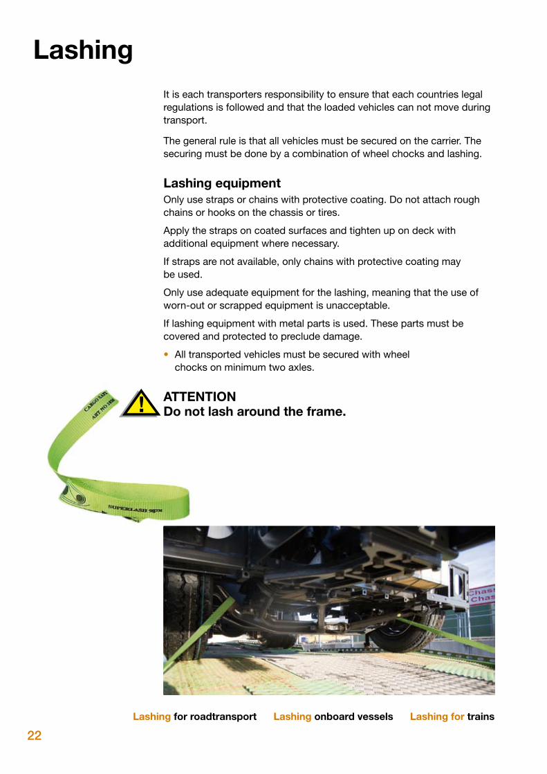
If lashing equipment with metal parts is used. These parts must be covered and protected to preclude damage.
• All transported vehicles must be secured with wheel chocks on minimum two axles.
ATTENTION Do not lash around the frame.
Lashing for roadtransport Lashing onboard vessels Lashing for trains
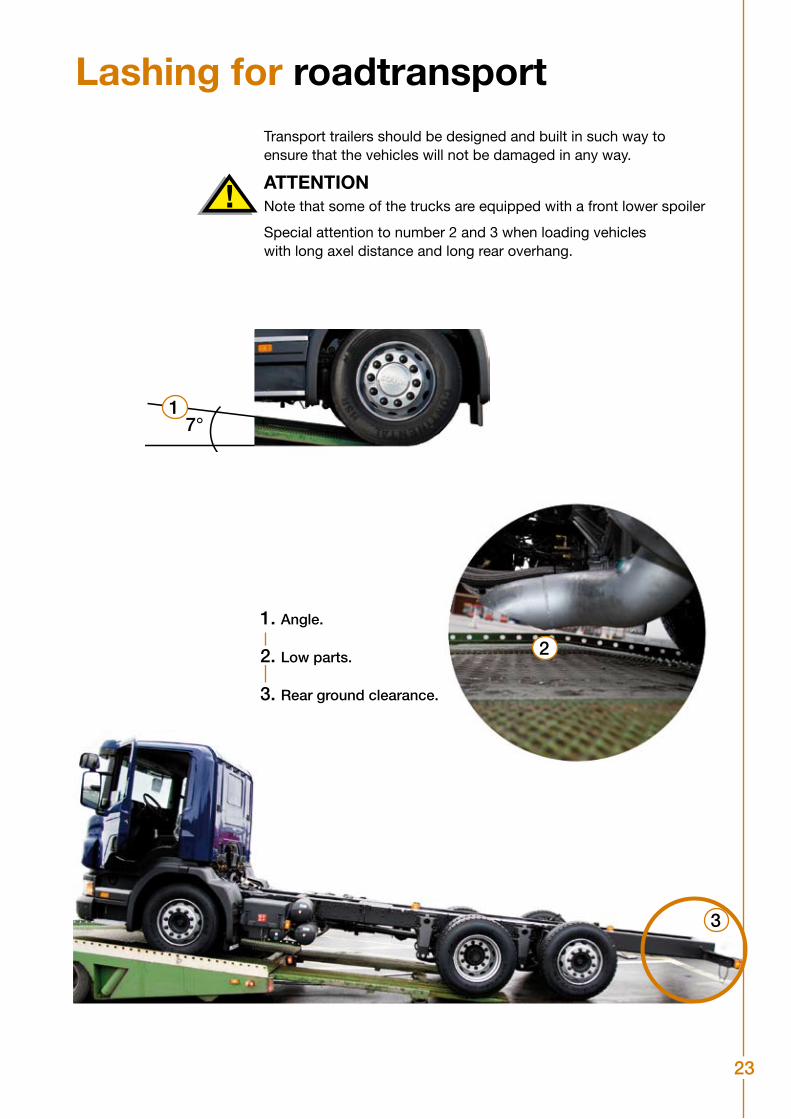
23
Lashing for roadtransportTransport trailers should be designed and built in such way to ensure that the vehicles will not be damaged in any way.
ATTENTIONNote that some of the trucks are equipped with a front lower spoiler
Special attention to number 2 and 3 when loading vehicles with long axel distance and long rear overhang.
7°
1. Angle.
2. Low parts.
3. Rear ground clearance.
2
1
3
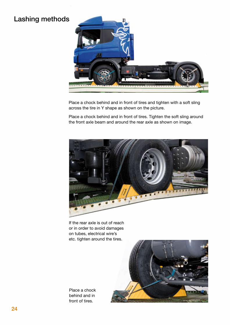
24
Place a chock behind and in front of tires and tighten with a soft sling across the tire in Y shape as shown on the picture.
Place a chock behind and in front of tires. Tighten the soft sling around the front axle beam and around the rear axle as shown on image.
Place a chock behind and in front of tires.
If the rear axle is out of reach or in order to avoid damages on tubes, electrical wire’s etc. tighten around the tires.
Lashing methods
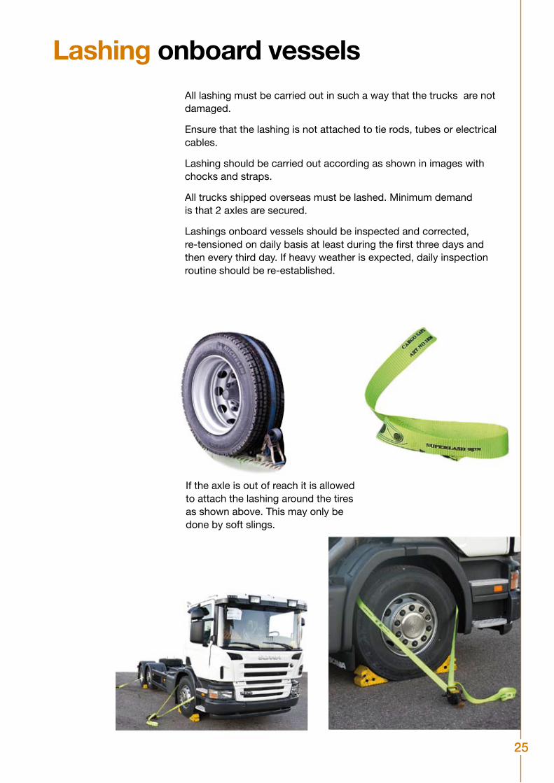
25
Lashing onboard vesselsAll lashing must be carried out in such a way that the trucks are not damaged.
Ensure that the lashing is not attached to tie rods, tubes or electrical cables.
Lashing should be carried out according as shown in images with chocks and straps.
All trucks shipped overseas must be lashed. Minimum demand is that 2 axles are secured.
Lashings onboard vessels should be inspected and corrected, re-tensioned on daily basis at least during the first three days and then every third day. If heavy weather is expected, daily inspection routine should be re-established.
If the axle is out of reach it is allowed to attach the lashing around the tires as shown above. This may only be done by soft slings.
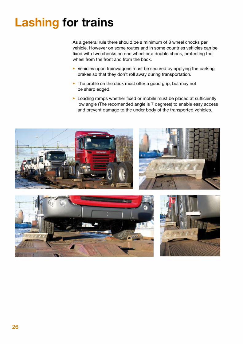
26
Lashing for trainsAs a general rule there should be a minimum of 8 wheel chocks per vehicle. However on some routes and in some countries vehicles can be fixed with two chocks on one wheel or a double chock, protecting the wheel from the front and from the back.
• Vehicles upon trainwagons must be secured by applying the parking brakes so that they don’t roll away during transportation.
• The profile on the deck must offer a good grip, but may not be sharp edged.
• Loading ramps whether fixed or mobile must be placed at sufficiently low angle (The recomended angle is 7 degrees) to enable easy access and prevent damage to the under body of the transported vehicles.
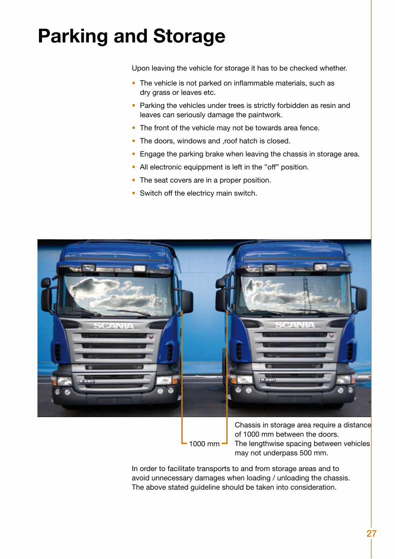
27
Parking and StorageUpon leaving the vehicle for storage it has to be checked whether.
• The vehicle is not parked on inflammable materials, such as dry grass or leaves etc.
• Parking the vehicles under trees is strictly forbidden as resin and leaves can seriously damage the paintwork.
• The front of the vehicle may not be towards area fence.
• The doors, windows and ,roof hatch is closed.
• Engage the parking brake when leaving the chassis in storage area.
• All electronic equippment is left in the ”off” position.
• The seat covers are in a proper position.
• Switch off the electricy main switch.
1000 mm
Chassis in storage area require a distance of 1000 mm between the doors. The lengthwise spacing between vehicles may not underpass 500 mm.
In order to facilitate transports to and from storage areas and toavoid unnecessary damages when loading / unloading the chassis.The above stated guideline should be taken into consideration.
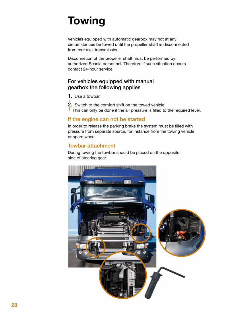
28
TowingVehicles equipped with automatic gearbox may not at any circumstances be towed until the propeller shaft is disconnected from rear axel transmission.
Disconnetion of the propeller shaft must be performed byauthorized Scania personnel. Therefore if such situation occurscontact 24-hour service.
For vehicles equipped with manual gearbox the following applies
1. Use a towbar.
2. Switch to the comfort shift on the towed vehicle. This can only be done if the air pressure is filled to the required level.
If the engine can not be startedIn order to release the parking brake the system must be filled with pressure from separate source, for instance from the towing vehicle or spare wheel.
Towbar attachmentDuring towing the towbar should be placed on the opposite side of steering gear.

29
© Copyright Scania 2008 All rights reserved. Scania AB (publ) SE-151 87 Södertälje Sweden
Tel: +46-8-55 38 10 00 Fax: +46-8-55 38 10 37
AR 0800 999 722 624 IE +353 719 634 000
AT +43 12 564 411 IT +39 0461 996 222
AU 1300 SCANIA KR +82 15 886 575
1300 722 624
BE +32 2 264 00 00 LU +32 27 228 413
BG +35 9886 660 001 MA +34 916 789 213
BR 0800 194 224 MX +52 01 800 4SCANIA
CH +41 800 552 400 NL +31 704 182 666
CL 188 800 722 642 NO +47 22 321 700
48 602 622 465
CZ +42 0225 020 255 PL +48 602 622 456
DE +49 261 887 8888 PT +48 602 622 465
DK +45 333 270 44 RO +40 723 272 726
ES +34 91 678 80 58 SE +46 42 100 100
FI +35 810 555 24 SK +42 1903 722 048
FR +33 241 413 232 TR +90 2123 350 440
UK 0800 800 660 TZ +25 5744 722 642
Abroad: +44 1274 301 260
GR +30 6944 420 410 ZA 0800 005 798
HU +36 209 727 197
For other countries: +46 8 52 24 24 24 Please note that for staff training reasons phone calls may be recorded.
24 hours assistanceThe assistance service is available in most European countries as well as in Brazil and Argentina. If you wish to know if a particular workshop can provide 24 hour service, please look for this symbol. Visit your local distributor for more information.
Scania customer national phone numbers to reach Scania Assistance.

30
DamageIf the vehicle is damaged, it is the obligation of the carrier / transport company to guarantee proper measures in order to avoid further damages. i.e. cover broken windscreens, secure loose parts etc.
A thorough inspection of all the vehicles must be performed at each handling point prior to the loading / driving and any damages (scratches, dents, theft etc) or loss should be noted on the waybill/bill of lading.
Major damages such as transport accidents total loss or other severe damage, theft, fire vandalism, traffic accidents etc or damages which affect the road safety of the vehicle etc must be reported immediately to Scania’s delivery function for a decision whether if the vehicle should continue the transport to final destination or somewhere else.
31
AuditAs a part of Scania’s pursuit of improvements, Scania CV AB or itsrepresentatives will perform random surveys and continuous auditsof all areas such as terminals, ports, carriers and vessels. We reserveour right to inform the responsible part if Scania’s requirements orroutines are not followed correctly.
It is the obligation of each company and contractor appointed by Scania CV AB for ensuring that all involved personnel is notified and aware of these handling instructions. This responsibility includes the compliance of any temporary involved or subcontracted personnel who may be a part in the movement of Scania vehicles world wide.

32
Notes

33
Notes

34
Notes

35
Notes

36
© Copyright Scania 2008 All rights reserved. Scania CV AB (publ),
SE-151 87 Södertälje, Sweden.
Outbound Logistics ph: +46 8 553 81000