Embed Size (px)
Citation preview

INTRODUCTION 2PRE-INSTALLATION 3PREVENTIVE MAINTENANCE 3 Vehicle Preparation 3 Every 25,000 Miles 4FAN CLUTCH REMOVAL 5REPAIR KIT INSTALLATION 5INSTALLATION 8TROUBLESHOOTING 9PARTS LIST 11
HORTON DIESLTEMP®
FAN CLUTCHHT650TM
SERVICING INSTRUCTIONS
○ ○ ○ ○ ○ ○ ○ ○ ○ ○ ○ ○ ○ ○ ○ ○ ○ ○
○ ○ ○ ○ ○ ○ ○ ○ ○ ○ ○ ○ ○ ○ ○ ○ ○ ○
○ ○ ○ ○ ○ ○ ○ ○ ○ ○ ○ ○ ○ ○ ○ ○
○ ○ ○ ○ ○ ○ ○ ○ ○ ○ ○ ○ ○ ○
○ ○ ○ ○ ○ ○ ○ ○ ○ ○ ○ ○ ○ ○ ○ ○ ○ ○ ○ ○ ○ ○ ○
○ ○ ○ ○ ○ ○ ○ ○ ○ ○ ○ ○ ○ ○ ○ ○ ○ ○
○ ○ ○ ○ ○ ○ ○ ○ ○ ○ ○ ○ ○ ○ ○ ○ ○ ○ ○ ○ ○ ○
○ ○ ○ ○ ○ ○ ○ ○ ○ ○ ○ ○ ○ ○ ○ ○ ○ ○ ○
○ ○ ○ ○ ○ ○ ○ ○ ○ ○ ○ ○
○ ○ ○ ○ ○ ○ ○ ○ ○ ○ ○ ○ ○ ○ ○ ○ ○ ○ ○ ○ ○ ○ ○ ○ ○ ○
INTRODUCTION
Read this manual carefully, making useof its explanations. This manualdescribes the correct Inspection, Service,and Repair procedures for HortonHT650TM Fan Clutches. Following theinstructions carefully will provide thesafest and most trouble-free operation.
Horton uses the following specialnotices to give warning of possiblesafety-related problems which couldcause serious injury, and providesinformation to help prevent damage toequipment.
Danger is used to indicate thepresence of a hazard which will causesevere personal injury, death, orsubstantial property damage if thewarning is ignored.
Denotes that a potential hazardexists and indicates procedures thatmust be followed exactly to eithereliminate or reduce the hazard, andto avoid serious personal injury, orprevent future safety problems withthe vehicle.
Caution is used to indicate thepresence of a hazard which will orcan cause minor personal injury orproperty damage if the warning isignored.
NOTEAdvises of operation, procedure, orinstruction that is inserted forcorrect service providing greaterowner satisfaction. A note can alsoprovide information that will makeservice quicker and easier.
2

You must follow your company safetypractices, which should adhere to or bebetter than Federal or State approvedshop safety practices and procedures.Be sure that you understand all theprocedures and instructions before youbegin work on this unit.
NOTEParts replacement and/or repair ofyour Horton DIESLTEMP® Fan Clutchshould be performed only by theHorton Factory or an authorizedHorton Distributor or Dealer to keepyour warranty coverage intactduring the warranty period.
PRE-INSTALLATION
3
PREVENTIVE MAINTENANCE
Vehicle Preparation
Before performing tests on the FanClutch, be sure to follow good shopsafety practices and:
• Apply the vehicle’s parking brake.
• Block the vehicle’s wheels.
Before doing work in the area of the fan:
• Start the vehicle’s engine and buildair pressure in excess of 90 PSI.
• Observe the fan and Fan Clutch froma distance, look for vibration, fanblade contact, Fan Clutch slippage,and Fan Clutch operation.
• Turn engine off.
Be sure engine is turned off and fanhas stopped turning beforeapproaching fan area, to preventserious personal injury.

Every 25,000 Miles
Fan and Fan Belt
1. Check the fan for looseness anddamage, such as bent, cracked ormissing blades, loose rivets ormissing weights. Retorque if loose.Replace if damaged.
2. Check for adequate clearancebetween the fan and the fanshroud or other enginecompartment components. Repairif the clearance is inadequate.
3. Check the fan belt condition, belttension, and belt alignment.Correct if necessary.
Friction Facing
1. Check for wear condition. Replacewhen worn to 1/16’’ thick, oilspotted, or if burn marks are visible.
4
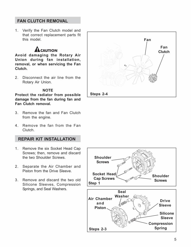
FAN CLUTCH REMOVAL
1. Verify the Fan Clutch model andthat correct replacement parts fitthis model.
Avoid damaging the Rotary AirUnion during fan installation,removal, or when servicing the FanClutch.
2. Disconnect the air line from theRotary Air Union.
NOTEProtect the radiator from possibledamage from the fan during fan andFan Clutch removal.
3. Remove the fan and Fan Clutchfrom the engine.
4. Remove the fan from the FanClutch.
Steps 2-4
5
REPAIR KIT INSTALLATION
1. Remove the six Socket Head CapScrews; then, remove and discardthe two Shoulder Screws.
2. Separate the Air Chamber andPiston from the Drive Sleeve.
3. Remove and discard the two oldSilicone Sleeves, CompressionSprings, and Seal Washers.
Steps 2-3
Step 1
Fan
FanClutch
Socket HeadCap Screws Shoulder
Screws
ShoulderScrews
Air Chamberand
Piston
DriveSleeve
SiliconeSleeve
CompressionSpring
SealWasher

Steps 4-8
Steps 9-12
6
4. Separate the Air Chamber from theold Piston and discard the old Pistonand O-ring Seal.
5. Examine the inside of the AirChamber for signs of dirt andforeign material. The Air Chambershould be relatively clean and dry.If not, a problem may exist in thevehicle air system and must becorrected before the Fan Clutch isreinstalled.
6. Using parts cleaning solvent, cleanthe o-ring contact surfaces of theAir Chamber and new Piston.
7. Lubricate the new O-ring Seal andO-ring seal contact surfaces of theAir Chamber with the o-ringlubricant supplied in the Repair Kit;then, install the new O-ring Sealinto the Air Chamber.
8. Press the new Piston into the AirChamber.
NOTEIf you are installing a new DriveSleeve, continue with Step 9. If youare not installing a new Drive Sleevego to Step 15.
9. Remove the Hex. Head Cap Screwand Washer; then, slide theMounting Bracket and Hex. Bracketoff the splined hub of the FrictionDisc.
10. Slide the Friction Disc out of theDrive Sleeve.
11. Slide the Friction Disc into the newDrive Sleeve.
12. Slide the Mounting Bracket andHex. Bracket onto the splined hubof the Friction Disc.
AirChamber
O-ringSeal
Piston
Hex. HeadCap Screw
Washer
Mounting Bracketand
Hex. Bracket
DriveSleeve
FrictionDisc

13. Install the two new Silicone Sleevesover the new Compression Springsand onto the Drive Sleeve.
14. Place the two new Seal Washers ontop of the new CompressionSprings.
15. Align the Air Chamber and newPiston with the tabs of the DriveSleeve.
16. Apply a drop of Loctite® 242 to thethreads of the two new ShoulderScrews and secure the Air Chamberand new Piston to the Drive Sleeve.
17. Alternately and evenly torque thetwo new Shoulder Screws to20-25 Ft. Lbs. [27.1-33.9 N•m].
18. Apply a drop of Loctite® 242 halfway down the threads of the sixSocket Head Cap Screws and installthe six Socket Head Cap Screws.
19. Alternately and evenly torque thesix Socket Head Cap screws to 20-25 Ft. Lbs. [27.1-33.9 N•m]. Steps 15-19
Steps 13-14
Steps 20-24
NOTEIf you are replacing the Rotary AirUnion, continue with Step 22.
20. Remove the three Pan Head Screwsand the old Retaining Washer;then, remove the old Rotary AirUnion and old O-ring Seal.
21. Lubricate the new O-ring Seal withthe o-ring lubricant supplied in theRepair Kit; then, install the newO-ring Seal into the Air Chamber.
22. Press the new Rotary Air Union intothe Air Chamber and new O-ringSeal.
Air Chamberand
Piston
DriveSleeve
SiliconeSleeve
SealWasher
CompressionSpring
Socket HeadCap Screws Shoulder
Screws
ShoulderScrews
Pan HeadScrew
Rotary AirUnion
O-ringSeal
RetainingWasher
AirChamber
7

23. Slide the new Retaining Washerover the new Rotary Air Union.
24. Install and torque the three PanHead Screws to 13-17 In. Lbs.[1.5-1.9 N•m].
Steps 1-2
FanClutch
Fan
Suppliednuts and lockwashers
8
INSTALLATION
Avoid damaging the Rotary AirUnion during fan installation,removal, or when servicing the FanClutch.
1. Using supplied nuts andlockwashers, mount the fan ontothe Fan Clutch; then, torque thenuts to 10 Ft. Lbs. [13.6 N•m].
2. Using SAE grade 8 bolts, install thefan and Fan Clutch assembly ontothe fan drive pulley. Torque themounting bolts to 25 Ft. Lbs.[33.9 N•m].
3. Make the air line connectionsbetween the Solenoid Valve andthe Fan Clutch.
4. Check for proper air pressure to theFan Clutch. This measurementshould always be taken at the FanClutch air inlet port.
NOTETo assure maximum horsepowercarrying capacity of the Fan Clutchand to prevent damage to the FanClutch, there must be a minimumpressure of 90 to 120 PSI to the FanClutch upon engagement.
5. Affix the WARNING sticker to ahighly visible area of the enginecompartment.
4
Step 5

9
TROUBLESHOOTING
PROBLEM PROBABLE CAUSE SOLUTION
Fan Clutch fails to engage Electrical Problem
1. Broken circuit (NormallyOpen System).
2. Improperly wired.
1. Check electricalconnections.
2. Check wiring according todiagram.
3. Check Thermal Switch(N.O. or N.C.).
4. Replace the SolenoidValve.
Air Problem
1. Air leaks in Fan Clutch. 1. Install new O-ring Seals.2. Check the Rotary Air Union
and air lines for leaks orrestrictions.
3. Replace the SolenoidValve.
Fan Clutch fails to disengage
Electrical Problem
1. Broken circuit (NormallyClosed System).
1. Check electricalconnections.
2. Check wiring according todiagram.
3. Replace Thermal Switch.
Air Problem
1. Air line restricted, notallowing air to exhaustfrom Fan Clutch.
1. Check the air line betweenthe Fan Clutch andSolenoid Valve forrestrictions or obstructions.
2. Replace the SolenoidValve.
3. Thermal Switch incorrectfor application.
4. Bad Solenoid Valve.
2. Restricted air supply to theFan Clutch.
3. Bad Solenoid Valve.
2. Improperly wired.
3. Bad Thermal Switch.
2. Bad Solenoid Valve.
Fan Clutch engaged, engine running hot
1. Check for shutter oper-ation, winter fronts, orobstructions in front ofradiator.
2. Refer to vehicle enginemanual.
1. Restriction in front ofradiator.
2. Cooling system mal-function.
Troubleshooting continued onPage 10.

PROBLEM PROBABLE CAUSE SOLUTION
Fan Clutch cycles frequently
Electrical Problem
1. Poor ground wire connection.2. Improper temperature
control settings.
1. Check electricalconnections.
2. Check temperature settingof all controls. ThermalSwitch setting shouldengage the Fan Clutch100 F higher than the fullopen temperature of thethermostat.
3. Check the A/C PressureSwitch. Use higher switch.
4. Check for shutteroperation, winter fronts, orobstructions in front of theradiator.
5. Replace the ThermalSwitch.
6. Replace the Air-TempSwitch.
3. A/C Pressure Switch settingtoo low.
4. Restriction in front of radiator, blocking air flow.
5. Faulty Thermal Switch.
6. Faulty Air-Temp Switch.
Air Problem
1. Air line restricted, notallowing air to be releasedfrom the Fan Clutch.
1. Check for pinching orplugging of the air linebetween the Fan Clutchand the Solenoid Valve.
2. Check for a pluggedexhaust port on theSolenoid Valve. Clean orreplace the Solenoid valve.
2. Solenoid Valve not exhausting.
10

11
ITEM DESCRIPTION QTY
11 Air Chamber 112 Socket Head Cap Screw 613 Set Screw 2
141 Seal Washer 215 Retaining Washer 116 Pan Head Screw 3
221 Shoulder Screw (Locking) 226 Hex. Bracket 127 Rotary Air Union Assembly 128 O-ring Seal 1
291 Warning Sticker 1
PARTS LIST
ITEM DESCRIPTION QTY
1 Hex. Head Cap Screw 12 Mounting Bracket 13 Drive Sleeve 1
(Includes Bearing)4 Friction Disc 1
51 Silicone Sleeve 26 Washer 1
81 Piston 1(Includes Friction Facing
and Sleeve Bearings) 91 Compression Springs 2 101 O-ring Seal 1
HT650Exploded View
1
2
2 6
6
3
5
5
9
94
1 4
1 4
8
1 1
1 0
1 3
1 3
2 2
2 2
2 8
2 7
1 2
1 6
1 5
1 Denotes Repair Kit item. Repair Kit Part No. 994317.
2 9

R
Horton, Inc.2565 Walnut St.Roseville, MN 551131-800-621-1320www.hortoninc.com
FACTORY: Britton, SD 57430-0050
© Copyright Horton Vehicle Components, Inc., A subsidiary of Horton, Inc., 1997.All rights reserved. Printed in U.S.A.
L-22610-A-0197