Embed Size (px)
DESCRIPTION
behnam behroozpour EE40, summer 2015 HW 6
Citation preview
HW 6
Behroozpour
Summer 2015 Posted: Wed 7/22/2015 Due: Fri 7/31/2015 -‐ 11pm
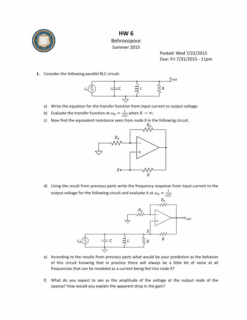
1. Consider the following parallel RLC circuit:
a) Write the equation for the transfer function from input current to output voltage. b) Evaluate the transfer function at 𝜔! =
!!" when 𝑅 → ∞.
c) Now find the equivalent resistance seen from node X in the following circuit.
d) Using the result from previous parts write the frequency response from input current to the
output voltage for the following circuit and evaluate it at 𝜔! =!!".
e) According to the results from previous parts what would be your prediction as the behavior
of this circuit knowing that in practice there will always be a little bit of noise at all frequencies that can be modeled as a current being fed into node X?
f) What do you expect to see as the amplitude of the voltage at the output node of the opamp? How would you explain the apparent drop in the gain?
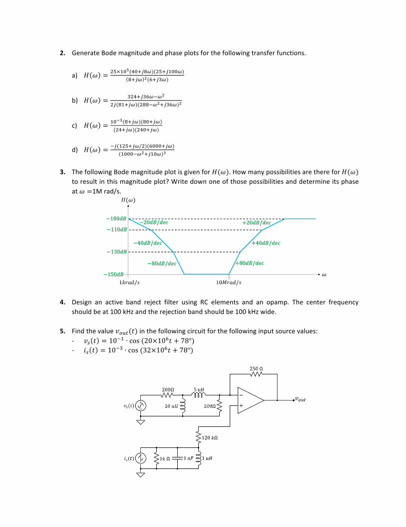
2. Generate Bode magnitude and phase plots for the following transfer functions.
a) 𝐻 𝜔 = !"×!"!(!"!!!!)(!"!!!""!)!!!" !(!!!!!)
b) 𝐻 𝜔 = !"#!!!"!!!!
!!(!"!!")(!""!!!!!!"!)!
c) 𝐻 𝜔 = !"!!(!!!")(!"!!")(!"!!")(!"#!!")
d) 𝐻 𝜔 = !!(!"#!!"/!)(!"""!!")(!"""!!!!!!"!)!
3. The following Bode magnitude plot is given for 𝐻(𝜔). How many possibilities are there for 𝐻(𝜔)
to result in this magnitude plot? Write down one of those possibilities and determine its phase at 𝜔 =1M rad/s.
4. Design an active band reject filter using RC elements and an opamp. The center frequency should be at 100 kHz and the rejection band should be 100 kHz wide.
5. Find the value 𝑣!"#(𝑡) in the following circuit for the following input source values: -‐ 𝑣! 𝑡 = 10!! ∙ cos (20×10!𝑡 + 78°) -‐ 𝑖! 𝑡 = 10!! ∙ cos (32×10!𝑡 + 78°)