Embed Size (px)
Citation preview

8/12/2019 Informacion Bombas Goulds
http://slidepdf.com/reader/full/informacion-bombas-goulds 1/20
Section B -- Pump Application DataB-1 Corrosion & Materials of Construction Selecting the right pump type and sizing it correctly are critical to the success of any pumpapplication. Equally important is the selection of materials of construction. Choices must bemade between metals and/or non-metals for pump components that come into contact withthe pumpage. In addition, gasets and !-ring material selections must be made to assure
long lea-free operation of the pump"s dynamic and static sealing #oints. $o assist in properselection, included in this section is a brief discussion of specific types of corrosion and ageneral material selection guide.
Corrosion Corrosion is the destructi%e attac of a metal by chemical or electra-chemical reaction with itsen%ironment. It is important to understand the %arious types of corrosion and factors affectingcorrosion rate to properly select materials.
TYPES OF CORROSION
&. 'al%anic corrosion is the electro-chemical action produced when one metal is inelectrical contact with another more noble metal, with both being immersed in the samecorroding medium called the electrolyte. ( gal%anic cell is formed and current flowsbetween the two materials. $he least noble material called the anode will corrode while
the more noble cathode will be protected. It is important that the smaller wearing partsin a pump be of a more noble material than the larger more massi%e parts, as in an ironpump with bronze or stainless steel trim. )ollowing is a gal%anic series listing the morecommon metals and alloys.
Corroded End*(nodic, or least noble+agnesiumagnesium (lloysinc (luminum SCadmium (luminum &0$Steel or IronCast IronStainless Steel, 122 Series*(cti%e+Stainless Steel, $ype 321*(cti%e+Stainless Steel, $ype 3&4*(cti%e+5ead-tin Solders5ead$in6icel *(cti%e+
6icel base alloy *acti%e+7rassesCopper 7ronzesCopper-6icel (lloyonelSil%er Solder 6icel *8assi%e+6icel 7ase (lloy *8assi%e+Stainless Steel, 122 Series*8assi%e+Stainless Steel, $ype 321*8assi%e+
Stainless Steel, $ype 3&4*8assi%e+Sil%er

8/12/2019 Informacion Bombas Goulds
http://slidepdf.com/reader/full/informacion-bombas-goulds 2/20
'raphite'oldPlatinum Protected End*Cathodic, or most noble+
• . 9niform Corrosion is the o%erall attac on a metal by a corrod-ing liquid resulting in a
relati%ely uniform metal loss o%er the e:posed surface. $his is the most common type of
corrosion and it can be minimized by the selection of a material which offers resistanceto the corroding liquid.
• 3. Intergranular corrosion is the precipitation of chromium carbides at the grain
boundaries of stainless steels. It results in the complete destruction of the mechanicalproperties of the steel for the depth of the attac. Solution annealing or the use of e:tralow carbon stainless steels will eliminate intergranular corrosion.
• 1. 8itting Corrosion is a localized rather than uniform type of attac. It is caused by a
breadown of the protecti%e film and results in rapid pit formation at random locationson the surface.
• 0. Cre%ice or Concentration Cell Corrosion occurs in #oints or small surface
imperfections. 8ortions of the liquid become trapped and a difference in potential isestablished due to the o:ygen con-centration difference in these cells. $he resultingcorrosion may progress rapidly lea%ing the surrounding area unaffected.
• 4. Stress Corrosion is the failure of a material due to a combina-tion of stress and
corrosi%e en%ironment, whereas the material would not be affected by the en%ironmentalone.
• . Erosion-Corrosion is the corrosion resulting when a metal;s protecti%e film is
destroyed by high %elocity fluids. It is distinguished from abrasion which is destructionby fluids containing abrasi%e solid particles.
pH VALUES $he p< of a liquid is an indication of its corrosi%e qualities, either acidic or alaline. It is ameasure of the hydrogen or hydro:ide ion concentration in gram equi%alents per liter. p<%alue is e:pressed as the logarithm to the base &2 of the reciprocal of the hydrogen ionconcentration. $he scale of p< %alues is from zero to &1, with as a neutral point. )rom 4 to
zero denotes increasing hydrogen ion con-centration and thus increasing acidity, and from =to &1 denotes increasing hydro:ide ion concentration and thus increasing alalinity.
$he table below outlines materials of construction usually recommended for pumps handlingliquids of nown p< %alue
pH Value Material of Construction
&2 to &1 Corrosion >esistant (lloys
= to &24 to =1 to 4
Iron, Stainless Steel, 7ronze, Carbon Steel
2 to 1 Corrosion >esistant (lloys
$he p< %alue should only be used as a guide with wea aqueous solutions. )or morecorrosi%e solutions, temperature and chemical composition should be carefully e%aluated inthe selection of materials of construction.
B-2 Material Selection Chart
$his chart is intended as a guide in the selection of economical materials. It must be ept inmind that corrosion rates may %ary widely with tem-perature, concentration, and the presenceof trace elements or abrasi%e solids. 7lan spaces in the chart indicate a lac of accuratecorrosion data for those specific conditions. In general, the chart is limited to metals and non-metals regularly furnished by I$$-'oulds.
Note: a:imum temperature limits are shown where data is a%ailable. Contact a 'ouldsrepresentati%e for temperature limits of all materials before final material selection.
Code:
A Recommended
8/12/2019 Informacion Bombas Goulds
http://slidepdf.com/reader/full/informacion-bombas-goulds 3/20
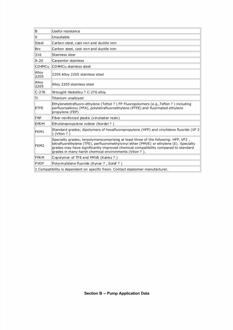
B Useful resistance
X Unsuitable
Steel Carbon steel, cast iron and ductile iron
Brz Carbon steel, cast iron and ductile iron
316 Stainless steel
A-20 Carenter stainless
C!"#Cu C!"#Cu stainless steel
Allo$220%
220% Allo$ 220% stainless steel
Allo$220%
Allo$ 220% stainless steel
C-2&6 'rou()t *astello$ + C-2&6 allo$
i itanium unallo$ed
.
t)$lenetetrafluoro-et)$lene /efzel + . .luorool$mers /e(,eflon + includin(
erfluoroalo4$ /.A, ol$tetrafluoroet)$lene /. and fluorinated et)$lenero$lene /.
.R .iber-reinforced lastic /5in$lester resin
!# t)$lenero$lene rubber /ordel +
.7#1Standard (rades8 diol$mers of )e4afluororo$lene /*. and 5in$lidene fluoride /9. 2 /9iton +
.7#2
Secialt$ (rades8 terol$merscomrisin( at least t)ree of t)e follo:in(; *., 9.2 ,tetrafluoret)$lene /., erfluoromet)$l5in$l et)er /#9 or et)$lene / Secialt$
(rades ma$ )a5e si(nificantl$ imro5ed c)emical comatibilit$ comared to standard(rades in man$ )ars) c)emical en5ironments /9iton +
..7# Cool$mer of . and #9 /7alrez +
9!. ol$5in$lidene fluoride /7$nar + , Solef +
1 Comatibilit$ is deendent on secific freon Contact elastomer manufacturer
Section B -- Pump Application Data

8/12/2019 Informacion Bombas Goulds
http://slidepdf.com/reader/full/informacion-bombas-goulds 4/20
B-4A Sealing $he proper selection of a seal is critical to the success of e%ery pump application. )orma:imum pump reliability, choices must be made between the type of seal and the sealen%ironment. In addition, a sealless pump is an alternati%e, which would eliminate the needfor a dynamic type seal entirely.
Sealin Basics
$here are two basic inds of seals? static and dynamic. Static seals are employed where nomo%ement occurs at the @uncture to be sealed. 'asets and !-rings are typical static seals.
Aynamic seals are used where surfaces mo%e relati%e to one another. Aynamic seals areused, for e:ample, where a rotating shaft transmits power through the wall of a tan *)ig. &+,through the casing of a pump *)ig. +, or through the housing of other rotating equipmentsuch as a filter or screen.
Fig. 1 Cross Section of Tan an! Mi"er
Fig. 2 T#$ical Centrif%gal P%&$ ( common application of sealing de%ices is to seal the rotating shaft of a centrifugal pump. $obest understand how such a seal functions a quic re%iew of pump fundamentals is in order.
In a centrifugal pump, the liquid enters the suction of the pump at the center *eye+ of therotating impeller *)igures 3 and 1+.

8/12/2019 Informacion Bombas Goulds
http://slidepdf.com/reader/full/informacion-bombas-goulds 5/20
Fig. ' Centrif%gal P%&$( )ig%i! En!
Fig. * Fl%i! Flo+ in Centrif%gal P%&$ (s the impeller %anes rotate, they transmit motion to the incoming product, which then lea%esthe impeller, collects in the pump casing, and lea%es the pump under pressure through thepump discharge.
Aischarge pressure will force some product down behind the impeller to the dri%e shaft,where it attempts to escape along the rotating dri%e shaft. 8ump manufacturers use %ariousdesign techniques to reduce the pressure of the product trying to escape. Such techniquesinclude? &+ the addition of balance holes through the impeller to permit most of the pressure toescape into the suction side of the impeller, or + the addition of bac pump-out %anes on thebac side of the impeller.
<owe%er, as there is no way to eliminate this pressure completely, sealing de%ices are
necessary to limit the escape of the product to the atmosphere. Such sealing de%ices aretypically either compression pacing or end-face mechanical seals.
B-4A Stuffing Box Packing ( typical paced stuffing bo: arrangement is shown in )ig. 0. It consists of? (+ )i%e rings ofpacing, 7+ ( lantern ring used for the in#ection of a lubricating and/or flushing liquid, and C+ (gland to hold the pacing and maintain the desired compression for a proper seal.

8/12/2019 Informacion Bombas Goulds
http://slidepdf.com/reader/full/informacion-bombas-goulds 6/20
Fig. , T#$ical St%ffing rrange&ent !escri$tion of $arts/$he function of pacing is to control leaage and not to eliminate it completely. $he pacing
must be lubricated, and a flow from 12 to 42 drops per minute out of the stuffing bo: must bemaintained for proper lubrication.
$he method of lubricating the pacing depends on the nature of the liquid being pumped aswell as on the pressure in the stuffing bo:. Bhen the pump stuffing bo: pressure is abo%eatmospheric pressure and the liquid is clean and nonabrasi%e, the pumped liquid itself willlubricate the pacing *)ig. 4+.
Fig. 0 T#$ical St%ffing rrange&ent +hen St%ffing Bo" Press%re is oe t&os$hericPress%re
Bhen the stuffing bo: pressure is below atmospheric pressure, a lantern ring is employed
and lubrication is in#ected into the stuffing bo: *)ig. +. ( bypass line from the pump dischargeto the lantern ring connection is normally used pro%iding the pumped liquid is dean.

8/12/2019 Informacion Bombas Goulds
http://slidepdf.com/reader/full/informacion-bombas-goulds 7/20
Fig. 3 T#$ical St%ffing Bo" rrange&ent +hen St%ffing Bo" Press%re is Belo+ t&os$hericPress%re
Bhen pumping slurries or abrasi%e liquids, it is necessary to in#ect a dean lubricating liquidfrom an e:ternal source into the lantern ring *)ig. =+. ( flow of from . to .0 gpm is desirableand a %al%e and flowmeter should be used for accurate control. $he seal water pressureshould be from &2 to &0 psi abo%e the stuffing bo: pressure, and anything abo%e this will onlyadd to pacing wear. $he lantern ring Is normally located In the center of the stuffing bo:.<owe%er, for e:tremely thic slurries lie paper stoc, it is recommended that the lantern ringbe located at the stuffing bo: throat to pre%ent stoc from contaminating the pacing.
Fig. 4 T#$ical St%ffing Bo" rrange&ent +hen P%&$ing Sl%rries$he gland shown in )igures 0 through = is a quench type gland. Bater, oil, or other fluids canbe in#ected into the gland to remo%e heat from the shaft, thus limiting heat transfer to thebearing frame. $his permits the operating temperature of the pump to be higher than the
limits of the bearing and lubricant design. $he same quench gland can be used to pre%ent theescape of a to:ic or %olatile liquid into the air around the pump. $his is called a smotheringgland, with an e:ternal liquid simply flushing away the undesirable leaage to a sewer orwaste recei%er.
$oday, howe%er, stringent emission standards limit use of pacing to non-hazardous waterbased liquids. $his, plus a desire to reduce maintenance costs, has increased preference formechanical seals.
Mechanical Seals ( mechanical seal is a sealing de%ice which forms a running seal between rotating andstationary parts. $hey were de%eloped to o%ercome the disad%antages of compressionpacing. 5eaage can be reduced to a le%el meeting en%ironmental standards of go%ernmentregulating agencies and maintenance costs can be lower. (d%antages of mechanical seals
o%er con%entional pacing are as follows?
&. ero or limited leaage of product *meet emission regulations.+

8/12/2019 Informacion Bombas Goulds
http://slidepdf.com/reader/full/informacion-bombas-goulds 8/20
. >educed friction and power loss.3. Elimination of shaft or slee%e wear.1. >educed maintenance costs.0. (bility to seal higher pressures and more corrosi%e en%ironments.4. $he wide %ariety of designs allows use of mechanical seals in almost all pump
applications.
!"e Basic Mec"anical Seal (ll mechanical seals are constructed of three basic sets of parts as shown in )ig. ?
&. ( set of primary seal faces? one rotary and one stationary;shown in )ig. as seal ringand insert.
. ( set of secondary seals nown as shaft pacings and insert mountings such as 2-rings, wedges and D-rings.
3. echanical seal hardware including gland rings, collars, compression rings, pins,springs and bellows.
Fig. 5 Si&$le Mechcanical Seal Ho# A Mec"anical Seal $or%s
$he primary seal is achie%ed by two %ery flat, lapped faces which create a difficult leaagepath perpendicular to the shaft. >ubbing contact between these two flat mating surfacesminimizes leaage. (s in all seals, one face is held stationar# in a housing and the other faceis fi:ed to, and rotates with, the shaft. !ne of the faces is usually a non-galling material suchas caron-gra$hite. $he other is usually a relati%ely hard material lie silicon-cari!e .Aissimilar materials are usually used for the stationary insert and the rotating seal ring face inorder to pre%ent adhesion of the two faces. $he softer face usually has the smaller matingsurface and is commonly called the +ear nose.
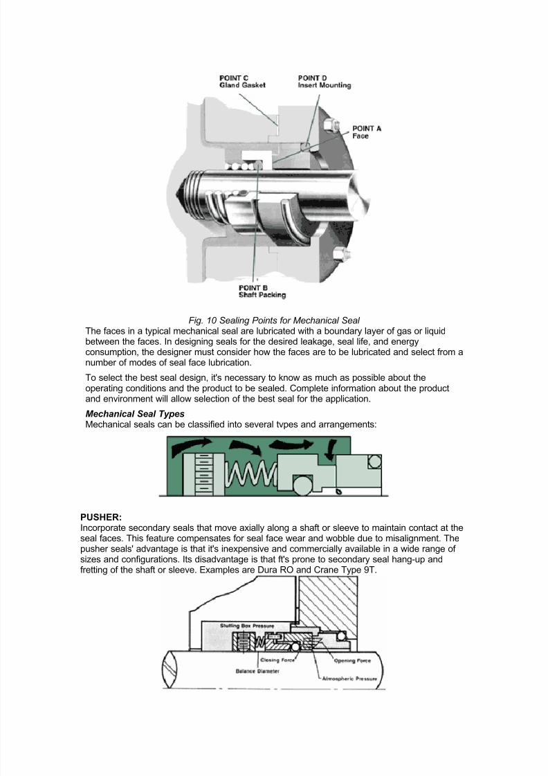
$here are four main sealing points within an end face mechanical seal *)ig. &2+. $he primary
seal is at the seal face, 8oint (. $he leaage path at 8oint 7 is bloced by either an 2-ring, aD-ring or a wedge. 5eaage paths at 8oints C and A are bloced by gasets or 2-rings.
8/12/2019 Informacion Bombas Goulds
http://slidepdf.com/reader/full/informacion-bombas-goulds 9/20
Fig. 16 Sealing Points for Mechanical Seal $he faces in a typical mechanical seal are lubricated with a boundary layer of gas or liquidbetween the faces. In designing seals for the desired leaage, seal life, and energyconsumption, the designer must consider how the faces are to be lubricated and select from anumber of modes of seal face lubrication.
$o select the best seal design, it"s necessary to now as much as possible about theoperating conditions and the product to be sealed. Complete information about the productand en%ironment will allow selection of the best seal for the application.
Mechanical Seal Types echanical seals can be classified into se%eral t%pes and arrangements?
PUSHE&: Incorporate secondary seals that mo%e a:ially along a shaft or slee%e to maintain contact at theseal faces. $his feature compensates for seal face wear and wobble due to misalignment. $hepusher seals" ad%antage is that it"s ine:pensi%e and commercially a%ailable in a wide range ofsizes and configurations. Its disad%antage is that ft"s prone to secondary seal hang-up andfretting of the shaft or slee%e. E:amples are Aura >! and Crane $ype $.

8/12/2019 Informacion Bombas Goulds
http://slidepdf.com/reader/full/informacion-bombas-goulds 10/20
UNBALANCED: $hey are ine:pensi%e, lea less, and are more stable when sub#ected to %ibration, misalignment,and ca%itation. $he disad%antage is their relati%e low pressure limit. If the closing force e:ertedon the seal faces e:ceeds the pressure limit, the lubricating film between the faces is squeezedout and the highly loaded dry running seal fails. E:amples are the Aura >! and Crane $.
C'NVEN!('NAL: E:amples are the Aura >! and Crane $ype & which require setting and alignment of the seal*single, double, tandem+ on the shaft or slee%e of the pump. (lthough setting a mechanical sealis relati%ely simple, today"s emphasis on reducing maintenance costs has increased preferencefor cartridge seals.
N'N-PUSHE&: $he non-pusher or bellows seal does not ha%e to mo%e along the shaft or slee%e to maintainseal face contact, $he main ad%antages are its ability to handle high and low temperatureapplications, and does not require a secondary seal *not prone to secondary seal hang-up+. (disad%antage of this style seal is that its thin bellows cross sections must be upgraded for use incorrosi%e en%ironments E:amples are Aura C7> and Crane &0, and Sealol 4=2.
BALANCED: 7alancing a mechanical seal in%ol%es a simple design change, which reduces the hydraulicforces acting to close the seal faces. 7alanced seals ha%e higher-pressure limits, lower sealface loading, and generate less heat. $his maes them well suited to handle liquids with poor
lubricity and high %apor pressures such as light hydrocarbons. E:amples are Aura C7> and87> and Crane =$ and &0.

8/12/2019 Informacion Bombas Goulds
http://slidepdf.com/reader/full/informacion-bombas-goulds 11/20
CA&!&(D)E: E:amples are Aura 8-S! and Crane &&22 which ha%e the mechanical seal premounted on aslee%e including the gland and fit directly o%er the odel 3&4 shaft or shaft slee%e *a%ailablesingle, double, tandem+. $he ma#or benefit, of course is no requirement for the usual seal settingmeasurements for their installation. Cartridge seals lower maintenance costs and reduce sealsetting errors.S(N)LE (NS(DE: $his is the most common type of mechanical seal. $hese seals are easily modified toaccommodate seal flush plans and can be balanced to withstand high seal en%ironmentpressures. >ecommended for relati%ely clear non-corrosi%e and corrosi%e liquids withsatisfactory" lubricating properties where cost of operation does not e:ceed that of a doubleseal. E:amples are Aura >! and C7> and Crane $ and &0. >eference Con%entional Seal.
S(N)LE 'U!S(DE: If an e:tremely corrosi%e liquid has good lubricating properties, an outside seal offers aneconomical alternati%e to the e:pensi%e metal required for an inside seal to resist corrosion.$he disad%antage is that it is e:posed outside of the pump which maes it %ulnerable todamage from impact and hydraulic pressure wors to open the seal faces so they ha%e lowpressure limits *balanced or unbalanced+.
D'UBLE *DUAL P&ESSU&(+ED,: $his arrangement is recommended for liquids that are not compatible with a single mechanicalseal *i.e. liquids that are to:ic, hazardous regulated by the E8(F, ha%e suspended abrasi%es, orcorrosi%es which require costly materials+. $he ad%antages of the double seal are that it canha%e fi%e times the life of a single seal in se%ere en%ironments. (lso, the metal inner seal parts
are ne%er e:posed to the liquid product being pumped, so %iscous, abrasi%e, or thermosettingliquids are easily sealed without a need for e:pensi%e metallurgy. In addition, recent testing has

8/12/2019 Informacion Bombas Goulds
http://slidepdf.com/reader/full/informacion-bombas-goulds 12/20
shown that double seal life is %irtually unaffected by process upset conditions during pumpoperation. ( significant ad%antage of using a double seal o%er a single seal.$he final decision between choosing a double or single seal comes down to the initial cost topurchase the seal, cost of operation of the seal, and en%ironmental and user plant emissionstandards for leaage from seals. E:amples are Aura double >! and G-22 and Cranedouble =&&$.
D'UBLE )AS BA&&(E& *P&ESSU&(+ED DUAL )AS,: Dery similar to cartridge double seals ... sealing in%ol%es an inert gas, lie nitrogen, to act as asurface lubricant and coolant in place of a liquid barrier system or e:ternal flush required withcon%entional or cartridge double seals. $his concept was de%eloped because many barrierfluids commonly used with double seals can no longer be used due to new emissionregulations. $he gas barrier seal uses nitrogen or air as a harmless and ine:pensi%e barrier fluidthat helps pre%ent product emissions to the atmosphere and fully complies with emissionregulations. $he double gas barrier seal should be considered for use on to:ic or hazardousliquids that are regulated or in situations where increased reliability is the required on anapplication. E:amples are Aura '7!!, ')!!, and Crane =22.
!ANDEM *DUAL UNP&ESSU&(+ED,: Aue to health, safety, and en%ironmental considerations,tandem seals ha%e been used for products such as %inyl chloride, carbon mono:ide, lighthydrocarbons, and a wide range of other %olatile, to:ic, carcinogenic, or hazardous liquids.$andem seals eliminate icing and freezing of light hydrocarbons and other liquids which couldfall below the atmospheric freezing point of water in air *3; ) or 2; C+. H$ypical buffer liquids inthese applications are ethylene glycol, methanol, and propanol.+ ( tandem also increases onlinereliability. If the primary seal fails, the outboard seal can tae o%er and function untilmaintenance of the equipment can be scheduled. E:amples are Aura $7-3 and tandem8$!.

8/12/2019 Informacion Bombas Goulds
http://slidepdf.com/reader/full/informacion-bombas-goulds 13/20
Section B -- Viration Anal.sis
Dibration analysis equipment enables you to tell when normal %ibration becomes problem%ibration or e:ceeds acceptable le%els. It may also allow you to determine the source and causeof the %ibration, thus becoming an effecti%e pre%enti%e maintenance and troubleshooting aid. ( %ibration analyser measures the amplitude, frequency and phase of %ibration. (lso when
%ibration occurs at se%eral frequencies, it separates one frequency from another so that eachindi%idual %ibra-tion characteristic can be measured.
$he %ibration picup senses the %elocity of the %ibration and con%erts it into an electricalsignal. $he analyzer recei%es this signal, con%erting it to the corresponding amplitude andfrequency.
$he amplitude is measured in terms of pea-to-pea displacement in mils *& mil J .22&+ andis indicated on the amplitude meter.
Some instruments are equipped with a frequency meter which gi%es a direct readout of thepredominant frequency of the %ibration. !ther instruments ha%e tunable filters which allowscanning the frequency scale and reading amplitude at any particular frequency, all othersbeing filtered out.
( strob light is used to determine the phase of %ibration. It can be made to flash at thefrequency of the %ibration present or at any arbitrary frequency set on an internal oscillator.
( reference mar on a rotating part %iewed under the strob light flashing at the %ibrationfrequency may appear as a single frozen *or rotat-ing+ mar, or as se%eral frozen *or rotating+mars. $he number of mars %iewed is useful in determining the source of the %ibration. $helocation of the mar or mars is used in balancing rotating parts.
$he first step in %ibration analysis is to determine the se%erity of the %ibration, then, if the%ibration is serious, a complete set of %ibration readings should be taen before attempting toanalyze the cause. )ig. & is the typical guide for end suction stoc pumps as published by the<ydraulic Institute. $he amplitudes shown are the o%erall >S obtained without filtering tospecific frequencies. (mplitudes at specific frequencies, such as %ane pass frequency withmulti-%ane impellers, should be less than 0K of the unfiltered amplitudes allowed in )ig. & at
the operating >8. )or other pumps, refer to <ydraulic Institute standards or pumpmanufacturer.

8/12/2019 Informacion Bombas Goulds
http://slidepdf.com/reader/full/informacion-bombas-goulds 14/20

8/12/2019 Informacion Bombas Goulds
http://slidepdf.com/reader/full/informacion-bombas-goulds 15/20
)ig. & (cceptable )ield Dibration 5imits for <orizontal 8umps - Clear 5iquid *>igid Structures+Se%erity of %ibration is a function of amplitude and pump speedL howe%er, it should be notedthat a change in se%erity o%er a period of time is usually a warning of impending failure. $hischange is often more important than %ibration in the slightly rough or rough ranges whichdoes not change with time.
Complete pump %ibration analysis requires taing %ibration readings at each bearing in three
planes *horizontal, %ertical and a:ial+. >eadings at the pump suction and discharge flangesmay also be useful in some cases.
(fter all data has been tabulated, it can be analyzed to determine the most liely cause orcauses of %ibration and the identifying characteristics of each.7y analyzing the tabulated %ibration data one or se%eral causes may be found. Each must becheced, starting with the most liely cause or easiest to chec.
)or e:ample, assume the a:ial %ibration is 02K or more of the radial %ibration and thepredominant frequency is the same as the >8 of the pump. $he chart indicates probablemisalignment or bent shaft. Coupling misalignment is probably the most common singlecause of pump %ibration and is one of the easiest to chec. If after checing, the alignmentpro%es to be good, then inspect for flange loading. )inally, chec for a bent shaft. Ca%itationin a pump can cause serious %ibration. Dibration at random frequencies can also be caused
by hydraulic disturbances in poorly designed suction or discharge systems.
$he use of %ibration equipment in pre%entati%e maintenance in%ol%es eeping a %ibrationhistory on indi%idual pieces of equipment in a plant. ( form similar to that shown in )ig 3 canbe used to record the %ibration data on a periodic routine basis. (brupt changes are a sign ofimpending failure. ( gradual increase in %ibration can also be detected and correcti%emeasures can be taen before it reaches a dangerous le%el.
)ig. 3 Dibration Identification Chart

8/12/2019 Informacion Bombas Goulds
http://slidepdf.com/reader/full/informacion-bombas-goulds 16/20
)ig. 1 Dibration Aata Sheet
Eniron!ental Controls En%ironmental controls are necessary for reliable performance of a mechanical seal on manyapplications. 'oulds 8umps and the seal %endors offer a %ariety of arrangements to combatthese problems.
&. Corrosion. $emperature Control3. Airty or incompatible en%ironments
C'&&'S('NCorrosion can be controlled by selecting seal materials that are not attaced by the pumpage.Bhen this is difficult, e:ternal fluid in#ection of a non-corrosi%e chemical to lubricate the seal ispossible. Single or double seals could be used, depending on if the customer can standdelusion of his product.!EMPE&A!U&E C'N!&'L (s the seal rotates, the faces are in contact. $his generates heat and if this heat is notremo%ed, the temperature in the stuffing bo: or seal chamber can increase and cause sealingproblems. ( simple by-pass of product o%er the seal faces will remo%e the heat generated bythe seal *)ig. 0+. )or higher temperature ser%ices, by-pass of product through a cooler may
be required to cool the seal sufficiently *)ig. 4+. E:ternal cooling fluid in#ection can also beused.

8/12/2019 Informacion Bombas Goulds
http://slidepdf.com/reader/full/informacion-bombas-goulds 17/20
D(&!/ or (NC'MPA!(BLE ENV(&'NMEN!Sechanical seals do not normally function well on liquids which contain solids or can solidifyon contact with the atmosphere. <ere, by-pass flush through a filter, a cyclone separator or astrainer are methods of pro%iding a clean fluid to lubricate seal faces. Strainers are effecti%efor particles larger than the openings on a 12 mesh screen. Cyclone separators are effecti%eon solids &2 micron or more in diameter, if they ha%e a specific gra%ity of . and the pump
de%elops a differential pressure of 32-12 psi. )ilters are a%ailable to remo%e solids micronsand larger.
If e:ternal flush with clean liquid is a%ailable, this is the most fail proof system. 5ip seal orrestricting bushings are a%ailable to control flow of in#ected fluid to flows as low as &/= '8.Muench type glands are used on fluids which tend to crystallize on e:posure to air. Bater orsteam is put through this gland to wash away any build up. !ther systems are a%ailable asrequired by the ser%ice.
AP" an# CP" Plans
(8I and C8I mechanical seal flush plans are commonly used with (8I and C8I processpumps. $he general arrangement of the plans are similar regardless of the designationwhether (8I or C8I. $he difference between the flush plans is the construction which pro%idesapplicable pressure-temperature capability for each type of pump. (8I plans ha%e higherpressure and temperature capability than C8I plans. Each plan helps pro%ide criticallubrication and cooling of seal faces to ma:imize seal reliability.
"-11 Pre#ictie an# Preentatie Maintenance Progra!
$his o%er%iew of 8redicti%e and 8re%entati%e aintenance *88+ is intended to assist thepump users who are starting a 88 program or ha%e an interest in the continuousimpro%ement of their current programs.
$here are four areas that should be incorporated in a 88 program. Indi%idually each one willpro%ide information that gi%es an indication of the condition of the pumpL collecti%ely they willpro%ide a complete picture as to the actual condition of the pump.
PUMP PE&0'&MANCE M'N(!'&(N)$here are si: parameters that should be monitored to understand how a pump is performing.$hey are Suction pressure *8s +, discharge pressure *8d+, flow *M+, pump speed *6 r +,

8/12/2019 Informacion Bombas Goulds
http://slidepdf.com/reader/full/informacion-bombas-goulds 18/20

8/12/2019 Informacion Bombas Goulds
http://slidepdf.com/reader/full/informacion-bombas-goulds 19/20
baseline %ibration measurement is taen that the operating point of the pump is also recorded.$he %ibration le%el of a pump is directly related to where it is operating and in relation to its 7estEfficiency 8oint *7E8+. $he further away from the 7E8, the higher the %ibrations will be. See thefollowing chart for a graphical representation of %ibration amplitude- %s- flow.
$he engineer must also loo at the frequency where the amplitude is occurring. )requencyidentifies what the defect is that is causing the problem, and the amplitude is an indication ofthe se%erity of the problem. $hese are general guidelines and do not co%er e%ery situation.$he spectrum in the chart is a typical spectrum for a pump that has an unbalance condition.
7earing defect analysis is another useful tool that can be used in many condition monitoringprograms. Each component of a roller bearing has its own unique defect frequency. Dibrationequipment a%ailable today enables the engineer to isolate the unique bearing defects anddetermine if the bearing is in distress. $his allows the user to shut the machine down prior toa catastrophic failure. $here are se%eral methods utilized but the most practical from a )ieldEngineering perspecti%e is called bearing en%eloping. In this method, special filters built intothe analyzer are used to amplify the repetiti%e high frequency signals in the high frequencyrange and amplify them in the low frequency part of the %ibration spectrum. 7earingmanufacturers publish the bearing defect frequency as a function of running speed whichallows the engineer to identify and monitor the defect frequency. Similar to con%entional%ibration analysis, a baseline must be established and then trended. $here are other methodsa%ailable such as <igh )requency Aetection *<)A+, and Spie Energy but the en%elopingtechnology is the latest de%elopment.
It is a common practice to monitor bearing temperature. $he most accurate method to monitorthe actual bearing temperature is to use a de%ice that will contact the outer race of thebearing. $his requires holes to be drilled into the bearing housings which is not alwayspractical. $he other method is the use of an infrared "gun" where the analyst aims the gun at apoint on the bearing housing where the temperature reading is going to be taen. !b%iously,this method is the most con%enient but there is a downside. $he temperature being measuredis the outside surface of the bearing housing, not the actual bearing temperature. $his mustbe considered when using this method.
$o complete the condition monitoring portion of a 88 program, many users ha%e begun anoil analysis program. $here are se%eral tests that can be performed on the lubricant todetermine the condition of the bearing or determine why a bearing failed so appropriatecorrecti%e action can be taen. $hese tests Include Spectrographic (nalysis, %iscosity
(nalysis, Infrared (nalysis, $otal (cid 6umber, Bear 8article (nalysis and Bear 8articleCount. ost of these tests ha%e to be performed under laboratory conditions. 8ortableinstruments are now a%ailable that enable the user to perform the test on site.

8/12/2019 Informacion Bombas Goulds
http://slidepdf.com/reader/full/informacion-bombas-goulds 20/20
PUMP S/S!EM ANAL/S(S8ump system analysis is often o%erlooed because it is assumed the system was constructedand operation of the pumps are in accordance with the design specifications. $his is often notthe case. ( proper system analysis begins with a system head cur%e. System head cur%es are%ery difficult to obtain from the end user and, more often than not, are not a%ailable. !n simplesystems, they can be generated in the field but on more complicated systems this can"t be
done. (s has been stated pre%iously, it is imperati%e to now where the pumps are beingoperated to perform a correct analysis and this is dependent on the system. ( typical system analysis will include the following informationL 68S<(, 68S<> , static head,friction loss through the system, and a complete re%iew of the piping configuration and%al%ing. $he process must also be understood because it ultimately dictates how the pumpsare being operated. (ll indicators may show the pump is in distress when the real problem isit is being run at low or high flows which will generate high hydraulic forces inside the pump.
C'NCLUS('N ( 88 program that incorporates all of the topics discussed will greatly enhance theeffecti%eness of the program. $he more complete understanding the engineer has of thepumping system, the more effecti%e the 88 program becomes.