Embed Size (px)
Citation preview

Introduction to Mechatronics
WOMEN IN AERONAUTICS
AND ASTRONAUTICS
(WIAA)
Sponsored by:
Women in Engineering
(WIE)
Workshop Leaders:
Elena Shrestha
Rose Weinstein

1
Table of Contents
The Arduino Uno Board……………………………………………………….…2
Blinking LEDs………………………………………………………………………..3
Musical Buzzer………………………………………………………………………8
Controlling a Servo………………………………………………………………10
Soldering a Prototype Board…………………………………………………14

2
Every project in this curated manual is from an online source and referenced. We provided additional
information on concepts used for each project. We highly recommend visiting the Arduino and SparkFun
tutorials to try out other fun mini-projects.
Each project has a reference list, introduction, background, and beginner/intermediate tasks. We highly
recommend reading the background information to learn about the concepts used for each project.
Before we begin, let’s look at the Arduino Uno microcontroller that you will use throughout this workhop.
The Arduino Uno Board:
References:
[1] https://www.arduino.cc/en/reference/board
[2] http://www.arduino.cc/en/main/arduinoBoardUno
[3] http://cecs.wright.edu/~dkender/bme1980/ArduinoLP-7.pdf
[4] https://www.newbiehack.com/IntroductiontoInterrupts.aspx
Fig. 1 Board pin out
The Arduino Uno is a microcontroller that uses an ATmega328P microprocessor. It has 6 analog inputs,
14 digital (6 PWM pins), USB connection, and a power jack [1,2]. In addition, it can communicate with
devices using I2C, SPI, UART interface. None of the projects in this manual require these interfaces, but
more information can be found at references [3] and [4]. The board will be powered through USB for
these workshops.

3
Blinking LEDs
References
[1] https://learn.sparkfun.com/tutorials/sik-experiment-guide-for-arduino---v32/experiment-1-
blinking-an-led
[2] http://www.petervaldivia.com/resistance-and-ohm-law/
[3] https://www.arduino.cc/en/tutorial/blink
[4] https://www.arduino.cc/en/Reference/Delay
[5] http://www.arduino.cc/en/Tutorial/Fade
[6] https://learn.sparkfun.com/tutorials/sik-experiment-guide-for-arduino---v32/experiment-4-
driving-multiple-leds
Introduction
While displaying “Hello World” is the classic example used for introduction to programming,
blinking LEDs is the most popular example for electronics projects. Use this mini-lab to get
familiar with the Arduino IDE and board.
Fig. 1 LED [1] Fig. 2 Resistor table look-up [2]
Background
The short leg of the LED ( - ) is called the “cathode” and the long leg ( + ) is “anode” (Fig. 1).
The cathode should always be connected to ground while the anode is typically connected to a
pin. LEDs are diodes and require resistors to limit the current. Most 3mm and 5mm LEDs will

4
operate at 20 mA and this is typically achieved using a 220Ω resistor. However, you can vary
the resistor up to 1KΩ [3].
LED ( + ) → 13
LED ( - ) → resistor
Resistor → ground
Fig. 3 LED wiring schematic
Beginner: Blink LEDs [3]
To blink a LED, specify the pin and provide either a “HIGH” or “LOW” digital signal. The LED
turns on for “HIGH” and turns off for “LOW” input. A “HIGH” signal means that the board is
providing 5V to the pin. In order to actually see the LED blink, you will have to provide a delay
using the delay() function [4]. The delay() function takes milliseconds as input. Use the
following code to blink your LED.

5
Intermediate: Fade LEDs [4]
To execute fading an LED, it is useful to designate variables to keep track of certain values and
to consecutively modify them. Set a brightness variable equal to 0, and then design a loop to
add a certain amount to the brightness during each iteration. The port is discretized into 0-255
numbers, so the LED will hit maximum brightness at 255. At that point, negate the the addition
factor so that the brightness will fade back to 0 at the same rate.
LED1 ( + ) → 2
LED2 ( + ) → 3
LED3 ( + ) → 4
LED4 ( + ) → 5
Fig 4. LEDs wire diagram. Note: only use 4 LEDs for our lab

6
Challenge: Blinking Multiple LEDs in a Pattern [6]
In order to handle multiple LEDs, we are going to assign them in an array. We will also use a
for() loop to cycle through different indexes of the array. Use Fig. 4 to connect four LEDs to the
board.
Use the following code to blink LEDs in a pattern: https://codebender.cc/sketch:297612
Challenge: Morse Signal
Try programming a single LED to display Morse Code! Consider a 0.5s delay for a short signal
and a 1.5s delay for a long signal. Program the Arduino to flash a message of your initials. Try
your entire first name.
Figure 5. Morse Code Signals

7
Musical Buzzer
References:
[1] https://learn.sparkfun.com/tutorials/sik-experiment-guide-for-arduino---v32/experiment-11-
using-a-piezo-buzzer
[2] http://www.arduino.cc/en/Reference/Tone
[3] https://www.arduino.cc/en/Tutorial/PWM
Arduino Library:
Tone tone( )
Introduction
Did you know you could create music with the Arduino? In this project, you will use a piezo
buzzer to produce different tones using the tone() library. By combining different tones, you
can even create a melody. All of this is done by providing a different sequence of voltages to
the piezo buzzer. The process is typically referred to as PWM or Pulse Width Modulation.
Fig. 1 PWM signal [3]

8
Background
Pulse Width Modulation (PWM) is a technique of converting analog signal to digital. By
connecting through USB, the Arduino is getting a constant 5V power. The Uno has digital pins
that are dedicated for PWM (e.g digital pins 9, 10, and 11) and are marked with ( ~ ) on the
board. These pins only understand 1s and 0s and use sequences to provide an output. As seen
in Fig 1., the output of PWM is a square wave of 1s and 0s. The 1s (ON) are generated by
supplying 5V while 0s (OFF) is zero voltage. The Duty Cycle is the duration of “ON” time (pulse
width) and you can generate different analog signals by modulating this pulse width.
You can also directly provide the PWM (0 to 255) values to an actuator using the analog pins
(A0-A4). In fact, you already did that in the Fade LED mini-project using analogwrite()!
Buzzer + → pin 9
Buzzer - → ground
Fig. 2 Buzzer schematic
Beginner/Intermediate: Creating Melody [1]
Let’s first create individual tones and get familiar with the hardware and the Tone library. Wire
up the buzzer to the Arduino using Fig. 2 [1]. The positive pin of the buzzer is labeled by a ( +
). The tone() function generates a PWM signal. Formally, the function is written using either :
tone(pin,frequency) or tone(pin,frequency,duration) [2]. The pin is one of the assigned PWM
pins on the board (pin 9 for us), the frequency of the pitch is defined in hertz, and duration
(optinal) is the pulse width in milliseconds. The Uno board can output frequencies between
31Hz to 65535Hz and each frequency changes the tone of the piezo buzzer.
Play with the following code to create different tones: https://codebender.cc/sketch:296950

9
Controlling a Servo
References:
[1] http://www.arduino.cc/en/Reference/Servo
[2] https://learn.sparkfun.com/tutorials/sik-experiment-guide-for-arduino---v32/experiment-8-
driving-a-servo-motor
[3] http://www.arduino.cc/en/Tutorial/Sweep
[4] https://learn.sparkfun.com/tutorials/sik-experiment-guide-for-arduino---v32/experiment-5-
push-buttons
[5] http://www.qrong.com/archives/46
[6] http://forum.arduino.cc/index.php?topic=261444.0
Arduino Library:
Servo (#include <Servo.h>)
Introduction
In this mini-lab, we will use a push button to control the Tower Pro SG90 micro servo. Similar to
the piezo buzzer (lab #1), servos require PWM signal to function. Instead of specifying the
correct pulse width and frequency to output the desired rotation angle, we will simply use the
Arduino Servo library [1]. There are many standard libraries (e.g Servo, Wire, Wifi) and
additional custom libraries created by other users. To make your life easier, be sure to always
check if a library exists for your future project.
Background
You will see that the servo has three wires: signal (orange), ground (black), and power (red).
The ground and power (vcc) wires should connect to the ground and 5V pins on the board. The
signal wire needs to connect to one of the PWM digital pins, which will be pin 9 for us.
As mentioned earlier, we will use the Servo library to generate the PWM signals. The library
allows you to define a “servo” object and “write” an angle. Instead of specifying a pulse width
or frequency, you can simply just input the desired rotation in degrees ( e.g servo1.write(90) )
[2]. Note that the Tower Pro micro servo can only rotate up to 180 degrees.
For the intermediate project, you will use a push button to control the servo. Push buttons
work by providing either a “HIGH” (default) or “LOW” (button pushed) depending on its state.
The voltage is kept “HIGH” by using a pull-up resistor.

10
Signal (orange) → pin 9
Ground (black) → ground
Vcc (red) → 5V
Fig. 3 Servo wiring diagram [2]
Beginner: Servo Sweep
Lets start by sweeping the servo from 0 deg to 180 deg! Connect the servo to the board using
Fig. 3. Once you include the servo library header file, you can start defining a servo object
using the following:
The pin is defined using the attach() function and write() defines the desired rotation. You can
then combine the write() function with a for() loop to produce a sweep of angle. Use the
following code to sweep the servo:

11
Switch pin 2
Switch ground
Switch resistor
Resistor Vcc
Servo pin 9
Fig. 4 Button wiring schematic

12
Intermediate: Control a Servo by the Push of a Button
While we can automatically sweep the servo between arbritary angles, we will also want to
sometime control the sweep ourselves with a sensor. Add the button to your breadboard
connection using Fig. 4. Use the following code to control the servo with a push button [6]:
13
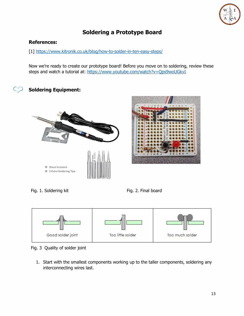
Soldering a Prototype Board
References:
[1] https://www.kitronik.co.uk/blog/how-to-solder-in-ten-easy-steps/
Now we’re ready to create our prototype board! Before you move on to soldering, review these
steps and watch a tutorial at: https://www.youtube.com/watch?v=Qps9woUGkvI
Soldering Equipment:
Fig. 1. Soldering kit Fig. 2. Final board
Fig. 3 Quality of solder joint
1. Start with the smallest components working up to the taller components, soldering any
interconnecting wires last.

14
2. Place the component into the board, making sure it goes in the right way around and
the part sits flush against the board.
3. Bend the leads slightly to secure the part.
4. Make sure the soldering iron has warmed up and if necessary use the damp sponge to
clean the tip.
5. Place the soldering iron on the pad.
6. Using your free hand feed the end of the solder onto the pad (see image below).
7. Remove the solder, then the soldering iron.
8. Leave the join to cool for a few seconds.
9. Using a pair of cutters trim the excess component lead (see image below).